

Page 1
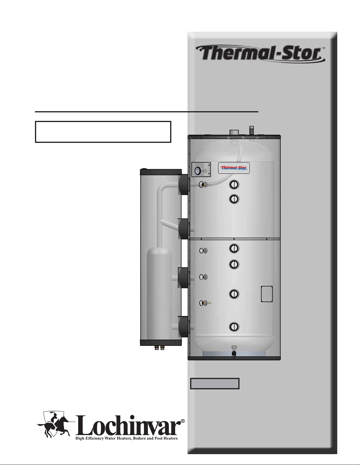
CAUTION:
This appliance is not intended for potable water.
TSU-I-O Rev A
Installation & Operation
Manual
Models: TSU 150 - 940
WARNING
Save this manual for future reference.
This manual must only be used by
a qualified heating installer / service
technician. Read all instructions
before installing. Perform steps in
the order given. Failure to comply
could result in severe personal
injury, death, or substantial property
damage.
Page 2
Contents
HAZARD DEFINITIONS .................................................... 2
PLEASE READ BEFORE PROCEEDING ........................ 3
1. GENERAL INFORMATION
Operating Restrictions ........................................................ 4
Tank Shipment................................................................... 4
Components .................................................................... 4-6
Spherical Heat Exchanger................................................. 7
2. PRE-INSTALLATION
Recommended Antifreeze Concentrations ........................ 8
Locating the Tank ............................................................... 8
Recommended Clearances ................................................ 8
3. SOLAR CONNECTIONS
Spherical Pressure Drop Calculations............................... 9
Piping Diagrams ............................................................... 10
4. HYDRONIC PIPING
Basic Hydronic Piping ...................................................... 11
Hydronic Heating Zoned with Circulators ......................... 11
Thermal-Stor Domestic Water Heating ............................ 11
Domestic Hot Water Priority ............................................. 11
High Output Piping ........................................................... 11
Relief Valves .................................................................... 12
Anti-Scald Mixing Valves .................................................. 13
Piping Diagrams........................................................... 14-16
5. STARTUP AND MAINTENANCE
System Startup ................................................................. 17
Maintenance Schedule ................................................ 17-18
Winterizing the System ............................................... 18
To Drain/Flush the System ......................................... 18
NOTES ............................................................................. 19
REVISION NOTES ............................................ Back Cover
Hazard definitions
The following defined terms are used throughout this manual to bring attention to the presence of hazards of various risk levels
or to important information concerning the life of the product.
DANGER
WARNING
CAUTION
CAUTION
NOTICE
DANGER indicates an imminently hazardous situation which, if not avoided, will result in death or serious
injury.
WARNING indicates a potentially hazardous situation which, if not avoided, could result in death or serious
injury.
CAUTION indicates a potentially hazardous situation which, if not avoided, may result in minor or
moderate injury.
CAUTION used without the safety alert symbol indicates a potentially hazardous situation which, if not
avoided, may result in property damage.
NOTICE indicates special instructions on installation, operation, or maintenance that are important but not
related to personal injury or property damage.
2
Page 3
Please read before proceeding
Installation & Operation Manual
WARNING
NOTICE
WARNING
Installer – Read all instructions before
installing. Perform steps in the order given.
Have this storage tank serviced/inspected
by a qualified service technician, at least
annually.
Failure to comply with the above could result
in severe personal injury, death or substantial
property damage.
When calling or writing about the appliance
– Please have the model and serial number
from the tank rating plate.
Consider piping and installation when
determining appliance location.
Any claims for damage or shortage in
shipment must be filed immediately
against the transportation company by the
consignee.
Factory warranty (shipped with appliance)
does not apply to appliances improperly
installed or improperly operated.
If the information in this manual is not
followed exactly, a fire or explosion may
result causing property damage, personal
injury or loss of life.
• Installation and service must be performed by a
qualified installer, service agency, or the gas supplier.
WARNING
Failure to adhere to the guidelines on this
page can result in severe personal injury,
death, or substantial property damage.
When servicing the Thermal-Stor –
• To avoid severe burns, allow the appliance to cool
before performing maintenance.
Appliance operation –
• Do not use this appliance if any part has been under
water. The possible damage to a flooded appliance can
be extensive and present numerous safety hazards. Any
appliance that has been under water must be replaced.
CAUTION
This appliance is not intended for potable
water.
This appliance MUST NOT be installed in
any location where gasoline or flammable
vapors are likely to be present.
WHAT TO DO IF YOU SMELL GAS
• Do not try to light any appliance.
• Do not touch any electric switch; do not
use any phone in your building.
• Immediately call your gas supplier from a
neighbor’s phone. Follow the gas supplier’s
instructions.
• If you cannot reach your gas supplier, call
the fire department.
3
Page 4
Installation & Operation Manual
1 General information
The Lochinvar Thermal-Stor stratified solar tank is designed to use a solar thermal collector system, in conjunction with a
back-up heat source, to provide water for a closed loop hydronic heating system. The appliance consists of a spherical heat
exchanger connected to an unlined storage tank. The Thermal-Stor tank uses solar heated water pumped through the spherical
heat exchanger to heat water in the tank. A backup heat source is used to maintain the desired tank temperature in the event that
adequate solar heat is not available. Tank components and specifications are detailed in FIG.’s 1-1 and 1-2, as well as in Tables
1A - 1D on pages 4 through 6.
The Thermal-Stor buffer tank can provide both thermal storage volume and hydraulic separation between the boiler or heat
pump and the building distribution system. The primary application of a buffer tank is to reduce boiler or heat pump cycling
in systems operating below design load conditions, or in systems having several low Btu heat loads calling for heat at different
times. The solar-assisted buffer tank provides thermal storage volume which can help reduce short-cycling, leading to longer
runtimes, higher efficiency and longer equipment life for the solar thermal system and heat source. If piped correctly, the buffer
tank can also function as a hydraulic separator, effectively separating the flow in the boiler loop from the flow in the distribution
system (FIG.’s 4-2 and 4-3, on pages 14 and 15). This tank has many applications including geothermal, pool and space heating.
Consult the factory if your specific application is not covered in this manual. This tank is not intended for use in gravity water
heating applications.
Operating Restrictions:
• Maximum stored water temperature is 210°F.
• Maximum working pressure for the vessel is 125 psig.
Tank shipment
Tanks taller than 7.5 feet will be shipped horizontally. Four
shipping legs are used to secure the tank to a pallet, and holes
are provided in the top cover for access to lifting lugs. The
shipping legs should be removed when the tank is removed
from the shipping crate.
Use field-supplied insulation to pack the shipping and lug
compartments, then use the factory provided covers to
conceal compartments upon final installation.
Table 1A
Thermal-Stor
Tank Component Materials
Component Material
Tank Steel SA414-G
Insulation Polyurethane Foam
Jacket Pre-paint Sheet Metal
Table 1B
Spherical Heat Exchanger
Component Materials
Component Material
Housing Steel S 235 JR
Heat Exchanger Coil Copper
Insulation Polyurethane Foam
Jacket Polypropylene
4
Page 5
1 General information (continued)
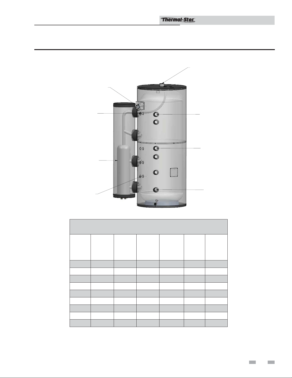
Figure 1-1 Thermal-Stor solar stratified tank components
TEMPERATURE
GAUGE
Installation & Operation Manual
AUXILIARY
HEAT OUTLET
BACKUP
HEAT SOURCE
SENSOR
SPHERICAL
HEAT EXCHANGER
SOLAR
SENSOR
IMG00104
BACKUP
HEAT SOURCE
INLET
BACKUP
HEAT SOURCE
RETURN
AUXILIARY
HEAT INLET
Table 1C
Thermal-Stor Tank Specifications
Boiler
Supply/
Return
(NPT)
Model
Tank
Diameter
(in.)
Jacket
Diameter
(in.)
Hydronic
Tappings
(NPT)
TSU150 24 28 2" 2" 140 1775
TSU200 28 32 2" 2" 190 2300
TSU257 30 34 2" 2" 240 2875
TSU350 36 40 2" 2" 340 3775
TSU423 36 40 2" 2" 420 4650
TSU504 42 46 2" 2" 495 5475
TSU650 48 52 2" 2" 645 7050
TSU752 48 52 2" 2" 745 8100
TSU940 48 52 2" 2" 920 10000
Tank
Water
Volume
(gal.)
Full
Weight
(lbs)
5
Page 6
1 General information
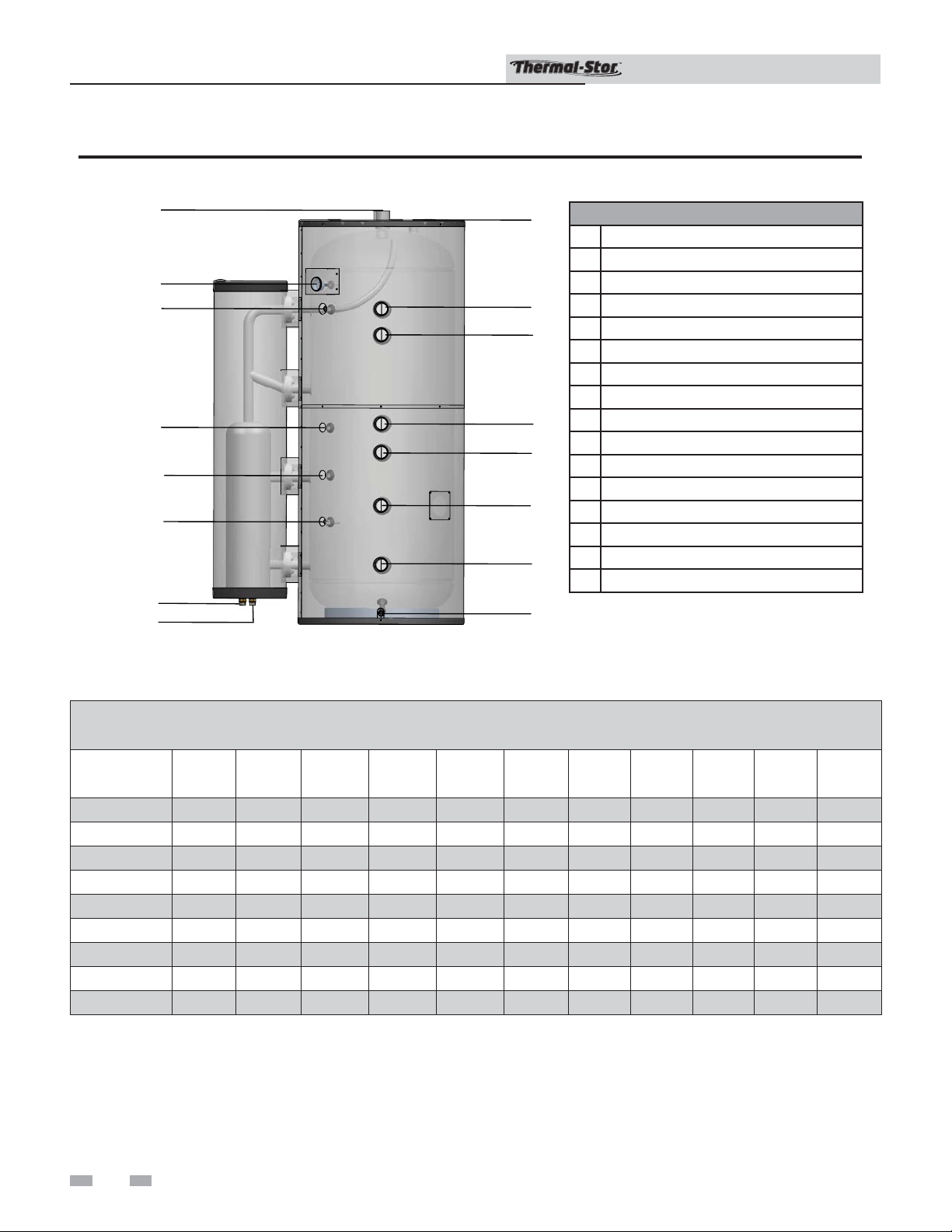
Figure 1-2 Thermal-Stor tappings
I
I
J
J
K
K
L
L
M
M
N
N
P
O
O
IMG00096
Installation & Operation Manual
H
G
F
E
D
C
B
A
Thermal-Stor Elements
A
Drain Valve
B
Auxiliary Heat Return
C
Low Temp Water Return
D
High Temp Water Return
E
Backup Heat Source Return
F
Space Heat Supply
G
Backup Heat Source Supply
H
Relief Valve / Air Vent
I
Auxiliary Heat Outlet
J
Heat Source Thermometer
K
Backup Heat Source Sensor
L
Sensor (Optional)
M
Sensor (Optional)
N
Solar Sensor
O
Spherical Exchanger, Inlet (Red Label)
P
Spherical Exchanger, Outlet (Blue Label)
Model
TSU150
TSU200
TSU257
TSU350
TSU423
TSU504
TSU650
TSU752
TSU940
Table 1D
Tapping Measurements (From Floor)
A
(in.)
2 1/4 10 3/4 21 1/4 28 3/4 33 50 1/4 55 1/4 71 75 3/4 3 1/2 3 1/2
2 1/4 11 1/4 22 3/4 33 38 1/2 55 1/2 60 1/2 76 80 4 1/4 4 1/4
2 1/4 15 1/2 34 1/2 42 1/2 49 62 3/4 67 3/4 87 91 3/4 8 1/2 8 1/2
3 1/4 17 36 3/4 46 1/2 52 3/4 61 1/4 66 1/4 87 1/4 91 1/4 10 10
3 1/4 17 40 1/4 52 58 1/4 75 3/4 80 3/4 100 104 10 10
2 1/2 18 1/2 33 1/2 42 1/4 49 59 3/4 64 3/4 87 91 1/2 11 1/2 11 1/2
2 1/4 20 1/2 36 3/4 44 1/2 51 60 3/4 65 3/4 88 93 13 1/2 13 1/2
2 20 1/2 38 1/4 50 57 1/2 70 75 100 104 3/4 10 1/2 10 1/2
2 1/4 20 1/2 49 63 70 1/2 88 1/2 93 1/2 124 129 13 1/2 13 1/2
B
(in.)
C
(in.)
D
(in.)
E
(in.)
F
(in.)
G
(in.)
H
(in.)
I
(in.)
O
(in.)
P
(in.)
6
Page 7

1 General information (continued)
Installation & Operation Manual
Spherical heat exchanger
The Thermal-Stor uses a copper finned tube spherical heat
exchanger to provide optimum solar stratified charging. The
spherical exchanger helps maintain optimal use of solar energy
for hydronic heating. The multi-functional design improves
efficiency in every system. Insulated with polyurethane foam,
the spherical heat exchanger and tank maintain a space-saving
design with minimal heat loss. Refer to FIG. 1-3 and Tables 1E
and 1F for additional spherical heat exchanger information
and measurements.
Figure 1-3 Spherical heat exchanger w/ tank
B
Table 1E
Tank with Spherical Measurements
Model
TSU150 SHX40000 44 1/2 28
TSU200 SHX40000 48 1/4 32
TSU257 SHX40001 50 1/4 34
TSU350 SHX40001 56 1/4 40
TSU423 SHX40002 56 1/4 40
TSU504 SHX40002 62 1/4 46
TSU650 SHX40003 71 1/4 52
TSU752 SHX40003 71 1/4 52
TSU940 SHX40004 71 1/4 52
Spherical
Model
A
(in.)
(in.)
B
A
IMG00107
Table 1F
Spherical Heat Exchanger Specifications
Tank
Model
SHX40000 8 1/2 14 61 0.75" 28 0.55 7.9 8.45
SHX40001 8 1/2 14 61 0.75" 42 0.65 7.8 8.45
SHX40002 8 1/2 14 61 1" 59 1.1 7.35 8.45
SHX40003 11 3/4 17 61 1.25" 102 2.0 15.8 17.8
SHX40004 11 3/4 17 80 1.25" 102 2.0 15.8 17.8
Diameter
(in)
Jacket
Diameter
(in)
Jacket
Height
(in)
Solar
Inlet
Return
(NPT)
HEX
Surface
Area
(ft2)
HEX
Water
Volume
(gal)
Tank
Water
Volume
(gal)
Total
Water
Volume
(gal)
7
Page 8

2 Pre-installation
Installation & Operation Manual
1. The installation must conform to the instructions in this
manual and all applicable local, state, provincial, and
national codes, laws, regulations, and ordinances.
Installations in Canada must conform to B149.2 Installation
Code.
2. If the heat source water contains antifreeze, a maximum
50/50 mixture of inhibited propylene glycol is recommended.
The heat source water, including additives, must be
non-toxic, having a toxicity rating or class of 1, as listed in
the Clinical Toxicology of Commercial Products.
WARNING
3. Read and understand all installation requirements in
this manual.
Do not use automotive, ethylene glycol or
petroleum-based antifreeze. Do not use
any undiluted antifreeze. This can cause
severe personal injury, death, or substantial
property damage.
Table 2A
Recommended Antifreeze Concentrations
Glycol Freeze
Protection
Propylene Glycol
Only
Percentage
20 18°F
30 8°F
40 -6°F
50 -28°F
Freeze
Protection
Locating the Tank
1. Choose a location for the Thermal-Stor centralized to
the piping system. You must also locate the Thermal-Stor
where it will not be exposed to freezing temperatures.
Additionally, you will need to place the tank so that
the controls, drain, and inlet/outlets are easily accessible.
This tank must not be installed outdoors, as it is
certified as an indoor appliance, and must be kept vertical
on a level surface.
2. Table 1C on page 5 shows the weight of all the tanks filled
with water. Ensure that the location chosen for the tank
is capable of supporting the weight.
CAUTION
3. The tank may be located some distance from the heat
source provided that the pump is designed to provide
enough flow for both units to perform properly. The
further the distance from the tank to the heat source, the
longer the response time will be to provide sufficient heat
to the tank. Insulate piping between the heat source and
the tank.
WARNING
This tank must be placed where leakage
from the relief valve, leakage from the
related piping, or leakage from the tank
or connections, will not result in damage
to the surrounding areas, or to the lower
floors of the building. A tank should always
be located in an area with a floor drain or
installed in a drain pan suitable for tanks.
Lochinvar shall not be held liable for any
such water damage.
Failure to properly support the tank could
result in property damage or personal
injury.
Recommended Clearances
The installation location must provide adequate clearances
for servicing and proper operation of the appliance.
A 12-inch vertical clearance is recommended from the top of
the appliance. A zero clearance is allowed for the sides of the
appliance. However, boiler and servicing clearances must be
figured when locating the appliance.
8
Page 9

TSU150-200 /
SHX40000
TSU257-350 /
SHX40001
TSU423-504 /
SHX40002
TSU650-940 /
SHX40003
SHX40004
0
5
10
15
20
25
30
0 gpm 2 gpm 4 gpm 6 gpm 8 gpm 10 gpm 12 gpm 14 gpm
Installation & Operation Manual
3 Solar connections
A solar thermal system consists of several components selected to work together to convert solar energy into hot water for
various applications. A controller is used to turn on a pump when the fluid in the solar collectors is warmer than the water in the
Thermal-Stor tank plus the differential. The pump will transport hot fluid from the collector to the heat exchanger and replace it
with cooler fluid returning. The collectors, pump station and heat exchanger should be connected with supply and return piping
that is insulated to minimize heat losses (FIG. 3-1, page 10). The system should be equipped with over-temperature and overpressure devices that prevent unsafe operating conditions. When multiple Thermal-Stor tanks are used, they should be connected
in reverse-return arrangement (FIG. 3-2, page 10). This will help ensure that solar heated water is distributed evenly between the
heat exchangers. Pressure drop and maximum operating values for the Thermal-Stor spherical heat exchanger are listed in Tables
3A - 3C.
Installation and commissioning must be carried out by a licensed contractor. Take appropriate safety measures when carrying
out any installation work on the roof and observe all relevant accident prevention regulations. It is the installer’s responsibility to
comply with the building and installation codes in effect and all regulations that apply to the operation of a solar hot water system.
MODEL
TSU150
TSU200
TSU257
TSU350
TSU423
TSU504
TSU650
TSU752
TSU940
30
Table 3A
Spherical Heat Exchanger
Pressure Drop Values
PRESSURE DROP PSI)
SPHERICAL
MODEL
1
GPM2 GPM4GPM6GPM8GPM10GPM12GPM14GPM
SHX40000 0.20 0.68 2.29 4.66 7.71 11.39 15.67 20.52
SHX40001 0.24 0.81 2.71 5.52 9.13 13.49 18.56 24.31
SHX40002 0.07 0.23 0.78 1.59 2.64 3.90 5.36 7.02
SHX40003 0.03 0.09 0.30 0.61 1.01 1.50 2.06 2.70
SHX40004 0.03 0.09 0.30 0.61 1.01 1.50 2.06 2.70
Table 3C
Spherical Heat Exchanger Pressure Drop Chart
Table 3B
Spherical Maximum Operating
Conditions
Copper Heat
Exchanger
Temperature 230°F 230°F
Pressure 145 psi 125 psi
Tank
25
20
15
10
PRESSURE DROP, PSI
5
0
02468101214
FLOW RATE, GPM
TSU257-350/
SHX40001
TSU150-200/
SHX40000
TSU423-504/
SHX40002
TSU650-940/
SHX40003
SHX40004
9
Page 10

3 Solar connections
Figure 3-1 Solar System Piping
SOLAR
COLLECTOR
SOLAR AIR
RELEASE VENT
(OPTIONAL)
SPHERICAL
HEAT EXCHANGER
TEMPERATURE
GAUGE
Installation & Operation Manual
PRESSURE
RELIEF VALVE
TEMPERATURE GAUGE
(TYPICAL)
SOLAR PUMP STATION /
CONTROLLER
FLUSH VALVE
Figure 3-2 Solar System Piping with Multiple Heat Exchangers
SOLAR AIR
RELEASE VENT
SOLAR
COLLECTOR
(OPTIONAL)
TEMPERATURE
GAUGE
FILL AND
EXPANSION
TANK
SOLAR
SENSOR
SPHERICAL
HEAT EXCHANGER
IMG00095
10
TEMPERATURE
GAUGE
(TYPICAL)
SOLAR
PUMP STATION /
CONTROLLER
NOTICE
SOLAR
PRESSURE
T
P
T
RELIEF VALVE
EXPANSION
TANK
SENSOR
IMG00108
Please note that these illustrations are meant to show system piping concept only, the installer is
responsible for all equipment and detailing required by local codes.
Page 11

4 Hydronic piping
Installation & Operation Manual
Basic hydronic piping
Depending upon the application, there are many different
piping arrangements that can be applied to the Thermal-Stor
buffer tank. A pressure relief valve must be installed on each
boiler and each buffer tank as regulations require. Installation
and commissioning must always be carried out by a licensed
and experienced contractor. It is the responsibility of the
installer to comply with all building and installation codes in
effect.
Hydronic heating zoned with circulators
FIG. 4-2 on page 14 shows typical space heating piping for a
Thermal-Stor tank. The functions of some of the illustrated
components are as follows:
• Shut-off valves (recommended) - Used to isolate the
tank for servicing.
• Backflow Preventer (required by some codes) - Used to
prevent water from backing out into the piping in the
event that inlet water pressure drops.
• Expansion Tank (required for thermal expansion) - Tank
absorbs the increased volume caused by heating water.
Refer to the expansion tank manufacturer’s instructions for
proper sizing and use.
NOTICE
If a valve is used between an expansion tank
and the tank inlet, the installer must ensure
that the valve is open.
• Circulation Pump (recommended) - Used to circulate and
maintain hot water within the piping system.
• Check Valve (required by some codes) - Used to allow
water to flow in only one direction, preventing back-flow.
• Drain (required) - Used to drain the tank for inspection
or servicing.
• Mixing valve (required for domestic water) - Used to mix
hot water with cold water to ensure constant, safe outlet
temperatures.
• Unions (optional) - Used to disconnect the tank in the
unlikely event that this is necessary for service.
Thermal-Stor domestic water heating
When paired with an indirect water heater or a heat exchanger
(FIG. 4-3, page 15) the Thermal-Stor buffer tank can be used
to heat domestic water. The hottest water is taken from the
auxiliary heat supply and piped to the indirect heater where it
is used to heat domestic potable water. The water is returned
to the high temperature return tapping so the hottest water
will be available for domestic heating while preserving tank
stratification. Other hydronic heating applications will be piped
into the low temperature or auxiliary returns.
Domestic hot water priority
Domestic Hot Water (DHW) priority allows a boiler to be
used for both space and domestic water heating by turning
off the boiler output for space heating when there is a call for
domestic hot water. Outdoor reset is required with the use of
DHW priority in order to regulate water temperature and satisfy
heating load. During calls for DHW, the outdoor reset control
will turn off the circulation pump and raise the boiler water
temperature to a minimum of 180°F (FIG. 4-5, page 17).
High output piping
When a large amount of hot water is required for hydronic
heating, there are several different piping alternatives. When
hydraulic separation is desired, multiple boilers coupled with
a buffer tank can provide adequate water for both space and
domestic water heating (FIG. 4-4, page 16).
Multiple Thermal-Stor tanks can also be piped together if there
is a continuous demand for heating water. This is typically
done in the reverse-return arrangement. This method uses
more piping than direct-return systems, but the temperature
and boiler flow are more balanced throughout each tank.
To ensure even charging and discharging of each tank, it is
recommended that only tanks of the same size are placed in the
same manifold. It is recommended that each tank be equipped
with its own isolation valves, unions and drains, so that one
tank may be removed from the system if necessary. It is only
necessary to use one backup heat source sensor for control
(FIG. 4-6, page 17).
NOTICE
Be sure to field-install plugs or caps on any
tank tappings that are not in use.
CAUTION
Piping must be balanced. Failure to balance
piping could result in uneven flow and
improper operation.
11
Page 12

4 Hydronic piping
Installation & Operation Manual
Relief Valves
WARNING
For protection against excessive pressure,
install temperature and pressure protective
equipment required by local codes. A relief
valve must be certified by a nationally
recognized testing laboratory that maintains
periodic inspection of listed equipment or
materials. The equipment and materials
must meet the requirements for Relief Valves
and Automatic Gas Shutoff Devices for Hot
Water Supply Systems, ANSI Z21.22, as well
as the standard CAN1-4.4, Temperature,
Pressure, Temperature and Pressure Relief
Valves and Vacuum Relief Valves. The relief
valve shall be marked with a maximum
set pressure, not to exceed the maximum
working pressure of the appliance. It shall
also have an hourly rated discharge capacity
not less than the Btu output of the heat
source.
Pressure only relief valves (POV)
A pressure relief valve should be installed in the connection
provided on the top of the tank containing hydronic water. It
is imperative that the relief valve be correctly installed because
it also serves as an air vent. Do Not place any valve between
the relief valve and the opening provided. To prevent water
damage, the discharge from the relief valve should be piped to
a suitable floor drain for disposal when relief occurs Do Not
install reducing coupling or other restrictions in the discharge
line. The discharge line should allow complete drainage of the
valve and line. The POV should be sized in accordance with the
maximum working pressure of the tanks, and the Btu output of
the backup heat source.
It is recommended to have a relief valve sized in accordance
with ASME Boiler and Pressure Vessel Code, Section IV
“Heating Boilers”. ASME states in Section VIII, Division 1,
paragraph UG-125 (a), “All pressure vessels within the scope of
this division, irrespective of size or pressure, shall be provided
with pressure relief devices in accordance with the requirements
of UG-125 through UG-137.”
NOTICE
Verify that the relief valve complies with
local codes. If the relief valve does not
comply with local codes, replace it with
one that does. Follow the installation
instructions in this section.
Do not place a valve between the relief valve
and the tank.
12
Figure 4-1 Relief valve
IMG00111
Standard Installation
Relief Valve Discharge Piping
Relief valve discharge piping MUST be:
- Made of material serviceable for a temperature of
250°F or greater
- Directed so that hot water flows away from all
persons
- Directed to a suitable place for disposal
- Installed so as to allow complete draining of the relief
valve and discharge line
- Terminated within 6" of the floor
Relief valve discharge piping MUST NOT be:
- Excessively long. Using more than two (2) elbows or
15 feet of piping can reduce discharge capacity
- Directly connected to a drain (Refer to local codes)
- Subject to freezing
WARNING
CAUTION
WARNING
Do not install any valve between the relief
valve and its connection or on the relief
valve discharge piping. Improper placement
and piping of relief valve can cause severe
personal injury, death or substantial
property damage.
The relief valve is not intended for constant
duty, such as relief of pressure due to
repeated normal system expansion. Correct
this condition by installing a properly sized
expansion tank in a domestic water system.
Refer to the expansion tank manufacturer’s
installation instructions for proper sizing.
Failure to install and maintain a new, listed
and properly sized relief valve will relieve
the manufacturer from any claim which
might result from excessive temperature and
pressure.
Page 13

4 Hydronic piping (continued)
Anti-scald mixing valves
Anti-scald valves used with water heaters are also called
tempering valves or mixing valves. An anti-scald valve mixes
cold water with the outgoing hot water to assure that hot
water reaching a building fixture is at the correct temperature.
A mixing valve is required when the Thermal-Stor is used to
generate domestic hot water.
Installation & Operation Manual
NOTICE
The temperature of water going to the fixtures may be more
carefully controlled through the use of a thermostatic mixing
valve. This device blends a controlled amount of cold water
with the hot water leaving the tank so that water at a more
constant temperature exits the mixing valve. Always consult
the mixing valve manufacturer’s instructions and guidelines for
correct piping and usage.
WARNING
WARNING
ASSE1017 and ASSE1070 certified mixing
valves are required.
Hot water can scald! To avoid scalding
potential, mixing valves must be selected and
installed according to valve manufacturer’s
instructions and recommendations. Mixing
valves should be installed by a licensed
contractor.
An anti-scald mixing valve does not
eliminate the risk of scalding.
• Feel water before bathing or showering.
• If anti-scald or anti-chill protection is
required, use devices specifically
designed for such service. Install
these devices in accordance with their
manufacturer’s instructions.
13
Page 14

4 Hydronic piping
Figure 4-2 Piping with Hydronic Heating
Installation & Operation Manual
MAKE UP
W
ATER
PRESSURE
REDUCING
VALVE
PRESSURE
GAUGE
SPACE
HEAT
SUPPLY
TEMPERATURE
HIGH
TEMPERATURE
RETURN
GAUGE
AIR
SEPARATOR
BACKFLOW
PREVENTER
ZONE
CIRCULATORS
(TYPICAL)
EXPANSION
TANK
PRESSURE
RELIEF
VALVE
LOW TEMP.
ZONE
HIGH TEMP.
ZONE #1
Y-STRAINER
(TYPICAL)
BOILER
CIRCULATOR
HIGH TEMP.
ZONE #2
PRESSURE
RELIEF
VALVE
NOTICE
LOW
TEMPERATURE
RETURN
T&P
GAUGE
DRAIN
IMG00123
Please note that these illustrations are meant to show system piping concept only, the installer is responsible for
all equipment and detailing required by local codes.
14
Page 15

4 Hydronic piping (continued)
Figure 4-3 Domestic Indirect Water Heating
Installation & Operation Manual
PRESSURE
GAUGE
MAKE UP
WATER
PRESSURE
REDUCING
VALVE
SUPPLY
TEMPERATURE
HIGH
TEMPERATURE
RETURN
LOW
TEMPERATURE
RETURN
SPACE
HEAT
SEPARATOR
AUXILIARY
GAUGE
AIR
HEAT
SUPPLY
BACKFLOW
PREVENTER
PRESSURE
ZONE
C
IRCULATORS
(TYPICAL)
EXPANSION
TANK
RELIEF
VALVE
LOW TEMP.
ZONE
HIGH TEMP.
ZONE #1
Y-STRAI NER
(TYPICAL)
BOILER
CIRCULATOR
CHECK
VALVE
T&P
GAUGE
HIGH TEMP.
ZONE #2
PRESSURE
RELIEF
VALVE
DRAIN
IMG00125
MIXING
VALVE
SHUTOFF
VALVE
(TYPICAL)
UNION
SHOCK
ARRESTOR
DOMESTIC
HOT WATER
CHECK
VALVE
DOMESTIC
COLD WATER
BRAISED PLATE
HEAT EXCHANGER
WARNING
NOTICE
Boiler must be sized to meet all space heating and domestic hot water loads simultaneously. Failure to properly
size the heat source can cause operational issues.
Please note that these illustrations are meant to show system piping concept only, the installer is responsible for
all equipment and detailing required by local codes.
15
Page 16

4 Hydronic piping
Figure 4-4 Multiple Boiler Piping - Single Temperature
Installation & Operation Manual
PRESSURE
GAUGE
MAKE UP
WATER
PRESSURE
REDUCING
VALVE
AIR
SEPARATOR
EXPANSION
TANK
SPACE HEAT
SUPPLY
AUXILIARY
HEAT SUPPLY
TEMPERATURE
GAUGE
BACKFLOW
PREVENTER
ZONE #1
ZONE
CIRCULATORS
(TYPICAL)
PRESSURE
RELIEF
VALVE
T&P
GAUGE
ZONE #2
DRAIN
ZONE #3
PRESSURE
RELIEF
VALVE
Y STRAINER
(TYPICAL)
BOILER
CIRCULATOR
I
MG00121
UNION
SHOCK
ARRESTOR
DOMESTIC
HOT WATER
MIXING
VALVE
BRAISED PLATE
HEAT EXCHANGER
CHECK
VALVE
DOMESTIC
COLD WATER
WARNING
NOTICE
16
Boiler must be sized to meet all space heating and domestic hot water loads simultaneously. Failure to properly
size the heat source can cause operational issues.
Please note that these illustrations are meant to show system piping concept only, the installer is responsible for
all equipment and detailing required by local codes.
Page 17

4 Hydronic piping (continued)
Figure 4-5 DHW Priority Piping - Multiple Temperature Space Heating
HIGH TEMP.
HIGH TEMP.
ZONE #1
MAKE UP
WATER
FILL
VALVE
ZONE #2
CHECK
VALVE
PRESSURE
GAUGE
PRESSURE
REDUCING
VALVE
AIR
SEPARATOR
SPACE
SUPPLY
TEMPERATURE
HIGH
TEMPERATURE
RETURN
BACKFLOW
PREVENTER
HEAT
GAUGE
ZONE
CIRCULATORS
(TYPICAL)
EXPANSION
PRESSURE
PRESSURE
RELIEF
RELIEF
VALVE
VALVE
TANK
LOW TEMP.
ZONE
RECIRCULATION
PRESSURE
RELIEF
VALVE
Installation & Operation Manual
RECIRCULATION
LINE
PUMP
SHOCK
ARRESTOR
MIXING
VALVE
CHECK
VALVE
SHUTOFF
VALVE
(TYPICAL)
DOMESTIC
HOT WATER
LOW
TEMPERATURE
RETURN
Figure 4-6 Multiple Tank Piping
PRESSURE
REDUCING
VALVE
PRESSURE
GAUGE
MAKE UP
WATER
SPACE HEAT
SUPPLY
SHUTOFF
VALVE
(TYPICAL)
UNION
TEMPERATURE
GAUGE
AIR
SEPARATOR
Y-STRAINER
(TYPICAL)
BACKFLOW
PREVENTER
PRESSURE
RELIEF
VALVE
ZONE #1
ZONE
CIRCULATORS
(TYPICAL)
T&P
GAUGE
DRAIN
ZONE #2
ZONE #3
CHECK
VALVE
Y-STRAINER
(TYPICAL)
BOILER
CIRCULATOR
IMG00124
PRESSURE
RELIEF
VALVE
DOMESTIC
COLD WATER
WARNING
NOTICE
T&P
GAUGE
DRAIN
Boiler must be sized to meet all space heating and domestic hot water loads simultaneously.
Failure to properly size the heat source can cause operational issues.
Please note that these illustrations are meant to show system piping concept only, the installer
is responsible for all equipment and detailing required by local codes.
IMG00102
17
Page 18

5 Startup and maintenance
Installation & Operation Manual
System startup
1. Make sure the system is free of leaks and that air is
purged from the system.
CAUTION
2. Many soldering fluxes contain Zinc Chloride which
can cause severe corrosion damage to stainless steel. After
completing all domestic water connections, flush the
Thermal-Stor tank thoroughly before leaving the installation.
This is particularly important if the Thermal-Stor will be
unused for an extended period of time after installation.
Flush the storage tank by drawing at least three times its
volume from the tank.
3. Make sure that each zone valve or circulator operates
when, and only when, its thermostat calls for heat. Let each
zone operate long enough to purge any remaining air from
the system.
Refer to the heat source and solar Installation and Operation
Manuals for additional start-up information.
Fix any leaks found before proceeding
further. Leakage from the heat source and
solar piping can result in severe damage to
the system.
Maintenance Schedule
The Lochinvar Thermal-Stor solar tank is an extremely simple
device and as such requires very little maintenance. There are,
however, several items which should be inspected on an annual
or as needed basis to ensure a reliable supply of hot water:
• Ensure that the boiler and solar water piping are free of
leaks.
• If there is an oil lubricated circulator in the system, make
sure it is lubricated as called for by the circulator
manufacturer.
• Make sure that the heat source is maintained in accordance
with the manufacturer’s instructions.
• If antifreeze is required to keep the water chemistry
within the parameters shown in Table 2A (see Section
2 - Pre-Installation), make sure that this system is properly
maintained.
Annual service by a qualified service technician
should include the following:
Any procedure required by local codes.
Verify system pressure. Air venting procedure may require
adding water to bring boiler system up to pressure, typically
12 psig minimum.
Manually operate relief valve at least once a year. This will
release some hot water.
WARNING
Move operating lever to open position for a few seconds
and then move it back, allowing it to snap closed. After the
relief valve is operated, if it continues to release water, close
the cold water inlet to the water heater immediately. Follow
the draining instructions, and replace the relief valve. If
the relief valve weeps periodically, it may be due to thermal
expansion. Do not plug the relief valve or discharge piping.
In this case, ensure that the expansion tank is properly sized
and charged to the appropriate pressure.
DANGER
Verify that expansion tank pressure is equal to system
pressure.
Before operating a relief valve, make sure no
one is in front of or around the relief valve
discharge piping. Hot discharge water can
cause severe personal injury or substantial
property damage.
Plugging the relief valve or discharge piping
can cause excessive pressure in the water
heater, resulting in severe personal injury,
death, or substantial property damage.
18
Page 19

5 Startup and maintenance
Installation & Operation Manual
Follow instructions on circulator to oil, if required.
Check mixing valve, valves, pipes, and fittings for leaks.
Check function of the field-installed controls and valves.
See component manufacturer’s instructions.
Review owner’s maintenance responsibilities and their
frequencies, including any not listed in the following
section.
Owner monthly maintenance to include:
Visually check valves, pipes, and fittings for leaks. Call a
qualified service technician to repair leaks.
Winterizing the system
Drain the tank and spherical heat exchanger if the appliance will
be off and exposed to freezing temperatures. Freezing water will
expand and damage the appliance.
• If the tank, spherical heat exchanger and heat source
water contain sufficient antifreeze, then the tank does
not need to be drained.
If antifreeze is used in the heat source water, check the
concentration. Heat source water (including additives) must be
non-toxic, having a toxicity rating or class of 1, as listed in the
“Clinical Toxicology of Commercial Products”. A maximum
50/50 mixture of inhibited propylene glycol is recommended.
Follow the antifreeze manufacturer’s instructions.
WARNING
Do not use automotive, ethylene glycol or
petroleum-based antifreeze. Do not use
any undiluted antifreeze. This can cause
severe personal injury, death, or substantial
property damage.
To drain/flush the system
1. Turn OFF main electrical power to the tank, solar collectors
and any other heat source connected to the tank.
2. Turn OFF the main manual gas shutoff for any heat source
connected to the tank.
3. Turn OFF electrical power to the circulating pump (if used).
4. Close off the boiler or heat source inlet connection.
5. Ensure that the drain (located on the bottom of the tank)
is routed to a floor drain with adequate capacity to allow
the tank to be flushed.
6. Open the drain valve and allow the incoming cold water
“Boiler Return” to flush the soft sediment out of the bottom
of the storage tank.
CAUTION
7. Observe the color of the water initially discharged from
the tank drain. This water will generally be milky or
slightly discolored by the sediment discharge. Allow the
drain to run until the water runs clear.
8. Close the drain valve on the tank.
9. Open the hot water relief/air valve on the top of the
tank.
10. Turn ON main electrical power for the heat source, solar
collectors, tank and circulating pump.
11. Turn ON gas supply to the heat source(s).
12. Observe heat source and solar piping to ensure that all
components are functioning properly.
Hot water will be released under pressure.
Avoid contact with hot discharge water to
prevent the risk of severe scald injury.
19
Page 20

Revision Notes: Revision A (ECO C08886)
initial release.
11/11 - Printed in U.S.A.
TSU-I-O Rev A
 Loading...