

Lochinvar Power-Fin Series Installation And Service Manual
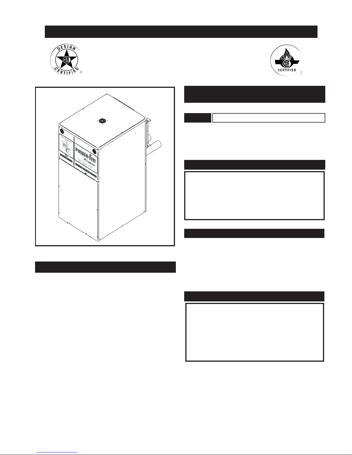
FIG. 1 Front View
Installation and service must be performed by a qualified
service installer, service agency or the gas supplier.
Factory warranty (shipped with unit) does not apply to units
improperly installed or improperly operated.
Experience has shown that improper installation or system
design, rather than faulty equipment, is the cause of most
operating problems.
1. Excessive water hardness causing a lime/scale build-up in
the copper tube is not the fault of the equipment and is not
covered under the manufacturer's warranty (see Water
Treatment and Water Chemistry).
2. Excessive pitting and erosion on the inside of the copper
tube may be caused by too much water velocity through the
tubes and is not covered by the manufacturer's warranty
(see Boiler Flow Rates and Temperature Rise for flow
requirements).
This manual supplies information for the installation, operation
and servicing of the appliance. It is strongly recommended that
this manual be reviewed completely before proceeding with an
installation.
Upon receiving equipment, check for signs of shipping
damage. Pay particular attention to parts accompanying the
boiler, which may show signs of being hit or otherwise being
mishandled. Verify total number of pieces shown on packing
slip with those actually received. In case there is damage or a
shortage, immediately notify carrier.
DO NOT USE THIS APPLIANCE IF ANY PART
HAS BEEN UNDER WATER. THE POSSIBLE
DAMAGE TO A FLOODED APPLIANCE CAN
BE EXTENSIVE AND PRESENT NUMEROUS
SAFETY HAZARDS. ANY APPLIANCE THAT
HAS BEEN UNDER WATER MUST BE
REPLACED.
DO NOT:
CHECKING EQUIPMENT
IMPROPER INSTALLATION, ADJUSTMENT,
ALTERATION, SERVICE OR MAINTENANCE can
cause injury or property damage. Refer to this manual.
For assistance or additional information, consult a
qualified installer, service agency or the gas supplier.
WARNING
Retain this manual for future reference.
NOTE:
SPECIAL INSTRUCTIONS
TO OWNER
WARRANTY
INSTALLATION AND SERVICE MANUAL
Power-Fin
®
HOT WATER HEATING BOILERS
DOMESTIC WATER HEATERS
500,000, 750,000, 1,000,000 and 1,300,000 Btu/hr MODELS
PB-PF-i&s-03
Warranty . . . . . . . . . . . . . . . . . . . . . . . . . . . . . . . . . . . . . . . .1
Safety Warnings . . . . . . . . . . . . . . . . . . . . . . . . . . . . . . . . . .2
Codes . . . . . . . . . . . . . . . . . . . . . . . . . . . . . . . . . . . . . . . . .3
Installation Requir
ements
Location . . . . . . . . . . . . . . . . . . . . . . . . . . . . . . . . . . . . . . . . .3
Clearances . . . . . . . . . . . . . . . . . . . . . . . . . . . . . . . . . . . . . . .4
Combustion/Ventilation Air Requirements . . . . . . . . . . . . . .4
Combustion Air Supplied to the Equipment Room . . . . . . .6
V
enting . . . . . . . . . . . . . . . . . . . . . . . . . . . . . . . . . . . . . . . . .6
General Venting Information . . . . . . . . . . . . . . . . .7
Common Venting Systems . . . . . . . . . . . . . . . . . . .9
Conventional Vertical Category I Negative Draft . . . . . . . .10
A Vertical Category II Negative Draft Venting System . . .10
Sidewall Venting . . . . . . . . . . . . . . . . . . . . . . . . . . . . . . . . .11
Direct Vent and DirectAire Vent Systems . . . . . . . . . . . . . .13
DirectAire Vent Systems . . . . . . . . . . . . . . . . . . . . . . . . . . .14
Vertical DirectAire w/Sidewall Combustion Air . . . . . . . .15
Vertical DirectAire Venting w/
Rooftop Combustion Air . . . . .16
Horizontal DirectAire w/Vertical Combustion Air . . . . . . .17
Horizontal DirectAire w/Sidewall Combustion Air . . . . . .17
Vertical Direct Vent Systems . . . . . . . . . . . . . . . . . . . . . . . .18
Horizontal Direct Vent . . . . . . . . . . . . . . . . . . . . . . . . . . . .18
Gas Supply
. . . . . . . . . . . . . . . . . . . . . . . . . . . . . . . . . . . . .20
Gas Pressure Test . . . . . . . . . . . . . . . . . . . . . . . . . . . . . . . .20
Gas Connection . . . . . . . . . . . . . . . . . . . . . . . . . . . . . . . . . .20
Gas Train and Controls . . . . . . . . . . . . . . . . . . . . . . . . . . . .21
Gas Piping . . . . . . . . . . . . . . . . . . . . . . . . . . . . . . . . . . . . . .21
Gas Manifold Pressure Adjustment . . . . . . . . . . . . . . . . . .22
Checking Gas Supply Pressure . . . . . . . . . . . . . . . . . . . . . .22
Checking Manifold Gas Pressure . . . . . . . . . . . . . . . . . . . .23
Water Connections . . . . . . . . . . . . . . . . . . . . . . . . . . . . . . .24
Heat Exchanger . . . . . . . . . . . . . . . . . . . . . . . . . . . . . . . . . .24
Minimum Water Temperatures . . . . . . . . . . . . . . . . . . . . . .24
Low Water Cutoff Devices . . . . . . . . . . . . . . . . . . . . . . . . .24
Relief Valve . . . . . . . . . . . . . . . . . . . . . . . . . . . . . . . . . . . . .24
Electrical Connections
. . . . . . . . . . . . . . . . . . . . . . . . . . .25
Access to Components and Controls . . . . . . . . . . . . . . . . .25
Setting Temperature Control - F9 . . . . . . . . . . . . . . . . . . . .26
Diagnostic Information Center - F9 . . . . . . . . . . . . . . . . . .28
Data Points Visible from Diagnostic Center . . . . . . . . . . . . . . .28
LED Display . . . . . . . . . . . . . . . . . . . . . . . . . . . . . . . . . . . .29
Default Display . . . . . . . . . . . . . . . . . . . . . . . . . . . . . . . . . .29
Sensor Faults Shown in Digital Display . . . . . . . . . . . . . . .29
Electronic Temperature Control - Modulating Burner . . . .30
Data Points . . . . . . . . . . . . . . . . . . . . . . . . . . . . . . . . . . . . .30
Changeable Data Points . . . . . . . . . . . . . . . . . . . . . . . . . . .30
Status LED’s . . . . . . . . . . . . . . . . . . . . . . . . . . . . . . . . . . . .31
Operational LED’s . . . . . . . . . . . . . . . . . . . . . . . . . . . . . . . .31
Fault Status LED’s . . . . . . . . . . . . . . . . . . . . . . . . . . . . . . .31
Power-Up Default Display . . . . . . . . . . . . . . . . . . . . . . . . .31
Temperature Adjustment Procedure . . . . . . . . . . . . . . . . . .32
Outdoor Air Reset Function . . . . . . . . . . . . . . . . .32
User Lockout Procedure . . . . . . . . . . . . . . . . . . . .33
Limited Access Mode . . . . . . . . . . . . . . . . . . . . . .33
Limited Access Features . . . . . . . . . . . . . . . . . . . .33
Limited Access Feature Setting Procedure . . . . . .33
Error Displays . . . . . . . . . . . . . . . . . . . . . . . . . . . .34
High Water Temperature Limit Control . . . . . . . .34
Condensate Trap Installation . . . . . . . . . . . . . . . . . . . . . . . .35
Hot Surface Ignition System . . . . . . . . . . . . . . . . . . . . . . . .36
Lighting Instructions
. . . . . . . . . . . . . . . . . . . . . . . . . . . .37
To Turn Off Gas to Appliance . . . . . . . . . . . . . . .38
Ignition System Checkout . . . . . . . . . . . . . . . . . . .38
Sequence of Operation . . . . . . . . . . . . . . . . . . . . .38
Maintenance
. . . . . . . . . . . . . . . . . . . . . . . . . . . . . . . . . . . .39
Burner Removal and Cleaning . . . . . . . . . . . . . . .40
Combustible Materials . . . . . . . . . . . . . . . . . . . . .42
Freeze Protection . . . . . . . . . . . . . . . . . . . . . . . . .42
Water Treatment . . . . . . . . . . . . . . . . . . . . . . . . . .42
Heating Boiler
Installations . . . . . . . . . . . . . . . . . . . . . . .43
Water Connections Heating Boilers Only . . . . . . . . . . . . . .43
Boiler Circulator Requirements . . . . . . . . . . . . . . . . . . . . .43
Primary / Secondary Boiler Piping.. . . . . . . . . . . . . . . . . . .43
Minimum Boiler Water Temperatures . . . . . . . . . . . . . . . . .44
Low Temperature Bypass Requirements . . . . . . . . . . . . . .44
Radiant Floor and Snowmelt Heating Systems . . . . . . . . .45
Temperature / Pressure Gauge . . . . . . . . . . . . . . . . . . . . . .46
Installation with a Chilled Water System . . . . . . . . . . . . . .47
Remote Enable Connections . . . . . . . . . . . . . . . . . . . . . . . .47
Domestic
Water Heaters . . . . . . . . . . . . . . . . . . . . . . . . . .48
Water Velocity Control . . . . . . . . . . . . . . . . . . . . . . . . . . . .48
Water Chemistry . . . . . . . . . . . . . . . . . . . . . . . . . . . . . . . . .49
Multiple Storage Tank / Water Heater Installations . . . . . .50
If the information in this manual is not followed
exactly, a fire or explosion may result causing
property damage, personal injury or loss of life.
This appliance MUST NOT be installed in any
location where gasoline or flammable vapors are
likely to be present.
WHAT TO DO IF YOU SMELL GAS
•Do not try to light any appliance.
•Do not touch any electric switch; do not use
any phone in your building.
•Immediately call your gas supplier from a
neighbors phone. Follow the gas supplier's
instructions.
•If you cannot reach your gas supplier, call
the fire department.
Installation and service must be
performed by a qualified installer,
service agency or the gas supplier.
WARNING
2
CONTENTS
Pump Operation . . . . . . . . . . . . . . . . . . . . . . . . . . . .50
Thermostat Settings . . . . . . . . . . . . . . . . . . . . . . . . . . . .51
Minimum Water Temperatures
(Domestic Hot Water Use) . . .51
Optional Relief Valve . . . . . . . . . . . . . . . . . . . . . . . . . . . .52
Thermal Expansion . . . . . . . . . . . . . . . . . . . . . . . . . . . .52
Cathodic Protection . . . . . . . . . . . . . . . . . . . . . . . . . . . .52
Troubleshooting Guide . . . . . . . . . . . . . . . . . . . . . . . . . . .53
Ladder Diagram - F9 Units . . . . . . . . . . . . . . . . . . . . . . . .54
Ladder Diagram - M9 Units . . . . . . . . . . . . . . . . . . . . . . .55
Wiring Diagram - M9 Units . . . . . . . . . . . . . . . . . . . . . . .56
Wiring Diagram - F9 Units . . . . . . . . . . . . . . . . . . . . . . . .58
The information contained in this manual is intended for
use by qualified professional installers, service technicians
or gas suppliers. Consult your local expert for proper
installation or service procedures.
A gas appliance that draws combustion air from the equipment
room where it is installed must have a supply of fresh air
circulating around it during burner operation for proper gas
combustion and proper venting.
1. Always keep the area around your appliance free of
combustible materials, gasoline, and other flammable
liquids and vapors.
2. Never cover your appliance, lean anything against it,
store trash or debris near it, stand on it or in any way
block the flow of fresh air to your appliance.
3. UNDER NO CIRCUMSTANCES must flammable
materials such as gasoline or paint thinner be used or
stored in the vicinity of this appliance, vent-air intake
system or any location from which fumes could reach the
appliance or vent-air intake system.
The equipment shall be installed in accordance with those
installation regulations in force in the local area where the
installation is to be made. These shall be carefully followed in
all cases. Authorities having jurisdiction shall be consulted
before installations are made. In the absence of such
requirements, the installation shall conform to the latest edition
of the National Fuel Gas Code, ANSI Z223.1. Where required
by the authority having jurisdiction, the installation must
conform to American Society of Mechanical Engineers Safety
Code for Controls and Safety Devices for Automatically Fired
Boilers, ASME CSD-1. All boilers conform to the latest edition
of the ASME Boiler and Pressure Vessel Code, Section IV.
Where required by the authority having jurisdiction, the
installation must comply with the Canadian Gas Association
Code, CAN/CGA-B149.1 and/or B149.2 and/or local codes.
This appliance meets the safe lighting performance criteria with
the gas manifold and control assembly provided, as specified in
the ANSI standards for gas-fired units, ANSI Z21.13.
1. Locate the appliance so that if water connections should
leak, water damage will not occur. When such locations
cannot be avoided, it is recommended that a suitable drain
pan, adequately drained, be installed under the unit. The
pan must not restrict combustion airflow. Under no
circumstances is the manufacturer to be held responsible for
water damage in connection with this unit, or any of its
components.
2. The appliance must be installed so that the ignition system
components are protected from water (dripping, spraying,
etc.,) during appliance operation and service (circulator
replacement, control replacement, etc.,).
3. Appliances located in a garage or parking structure shall be
installed so that all burners and burner ignition devices have
a minimum clearance of 18" (46cm) above the floor. The
appliance shall be located or protected so that it is not
subject to physical damage by a moving vehicle.
4. The appliance must be installed on a level floor.
Combustible floor locations may be used. Maintain
required clearances from combustible surfaces.
5. The appliance must not be installed on carpet.
6. The appliance must be installed indoors where it is
protected from exposure to wind, rain and weather.
INSTALLATION PROCEDURE
LOCATION OF UNIT
CODES
To minimize the possibility of serious personal
injury, fire or damage to your appliance, never
violate the following safety rules.
WARNING
Should overheating occur or the gas supply fail to
shut off, DO NOT turn off or disconnect the
electrical supply to the pump. Instead, shut off the
gas supply at a location external to the appliance.
WARNING
Consult and follow local Building and Fire Regulations
and other Safety Codes that apply to this installation.
Consult local gas utility company to authorize and
inspect all gas and flue connections.
IMPORTANT:
OWNER WARNING
3
NOTE:
The words “Appliance” and “Unit” are used
interchangeably throughout this manual.
7. This appliance may condense the products of combustion
when operating at water temperatures below 140°F (60°C).
Ensure that the appliance is located near an acceptable
drain where condensate that may form in the venting
system may be properly collected and disposed.
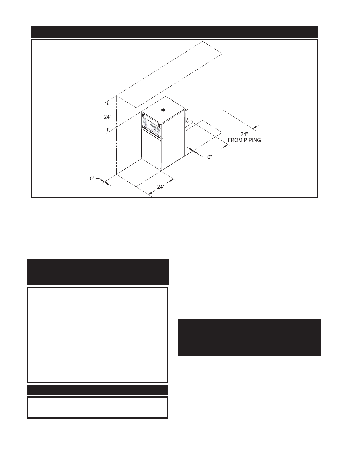
Maintain minimum specified clearances for adequate
operation. All installations must allow sufficient space for
servicing the vent connections, water pipe connections, piping
and other auxiliary equipment, as well as the
appliance. The clearance labels on each appliance note the
same service and combustible clearance requirements as shown
above.
Multiple appliances may be installed in a modular boiler or
water heater installation. Multiple appliances may be installed
side by side with no clearance between adjacent appliances
because this appliance is approved for zero clearance from
combustible surfaces and no service access is required from the
sides.
Provisions for combustion and ventilation air must be in
accordance with Section 5.3, Air for Combustion and
Ventilation, of the latest edition of the National Fuel Gas Code,
ANSI Z223.1, in Canada, the latest edition of CGA Standard
B149 Installation Code for Gas Burning Appliances and
Equipment, or applicable provisions of the local building
codes.
The equipment room MUST be provided with properly sized
openings to assure adequate combustion air and proper
ventilation.
COMBUSTION AND VENTILATION
AIR REQUIREMENTS FOR
APPLIANCES DRAWING AIR
FROM THE EQUIPMENT ROOM
Clearances from combustible construction are
noted on the appliance rating plate.
NOTE:
Right Side - 0"
Rear - 6" (15cm) (Minimum 24" (0.61m) suggested for
service to pump and components)
Left Side - 0"
Front - ALCOVE* (Minimum 24" (0.61m) suggested
for service)
Top - 6" (15cm) (Minimum 24" (0.61m) suggested for
service)
Flue - 2" (51mm)
Hot Water Pipes - 1" (25.4mm)
*An ALCOVE is a closet without a door.
TABLE — A
Clearances from Combustible
Construction:
4
CLEARANCES FROM COMBUSTIBLE CONSTRUCTION
FIG. 2 Clearances from Combustible Construction - Front & Rear View
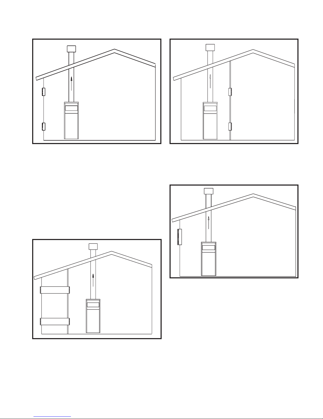
FIG. 3 Combustion Air Direct from Outside
1. If air is taken directly from outside the building with no
duct, provide two permanent openings:
a. Combustion air opening, with a minimum free area of
one square inch per 4000 Btu input (5.5 cm
2
per kW).
This opening must be located within 12" (30 cm) of the
bottom of the enclosure.
b. Ventilation air opening, with a minimum free area of
one square inch per 4000 Btu input (5.5 cm
2
per kW).
This opening must be located within 12 inches (30 cm)
of the top of the enclosure.
FIG. 4 Combustion Air Through Ducts
2. If combustion and ventilation air is taken from the outdoors
using a duct to deliver the air to the equipment room, each
of the two openings should be sized based on a minimum
free area of one square inch per 2000 Btu (11 cm
2
per kW)
of input.
FIG. 5 Combustion Air from Interior Space
3. If air is taken from another interior space, each of the two
openings specified above should have a net free area of one
square inch for each 1000 Btu (22 cm
2
per kW) of input, but
not less than 100 square inches (645 cm2).
FIG. 6 Combustion Air from Outside - Single Opening
4. If a single combustion air opening is provided to bring
combustion air in directly from the outdoors, the opening
must be sized based on a minimum free area of one square
inch per 3000 Btu (7 cm
2
per kW). This opening must be
located within 12 inches (30 cm) of the top of the enclosure.
All dimensions are based on net free area in square inches.
Metal louvers or screens reduce the free area of a combustion
air opening a minimum of approximately 25%. Check with
louver manufacturers for exact net free area of louvers. Where
two openings are provided, one must be within 12 inches (30
cm) of the ceiling and one must be within 12 inches (30 cm) of
the floor of the mechanical room. Each opening must have net
free area as specified in the chart on page 6. Single openings
shall commence within 12 inches (30 cm) of the ceiling.
5
6
The combustion air supply must be completely free of any
flammable vapors that may ignite or chemical fumes which
may be corrosive to the appliance. Common corrosive
chemical fumes which must be avoided are fluorocarbons and
other halogenated compounds, most commonly present as
refrigerants or solvents, such as Freon, trichlorethylene,
perchlorethylene, chlorine, etc. These chemicals, when burned,
form acids which quickly attack the heat exchanger finned
tubes, headers, flue collectors, and the vent system. The result
is improper combustion and a non-warrantable, premature
appliance failure.
5. A gas fired boiler, water heater, or combination of units may
be installed in an equipment room and have the required
combustion and ventilation air supplied by a mechanical
fan. The total Btu/hr input of all gas appliances in the
equipment room must be considered to properly size a
combustion air fan. Per the latest edition of the National
Fuel Gas Code, a fan used to mechanically supply air to the
equipment room must be sized to provide a minimum of
0.35 ft
3
per minute per 1000 Btu/hr of the total gas input in
the equipment room.
EXHAUST FANS: Any fan or equipment which exhausts air
from the equipment room may deplete the combustion air
supply and/or cause a down draft in the venting system.
Spillage of flue products from the venting system into an
occupied living space can cause a very hazardous condition that
must be immediately corrected. If a fan is used to supply
combustion air to the equipment room, the installer must make
sure that it does not cause drafts that could lead to nuisance
operational problems with the appliance.
The optional Direct Vent and DirectAire venting systems have
specific requirements for a special combustion air duct from the
outside that is directly connected to the appliance. See the
requirements for this combustion air duct in the venting section
for each specialized vent system.
Vent Options
This appliance has several vent options available depending on
the firing control of the unit
For units with on/off burner firing, the available venting
options are:
(1) Conventional Vertical Negative Draft Venting using a
Category I double-wall flue with a vertical rooftop termination
and combustion air supplied from the equipment room. These
units operate with on/off burner firing and are identified with an
“F” prefix on the firing controls.
(2) Vertical DirectAire Venting which uses a vertical negative
draft flue with a rooftop termination for flue products and a
combustion air pipe from the sidewall or rooftop.
For units that operate with modulating burner operation,
the available venting options are:
(1) Vertical Negative Draft Venting using a Category II
corrosion resistant flue with a vertical rooftop termination and
combustion air supplied from the equipment room. These units
operate with a modulating burner firing and are identified with
an “M” prefix on the firing controls.
(2) Sidewall Venting which uses which uses the unit’s internal
fan to exhaust the flue products out to a sidewall vent
VENTING
Under no circumstances should the mechanical room
ever be under a negative pressure. Particular care
should be taken where exhaust fans, attic fans, clothes
dryers, compressors, air handling units, etc., may take
away air from the unit.
CAUTION
COMBUSTION AIR SUPPLIED TO
THE EQUIPMENT ROOM BY A FAN
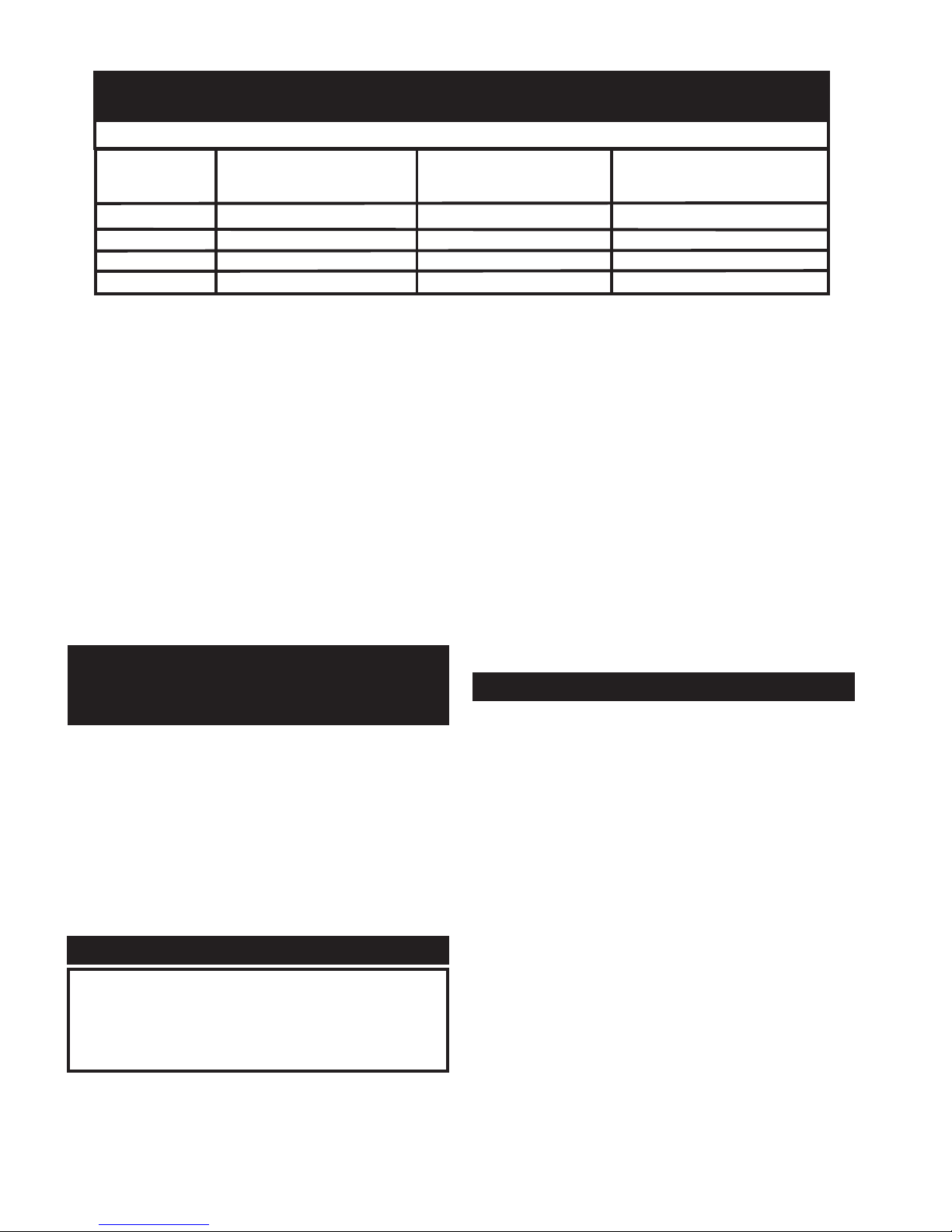
TABLE — B
Minimum Recommended Combustion Air Supply to Equipment Room
Boiler
Input
500,000
750,000
1,000,000
1,300,000
Outside Air*
2 - Openings
125 in
2
(806 cm2)
188 in2(1,213 cm2)
250 in2(1,613 cm2)
325 in2(2,097 cm2)
Outside Air*
1 - Opening
167 in
2
(1,077 cm2)
250 in2(1,613 cm2)
334 in2(2,155 cm2)
434 in2(2,800 cm2)
Inside Air
2 - Openings
(500 in
2
) (3,226 cm2)
(750 in2) (4,839 cm2)
(1000 in
2
) (6,452 cm2)
(1300 in
2
) (8,387 cm2)
COMBUSTION AIR SOURCE
*Outside air openings shall directly communicate with the outdoors. When combustion air is drawn from the outside
through a duct, the net free area of each of the two openings must have twice (2 times) the free area required for Outside
Air/2 Openings. The above requirements are for the boiler only; additional gas fired appliances in the equipment room
will require an increase in the net free area to supply adequate combustion air for all appliances. Combustion air
requirements are based on the latest edition of the National Fuel Gas Code, ANSI Z223.1; in Canada refer to the latest
edition of CGA Standard CAN B149.1 or .2. Check all local code requirements for combustion air.
termination with a sealed Category IV flue and combustion air
supplied from the equipment room.
(3) Vertical DirectAire Venting which uses a vertical negative
draft flue with a rooftop termination for flue products and a
combustion air pipe from the sidewall.
(4) Horizontal DirectAire Venting which uses the unit’s
internal fan to exhaust the flue products out a sidewall vent
termination with a sealed Category IV flue and a combustion
air pipe from the rooftop or from a sidewall other than the one
where the flue terminates.
(5) Direct Venting with a sealed Category IV flue and a
separate combustion air pipe to the outdoors. This system
terminates both the flue and combustion air inlet in the same
pressure zone. Both the flue outlet and combustion air intake
may terminate at either a sidewall (horizontal) or the rooftop
(vertical).
All units are shipped from the factory equipped for a vertical
negative draft venting system. All other optional vent systems
require the installation of specific vent kits and venting
materials. The following is a detailed explanation of the
installation requirements for each type of venting system,
components used, and part numbers of vent kits for each model.
General Venting Information
Vent installations for connection to gas vents or chimneys must
be in accordance with Part 7, “Venting of Equipment”, of the
latest edition of the National Fuel Gas Code, ANSI Z223.1, in
Canada, the latest edition of CAN/CGA Standard B149
Installation Code for Gas Burning Appliances and Equipment
or applicable provisions of the local building codes.
All venting applications where combustion air is drawn from
the equipment room must have adequate combustion and
ventilation air supplied to the equipment room in accordance
with the latest edition of the National Fuel Gas Code, ANSI
Z223.1, in Canada, the latest edition of CGA Standard B149
Installation Code for Gas Burning Appliances and Equipment,
or applicable provisions of the local building codes.
The distance of the vent terminal from adjacent buildings,
windows that open and building openings MUST comply with
the minimum clearances stated in this manual and the latest
edition of the National Fuel Gas Code, ANSI Z223.1, in
Canada, the latest edition of CAN/CGA Standard B149
Installation Code for Gas Burning Appliances and Equipment.
Vent connection is made directly to the flue outlet opening on
the back of the unit. The connection from the appliance vent to
the stack must be made as direct as possible with no reduction
in diameter.
Negative Draft General Venting Information
The negative draft in the flue of a Category I or II vent
installation must be within the range of a negative 0.02 to 0.08
inches water column to ensure proper operation. All draft
readings are made while the unit is in stable operation
(approximately 2 to 5 minutes). If draft exceeds the maximum
specified, a barometric damper must be installed to regulate
draft. Mount the barometric damper in the vertical flue at least
three feet above the connection to the unit’s flue outlet.
Use the National Fuel Gas Code venting tables to properly size
all vent connectors and stacks for all Category I and II systems.
The vent and accessories, such as firestop spacers, thimbles,
caps, etc., MUST be installed in accordance with the
manufacturer’s instructions. The vent connector and firestop
must provide correct spacing to combustible surfaces and seal
to the vent connector on the upper and lower sides of each floor
or ceiling through which the vent connector passes.
Any vent materials specified must be listed by a nationally
recognized test agency for use as vent material appropriate for
the specified vent category.
Follow the installation instructions from the manufacturer of
the vent material.
Locate units as close as possible to a chimney or gas vent.
When planning the venting system, avoid possible contact with
plumbing or electrical wiring inside walls, ceilings and floors.
Provide adequate clearance from combustibles for the vent
connector and firestop.
Avoid long horizontal runs of the vent pipe, 90° elbows,
reductions and restrictions. Horizontal portions of the venting
system shall be supported to prevent sagging.
Horizontal runs of vent pipe must slope upwards not less than
1/4 inch per foot (21 mm/m) from the appliance to the vent
terminal. Vent systems equipped with a drain tee must slope
upward from the drain to ensure proper removal of any
condensate that may form in the flue.
7
Examine the venting system at least once a year. Check all
joints and vent pipe connections for tightness. Also check
for corrosion or deterioration. Immediately correct any
problems observed in the venting system.
IMPORTANT
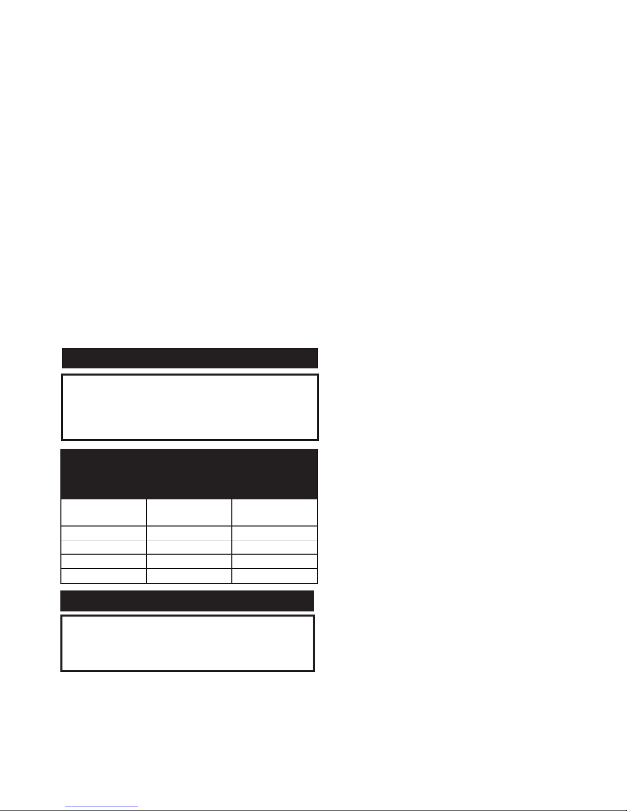
TABLE — C
Minimum Flue Pipe & Optional
Air Inlet Pipe Sizes are:
Input Btu/hr Flue Size
Air Inlet
Pipe Size
500,000 7" 5"
750,000 9" 5"
1,000,000 10" 6"
1,300,000 12" 6"
When the appliance is installed as either a Category II or
Category IV vent appliance, unique venting guidelines will
apply. Refer to the appropriate section of the Installation and
Service Manual for specific instructions for Category II or
Category IV vent installations.
WARNING
Category IV General Venting Information
A Category IV venting system operates with a positive pressure
in the vent. This positive pressure is generated by the internal
combustion air blower which operates the combustion process
and also exhaust the flue products from the building. The
Category IV flue from this appliance cannot be combined with
the vent from any other appliance. The Category IV flues from
multiple appliances cannot be combined into a common vent.
The Category IV flue from this appliance must be a dedicated
stack. The flue from this Category IV appliance must have all
vent joints and seams sealed gastight. A Category IV vent
system has specific vent material and installation requirements.
The flue products in the vent system may be cooled below their
dew point and form condensate in the flue. The flue materials
used for a Category IV vent must be resistant to any corrosive
damage from flue gas condensate. The flue from a Category IV
vent system must have a condensate drain with provisions to
properly collect and dispose of any condensate that may occur
in the venting system.
The connection from the appliance vent to the stack or vent
termination outside the building must be made with listed
Category IV vent material and must be as direct as possible.
The Category IV vent and accessories such as firestop spacers,
thimbles, caps, etc., must be installed in accordance with the
vent manufacturer’s instructions. The vent connector and
firestop must provide correct spacing to combustible surfaces
and seal to the vent connector on the upper and lower sides of
each floor or ceiling through which the vent connector passes.
Any vent materials specified must be listed by a nationally
recognized test agency for use as a Category IV vent material.
The venting system must be planned so as to avoid possible
contact with concealed plumbing or electrical wiring inside
walls, floors, or ceilings. Locate the appliance as close as
possible to a chimney or gas vent.
Horizontal portions of the venting system shall be supported to
prevent sagging. Horizontal runs should slope upwards not less
than 1/4 inch per foot from the drain tee installed in the flue to
the vertical portion of the flue or to the vent terminal on
sidewall venting installations. This ensures proper removal of
any condensate that may form in the flue. Follow the
installation instructions from the vent material manufacturer.
Do not use an existing chimney as a raceway if another
appliance or fireplace is vented through the chimney. The
weight of the venting system must not rest on the unit.
Adequate support of the venting system must be provided in
compliance with local codes and other applicable codes. All
connections should be secured and sealed per the vent
manufacturer’s specifications.
Vent connectors serving appliances vented by natural draft shall
not be connected to any portion of the Category IV positive
pressure vent system used by this appliance. Connection of a
negative draft flue into the positive pressure stack from this
appliance may cause flue products to be discharged into an
occupied living space causing serious health injury.
When a Category IV vent system is disconnected for any
reason, the flue must be reassembled and resealed according to
the vent manufacturer’s instructions.
The flue may terminate either vertically at the rooftop or
horizontally on a sidewall. Refer to the specific vent
termination sections for information about recommended vent
termination location and clearances.
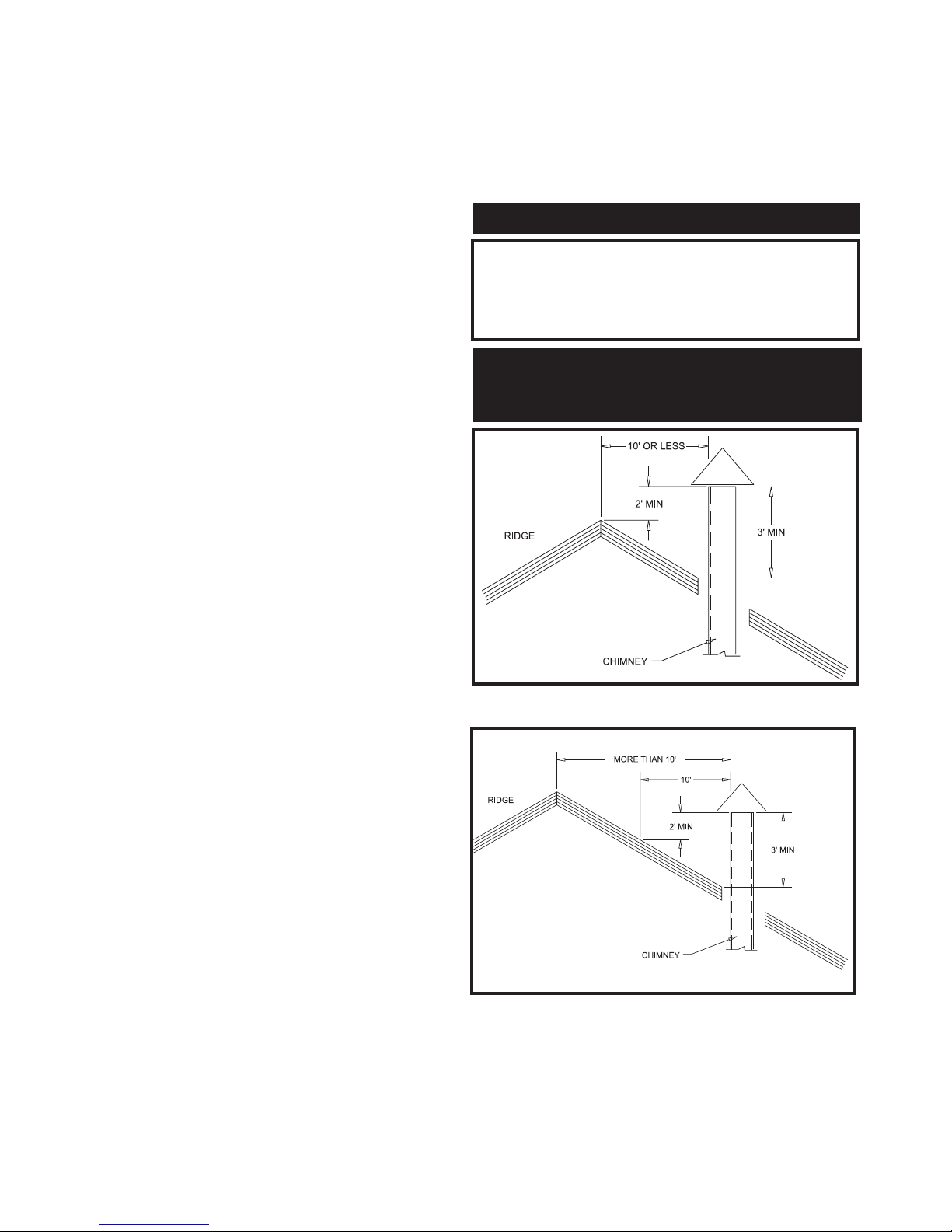
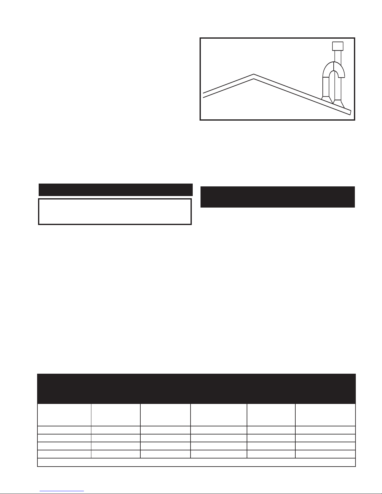
FIG. 7 Vent Termination from Peaked Roof - 10' or Less
from Ridge
FIG. 8 Vent Termination from Peaked Roof More than 10'
from Ridge
The vent terminal should be vertical and exhaust outside the
building at least 2 feet (0.61m) above the highest point of the
roof within a 10 foot (3.05m) radius of the termination.
The vertical termination must be a minimum of 3 feet (0.91m)
above the point of exit.
8
When the appliance is installed as either a Category II or
Category IV vent appliance, unique venting guidelines
will apply. Refer to the appropriate section of the
Installation and Service Manual for specific instructions
for Category II or Category IV vent installations.
WARNING
ROOFTOP VENT TERMINATION
CLEARANCES FOR CATEGORY I, II,
OR IV VERTICAL VENTING SYSTEMS
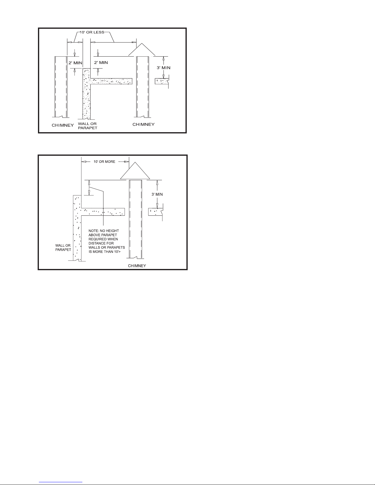
FIG. 9 Vent Termination from Flat Roof 10' or Less from
Parapet Wall
FIG. 10 Vent Termination from Flat Roof More Than 10'
from Parapet Wall
A vertical termination less than 10 feet (3.05m) from a parapet
wall must be a minimum of 2 feet (0.61m) higher than the
parapet wall.
The vent cap should have a minimum clearance of 4 feet
(1.22m) horizontally from and in no case above or below,
unless a 4 foot (1.22m) horizontal distance is maintained from
electric meters, gas meters, regulators, and relief equipment.
The venting system shall terminate at least 3 feet (0.9m) above
any forced air inlet within 10 feet (3.05m).
The venting system shall terminate at least 4 feet (1.2m) below,
4 feet (1.2m) horizontally from, or 1 foot (30cm) above any
door, window, or gravity air inlet into any building.
Do not terminate the vent in a window well, stairwell, alcove,
courtyard, or other recessed area. The vent cannot terminate
below grade. The bottom of the vent terminal shall be located
at least 12 inches (30cm) above the roof or above normal snow
levels.
To avoid a blocked flue condition, keep the vent cap clear of
snow, ice, leaves, debris, etc.
Flue gases from this appliance may contain large amounts of
water vapor that will form a white plume in winter. Plume
could obstruct window view.
Flue gas condensate can freeze on exterior surfaces or on the
vent cap. Frozen condensate on the vent cap can result in a
blocked flue condition. Flue gas condensate can cause
discoloration of exterior building surfaces. Adjacent brick or
masonry surfaces should be protected with a rust resistant sheet
metal plate.
The manufacturer shall NOT be held liable for any personal
injury or property damage due to ice formation or dislodging of
ice from the vent system or vent termination.
Common Venting Systems
When this appliance is equipped with ON/OFF burner firing
and a Category I flue, the flue may be combined with the flue
from any other negative draft, Category I appliance. Common
venting of multiple negative draft appliances requires that you
MUST install a barometric damper on each unit to regulate
draft. Install per the requirements of the latest edition of the
National Fuel Gas Code, ANSI Z223.1 and/or CAN/CGA-B149
Installation Code.
Common venting systems may be too large when an existing
unit is removed. At the time of removal of an existing
appliance, the following steps shall be followed with each
appliance remaining connected to the common venting system
placed in operation, while other appliances remaining
connected to the common venting system are not in operation.
a.) Seal any unused opening in the common venting system.
b.) Visually inspect the venting system for proper size and
horizontal pitch and determine there is no blockage or
restriction, leakage, corrosion, and other unsafe condition.
c.) Insofar as is practical, close all building doors and windows
and all doors between the space in which the appliances
remaining connected to the common venting system are
located and other spaces of the building. Turn on clothes
dryers and any other appliances not connected to the
common venting system. Turn on any exhaust fans, such
as range hoods and bathroom exhausts, so they will operate
at maximum speed. Do not operate a summer exhaust fan.
Close fireplace dampers.
d). Place in operation the appliance being inspected. Follow
the lighting instructions in this manual. Adjust thermostat
so appliance will operate continuously.
e.) Test for spillage at the draft hood / relief opening after five
(5) minutes of main burner operation. Use the flame of a
match or candle, or smoke from a cigarette, cigar, or pipe.
f.) After it has been determined that each appliance remaining
connected to the common venting system properly vents
when tested as above, return doors, windows, exhaust fans,
fireplace dampers, and other gas burning appliances to their
previous conditions of use.
g.) Any improper operation of the common venting system
should be corrected so that the installation conforms to the
latest edition of the National Fuel Gas Code, ANSI Z223.1,
in Canada, the latest edition of CGA Standard B149
Installation Code for Gas Burning Appliances and
Equipment. When resizing any portion of the common
venting system, the common venting system should be
9
resized to approach the minimum size as determined using
the appropriate tables in Appendix G in the latest edition of
the National Fuel Gas Code, ANSI Z223.1, in Canada, the
latest edition of CGA Standard B149 Installation Code for
Gas Burning Appliances and Equipment.
A masonry chimney must be properly sized and lined for the
installation of a high efficiency gas fired appliance. Venting of
a high efficiency appliance into a cold, oversized and unlined
masonry chimney can result in operational and safety problems.
A standard masonry chimney must not be used to vent the
products of combustion from this high efficiency gas fired
appliance.
A masonry chimney must be carefully inspected to determine
its suitability for the venting of flue products.
An unlined chimney must be relined with an approved chimney
liner system when a new appliance is being attached to it. For
appliances with ON/OFF burner firing, metallic liner systems
(Type “B” double-wall, flexible, or rigid metallic liners) are
recommended
For appliances with modulating burner operation, sealed,
metallic, corrosion resistant liner systems (single-wall, doublewall, flexible, or rigid metallic liners) rated for use with a high
efficiency, Category IV appliance must be used.
Corrosion resistant chimney liner systems are typically made
from a high grade of corrosion resistant stainless steel, such as
AL29-4C. The corrosion resistant liner must be properly sized
and fully sealed throughout the entire length contained within
the masonry lined chimney. Both the top and bottom of the
masonry chimney must be capped and sealed to provide a dead
air space around the liner.
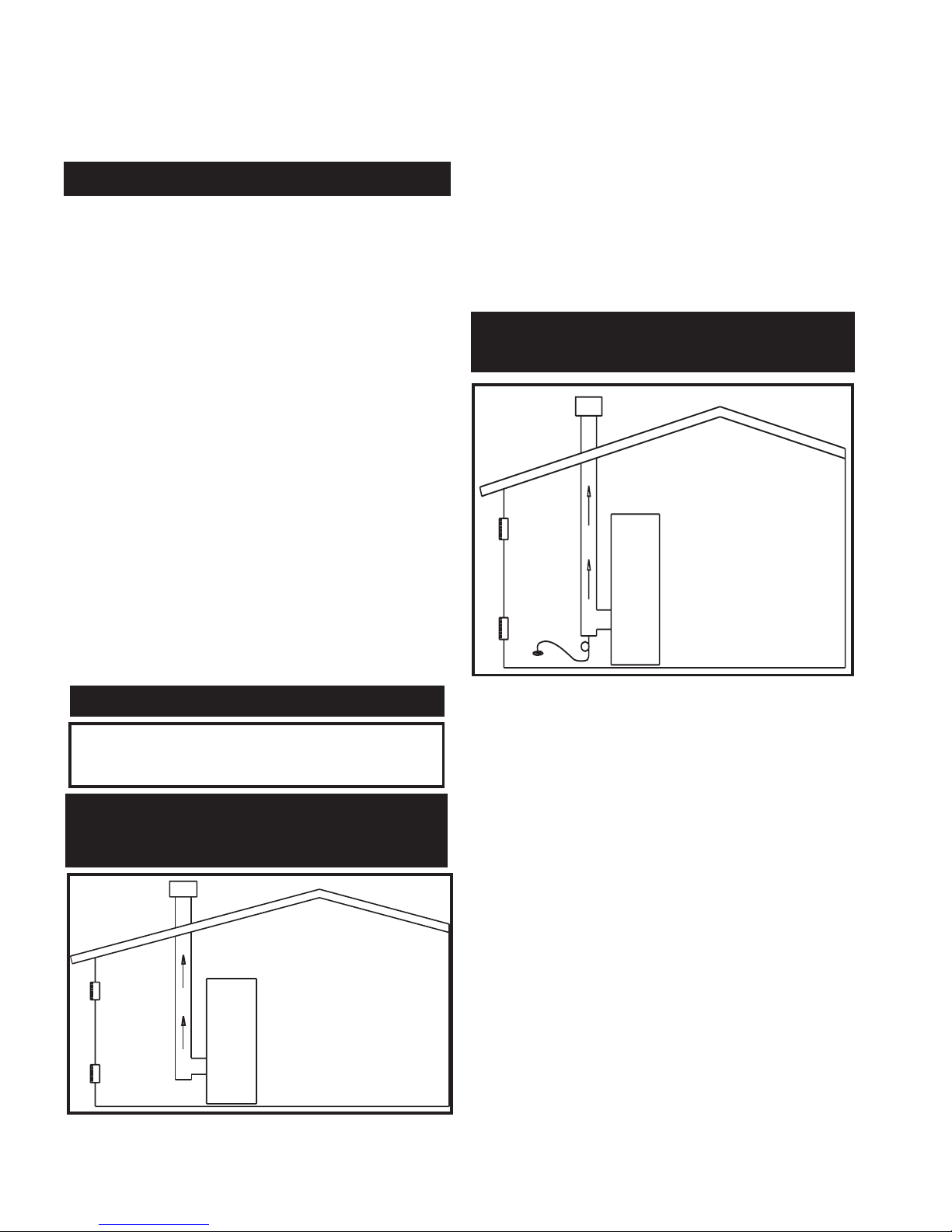
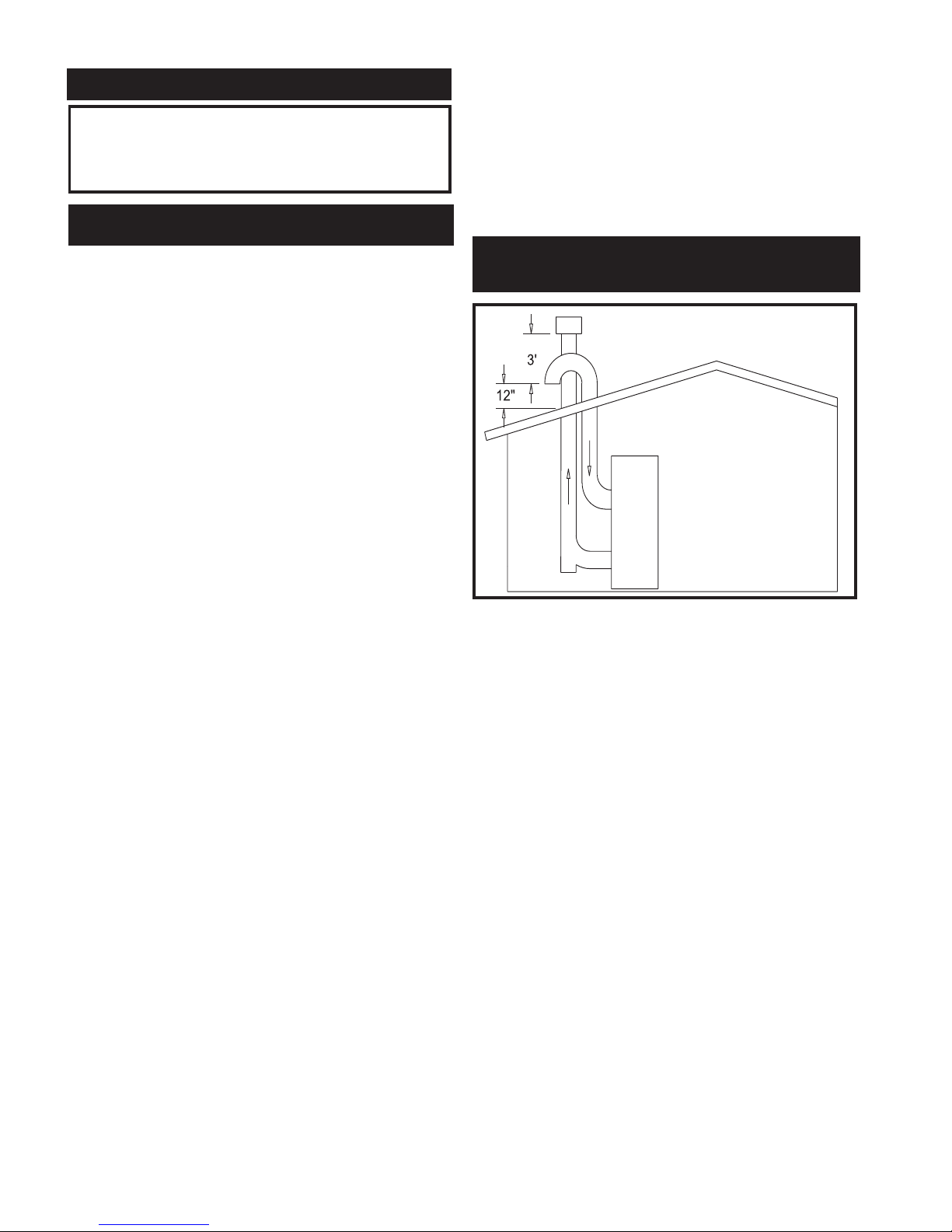
FIG. 11 Conventional Negative Draft Vertical Venting with
Combustion Air Supplied to the Equipment Room
Units that may be vented with a Category I, Type “B” vent
material operate with ON/OFF burner firing. A unit with
ON/OFF burner operation can be identified by the “Category I
and the “F” prefix on the firing controls as noted on the unit’s
rating plate. These are the only units that can be vented with
standard double-wall vent material. See the General Venting
and the Negative Draft General Venting Sections in this
manual. The flue must terminate at the rooftop. Combustion
air is supplied from the equipment room. The installation of the
vent must conform to the latest edition of the National Fuel Gas
Code, ANSI Z223.1, in Canada, the latest edition of CGA
Standard B149 Installation Code for Gas Burning Appliances
and Equipment.
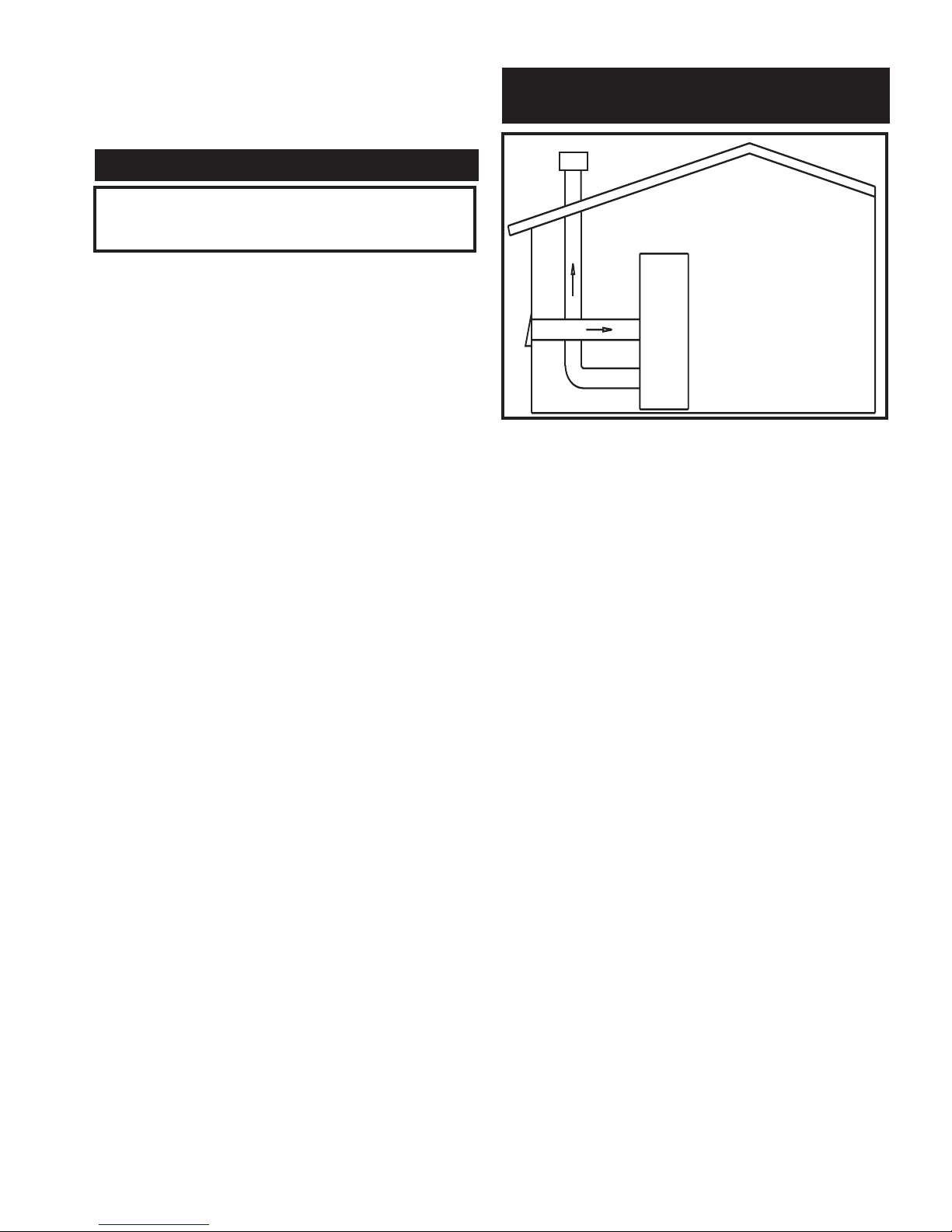
FIG. 12 Vertical Category II Negative Draft Venting with
Combustion Air Supplied to the Equipment Room
Units that must be vented with a Category II corrosion resistant
vent material operate with modulating burner firing. The unit
can be identified by the “Category II” and the “M” prefix on the
firing controls as noted on the unit’s rating plate. Vent
connection is made directly to the back of the unit using an
AL29-4C corrosion resistant vent pipe. See the General
Venting and the Negative Draft General Venting Sections in this
manual. The flue must terminate at the rooftop. Combustion
air is supplied from the equipment room. The modulating
burner may result in flue gas temperatures below their dew
point forming condensate in the flue. The vent materials must
be corrosion resistant. Materials used for a Category IV vent
are also corrosion resistant. The system must maintain a
negative draft within the specified range. Use a barometric
damper if system has excess draft.
Vent Materials: The connection from the vent to the stack or
vertical vent termination outside the building MUST be made
with a listed Category II corrosion resistant vent material (or
equivalent) and must be direct as possible with no reduction in
diameter. Currently there are not any vent manufacturers
producing Category II vent material, a Category IV vent
material may be used to meet material requirements for this
venting option.
10
CONVENTIONAL VERTICAL
CATEGORY I NEGATIVE DRAFT
VENTING SYSTEM
MASONRY CHIMNEY INSTALLATION
Check with local code officials to determine code
requirements or the advisability of using a masonry
chimney with a sealed corrosion resistant liner system.
IMPORTANT
(VERTICAL CATEGORY II NEGATIVE
DRAFT VENTING SYSTEM
Category IV Flue Pipe Materials
Select venting material from the following specified vent
distributors:
Heat-Fab Inc., Saf-T CI Vent with AL29-4C stainless steel
(Call 1-800-772-0739 for nearest distributor)
Protech Systems Inc., Fas N Seal Vent with AL29-4C stainless
steel (Call 1-800-766-3473 for nearest distributor)
Flex-L International Inc., StaR 34 Vent with AL29-4C
stainless steel (Call 1-800-561-1980 for nearest distributor)
Metal-Fab Inc., Corr/Guard Vent with AL29-4C stainless steel
(Call 1-800-835-2830 for nearest distributor)
Z-Flex Z-Vent with AL29-4C stainless steel (Call 1-800-6545600 for nearest distributor)
Or other listed Category IV vent systems suitable for a
condensing, positive pressure gas fired appliance.
A Category IV flue MUST have all vent joints and seams sealed
gastight and have provisions for a drain to properly collect and
dispose of condensate that may occur in the venting system.
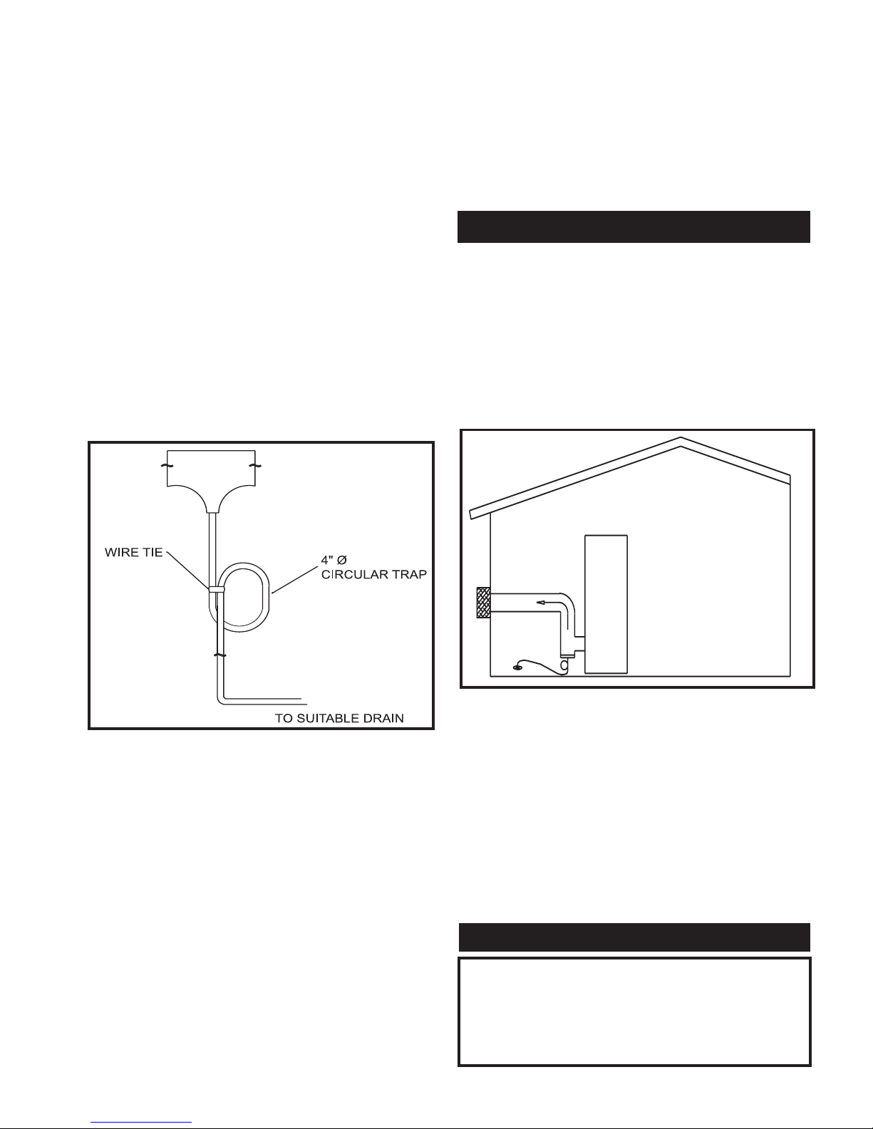
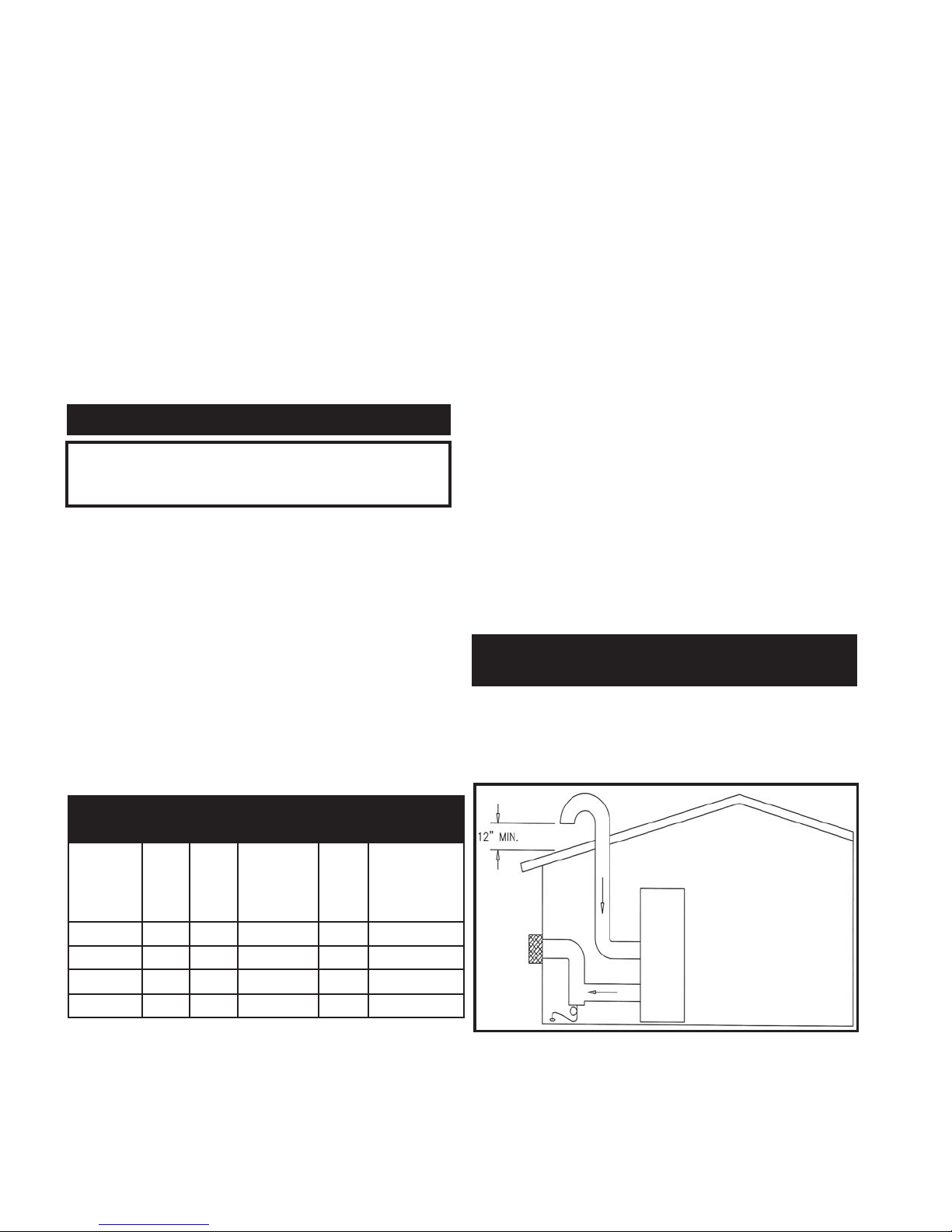
Drain Tee Installation
FIG. 13 Drain Tee Installed in Category II or IV Venting
The drain tee should be installed at the point where the flue
turns vertical for a rooftop termination or as one of the first
fittings in a horizontal flue connector that will terminate on a
sidewall. Ensure that horizontal portions of the vent are
properly sloped to allow condensate to be evacuated at the
drain tee. Plastic drain tubing, sized per the vent manufacturer’s
instructions, shall be provided as a drain line from the tee. The
drain tubing must have a trap provided by a 4" (10.2cm)
diameter circular trap loop in the drain tubing. Prime the trap
loop by pouring a small quantity of water into the drain hose
before assembly to the vent. Secure the trap loop in position
with nylon wire ties. Use caution not to collapse or restrict the
condensate drain line with the nylon wire ties. The condensate
drain must be routed to a condensate neutralization system or a
suitable drain for disposal. Ensure that the drain from the
condensate tee is not exposed to freezing temperatures. See
“Freeze Protection” for more information.
Common Venting System
You can combine the flue with the vent from other negative
draft Category II appliances ONLY. The vent from other
Category I appliances CANNOT be combined with the flue
from Category II appliances unless the entire vent system for
all units use Category IV vent materials. A barometric damper
must be installed on each unit when common venting multiple
negative draft Category II appliances.
This vent option is only available on units with modulating
burner firing. The unit can be identified by the “Category IV”
and the “M” prefix on the firing controls as noted on the unit’s
rating plate.
This venting system option uses the unit’s internal combustion
fan to force the flue products out of a sidewall vent cap
assembly. The unit’s internal fan generates a positive draft
pressure to exhaust the flue products. Combustion air is drawn
from the equipment room (see the Combustion and Ventilation
Air Requirements section).
FIG. 14 Sidewall Venting Installation
The connection from the appliance flue outlet to the sidewall
vent cap MUST be made with listed type Category IV vent
materials and accessories. See Category IV flue pipe material
specifications. The installer must supply suitable vent pipe
material. The sidewall vent cap is available from the appliance
manufacturer as a vent kit.
Alternate Sidewall Vent Kits with reduced vent sizes are also
approved and available from the manufacturer. These kits
include a vent reducer, as well as a reduced diameter vent cap.
See Table D for Standard and Alternate Sidewall Vent Kit
numbers. Each appliance must have a dedicated flue with no
other appliance interconnected to any part of the dedicated flue.
11
SIDEWALL VENTING
The Category IV flue from this appliance CANNOT be
combined with the vent from any other appliance. The
Category IV flue from this appliance must be a dedicated
stack and the flue from this appliance must have all vent
joints and seams sealed gastight. A Category IV vent system
has specific vent material and installation requirements.
WARNING
Maximum Vent Length
The installed length of the Category IV flue from the appliance
to the point of termination, outside of the building must not
exceed a maximum of 50 equivalent feet (15.2m) in length.
Subtract 5 feet (1.5m) of equivalent length for each 90° elbow
installed in the vent. Subtract 2 1/2 feet (0.7m) of equivalent
length for each 45° elbow installed in the vent.
All connections should be secured and sealed per the vent
manufacturer’s specifications.
Vent connectors serving appliances vented by natural draft shall
not be connected to any portion of the Category IV positive
pressure vent system used by this appliance. Connection of a
negative draft flue into the positive pressure stack from this
appliance may cause flue products to be discharged into an
occupied living space causing serious health injury.
When a Category IV vent system is disconnected for any
reason, the flue must be reassembled and resealed according to
the vent manufacturer’s instructions.
The flue for a sidewall venting system must terminate
horizontally on a sidewall. See specific information concerning
vent termination location for recommended clearances and
location.
The sidewall vent cap kit includes the wall penetration
assembly and the discharge screen assembly. All required
Category IV vent pipe and fittings must be purchased locally.
The installed sidewall vent cap assembly may be painted to
match the exterior décor.
The opening through the wall for installation of the sidewall
vent cap must provide an air space clearance of 2 inches
(5.1cm) around the flue pipe. The diameter of the opening for
installation of the sidewall cap will be 4 inches (10.2cm) larger
(minimum) than the nominal diameter of the installed vent pipe
to the sidewall cap.
The sidewall cap is installed from the outside and mounted to
the wall with four (4) screws or wall anchors. Seal under the
screw heads with caulking. Install the screen assembly using
the stainless steel screws provided in the kit. Install the
Category IV vent pipe from the appliance to the vent cap. The
installed vent pipe must protrude at least 2 inches (5.1cm) into
the screen area beyond the thimble portion of the sidewall cap
assembly. See detailed instructions packed with the sidewall
vent kit.
Follow all requirements in the Category IV General Venting
Information section for proper installation and for venting flue
products to the outdoors. See the Combustion and Ventilation
Air Requirements section to ensure that adequate combustion
and ventilation air is supplied to the equipment room. All other
general installation requirements must be followed.
Location of a Sidewall Vent Termination
Follow all requirements in the General Venting section.
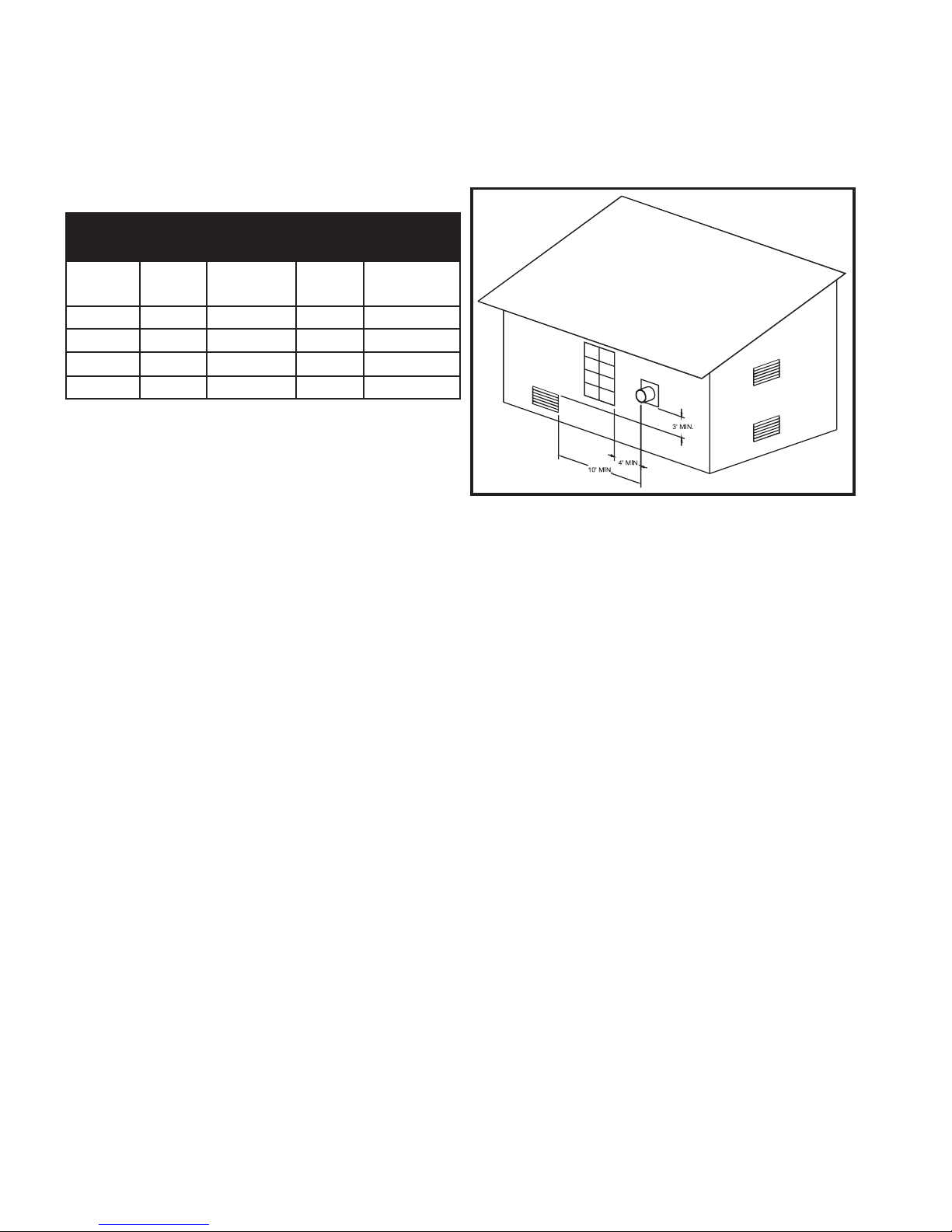
FIG. 15 Sidewall Venting Installation with Clearances from
Vent Cap
The vent cap shall terminate at least 3 feet (0.91m) above any
forced air inlet within 10 feet (3.05m).
The vent shall terminate at least 4 feet (1.22m) below, 4 feet
(1.22m) horizontally from or 1 foot (0.30m) above and 2 feet
(0.60m) horizontally from any door, window, or gravity air inlet
to the building.
The sidewall vent termination must be at least 8 feet (2.4m)
horizontally from any combustion air intake located above the
sidewall termination cap.
Do not terminate the vent in a window well, stairwell, alcove,
courtyard, or other recessed area. The vent cannot terminate
below grade.
The vent shall not terminate directly above a public walkway
due to the normal formation of water vapor in the combustion
process. Horizontal terminations must not be located over areas
of pedestrian or vehicular traffic.
The vent system shall terminate at least 1 foot (0.30m) above
grade, above normal snow levels and at least 7 feet (2.13m)
above grade when located adjacent to public walkways.
The vent terminal shall not be installed closer than 3 feet
(0.91m) from an inside corner of an L-shaped structure.
The vent cap should have a minimum clearance of 4 feet
(1.22m) horizontally from and in no case above or below,
unless a 4 foot (1.22m) horizontal distance is maintained from
electric meters, gas meters, regulators and relief equipment.
Flue gas condensate can freeze on exterior walls or on the vent
cap. Frozen condensate on the vent cap can result in a blocked
flue condition. Some discoloration to exterior building surfaces
can be expected. Adjacent brick or masonry surfaces should be
protected with a rust resistant sheet metal plate.
12
TABLE — D
Sidewall Vent Kits
Input
Btu/hr
Flue
Size
Sidewall
Vent Kit
Alt. Flue
Size
Alt. Sidewall
Vent Kit
500,000 7" SVK3027 4" SVK3056
750,000 9" SVK3049 5" SVK3057
1,000,000 10" SVK3029 6" SVK3058
1,300,000 12" SVK3050 8" SVK3059
The sidewall vent system must use the sidewall vent cap kit
provided by the appliance manufacturer for installation on a
sidewall termination.
The sidewall vent cap MUST be purchased as a kit from the
appliance manufacturer to ensure proper operation. Locally
purchased or fabricated sidewall vent caps should not be used.
Direct Vent and DirectAire Vent Systems are installed with
specific flue pipe material requirements based on the type of
firing controls used on the unit. Direct Vent and DirectAire
systems both use a separate combustion air pipe to the outdoors.
The Direct Vent System terminates both the flue and
combustion air inlet in the same pressure zone. The DirectAire
Vent System may terminate the flue and combustion air inlet in
different pressure zones. The flue outlet and combustion air
intake may terminate with either a sidewall or a rooftop
termination based on the specific venting option selected.
Follow all requirements for the specific venting option selected
to determine vent material requirements and proper installation
to discharge the flue products vertically or horizontally to the
outdoors. All other general installation requirements must be
followed.
The Direct Vent and DirectAire Vent Systems require the
installation of an additional pipe to supply combustion air from
outdoors directly to the appliance.
Length of Air Inlet Pipe
The maximum total length of the sidewall or vertical rooftop
combustion air inlet pipe as installed from the appliance to the
air inlet cap must not exceed 50 equivalent feet (15.2m) in
length. Subtract 5 feet (1.52m) of equivalent length for each
90° elbow installed in the air inlet pipe system. Subtract
2 1/2 feet (0.7m) of equivalent length for each 45° elbow
installed in the air inlet pipe system. Do not exceed limits for
the combustion air inlet piping lengths.
Air Inlet Pipe Materials
The air inlet pipe(s) must be sealed. Choose acceptable
combustion air inlet pipe materials from the following list:
PVC, CPVC or ABS (5" or 6" I.D.)*
Dryer Vent or Sealed Flexible Duct (not recommended
for rooftop air inlet)
Galvanized steel vent pipe with joints and seams
sealed as specified below.
Type “B” double-wall vent with joints and seams
sealed as specified below.
*Plastic pipe may require an adapter (not provided) to
transition between the air inlet connection on the
appliance and the plastic air inlet pipe.
Sealing of Type “B” double-wall vent material or galvanized
vent pipe material used for air inlet piping on a sidewall or
vertical rooftop Combustion Air Supply System:
a. Seal all joints and seams of the air inlet pipe using either
Aluminum Foil duct tape meeting UL Standard 723 or
181A-P or a high quality UL Listed silicone sealant such as
those manufactured by Dow Corning or General Electric.
b. Do not install seams of vent pipe on the bottom of horizontal
runs.
c. Secure all joints with a minimum of three sheet metal screws
or pop rivets. Apply Aluminum Foil duct tape or silicone
sealant to all screws or rivets installed in the vent pipe.
d. Ensure that the air inlet pipes are properly supported.
The PVC, CPVC, or ABS air inlet pipe should be cleaned and
sealed with the pipe manufacturer’s recommended solvents and
standard commercial pipe cement for the material used. The
PVC, CPVC, ABS, Dryer Vent or Flex Duct air inlet pipe
should use a silicone sealant to ensure a proper seal at the
appliance connection and the air inlet cap connection. Dryer
vent or flex duct should use a screw type clamp to seal the vent
to the appliance air inlet and the air inlet cap. Proper sealing of
the air inlet pipe ensures that combustion air will be free of
contaminants and supplied in proper volume.
When a sidewall or vertical rooftop combustion air supply
system is disconnected for any reason, the air inlet pipe must be
resealed to ensure that combustion air will be free of
contaminants and supplied in proper volume.
13
Appliances that are shut down or will not operate may
experience freezing due to convective airflow in the air inlet
pipe connected to the appliance.
WARNING
DIRECT VENT AND DIRECTAIRE
VENT SYSTEMS
When the appliance is installed as either a Category II or
Category IV vent appliance, unique venting guidelines will
apply. Refer to the appropriate section of the Installation and
Service Manual for specific instructions for Category II or
Category IV vent installations.
WARNING
Using vent or air intake materials other than those specified,
failure to properly seal all seams and joints or failure to
follow vent pipe manufacturer’s instructions can result in
personal injury, death or property damage. Mixing of
venting materials will void the warranty and certification of
the appliance.
WARNING
The use of double-wall vent or insulated material for the
combustion air inlet pipe is recommended in cold climates
to prevent the condensation of airborne moisture in the
incoming combustion air.
NOTE
A DirectAire vent system uses a flue to the sidewall or rooftop
with a separate combustion air pipe to the outdoors. The
DirectAire vent system may terminate the flue and the
combustion air inlet pipe in different pressure zones in any one
of four configurations. These are: (1) The flue on the rooftop
and combustion air intake on the sidewall. (2) Both the flue
and air inlet terminated on the rooftop using a Category I flue
for units with ON/OFF burner firing. (3) The flue terminated
on the sidewall and combustion air from the rooftop. (4) The
flue terminated on the sidewall and the combustion air intake
on a sidewall other than the sidewall where the flue is located.
All appliances are shipped from the factory with a flue outlet
that allows the connection of Category I or Category IV venting
systems. Check the vent category rating on your unit to ensure
that proper vent material is used. The optional DirectAire vent
systems require the installation of specific venting materials
that are purchased locally. Rooftop termination caps for flue
products and combustion air must be purchased locally.
Sidewall termination caps for flue products and combustion air
must be purchased from the manufacturer. The sidewall caps
for combustion air and flue products are available as vent kits.
The following is a detailed explanation of the installation
requirements for each venting system, components used, and
part numbers of vent kits for each model.
Follow all requirements for the type of vent materials used with
your unit.
A Category I or II vertical flue must follow the requirements in
the Vertical Negative Draft Venting sections. A Category IV
flue must follow the requirements under the Category IV
General Venting Information section. All other general venting
installation requirements must be followed.
The DirectAire vent system always requires the installation of
an additional pipe to supply combustion air from outdoors
directly to the appliance. The air inlet pipe must use one of the
materials specified in the Air Inlet Pipe Materials section.
Combined Combustion Air Inlet Points for DirectAire
Systems Only
The air inlet pipes from multiple appliances can be combined
to a single common connection if the common air inlet pipe has
a cross sectional area equal to or larger than the total area of all
air inlet pipes connected to the common air inlet pipe.
[Example: two 5" (12.7cm) air inlet pipes (19.63 in
2
(126.6 cm2) area each) have a total area of 39.26 in2(253.3 cm2)
requires an 8" (20.3 cm) (50.26 in2area) 324.3 cm2) common
air inlet pipe.] The air inlet point for multiple boiler air inlets
must be provided with an exterior opening which has a free
area equal to or greater than the total area of all air inlet pipes
connected to the common air inlet. This exterior opening for
combustion air must connect directly to the outdoors. The total
length of the combined air inlet pipe must not exceed a
maximum of 50 (15.2m) equivalent feet. You must deduct the
restriction in area provided by any screens, grills or louvers
installed in the common air inlet point. Screens, grills, or
louvers installed in the common air inlet can reduce the free
area of the opening from 25% to 75% based on the materials
used.
FIG. 16 Vertical DirectAire Installation with Rooftop
Combustion Air Inlet
This venting option is only for units that operate with single
stage ON/OFF burner firing. These units will be marked as
Category I and have an “F” prefix on the firing controls as
noted on the rating plate. This venting option uses a Category
I, Type “B” double-wall vent material terminated at the rooftop
and a separate combustion air pipe also terminating at the
rooftop. The flue must be installed per all requirements in the
Conventional Vertical Negative Draft Venting section for a
Category I vent. Follow all requirements in the Conventional
Vertical Negative Draft Venting section for the materials
required to ensure that flue products are properly vented
vertically to the outdoors. All other general installation
requirements must be followed. The flue outlet and
combustion air intake terminate in the same pressure zones, but
because of the use of a Category I flue it does not meet the
specifications for a Direct Vent System.
The maximum installed length of the flue pipe from the
appliance to the termination cap is limited only by the
requirement to maintain a negative draft within the limits
specified in the Negative Draft General Venting Information
section.
Air Inlet Pipe Materials
A DirectAire Vent System always requires the installation of an
additional pipe to supply combustion air from outdoors directly
to the appliance. The air inlet pipe must use one of the
materials specified in the Air Inlet Pipe Materials section.
14
Failure to properly seal all joints and seams as required in
the air inlet piping may result in flue gas recirculation,
spillage of flue products and carbon monoxide emissions
causing severe personal injury or death.
DANGER
DIRECTAIRE VENT SYSTEMS
VERTICAL DIRECTAIRE VENTING
WITH ROOFTOP COMBUSTION AIR
In cold climates, the use of Type “B” double-wall vent pipe or
an insulated single-wall pipe is recommended to help prevent
moisture in the cool incoming air from condensing and leaking
from the inlet pipe.
Vertical Combustion Air Inlet
The air inlet cap for the vertical rooftop inlet is assembled from
components purchased locally. The air inlet cap consists of two
90° elbows installed at the point of termination for the air inlet
pipe. The first 90° elbow is installed on the rooftop at the
highest vertical point of the air inlet pipe and turned horizontal;
the second 90° elbow is installed on the horizontal outlet of the
first elbow and turned down. A 90° elbow and a 90° street
elbow may be used to make this assembly. If a straight piece of
pipe is used between the two elbows, it should not exceed 6"
(51mm) in length. The termination ell on the air inlet must be
located a minimum of 12" (0.30m) above the roof or above
normal levels of snow accumulation.
Location of a Rooftop Air Inlet Cap
The point of termination for the combustion air inlet cap MUST
be at least 3 feet (0.91m) below any point of flue gas
termination (vent cap) if it is located within a 10 foot (3.05m)
radius of the flue outlet. Use care to ensure that the 90° ell
assembly is properly installed on the air inlet pipe. The
assembled combustion air cap assembly used MUST
adequately protect the combustion air inlet from wind and
weather.
The combustion air inlet cap must not be installed closer than
10 feet (3.05m) from an inside corner of an L-shaped structure.
The termination point of the combustion air inlet cap must be
installed at least one foot (0.30m) above the rooftop and above
normal snow levels.
The combustion air cap assembly used MUST adequately
protect the combustion air inlet from wind and weather.
Combustion air supplied from outdoors must be free of
contaminants (see Combustion and Ventilation Air). To prevent
recirculation of flue products into the combustion air inlet,
follow all instructions in this section.
Incorrect installation and/or location of the air inlet cap can
allow the discharge of flue products to be drawn into the
combustion process on the heater. This can result in incomplete
combustion and potentially hazardous levels of carbon
monoxide in the flue products. This will cause operational
problems with the heater and possible spillage of flue products
that can cause personal injury, death, or property damage.
For clearances between multiple air inlet caps, see the Multiple
Vertical Direct Vent Installation section.
FIG. 17 Vertical DirectAire Installation with Sidewall
Combustion Air Inlet
Vertical DirectAire vent systems are installed with the flue
terminating at the rooftop and a separate combustion air pipe at
the sidewall to the outdoors. The flue outlet and combustion air
intake terminate in different pressure zones.
Flue Requirements - ON/OFF Burner Operation
This unit, which operates with an on/off burner firing, may be
vented to the rooftop with a Type “B” vent material. These
units will be marked as Category I and have an “F” prefix on
the firing controls as noted on the rating plate. The flue must
be installed per all requirements in the Conventional Vertical
Negative Draft Venting section for a Category I vent. Follow all
requirements in the Conventional Vertical Negative Draft
Venting section for the materials required to ensure that flue
products are properly vented vertically to the outdoors. All
other general installation requirements must be followed.
Flue Requirements - Modulating Burner Operation
A unit, which operates with a modulating burner firing, may be
vented to the rooftop with a Category II vent material or
equivalent (Category IV) vent material. These units will be
marked as Category II and have an “M” prefix on the firing
controls as noted on the rating plate. The flue must be installed
per all requirements in the Vertical Category II Negative Draft
Venting section using a Category II corrosion resistant flue or
equivalent. Follow all requirements in the Vertical Category II
Negative Draft Venting section for the Category II materials
required to ensure that flue products are properly vented
vertically to the outdoors. All other general installation
requirements must be followed.
Alternate vertical venting with reduced vent sizes is also
approved by the manufacturer. Refer to Table E - Vertical
DirectAire Vent Kits for the alternate flue sizes approved and
the vent reducer part number available from the manufacturer.
When using the reduced vent size the vent will become a
positive pressure vent requiring the use of Category IV vent
material. Follow all requirements in the Category IV General
Venting Information section for proper installation and for
15
Appliances that are shut down or will not operate may
experience freezing due to convective airflow in the air inlet
pipe connected to the appliance.
CAUTION
VERTICAL DIRECTAIRE WITH
SIDEWALL COMBUSTION AIR
venting flue products to the outdoors. All other general
installation requirements must be followed.
The maximum installed length of the Category IV flue from the
appliance to the point of termination must not exceed 50
equivalent feet in length. Subtract 5 feet of equivalent length
for each 90° elbow installed in the vent. Subtract 2 1/2 feet of
equivalent length for each 45° elbow installed in the vent.
Air Inlet Pipe Materials
A DirectAire Vent System always requires the installation of an
additional pipe to supply combustion air from outdoors directly
to the appliance. The air inlet pipe must use one of the
materials specified in the Air Inlet Pipe Materials section.
In cold climates, the use of Type “B” double-wall vent pipe or
an insulated single-wall pipe is recommended to help prevent
moisture in the cool incoming air from condensing and leaking
from the inlet pipe.
Sidewall Combustion Air Inlet
The air inlet cap for the sidewall air inlet must be purchased
from the appliance manufacturer.
The part numbers for the required sidewall air inlet cap kit are
listed by unit size. The appliance manufacturer, in accordance
with CSA International/CGA requirements, must furnish the
sidewall air inlet cap. Each kit includes the special combustion
air inlet cap for installation on an exterior sidewall for
operation of a single appliance only.
Flue piping from the appliance to the rooftop termination may
be increased to 8 inches or 10 inches based on field availability
of 7 inch and 9 inch flue material.
Location of a Sidewall Air Inlet Ca\p
Incorrect installation and/or location of the air inlet cap can
allow the discharge of flue products to be drawn into the
combustion process on the heater. This can result in incomplete
combustion and potentially hazardous levels of carbon
monoxide in the flue products. This will cause operational
problems with the heater and possible spillage of flue products
that can cause personal injury, death, or property damage.
The termination point of the sidewall air inlet must be installed
a minimum of 12 inches (0.30m) above ground level and above
normal levels of snow accumulation.
The point of termination for the sidewall combustion air inlet
cap MUST be located a minimum of 3 feet (0.91m)
horizontally and 12 inches (0.30m) below any point of flue gas
termination (vent cap) if it is located within a 10 foot (3.05m)
radius of the flue outlet.
The sidewall combustion air inlet cap MUST NOT be installed
above the sidewall flue outlet if it is located within a 10 foot
(3.05m) radius of the flue outlet.
The sidewall combustion air inlet cap must not be installed
closer than 10 feet (3.05m) from an inside corner of an
L-shaped structure.
The sidewall combustion air cap assembly used MUST
adequately protect the combustion air inlet from wind and
weather.
The sidewall combustion air inlet cap and the rooftop flue gas
outlet are located in different pressure zones in a DirectAire
system.
Combustion air supplied from outdoors must be free of
contaminants (see Combustion and Ventilation Air). To prevent
recirculation of flue products into the combustion air inlet,
follow all instructions in this section.
For clearances between multiple vent caps, see the Multiple
Horizontal Direct Vent Installation section.
This vent option is only available on units with modulating
burner firing. The unit can be identified by the “Category IV”
and the “M” prefix on the firing controls as noted on the unit’s
rating plate.
FIG. 18 Horizontal DirectAire Installation with Rooftop
Combustion Air Inlet
The Horizontal DirectAire System terminates the flue at the
sidewall using Category IV vent materials and a combustion air
inlet pipe to draw air from the rooftop. Horizontal DirectAire
16
Appliances that are shut down or will not operate may
experience freezing due to convective airflow in the air inlet
pipe connected to the appliance.
CAUTION
TABLE — E
Vertical DirectAire Vent Kits
Input
Btu/hr
Flue
Size
Alt.
Flue
Vent
Reducer
Alt.
Inlet
Pipe
Size
DirectAire
Inlet
Sidewall
Cap Size Kit
500,000 7" 4" DRH2435 5" SAK3003
750,000 9" 5" DRH2436 5" SAK3003
1,000,000 10" 6" DRH2437 6" SAK3000
1,300,000 12" 8" DRH2438 6" SAK3000
HORIZONTAL DIRECTAIRE WITH
VERTICAL COMBUSTION AIR
Vent Systems are installed with the flue outlet and combustion
air intake located in different pressure zones.
Follow all requirements in the Sidewall Venting and
Category IV General Venting Information sections for proper
installation and for venting flue products horizontally out a
sidewall to the outdoors. All other general installation
requirements must be followed.
Air Inlet Pipe Materials
A DirectAire Vent System always requires the installation of an
additional pipe to supply combustion air from outdoors directly
to the appliance. The air inlet pipe must use one of the
materials specified in the “Air Inlet Pipe Materials” section.
In cold climates, the use of Type “B” double-wall vent pipe or
an insulated single-wall pipe is recommended to help prevent
moisture in the cool incoming air from condensing and leaking
from the inlet pipe.
The termination point for the flue products must follow the
clearance requirements in the Sidewall Venting section for use
with Category IV venting.
The flue and air inlet duct sizes for a Horizontal DirectAire
Installation with Rooftop Combustion Air Inlet are listed by
unit size. The sidewall vent cap must be purchased from the
appliance manufacturer as a vent kit. This venting option uses
the sidewall venting kit with the combustion air inlet system
constructed from materials purchased locally by the installer.
Alternate sidewall vent kits with reduced vent sizes are also
approved and available from the manufacturer. These kits
include a vent reducer, as well as a reduced diameter vent cap.
See Table F for Standard and Alternate Sidewall Vent Kit
numbers. All required Category IV vent pipe and fittings must
be purchased locally. The installed sidewall vent cap assembly
may be painted to match the exterior dècor.
Vertical Combustion Air Inlet
FIG. 19 Air Inlet Cap for Rooftop Termination
Follow the vertical combustion air inlet material and location
requirements as listed in the Vertical DirectAire Venting and
Rooftop Combustion Air section.
The rooftop combustion air inlet cap and the sidewall flue gas
outlet are located in different pressure zones in a DirectAire
Vent System.
This vent option is only available on units with modulating
burner firing. The unit can be identified by the “Category IV”
and the “M” prefix on the firing controls as noted on the unit’s
rating plate.
This vent system is installed with a Category IV flue and a
separate combustion air pipe to the outdoors. The Horizontal
DirectAire System terminates the flue at the sidewall and the
combustion air on a sidewall other than the sidewall where the
flue is located. The sidewall flue outlet and sidewall
combustion air intake terminate in different pressure zones.
17
Appliances that are shut down or will not operate may
experience freezing due to convective airflow in the air inlet
pipe connected to the appliance.
CAUTION
TABLE — F
Sidewall Vent Cap Kit for use with DirectAire with Rooftop Combustion Air
Input Btu/hr
Sidewall Flue
Size
Vertical Air Inlet
Pipe Size
Sidewall Vent Kit Alt. Flue Size
Alt. Sidewall
Vent Kit
500,000 7" 5" SVK3027 4" SVK3056
750,000 9" 5" SVK3049 5" SVK3057
1,000,000 10" 6" SVK3029 6" SVK3058
1,300,000 12" 6" SVK3050 8" SVK3059
The sidewall vent cap kit includes the wall penetration assembly and the discharge screen assembly.
HORIZONTAL DIRECTAIRE WITH
SIDEWALL COMBUSTION AIR
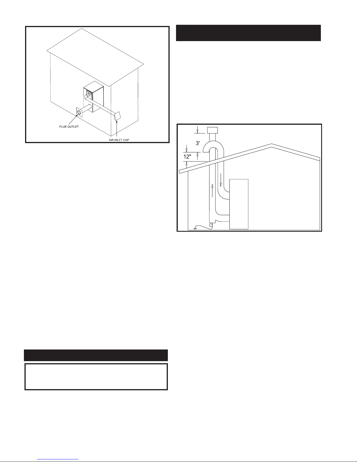
FIG. 20 Horizontal DirectAire Installation with Sidewall
Combustion Air in a Different Pressure Zone
Follow all requirements in the Sidewall Venting and Category
IV General Venting Information sections for proper installation
and for venting flue products horizontally out a sidewall to the
outdoors. All other general installation requirements must be
followed.
Air Inlet Materials
A DirectAire Vent System always requires the installation of an
additional pipe to supply combustion air from outdoors directly
to the appliance. The air inlet pipe must use one of the materials
specified in the Air Inlet Pipe Materials section.
In cold climates, the use of Type “B” double-wall vent pipe or
an insulated single-wall pipe is recommended to help prevent
moisture in cool incoming air from condensing and leaking
from the inlet pipe.
The maximum installed length of the air inlet pipe from the
appliance to the air inlet cap is 50 equivalent feet (15.2m) in
length. The maximum installed length of the flue pipe from the
appliance to the termination cap is 50 equivalent feet (15.2m) in
length. Subtract 5 feet (1.52m) of equivalent length for each
90° elbow installed in either the flue pipe or the air inlet pipe.
The termination point of the flue and air inlet must follow the
clearance requirements in the Sidewall Venting and Horizontal
Direct Vent sections.
This vent option is only available on units with modulating
burner firing. The unit can be identified by the “Category IV”
and the “M” prefix on the firing controls as noted on the unit’s
rating plate.
A Vertical Direct Vent System is installed with a Category IV
flue and a separate combustion air pipe to the outdoors. The
Direct Vent System terminates both the flue and air inlet in the
same pressure zone. The combustion air cap and flue gas outlet
MUST be located on the same rooftop surface and in the same
pressure zone.
FIG. 21 Vertical Direct Vent Installation with Rooftop
Combustion Air Inlet
Follow all requirements in the Category IV General Venting
Information section for proper installation and for venting flue
products vertically to the outdoors. All other general
installation requirements must be followed.
Alternate Vertical Venting with reduced vent sizes are also
approved by the manufacturer. Refer to the Vertical DirectAire
Table for the alternate flue sizes approved and the vent reducer
part number available from the manufacturer. Use the
appropriate Category IV venting materials to ensure that flue
products are properly vented vertically to the outdoors.
The Direct Vent System always requires the installation of an
additional pipe to supply combustion air from outdoors directly
to the appliance. The air inlet pipe must use one of the materials
specified in the Air Inlet Pipe Materials section.
The maximum installed length of the air inlet pipe from the
appliance to the air inlet cap is 50 equivalent feet (15.2m) in
length. The maximum installed length of the flue pipe from the
appliance to the termination cap is 50 equivalent feet (15.2m) in
length. Subtract 5 feet (1.52m) of equivalent length for each
90° elbow installed in either the flue pipe or the air inlet pipe.
The termination point for the flue products must follow the
clearance requirements in the Rooftop Vent Termination
Clearances for Category I, II, or IV Vertical Venting Systems.
18
Appliances that are shut down or will not operate may
experience freezing due to convective airflow in the air inlet
pipe connected to the appliance.
CAUTION
VERTICAL DIRECT VENT SYSTEMS
 Loading...