

Lochinvar Crest 1.5, Crest 2.5, Crest 2.0, Crest 3.0, Crest 3.5 Installation Instructions Manual
...Page 1
98624665
INS90011 Rev B
INSTALLATION INSTRUCTIONS
GRUNDFOS MAGNA 3 VARIABLE SPEED PUMP WITH LOCHINVAR BOILERS
FOR CREST 1.5 - 5.0 AND KNIGHT 400 - 801
Installation and Setup Procedure
1. Refer to the installation manual provided by the pump
manufacturer to install the pump. NOTE: The boiler
MUST be installed in the Primary / Secondary piping
configuration. Refer to the installation and operation
manual provided by the boiler manufacturer to ensure the
proper system piping configuration.
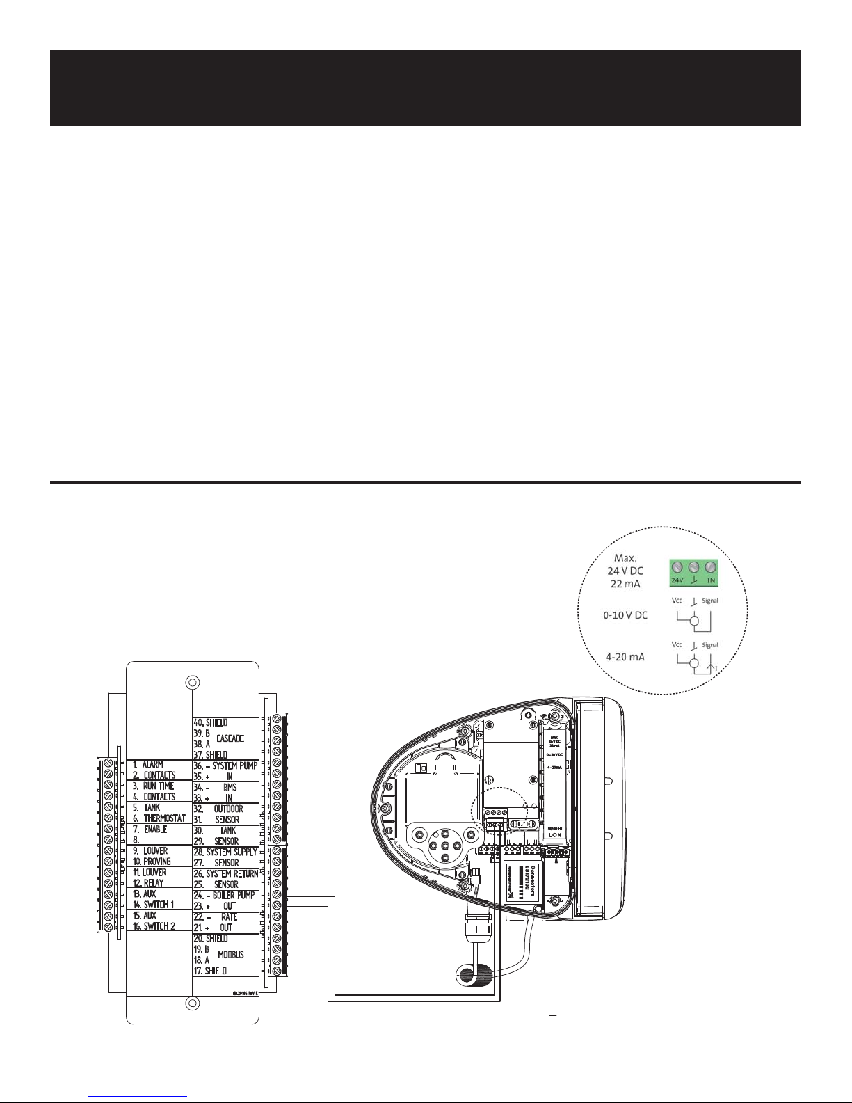
2. Reference FIG. 1 to connect wiring to the boiler’s low
voltage control board on the “Boiler Pump Out” terminal:
a. Connect the (+) wire from the boiler to “In”
connection on the pump 0-10V wiring terminal.
b. Connect the (-) wire from the boiler to the ground
terminal on the pump 0-10V wiring terminal.
3. Connect line voltage to the pump as shown in the
“Wiring” section of the boiler installation manual.
4. Reference Tables 1A and 1B on this instruction sheet to
determine the setpoint percentage of the pump.
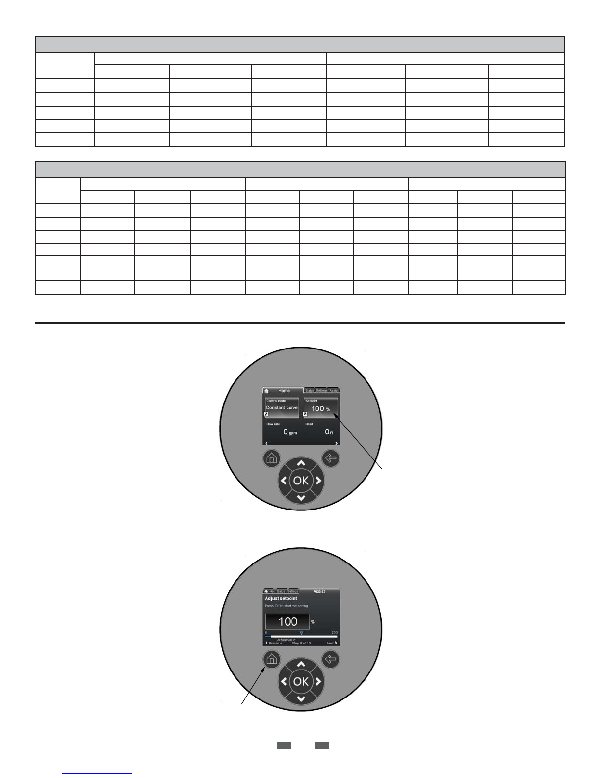
5. Follow the procedure below to apply the pump setpoint:
a) From the pump Home screen use the arrow keys to
select “Setpoint”.
b) Select “OK” to go to the Setpoint screen.
c) Use the arrow keys to to assign a setpoint based on the
information provided in FIG. 2, on page 2.
d) Select “OK” to save the setting.
e) Select the “Home” button to return to the Home
screen.
6. The pump is pre-programmed for 0-10V operation, but
the boiler will require set-up to control the variable speed
pump. Follow the instructions for variable speed pump
setup in the boiler installation manual.
Figure 1 Wiring Connections
DETAIL A
A
IMG00960
POWER CONNEC TION
Page 2
98624665
TABLE 1A - KNIGHT XL TEMPERATURE RISE APPLICATIONS
Model
400 37 40-80 92 30 40-80 75
501 46 50-150 42 37 50-150 83
601 55 50-150 79 44 50-150 67
701 65 50-150 79 52 50-150 64
801 74 50-150 100 60 50-150 69
GPM Magna 3 Setpoint % GPM Magna 3 Setpoint %
20°F25°F
TABLE 1B - CREST TEMPERATURE RISE APPLICATIONS
Model
1.5 138 50-150 71 69 40-80 86 46 40-80 58
2.0 184 80-100 67 92 50-150 46 61 40-80 76
2.5 230 80-100 82 115 50-150 57 77 40-80 96
3.0
3.5 323 100-120 97 161 50-150 81 108 50-150 59
4.0 248* 80-100 87 186 80-100 64 124 50-150 61
5.0 310* 100-120 92 233 80-100 79 155 50-150 77
*Based on 30°F Temperature Rise
GPM Magna 3 Setpoint % GPM Magna 3 Setpoint % GPM Magna 3 Setpoint %
277 80-100 97 138 50-150 69 92 50-150 46
20°F40°F60°F
Figure 2 Pump Setpoint Screens
SETPOINT
MENU
BUTTON
INS90011 Rev B
HOME
Revision Notes: Revision A
(ECO C14573) initial release.
Revision B (ECO C14859)
IMG00961
reflects the update of Table
1A, Table 1B and other text
adjustments.
2
04/14 - Printed in U.S.A.
 Loading...