

Page 1

INSTALLATION AND SERVICE MANUAL
Save this manual for future reference.
WARNING: If the
information in this manual
is not followed exactly, a
fire or explosion may
result causing property
damage, personal injury or
loss of life.
– Do not store or use
gasoline or other
flammable vapors and
liquids in the vicinity of
this or any other appliance.
WHAT TO DO IF YOU SMELL
GAS
• Do not try to light any
appliance.
• Do not touch any
electric switch; do not
use any phone in your
building.
• Immediately call your
gas supplier from a
neighbors phone.
Follow the gas
supplier’s instructions.
• If you cannot reach your
gas supplier, call the fire
department.
– Installation and service
must be performed by a
qualified installer, service
agency or the gas supplier.
WARNING: Do not use
this appliance if any part
has been under water. The
possible damage to a
flooded appliance can be
extensive and present
numerous safety hazards.
Any appliance that has
been under water must be
replaced.
HYDRONIC HEATING BOILERS and
DOMESTIC WATER HEATERS
399,999 - 2,070,000 Btu/hr MODELS
CF-CH(E)-i&s-08
WARNING: Improper
installation, adjustment,
alteration, service or
maintenance can cause
property damage, personal
injury, exposure to
hazardous materials or
loss of life. Refer to this
manual. Installation and
service must be performed
by a qualified installer,
service agency or the gas
supplier. This unit contains
materials that have been
identified as carcinogenic,
or possibly carcinogenic,
to humans.
Page 2

Hydronic Heating Boilers and
Domestic Water Heaters
2
Table of Contents
General Product Information . . . . . . . . . . . . . . . . . . . . . . . . .3
Special Instructions . . . . . . . . . . . . . . . . . . . . . . . . . . . . .3
Unpacking . . . . . . . . . . . . . . . . . . . . . . . . . . . . . . . . . . . .3
Codes . . . . . . . . . . . . . . . . . . . . . . . . . . . . . . . . . . . . . . . .3
Warranty . . . . . . . . . . . . . . . . . . . . . . . . . . . . . . . . . . . . .3
Safety Information . . . . . . . . . . . . . . . . . . . . . . . . . . . . . . . . .4
Product Identification . . . . . . . . . . . . . . . . . . . . . . . . . . . . . .5
Installation . . . . . . . . . . . . . . . . . . . . . . . . . . . . . . . . . . . . . . .6
Locating Unit . . . . . . . . . . . . . . . . . . . . . . . . . . . . . . . . .6
Clearances from Combustible Construction . . . . . . . . . .6
Base for Combustible Floors . . . . . . . . . . . . . . . . . . . . .7
Freeze Protection . . . . . . . . . . . . . . . . . . . . . . . . . . . . . . . . . .7
Pump Operation . . . . . . . . . . . . . . . . . . . . . . . . . . . . . . .7
Location . . . . . . . . . . . . . . . . . . . . . . . . . . . . . . . . . . . . .7
Hydronic System Antifreeze . . . . . . . . . . . . . . . . . . . . . .7
Outdoor Boiler Installation . . . . . . . . . . . . . . . . . . . . . . .7
Shutdown and Draining . . . . . . . . . . . . . . . . . . . . . . . . .8
Freeze Protection for a Heating Boiler System . . . . . . . . . . .8
Combustion and Ventilation Air . . . . . . . . . . . . . . . . . . .8
Combustion Air Filter . . . . . . . . . . . . . . . . . . . . . . . . . . .8
Combustion Air Options . . . . . . . . . . . . . . . . . . . . . . . . .9
Exhaust Fans . . . . . . . . . . . . . . . . . . . . . . . . . . . . . . . . .11
Venting . . . . . . . . . . . . . . . . . . . . . . . . . . . . . . . . . . . . . . . . .11
General Information . . . . . . . . . . . . . . . . . . . . . . . . . . .11
Venting Support . . . . . . . . . . . . . . . . . . . . . . . . . . . . . .11
Vertical Vent Termination Clearances and Location . .11
Sidewall Vent Termination Clearances and Location . .12
Combustion Air Inlet Piping . . . . . . . . . . . . . . . . . . . . .13
Combined Air Inlet Points . . . . . . . . . . . . . . . . . . . . . .15
Vent System Options . . . . . . . . . . . . . . . . . . . . . . . . . . . . . .15
Barometric Damper Location . . . . . . . . . . . . . . . . . . . .15
1. Conventional Negative Draft Venting . . . . . . . . . . .16
2. Vertical DirectAire
™
Venting . . . . . . . . . . . . . . . . . . .17
3. Sidewall Venting . . . . . . . . . . . . . . . . . . . . . . . . . . . .19
4. Horizontal DirectAire
™
Venting . . . . . . . . . . . . . . . .21
5. Direct Venting . . . . . . . . . . . . . . . . . . . . . . . . . . . . . .22
6. Outdoor Installation Venting . . . . . . . . . . . . . . . . . .26
Connecting to Gas Supply . . . . . . . . . . . . . . . . . . . . . . . . . .28
Gas Pressure Test . . . . . . . . . . . . . . . . . . . . . . . . . . . . .28
Gas Piping . . . . . . . . . . . . . . . . . . . . . . . . . . . . . . . . . . .28
Connecting Gas Piping to Unit . . . . . . . . . . . . . . . . . . .28
Gas Train and Controls . . . . . . . . . . . . . . . . . . . . . . . . .29
Combination Gas Valves . . . . . . . . . . . . . . . . . . . . . . .30
Venting of Combination Gas Valves . . . . . . . . . . . . . .30
Checking Gas Supply Pressure . . . . . . . . . . . . . . . . . . .30
Gas Manifold Pressure Adjustment . . . . . . . . . . . . . . .31
Connecting to Water Supply . . . . . . . . . . . . . . . . . . . . . . . .32
Inlet and Outlet Connections . . . . . . . . . . . . . . . . . . . .32
Relief Valve . . . . . . . . . . . . . . . . . . . . . . . . . . . . . . . . .33
Water Flow Switch . . . . . . . . . . . . . . . . . . . . . . . . . . . .33
Low Water Cutoff . . . . . . . . . . . . . . . . . . . . . . . . . . . . .33
Connecting to Electrical Supply . . . . . . . . . . . . . . . . . . . . .33
Boiler System Piping . . . . . . . . . . . . . . . . . . . . . . . . . . . . . .34
Primary/Secondary Boiler Piping . . . . . . . . . . . . . . . . .35
Table of Contents
Low Temperature Return Water Systems . . . . . . . . . . .36
Radiant Floor and Snow Melt Heating Systems . . . . . .37
Boiler Flow Rate . . . . . . . . . . . . . . . . . . . . . . . . . . . . . .38
Boiler Bypass Requirements . . . . . . . . . . . . . . . . . . . . .38
Temperature/Pressure Gauge . . . . . . . . . . . . . . . . . . . . .38
Placing the Boiler in Operation . . . . . . . . . . . . . . . . . . .38
Installation with a Chilled Water System . . . . . . . . . . .39
Boiler Operating Temperature Control . . . . . . . . . . . . .39
Water Treatment . . . . . . . . . . . . . . . . . . . . . . . . . . . . . . . . . .40
Terminal Strip Connection Options . . . . . . . . . . . . . . .40
Operation . . . . . . . . . . . . . . . . . . . . . . . . . . . . . . . . . . . . . . .41
Lighting Instructions . . . . . . . . . . . . . . . . . . . . . . . . . . .42
To Turn Off Gas To Appliance . . . . . . . . . . . . . . . . . . .43
Programming Temperature Control . . . . . . . . . . . . . . .43
Quick Programming Overview . . . . . . . . . . . . . . . . . . .43
Adjust Menu Setting Descriptions . . . . . . . . . . . . . . . .44
Access Levels . . . . . . . . . . . . . . . . . . . . . . . . . . . . . . . .46
Temperature Control . . . . . . . . . . . . . . . . . . . . . . . . . . .46
Placement of Sensors . . . . . . . . . . . . . . . . . . . . . . . . . .46
Staging Logic . . . . . . . . . . . . . . . . . . . . . . . . . . . . . . . .47
Hot Surface Ignition System . . . . . . . . . . . . . . . . . . . . . . . .49
Operation and Diagnostic Lights . . . . . . . . . . . . . . . . . . . . .51
Domestic Water Heaters . . . . . . . . . . . . . . . . . . . . . . . . . . .52
Water Velocity Control . . . . . . . . . . . . . . . . . . . . . . . . .52
Water Chemistry . . . . . . . . . . . . . . . . . . . . . . . . . . . . . .52
Pipe Size Requirements . . . . . . . . . . . . . . . . . . . . . . . .53
Circulating Pump . . . . . . . . . . . . . . . . . . . . . . . . . . . . .53
Minimum Pump Performance . . . . . . . . . . . . . . . . . . . .54
Heat Exchanger . . . . . . . . . . . . . . . . . . . . . . . . . . . . . . .54
Potable Hot Water Temperature Control Settings . . . . .54
Location of Cold Water Supply Piping Connections . .55
High Water Temperature Limit Control . . . . . . . . . . . .55
Optional Relief Valve . . . . . . . . . . . . . . . . . . . . . . . . . .55
Thermal Expansion . . . . . . . . . . . . . . . . . . . . . . . . . . . .55
Cathodic Protection . . . . . . . . . . . . . . . . . . . . . . . . . . . .55
Cleaning and Maintenance . . . . . . . . . . . . . . . . . . . . . . . . .56
Combustion and Ventilation Air . . . . . . . . . . . . . . . . . .57
Adjusting Differential Air Pressure . . . . . . . . . . . . . . . .58
Servicing Hot Surface Igniter and Ignition Module . . .59
Ignition System Checkout . . . . . . . . . . . . . . . . . . . . . . .59
Sequence of Operation . . . . . . . . . . . . . . . . . . . . . . . . . . . . .59
Troubleshooting Guide
399,999 - 750,000 Btu/hr Models . . . . . . .62
Troubleshooting Guide 990,000 - 2,070,000 Btu/hr Models . . . . . .63
Wiring Diagram . . . . . . . . . . . . . . . . . . . . . . . . . . . . . . . . . .64
Page 3

Installation and
Service Manual
3
GENERAL PRODUCT
INFORMATION
Special Instructions
This manual supplies information for the installation, operation
and servicing of the appliance. Read and understand this manual
completely before installing unit.
Installation and service must be performed by a qualified service
installer, service agency, or the gas supplier.
Unpacking
Upon receiving equipment, check for signs of shipping
damage. Pay particular attention to parts accompanying the
boiler which may show signs of being hit or otherwise being
mishandled. Verify total number of pieces shown on packing
slip with those actually received. In case there is damage or a
shortage, immediately notify the carrier.
Codes
The equipment shall be installed in accordance with those
installation regulations in force in the local area where the
installation is to be made. These shall be carefully followed in
all cases. Authorities having jurisdiction shall be consulted
before installations are made. In the absence of such
requirements, the installation shall conform to the latest edition
of the National Fuel Gas Code, ANSI Z223.1 and/or
CAN/CGA-B149 Installation Code. Where required by the
authority having jurisdiction, the installation must conform to
American Society of Mechanical Engineers Safety Code for
Controls and Safety Devices for Automatically Fired Boilers,
ASME CSD-1. All boilers conform to the latest edition of the
ASME Boiler and Pressure Vessel Code, Section IV.
Note: The ceramic fiber material used in this appliance is an
irritant; when handling or replacing the ceramic materials it is
advisable that the installer follow these safety guides.
REMOVAL OF COMBUSTION CHAMBER LINING OR
BASE PANELS:
• Avoid breathing dust and contact with skin and eyes.
• Use NIOSH certified dust respirator (N95)
(http://www.cdc.gov/niosh/hompage.html).
• Lightly mist with water (only those areas being handled) the
combustion chamber lining or base insulation to prevent
airborne fibers.
• Remove combustion chamber lining or base insulation from
the boiler and place it in a plastic bag for disposal.
• Wash potentially contaminated clothes separately from other
clothing. Rinse clothes thoroughly.
• NIOSH stated First Aid:
Eye: Irrigate immediately.
Breathing: Fresh air.
Warranty
Factory warranty (shipped with unit) does not apply to units
installed or operated improperly.
Improper installation or system design causes most operating
problems.
1. Excessive water hardness causing a lime build up in the
copper tube is not the fault of the equipment and is not
covered under the appliance manufacturer’s warranty (see
Water Treatment, page 40 and Water Chemistry, page 52.)
2. Excessive pitting and erosion on the inside of the copper
tube may be caused by too much water velocity through
the tubes and is not covered by the appliance
manufacturer’s warranty (see System Temperature Rise
Chart on page 37 for flow requirements).
WARNING: The combustion chamber
lining in this appliance contains ceramic fiber
materials. Ceramic fibers can transform into
cristobalite (crystalline silica) when exposed to
temperatures above 2192°F (1200°C) dependent
upon the length of exposure time.*
The International Agency for Research on Cancer
(I.A.R.C.) has concluded, "Crystalline silica
inhaled in the form of quartz or cristobalite from
occupational sources is carcinogenic to
humans."**
Testing has confirmed that the ceramic fibers in
this application do not reach 2192°F (1200°C).
*Reference Dyson, D., Butler, M., Hughes, R.,
Fisher, R., and Hicks, G. The Devitrification of
Alumino-silicate Ceramic Fiber Materials - The
Kinetics of the Formation of Different Crystalline
Phases, Ann. Occup. Hyg. Vol. 41, No. 55, 1997.
**Reference I.A.R.C. Monograph 68, June 1997.
Page 4

Hydronic Heating Boilers and
Domestic Water Heaters
4
SAFETY INFORMATION
The information contained in this manual is intended for use
by qualified professional installers, service technicians or gas
suppliers. Consult your local expert for proper installation or
service procedures.
1. This unit is only for use with the type of gas indicated on
the rating plate.
2. If you smell gas
• shut off gas supply
• do not try to light any appliance
• do not touch any electrical switch; do not use any
phone in your building
• immediately call your gas supplier from a neighbor’s
phone. Follow the gas supplier’s instructions
• if you cannot reach your gas supplier, call the fire
department
3. Boilers and water heaters are heat producing appliances. To
avoid damage or injury, do not store materials against the
appliance or the vent-air intake system. Use proper care to
avoid unnecessary contact (especially children) with the
appliance and vent-air intake components.
4. Never cover your unit, lean anything against it, store trash
or debris near it, stand on it or in any way block the flow
of fresh air to your unit.
5. UNDER NO CIRCUMSTANCES MUST
FLAMMABLE MATERIALS SUCH AS GASOLINE
OR PAINT THINNER BE USED OR STORED IN
THE VICINITY OF THIS APPLIANCE, VENT-AIR
INTAKE SYSTEM OR ANY LOCATION FROM
WHICH FUMES COULD REACH THE APPLIANCE
OR VENT-AIR INTAKE SYSTEM.
6. Appliance surfaces become hot during operation. Be
careful not to touch hot surfaces. Keep all adults, children,
and animals away from operation of the hot unit. Severe
burns can occur.
7. You must take adequate care to prevent scald injury when
storing water at elevated temperatures for domestic use.
8. This unit must have an adequate supply of fresh air during
operation for proper gas combustion and venting.
9. Make sure all exhaust venting is properly installed and
maintained. Improper venting of this unit could lead to
increased levels of carbon monoxide.
10. Do not use this boiler if any part has been under water.
Immediately call a qualified service technician to replace
the boiler. The possible damage to a flooded boiler can be
extensive and present numerous safety hazards. Any
appliance that has been under water must be replaced.
11. Do not alter this unit in any way. Any change to this unit
or its controls can be dangerous.
WARNING: To minimize the possibility
of serious personal injury, fire or damage to
your unit, never violate the following safety
rules.
WARNING: Should overheating occur or
the gas supply fail to shut off, do not turn off or
disconnect the electrical supply to the pump.
Instead, shut off the gas supply at a location
external to the unit.
IMPORTANT: Read this owner’s manual
carefully and completely before trying to
install, operate, or service this unit. Improper
use of this unit can cause serious injury or
death from burns, fire, explosion, electrical
shock, and carbon monoxide poisoning.
DANGER: Carbon Monoxide poisoning
may lead to death!
IMPORTANT: Consult and follow local building
and fire regulations and other safety codes
that apply to this installation. Consult your
local gas utility company to authorize and
inspect all gas and flue connections.
Page 5

Installation and
Service Manual
5
PRODUCT
IDENTIFICATION
FIG. 1 Front and Rear View
Rear View
Front View
Page 6

Hydronic Heating Boilers and
Domestic Water Heaters
6
INSTALLATION
This unit meets the safe lighting performance criteria with the
gas manifold and control assembly provided, as specified in
the ANSI standards for gas-fired units, ANSI Z21.13/CSA 4.9
and ANSI Z21.10.3/CSA 4.3.
LOCATING UNIT
1. Maintain all clearances from combustible construction
when locating unit. See Clearances from Combustible
Construction, this page.
2. Locate the unit so that if water connections should leak,
water damage will not occur. When such locations cannot
be avoided, install a suitable drain pan that is well-drained
under the unit. The pan must not restrict combustion air
flow. The appliance manufacturer is not responsible for
water damage in connection with this unit, or any of its
components.
3. Install indoor units so that the ignition system components
are protected from any water while operating or during
service.
4. Appliances located in a residential garage and in adjacent
spaces that open to the garage and are not part of the living
space of a dwelling unit must be installed so that all
burners and burner ignition devices have a minimum
clearance of not less than 18" (46 cm) above the floor. The
appliance must be located or protected so that it is not
subject to physical damage by a moving vehicle.
5. DO NOT install this appliance in any location where
gasoline or flammable vapors are likely to be present.
6. You must install unit on a level, non-combustible floor.
7. Do not install unit directly on carpet or other combustible
material. A concrete-over-wood floor is not considered
non-combustible. Maintain required clearances from
combustible surfaces.
If installing unit in an area with a combustible floor, you
must use a special combustible floor base. See Base for
Combustible Floors, on page 7.
8. For outdoor models, you must install an optional vent cap.
Instructions for mounting the vent cap are included in the
venting section. Do not install outdoor models directly on
the ground. You must install the outdoor unit on a concrete,
brick, block, or other non-combustible pad. Outdoor
models have additional special location and clearance
requirements. See Outdoor Installation Venting, page 26. A
wind proof cabinet protects the unit from weather.
Clearances from Combustible
Construction
Maintain minimum specified clearances for adequate
operation. Allow sufficient space for servicing pipe
connections, pump and other auxiliary equipment, as well as
the unit. See rating plate for specific service clearance
requirements.
Right Side 3" (7.5 cm)
Rear 3" (7.5 cm) (3" min.
from any surface)
Left Side 6" (15cm) (24" (0.61m)
suggested for service)
Front Alcove* (30" (0.76m)
suggested for service)
To p 3" (7.5cm)
Flue 1" (25.4mm)
Hot Water Pipes 1" (25.4mm)
*An Alcove is a closet without a door.
Note: No additional clearance is needed on the right side of the
unit for the observation port. An observation port is located on
both the right and left side of the unit.
No additional clearances for combustibles are needed
for use of the Direct Vent (DV) air inlet assembly.
FIG. 2 Clearances from Combustible Construction
3 INCH MINIMUM FROM UNIT TO WALL
Page 7

Installation and
Service Manual
7
Base for Combustible Floors
There are no manufactured combustible floor base kits
available for 990,000 - 2,070,000 Btu models. See Table-A
below for floor base kits that are available.
You must construct a base for combustible floor installation.
Install unit over a base of hollow clay tiles or concrete blocks
from 8" to 12" thick and extending at least 24" beyond the unit
sides. Place tiles or blocks so that the holes line up horizontally
to provide a clear passage through the tiles or blocks. Place a
1/2" fireproof millboard over the top of the tile or block base.
Place a 20-gauge sheet metal cover over the fireproof
millboard. Center the unit on the base. Also follow this
procedure if electrical conduit runs through the floor beneath
the unit. This base must meet all local fire and safety codes.
FREEZE PROTECTION
Although these units are CSA International design certified for
outdoor installations, such installations are not recommended
in areas where the danger of freezing exists. You must provide
proper freeze protection for outdoor installations, units
installed in unheated mechanical rooms or where temperatures
may drop to the freezing point or lower. If freeze protection is
not provided for the system, a low ambient temperature alarm
is recommended for the mechanical room. Damage to the unit
by freezing is non-warrantable.
Anytime the temperature measured at any of the sensors
(except the outside air temperature sensor) drops below 35°F
(2°C), the control turns on the pump contact and the alarm
relay. The screen displays an error message (EO2).
Pump Operation
This unit is equipped with a pump delay feature as standard.
The delay is selectable through the temperature controller. As
shipped from the factory, the ΔT
MIN is set to “OFF”, which
creates a 30 second pump delay at the end of a Call for Heat.
The value of ΔT
MIN can be changed to a value between 1°F
and 20°F. This will cause the unit to continue pump operation
until the ΔT is less than the value selected (30 second
minimum).
A value of “ON” is selectable through the control for ΔT
MIN.
This will operate the pump continuously. Alternatively, the
pump can be powered by a separate circuit for continuous
operation.
Note: Pump relay is rated for 1 HP maximum.
Location
Locate indoor boilers and hot water supply boilers in a room
having a temperature safely above freezing [32°F (0°C)].
Hydronic System Antifreeze
Freeze protection for a heating boiler or hot water supply
boiler using an indirect coil can be provided by using hydronic
system antifreeze. Follow the appliance manufacturers
instructions. Do not use undiluted or automotive type
antifreeze.
Outdoor Boiler Installation
Adequate hydronic system antifreeze must be used. A snow
screen should be installed to prevent snow and ice
accumulation around the unit or its venting system.
WARNING: Do not use antifreeze in
domestic water heater applications.
CAUTION: A mechanical room
operating under a negative pressure may
experience a down draft in the flue of a
boiler which is not firing. The cold outside
air pulled down the flue may freeze a heat
exchanger. This condition must be
corrected to provide adequate freeze
protection.
399,999 CFK3301
500,000 CFK3302
650,000 CFK3303
750,000 CFK3304
TABLE - A
COMBUSTIBLE FLOOR KITS
Input Btu/hr Kit Number
Page 8
Hydronic Heating Boilers and
Domestic Water Heaters
8
INSTALLATION
Continued
Shut-Down and Draining
If for any reason, the unit is to be shut off, the following
precautionary measures must be taken:
1. Shut off gas supply.
2. Shut off water supply.
3. Shut off electrical supply.
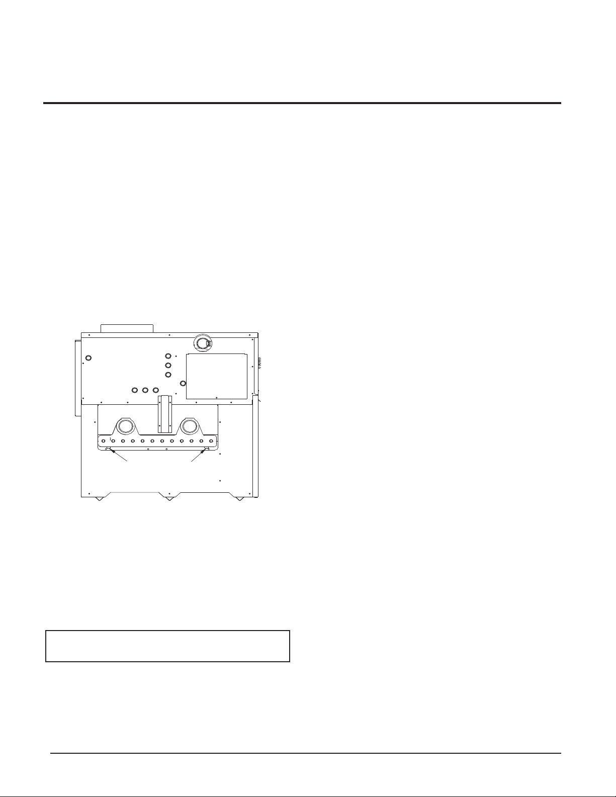
4. Drain the unit completely. Remove one threaded plug or
bulbwell from the inlet side of the front header and one
from the outlet side of the front header on the heat
exchanger. Blow all water out of the heat exchanger (see
FIG. 3).
5. Drain pump and piping.
FIG. 3 Draining Unit
Freeze Protection for a Heating
Boiler System (if required)
1. Use only properly diluted inhibited glycol antifreeze
designed for hydronic systems. Inhibited propylene glycol
is recommended for systems where incidental contact with
drinking water is possible.
2. A solution of 50% antifreeze will provide maximum
protection of approximately -30°F (-34°C).
3. Follow the instructions from the antifreeze manufacturer.
Quantity of antifreeze required based on total system
volume including expansion tank volume.
4. Glycol is denser than water and changes the viscosity of
the system. The addition of glycol will decrease heat
transfer and increase frictional loss in the boiler and related
piping. A larger pump with more capacity (15% to 25%
more) may be required to maintain desired flow rates and
prevent a noise problem in a glycol system.
5. Local codes may require a back flow preventer or actual
disconnect from city water supply when antifreeze is
added to the system.
COMBUSTION AND VENTILATION
AIR
Provisions for combustion and ventilation air must be in
accordance with Section 5.3, Air for Combustion and
Ventilation, of the latest edition of the National Fuel Gas Code,
ANSI Z223.1, in Canada, the latest edition of CAN/CGAB149 Installation Code for Gas Burning Appliances and
Equipment, or applicable provisions of the local building
codes.
Provide properly-sized openings to the equipment room to
assure adequate combustion air and proper ventilation when
the unit is installed with conventional venting or sidewall
venting.
Combustion Air Filter
This unit has a standard air filter located at the combustion air
inlet. This filter helps ensure clean air is used for the
combustion process. Check this filter every month and replace
when it becomes dirty. The filter size on the 399,999 - 750,000
units is 12" x 12" x 1" (30.5cm x 30.5cm x 2.5cm) and 16" x
16" x 1 (40.6cm x 40.6cm x 2.5 cm) on the 990,000 -
2,070,000 units. You can find these commercially available
filters at any home center or HVAC supply store.
For convenience and flexibility, you can direct the combustion
air inlet from either the back or right side of the unit. To
arrange the combustion air inlet for side entry, follow the steps
below:
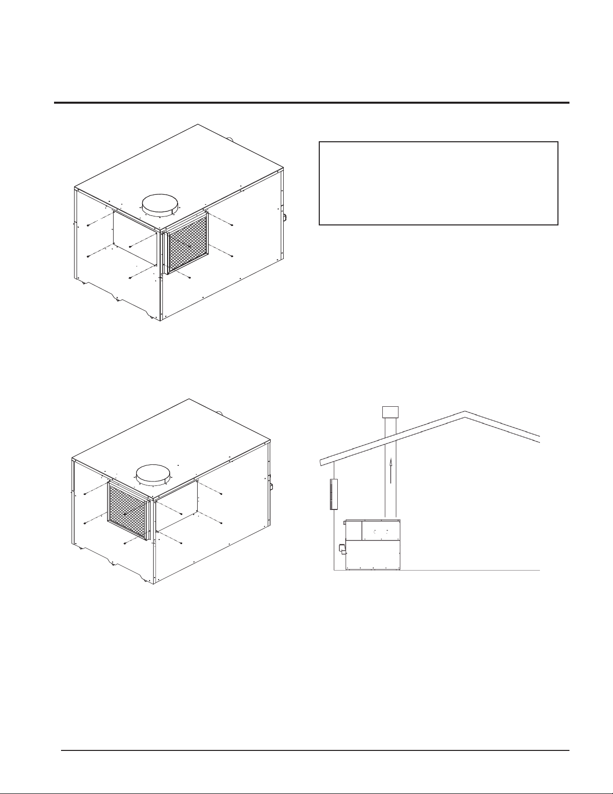
1. Remove the metal panel from the unit’s side wall (see
FIG. 4).
2. Remove screws from the air filter/bracket assembly.
3. Move the filter/bracket assembly from the rear of unit to
the side opening (see FIG. 5).
4. Attach filter/bracket assembly to the unit’s side using the
pre-drilled screw holes.
5. Attach the metal panel to the rear combustion air opening
to seal it off.
WARNING: Do not use undiluted or
automotive type antifreeze.
DRAIN PLUG
DRAIN PLUG
Page 9
Installation and
Service Manual
9
FIG. 4 Metal Panel Covering Side Combustion Air Inlet
FIG. 5 Moving Air Filter/Bracket Assembly from Rear of
Unit to Side
Combustion Air Options
This unit has four combustion air options.
1. Outside Combustion Air, No Ducts
You can direct outside combustion air to this unit using either
one or two permanent openings.
One Opening
The opening must have a minimum free area of one square
inch per 3000 Btu input (7cm
2
per kW). You must locate this
opening within 12" (30cm) of the top of the enclosure.
FIG. 6 Outside Combustion Air - Single Opening
Two Openings
The combustion air opening must have a minimum free area of
one square inch per 4000 Btu/hr input (5.5cm
2
per kW). You
must locate this opening within 12" (30cm) of the bottom of
the enclosure.
The ventilation air opening must have a minimum free area of
one square inch per 4000 Btu/hr input (5.5cm2per kW). You
must locate this opening within 12" (30cm) of the top of the
enclosure.
CAUTION: Under no circumstances
should the mechanical room ever be under a
negative pressure. Particular care should be
taken where exhaust fans, attic fans, clothes
dryers, compressors, air handling units, etc.,
may take away air from the unit.
Page 10
Hydronic Heating Boilers and
Domestic Water Heaters
10
INSTALLATION
Continued
FIG. 7 Outside Combustion Air - Two Openings
2. Outside Combustion Air, Using Ducts
You can direct outside combustion air to this unit using two air
ducts to deliver the air to the boiler room.
Each of the two openings must have a minimum free area of
one square inch per 2000 Btu input (11cm
2
per kW).
FIG. 8 Outside Combustion Air Through Ducts
3. Outside Combustion Air - Using Direct Venting
With this option, you can connect combustion air vent piping
directly to the unit. See the information under Direct Venting
starting on page 22 for specific information regarding this
option.
4. Combustion Air from Interior Space
You can direct combustion air to this unit using air from an
adjoining interior space. You must provide two openings from
the boiler room to the adjoining room.
Each of the two openings must have a net free area of one
square inch per 1000 Btu input (22cm
2
per kW), but not less
than 100 square inches (645cm2).
FIG. 9 Combustion Air from Interior Space
All dimensions are based on net free area in square inches.
Metal louvers or screens reduce the free area of a combustion
air opening a minimum of approximately 25%. Check with
louver manufacturers for exact net free area of louvers. Where
two openings are provided, one must be within 12" (30 cm) of
the ceiling and one must be within 12" (30 cm) of the floor of
the mechanical room. Each opening must have a minimum net
free area as specified in TABLE–C, page 14. Single openings
shall be installed within 12" (30 cm) of the ceiling.
The combustion air supply must be completely free of any
flammable vapors that may ignite or chemical fumes which
may be corrosive to the unit. Common corrosive chemical
fumes which must be avoided are fluorocarbons and other
halogenated compounds, most commonly present as
refrigerants or solvents, such as Freon, trichlorethylene,
perchlorethylene, chlorine, etc. These chemicals, when burned
form acids which quickly attack the heat exchanger finned
tubes, headers, flue collectors, and the vent system. The result
is improper combustion and a non-warrantable, premature unit
failure.
Page 11

Installation and
Service Manual
11
Exhaust Fans
Any fan or equipment which exhausts air from the boiler room
may deplete the combustion air supply and/or cause a down
draft in the venting system. Spillage of flue products from the
venting system into an occupied living space can cause a very
hazardous condition that must be immediately corrected. If a
fan is used to supply combustion air to the boiler room, the
installer must make sure that it does not cause drafts which
could lead to nuisance operational problems with the boiler.
Vertical DirectAire™ and Horizontal DirectAire™ venting
systems have specific requirements for combustion air ducts
from the outside which are directly connected to the unit. See
the requirements for combustion air duct in the venting
section.
VENTING
General Information
You must supply adequate combustion and ventilation air to
this unit. You must provide minimum clearances for the vent
terminal from adjacent buildings, windows that open, and
building openings. Follow all requirements set forth in the
latest edition of the National Fuel Gas Code, ANSI Z223.1, in
Canada, the latest edition of CAN/CGA Standard B149
Installation Code for Gas Burning Appliances and Equipment
or applicable local building codes. Vent installations for
connection to gas vents or chimneys must be in accordance
with Part 7, “Venting of Equipment” of the above-mentioned
standards.
Venting Support
Support horizontal portions of the venting system to prevent
sagging. Provide an upward slope of at least 1/4 inch per foot
(21mm/m) on all horizontal runs from the unit to the vertical
flue run or to the vent terminal on sidewall venting
installations.
Do not use an existing chimney as a raceway if another
appliance or fireplace is vented through the chimney. The
weight of the venting system must not rest on the unit. Provide
adequate support of the venting system. Follow all local and
applicable codes. Secure and seal all vent connections. Follow
the installation instructions from the vent material
manufacturer.
Vertical Vent Termination Clearances
and Location
The vent terminal should be vertical and exhaust outside the
building at least 2 feet (0.61m) above the highest point of the
roof within a 10 foot (3.05m) radius of the termination.
The vertical termination must be a minimum of 3 feet (0.91m)
above the point of exit.
A vertical termination less than 10 feet (3.05m) from a parapet
wall must be a minimum of 2 feet (0.61m) higher than the
parapet wall.
You must locate the air inlet termination elbow at least 12"
(30cm) above the roof or above normal snow levels.
Keep the vent cap clear of snow, ice, leaves, and debris to
avoid blocking the flue.
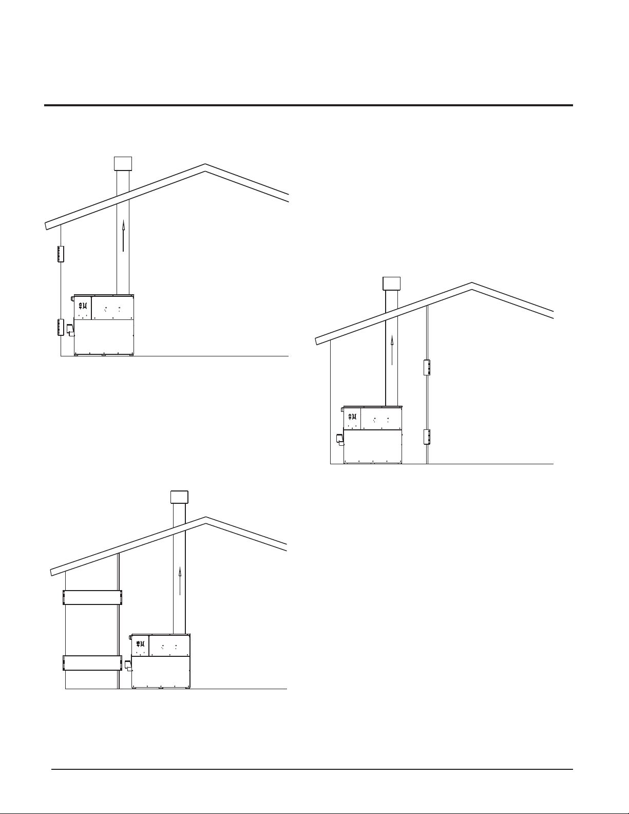
FIG. 10 Vent Termination from Peaked Roof - 10’ or Less
From Ridge
10' OR LESS
RIDGE
CHIMNEY
3' MIN.
2' MIN.
IMPORTANT: Examine the venting system at
least once each year. Check all joints and
vent pipe connections for tightness. Also
check for corrosion or deterioration. If you
find any problems, correct them at once.
IMPORTANT: Vent terminations are not shown
in Figures 10, 11, 12, and 13. Make sure all
vertical vents are installed with vent
terminations recommended by the vent
manufacturer.
Page 12

Hydronic Heating Boilers and
Domestic Water Heaters
12
INSTALLATION
Continued
FIG. 11 Vent Termination from Peaked Roof More Than 10’
From Ridge
FIG. 12 Vent Termination from Flat Roof 10’ or Less from
Parapet Wall
FIG. 13 Vent Termination from Flat Roof More Than 10’
from Parapet Wall
Sidewall Vent Termination Clearances and
Location
Locate the bottom of the vent terminal at least 12 inches (30cm)
above grade and above normal snow levels. Locate the bottom of
the vent terminal at least 7 feet (2.13m) above grade when
located adjacent to public walkways. Do not terminate directly
above a public walkway.
Do not terminate the venting system in a window well, stairwell,
alcove, courtyard, or other recessed area. Do not terminate the
venting system below grade.
Locate vent termination at least 3 feet (0.91m) from an inside
corner of an L-shaped structure.
Provide a minimum clearance of 4 feet (1.2m) horizontally from
electric meters, gas meters, regulators, and relief equipment.
Never locate vent cap above or below electric meters, gas meters,
regulators, and relief equipment unless a 4 foot (1.2m) horizontal
clearance is maintained.
Terminate the venting system at least 3 feet (0.9m) above any
forced air inlet within 10 feet (3.05m).
Terminate the venting system at least 4 feet (1.2m) below, 4 feet
(1.2m) beside, or 1 foot (30cm) above any door, window, or
gravity air inlet into any building.
Locate vent termination at least 8 feet (2.4m) horizontally from
any combustion air intake located above the sidewall termination
cap.
TAB
L
CAUTION: Units which are shut down or
will not operate may experience freezing due to
convective air flow in flue pipe, through the air
inlet, or from negative pressure in the
mechanical room. In cold climates, operate
pump continuously to help prevent freezing of
boiler water. Provide proper freeze protection.
See Freeze Protection, page 7.
MORE THAN 10'
RIDGE
2' MIN.
CHIMNEY
10'
3' MIN.
10' OR LESS
2' MIN.
2' MIN.
3' MIN.
CHIMNEY
WALL OR
PARAPET
CHIMNEY
10' OR LESS
3' MIN.
NOTE: NO HEIGHT
ABOVE PARAPET
REQUIRED WHEN
DISTANCE FROM
WALLS OR PARAPET
IS MORE THAN 10'.
WALL OR
PARAPET
CHIMNEY
Page 13
Installation and
Service Manual
13
Input Flue Air Inlet
Btu/hr Size Size*
399,999 6" 6"
500,000 6" 6"
650,000 8" 8"
750,000 8" 8"
990,000 10" 10"
1,260,000 12" 12"
1,440,000 12" 12"
1,800,000 14" 12"
2,070,000 14" 12"
* Minimum diameter for air inlet pipe. Installer may increase diameter one pipe
size for ease of installation, if needed.
Combustion Air Inlet Piping
The sidewall or vertical rooftop DirectAire™ combustion air
supply system has specific vent material and installation
requirements. The air inlet pipe connects directly to the unit to
supply combustion air. In most installations, the combustion air
inlet pipe will be a dedicated system with one air inlet pipe per
unit. You can combine multiple air inlets if the guidelines in
Combined Air Inlet Points, page 15 are followed. The air inlet
pipe will be connected to a combustion air inlet cap as specified
in this section.
For normal installations, this system uses a single-wall pipe to
supply combustion air from outdoors directly to the unit.
In cold climates, use a Type-B double-wall vent pipe or an
insulated single-wall pipe for combustion air. This will help
prevent moisture in the cool incoming air from condensing and
leaking from the inlet pipe.
Length of Air Inlet Pipe
The installed length of air inlet pipe from the unit to the outside air
inlet cap must not exceed 50 equivalent feet (15.2m). Subtract
5 feet (1.5m) of equivalent length for each 90° elbow. Subtract
2.5 feet (0.7m) of equivalent length for each 45° elbow.
Do not exceed the limits for the combustion air inlet piping
lengths.
Sidewall Air Inlet
The sidewall air inlet cap is supplied in the Horizontal
DirectAire™ Vent Kit. Order the kit from the appliance
manufacturer. This sidewall cap supplies combustion air for a
single unit only. See TABLE–D, page 19, for kit numbers.
Locate the unit as close as possible to the sidewall where you will
install the combustion air supply system.
FIG. 14 Sidewall Combustion Air Inlet
TABLE - B
Flue and Air Inlet Pipe Sizes
WARNING: Locate and install the
combustion air inlet cap correctly. Failure to
do so can allow the discharge of flue products
to be drawn into the combustion process.
This can result in incomplete combustion and
potentially hazardous levels of carbon
monoxide in the flue products. This will cause
operational problems and the spillage of flue
products. Spillage of flue products can cause
personal injury or death due to carbon
monoxide poisoning.
Page 14

Hydronic Heating Boilers and
Domestic Water Heaters
14
INSTALLATION
Continued
FIG. 15 Air Inlet Cap for Sidewall Termination
To prevent recirculation of flue products from an adjacent vent
cap into the combustion air inlet, follow all applicable
clearance requirements in the latest edition of the National
Fuel Gas Code and/or CAN/CGA-B149 Installation Code and
instructions in the Installation and Service Manual.
You must install the combustion air inlet cap at least one foot
(0.30m) above ground level and above normal snow levels.
The point of termination for the combustion air inlet cap must
be at least 3 feet (0.91m) below the point of flue gas
termination (powered vent cap) if it is located within 10 feet
(3.05m) of the flue outlet from the powered vent cap. Make
sure to properly install the air inlet cap assembly on the air
inlet pipe.
You must install the combustion air inlet cap and the powered
vent cap on the same wall and in the same pressure zone.
Do not install the combustion air inlet cap closer than 10 feet
(3.05m) from an inside corner of an L-shaped structure.
Vertical Rooftop Air Inlet
Use the vertical air inlet terminations available from the
appliance manufacturer, recommended and/or supplied by the
vent manufacturer, or use two 90° elbows as described on
page 24.
FIG. 16 Roof Top Combustion Air Inlet
Clearances
You must locate the air inlet termination elbow at least 12"
(30cm) above the roof or above normal snow levels.
12"
3'
TABLE–C
Minimum Recommended Combustion Air Supply To Boiler Room
Combustion Air Source
Boiler Input Outside Air*/2 Openings Outside Air*/1 Opening Inside Air/2 Openings
399,999 100 in2(745 cm2) 133 in2(858 cm2) 400 in2(2581 cm2)
500,000 125 in
2
(806 cm2) 167 in2(1077 cm2) 500 in2(3226 cm2)
650,000 163 in
2
(1052 cm2) 217 in2(1400 cm2) 650 in2(4194 cm2)
750,000 188 in
2
(1213 cm2) 250 in2(1613 cm2) 750 in2(4839 cm2)
990,000 248 in2(1,600cm2) 330 in2(2,129 cm2) 990 in2(6,388 cm2)
1,260,000 315 in
2
(2,032cm2) 420 in2(2,710 cm2) 1260 in2(8,130 cm2)
1,440,000 360 in2(2,323cm2) 480 in2(3,097 cm2) 1440 in2(9,291 cm2)
1,800,000 450 in2(2,903cm2) 600 in2(3,871 cm2) 1800 in2(11,614 cm2)
2,070,000 518 in2(3,342cm2) 690 in2(4,452 cm2) 2070 in2(13,356 cm2)
*Outside air openings shall directly communicate with the outdoors. When combustion air is drawn from the outside through a duct, the net free area of each of the two openings
must have twice (2 times) the free area required for Outside Air/2 Openings. The above requirements are for the boiler only, additional gas fired units in the boiler room will require
an increase in the net free area to supply adequate combustion air for all units. Combustion air requirements are based on the latest edition of the National Fuel Gas Code, ANSI
Z223.1, in Canada refer to CAN/CGA-B149 Installation Code. Check all local code requirements for combustion air.
Page 15

Installation and
Service Manual
15
If the air inlet cap is within a 10-foot (3.05m) radius of the flue
outlet, the point of termination for the combustion air inlet cap
must be at least 3 feet (0.91m) below the point of flue gas
termination (vent cap).
Do not install the combustion air inlet cap closer than 10 feet
(3.05m) from an inside corner of an L-shaped structure.
Combined Air Inlet Points
The air inlet pipes from multiple boilers can be combined to a
single common connection if the common air inlet pipe has a
cross sectional area equal to or larger than the total area of all
air inlet pipes connected to the common air inlet pipe.
Example: Two 10" air inlet pipes (78.5 in
2
area each) have a
total area of 157 in
2
and will require a 15" (176.7 in2area)
common air inlet pipe.
The air inlet point for multiple boiler air inlets must be
provided with an exterior opening which has a free area equal
to or greater than the total area of all air inlet pipes connected
to the common air inlet. This exterior opening for combustion
air must connect directly to the outdoors. The total length of
the combined air inlet pipe must not exceed a maximum of 50
(15.2m) equivalent feet. Subtract 5 feet (1.5m) for each 90°
elbow in the air inlet pipe. You must deduct the restriction in
area provided by any screens, grills or louvers installed in the
common air inlet point. These are common on the sidewall air
inlet openings. Screens, grills or louvers installed in the
common air inlet can reduce the free area of the opening from
25% to 75% based on the materials used.
Vent System Options
This unit has six venting options.
1. Conventional Negative Draft Venting
This option uses a vertical rooftop flue termination.
Combustion air is supplied from the mechanical room. See
column 2 for detailed information.
2. Vertical DirectAire™ Venting
This option uses a vertical conventional vent for flue products.
Combustion air is supplied by a pipe from the sidewall or
rooftop. See page 17 for venting details.
3. Sidewall Venting
This option uses a powered vent assembly to exhaust the flue
products out a sidewall vent termination. Combustion air is
supplied from the mechanical room. See page 19 for venting
details.
4. Horizontal DirectAire™ Venting
This option uses a powered vent assembly to exhaust the flue
products out a sidewall. Combustion air is supplied by a pipe
from the sidewall. See page 21 for venting details.
5. Direct Venting
This option uses a sealed AL29-4C flue and a separate
combustion air pipe to the outdoors. This system terminates
both the flue and combustion air inlet in the same pressure
zone. The flue outlet and combustion air intake may terminate
at either a sidewall (horizontal) or the rooftop (vertical). See
page 22 for venting details.
6. Outdoor Installation Venting
This option uses the installation of a special air inlet/vent cap
on top of the unit. See page 26 for venting details.
All units are shipped from the factory equipped for
conventional negative draft venting. All other optional vent
systems require the installation of specific vent kits and
venting materials. The following is a detailed explanation of
the installation requirements for each venting system,
components used and part numbers of vent kits for each model.
Barometric Damper Location
Any venting system option that requires a barometric damper
must adhere to the following directions for optimum
performance.
The preferred location for the barometric damper is in a tee or
collar installed in the vertical pipe rising from the unit’s flue
outlet. The barometric damper MUST NOT be installed in a bull
head tee installed on the unit’s flue outlet. The tee or collar
containing the barometric damper should be approximately three
feet vertically above the connection to the unit’s flue outlet. This
location ensures that any positive velocity pressure from the
unit’s internal combustion fan is dissipated and the flue products
are rising due to buoyancy generated from the temperature of the
flue products. Adjust the weights on the damper to ensure that
draft is maintained within the specified range.
Page 16

Hydronic Heating Boilers and
Domestic Water Heaters
16
INSTALLATION
Continued
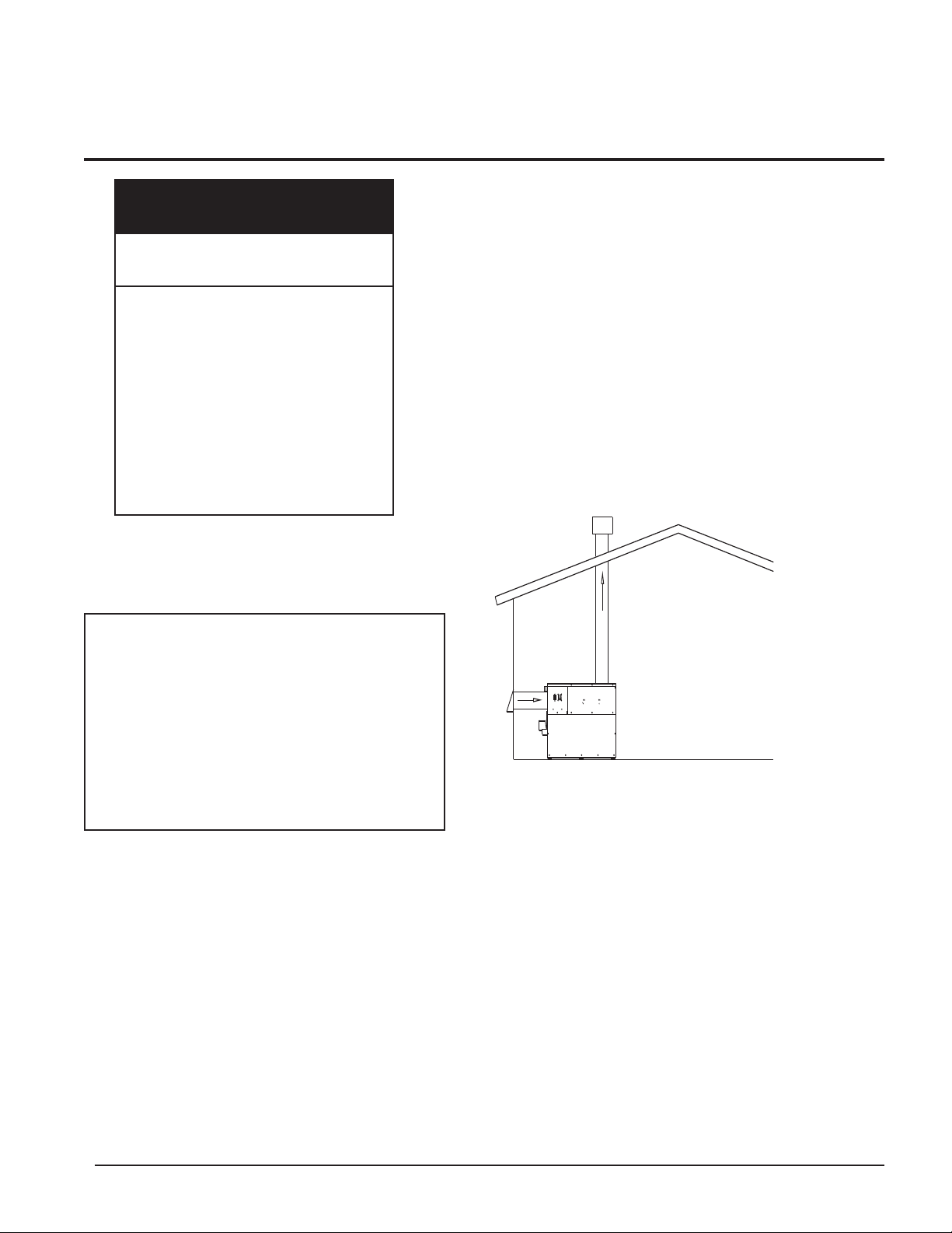
1. Conventional Negative Draft
Venting
FIG. 17 Conventional Negative Draft Vertical Venting with
Combustion Air Louvers
This option uses Type-B double-wall flue outlet piping. The
blower brings in combustion air. The buoyancy of the heated flue
products cause them to rise up through the flue pipe. The flue
outlet terminates at the rooftop.
Negative Draft
The negative draft in a conventional vent installation must be
within the range of 0.02 to 0.08 inches w.c. to ensure proper
operation. Make all draft readings while the unit is in stable
operation (approximately 2 to 5 minutes).
Connect the flue vent directly to the flue outlet opening on the top
of the unit. No additional draft diverter or barometric damper is
needed on single unit installations with a dedicated stack and a
negative draft within the specified range of 0.02 to 0.08 inches
w.c. If the draft in a dedicated stack for a single unit installation
exceeds the maximum specified draft, you must install a
barometric damper to control draft. Multiple unit installations
with combined venting or common venting with other Category I
negative draft appliances require each boiler to have a barometric
damper installed to regulate draft within the proper range.
Do not connect vent connectors serving appliances vented by
natural draft (negative draft) to any portion of a mechanical draft
system operating under positive pressure. Connecting to a positive
pressure stack may cause flue products to be discharged into the
living space causing serious health injury.
Flue Outlet Piping
With this venting option, you must use Type-B double-wall (or
equivalent) vent materials. Vent materials must be listed by a
nationally-recognized test agency for use as vent materials. Make
the connections from the unit vent to the outside stack as direct as
possible with no reduction in diameter. Use the National Fuel Gas
Code venting tables for double-wall vent to properly size all vent
connectors and stacks. Follow the vent manufacturer’s
instructions when installing Type-B vents and accessories, such as
firestop spacers, vent connectors, thimbles, caps, etc.
Provide adequate clearance to combustibles for the vent connector
and firestop.
When planning the venting system, avoid possible contact with
plumbing or electrical wiring inside walls, ceilings, and floors.
Locate the unit as close as possible to a chimney or gas vent.
Avoid long horizontal runs of the vent pipe, 90° elbows,
reductions and restrictions.
No additional draft diverter or barometric damper is required on
single unit installations with a dedicated stack and a negative draft
maintained between 0.02 to 0.08 inches w.c.
Common Venting Systems
You can combine the flue with the vent from any other negative
draft, Category I appliance. Using common venting for multiple
negative draft appliances requires you to install a barometric
damper with each unit. This will regulate draft within the proper
range. You must size the common vent and connectors from
multiple units per the venting tables for Type-B double-wall vents
in the latest edition of the National Fuel Gas Code, ANSI Z223.1
and/or CAN/CGA-B149 Installation Code.
Common venting systems may be too large when an existing unit
is removed.
At the time of removal of an existing appliance, the following
steps shall be followed with each appliance remaining connected
to the common venting system placed in operation, while other
appliances remaining connected to the common venting system
are not in operation.
1. Seal any unused opening in the common venting system.
2. Visually inspect the venting system for proper size and
horizontal pitch. Make sure there is no blockage or restriction,
leakage, corrosion and other unsafe conditions.
IMPORTANT: Before installing a venting
system, follow all venting clearances and
requirements found in the Venting, General
Information section, page 11.
Page 17

Installation and
Service Manual
17
3. If possible, close all building doors and windows. Close all
doors between the space in which the appliances remaining
connected to the common venting system are located and
other building spaces.
4. Turn on clothes dryers and any other appliances not
connected to the common venting system. Turn on any
exhaust fans, such as range hoods and bathroom exhausts,
so they will operate at maximum speed. Do not operate a
summer exhaust fan.
5. Close fireplace dampers.
6. Place in operation the unit being inspected. Follow the
lighting instructions. Adjust thermostat so unit will operate
continuously.
7. Test for spillage at the draft hood/relief opening after
5 minutes of main burner operation. Use the flame of a
match or candle, or smoke from a cigarette, cigar or pipe.
8. After making sure that each appliance remaining
connected to the common venting system properly vents
when tested as above, return doors, windows, exhaust fans,
fireplace dampers and other gas burning appliances to their
previous conditions of use.
9. Correct any improper operation of the common venting
system so that the installation conforms to the latest edition
of the National Fuel Gas Code, ANSI Z223.1, in Canada,
the latest edition of CAN/CGA-B149 Installation Code for
Gas Burning Appliances and Equipment. When resizing
any portion of the common venting system, resize to
approach the minimum size as determined using the
appropriate tables of the latest edition of the National Fuel
Gas Code, ANSI Z223.1, in Canada, the latest edition of
CAN/CGA-B149 Installation Code for Gas Burning
Appliances and Equipment.
Masonry Chimney Installations
A masonry chimney must be properly sized for the installation
of a high efficiency gas-fired appliance. Venting of a high
efficiency appliance into a cold or oversized masonry chimney
can result in operational and safety problems. Exterior
masonry chimneys, with one or more sides exposed to cold
outdoor temperatures, are more likely to have venting
problems. The temperature of the flue products from a high
efficiency appliance may not be able to sufficiently heat the
masonry structure of the chimney to generate proper draft. This
will result in condensing of flue products, damage to the
masonry flue/tile, insufficient draft and possible spillage of
flue products into an occupied living space. Carefully inspect
all chimney systems before installation.
Inspection of a Masonry Chimney
A masonry chimney must be carefully inspected to determine its
suitability for the venting of flue products. A clay-tile-lined
chimney must be structurally sound, straight and free of
misaligned tile, gaps between liner sections, missing sections of
liner or any signs of condensate drainage at the breaching or clean
out. If there is any doubt about the condition of a masonry
chimney, it must be relined with a properly-sized and approved
chimney liner system. An unlined masonry chimney must not be
used to vent flue products from this high-efficiency unit. An
unlined chimney must be relined with an approved chimney
liner system when a new appliance is being attached to it.
Metallic liner systems (Type-B double-wall or flexible or rigid
metallic liners) are recommended. Consult with local code
officials to determine code requirements or the advisability of
using or relining a masonry chimney.
Vertical Vent Termination Clearances and Location
Follow all vertical venting termination information for
clearances and location under Vertical Vent Termination
Clearances and Location, page 11.
2. Vertical DirectAire™ Venting
The Vertical DirectAire™ vent system is the same as the
Conventional Negative Draft vent system, except it pulls
combustion air from the outdoors through a vertical air inlet.
Follow all requirements in 1. Conventional Negative Draft
Venting, page 16.
IMPORTANT: Before installing the venting
system, follow all venting clearances and and
requirements found in the Venting, General
Information section, page 11.
WARNING: Do not vent this unit into a
masonry chimney without a sealed stainless
steel liner system. Any breaks, leaks, or damage
to the masonry flue/tile will allow the positivepressure flue products to leak from the chimney
and into occupied living spaces. This could
cause serious injury or death due to carbon
monoxide poisoning and other harmful flue
products.
IMPORTANT: Check with local code officials to
determine code requirements or the advisability
of using a masonry chimney with a sealed
corrosion-resistant liner system.
Page 18

Hydronic Heating Boilers and
Domestic Water Heaters
18
INSTALLATION
Continued
The Vertical DirectAire™ vent system requires you to install
two vent pipes directly to the unit; one vertical pipe with a
rooftop termination for the flue products and one pipe for
combustion air. For this venting option, you must purchase the
DV box adapter from the appliance manufacturer. The DV box
attaches to the air inlet of the unit. The pipe for combustion air
attaches to the DV box.
You can terminate the combustion air pipe either horizontally
with a sidewall air inlet or vertically with a rooftop air inlet.
The installed length of air inlet pipe from the unit to the outside air
inlet cap must not exceed 50 equivalent feet (15.2m).
FIG. 18 Vertical DirectAire Installation with Sidewall
Combustion Air Inlet
FIG. 19 Air Inlet Cap for Sidewall Termination
FIG. 20 Vertical DirectAire Installation with Roof Top
Combustion Air Inlet
Vent Kits
For single unit installations with sidewall air inlet, (see
FIG. 18) you must order the sidewall air inlet kit from the
appliance manufacturer. The part number for each SVK kit is
listed by unit size in TABLE–D.
For single unit installations with rooftop air inlet (see FIG. 20),
you must order the rooftop air inlet kit from the appliance
manufacturer. The part number for each VDK kit is listed by
unit size in TABLE-D. Purchase the flue pipe, rooftop flue
termination, and air inlet pipe locally.
There is no vent kit for combined air supply systems for
multiple units. Make sure the air inlet cap is properly sized.
You must purchase this cap locally.
Venting of Flue Products
For venting flue products vertically to the outdoors, follow all
requirements in the installation instructions for conventional
venting in this manual.
Follow all clearance requirements in Vertical Vent Termination
Clearances and Location, page 11.
A barometric damper is not required in the flue on Vertical
DirectAire™ installations if the draft is within the negative
0.02 to 0.08 inches w.c. required for proper operation. If the
draft exceeds this range, install a barometric damper.
™
WARNING: Only use a sidewall air inlet
cap supplied by the appliance
manufacturer or a rooftop air inlet cap
supplied by the vent manufacturer. Using
any other air inlet cap for single unit
installations or using a common air inlet
cap for multiple units with insufficient free
area and/or protections from wind and
weather may result in operational problems
and the spillage of flue products. Spillage
of flue products can cause personal injury
or death due to carbon monoxide
poisoning.
12"
3'
Page 19

Installation and
Service Manual
19
*The SVK kits include a DV box adapter and sidewall air inlet cap. The VDK kits include
a DV box adapter and a rooftop air inlet cap.
3. Sidewall Venting
This option uses a powered vent assembly which pulls the flue
products out of the stack. This fan generates a negative draft at
the unit. Combustion air is drawn from the mechanical room
(see Combustion and Ventilation Air, page 8).
FIG. 21 Sidewall Venting Installation with an Induced
Draft Fan and Sidewall Vent Cap
Sidewall Fan
The sidewall fan can be mounted on the inside/outside
(depending upon model) with a sidewall vent hood installed on
the exterior wall. The sidewall fan and accessories are included
in a venting kit provided by the appliance manufacturer. See
TABLE–E for kit numbers.
The venting kit includes the sidewall fan, vent hood, tapered
vent adapter, barometric damper, proving switch and all
necessary relays to interlock with the heaters control system.
The tapered vent adapter reduces the vent size at the inlet to the
fan. There should be no reduction in vent diameter from the
unit’s flue outlet to the sidewall fan. The barometric damper
must be installed on the flue and adjusted to supply a negative
draft within the range of 0.04 to 0.08 inches w.c. while unit is
operating.
Flue Outlet Piping
With this venting option, you must use Type-B double-wall (or
equivalent) vent materials. Vent materials must be listed by a
nationally-recognized test agency for use as vent materials.
Make the connections from the unit vent to the sidewall
fan/cap as direct as possible with no reduction in diameter. Use
the National Fuel Gas Code venting tables for double-wall vent
to properly size all vent connectors and stacks. Follow the vent
manufacturer’s instructions when installing Type-B vents and
accessories, such as firestop spacers, vent connectors,
thimbles, caps, etc.
When planning the venting system, avoid possible contact with
plumbing or electrical wiring inside walls.
The maximum installed length of sidewall vent pipe with an
induced draft fan must not exceed 100 feet (30.5m). Subtract
5 feet (1.5m) for each 90° elbow. Subtract 2.5 feet (0.7m) for
each 45° elbow.
Sidewall Venting Termination
The sidewall vent cap must be installed on an exterior sidewall.
The sidewall fan/powered sidewall vent cap and accessories
are included in a venting kit which is furnished by the
appliance manufacturer in accordance with CSA International
requirements. This venting kit includes the powered sidewall
fan/cap, proving switch and all necessary relays to interlock
with the heaters control system.
The sidewall fan/powered vent cap must be interlocked with
the units control system to start the fan on a call for heat and
prove fan operation before the boiler fires. Plug-in and
terminal strip connections are provided on the unit for easy
connection of the factory supplied vent kit and control package
for the sidewall vent fan. See the installation instructions
provided with the vent kit.
Sidewall Venting Without Fan
For 399,999 - 750,000 Btu/hr models approved for sidewall
venting without an external power vent fan, you must install
specific vent kits and venting materials.
IMPORTANT: Before installing venting
system, follow all venting clearances and
requirements found in the Venting, General
Information section, page 11.
Input Horizontal Vertical
Btu/hr Kit* Kit*
399,999 SVK3047 VDK3026
500,000 SVK3047 VDK3026
650,000 SVK3048 VDK3027
750,000 SVK3048 VDK3027
990,000 SVK3040 VDK3023
1,260,000 SVK3041 VDK3024
1,440,000 SVK3041 VDK3024
1,800,000 SVK3041 VDK3024
2,070,000 SVK3041 VDK3024
TABLE-D
DirectAire™ Kits
Page 20

Hydronic Heating Boilers and
Domestic Water Heaters
20
INSTALLATION
Continued
The following is a detailed explanation of Sidewall Venting
Without an External Power Vent Fan installation requirements.
Flue Outlet Piping
Venting Guidelines
If using this venting option, a sealed AL29-4C venting system
for flue products is required on all models of this appliance.
This venting system operates with a positive pressure in the
vent. The internal combustion air blowers generate this
positive pressure which operates the combustion process and
also exhausts the flue products from the building.
This vent system has specific vent material and installation
requirements. Only use listed sealed AL29-4C vent system
materials. Follow all installation requirements. See TABLE–B,
page 13 for proper pipe size for your unit. A list of sealed
AL29-4C flue pipe manufacturers is located on page 24.
Seal all vent joints and seams gas-tight.
Drain Tee Installation
A drain tee must be installed in the vent pipe to collect and
dispose of any condensate that may occur in the vent system.
The drain tee must be installed as the first fitting after the
horizontal ell on the top of the unit. Plastic drain tubing, sized
per the vent manufacturer’s instructions, shall be provided as a
drain line from the tee. The drain tubing must have a trap
provided by a 3" (7.6cm) diameter circular trap loop in the
drain tubing. Prime the trap loop by pouring a small quantity
of water into the drain hose before assembly to the vent. Secure
the trap loop in position with nylon wire ties. Use caution not
to collapse or restrict the condensate drain line with the nylon
wire ties. The condensate drain must be routed to a suitable
drain for disposal of condensate that may occur in the direct
vent system. Refer to the condensate drain installation
instructions as supplied by the manufacturer of the vent
material.
FIG. 22 Sidewall Vent
Connect the flue vent directly to the flue outlet opening on the
top of unit. Make the connections from the unit vent to the
outside stack as direct as possible with no reduction in
diameter. Provide adequate clearance to combustibles for the
vent connector and firestop. Follow the vent manufacturer’s
instructions when installing sealed AL29-4C vents and
accessories, such as firestop spacers, vent connectors,
thimbles, caps, etc.
Provide adequate clearance to combustibles for the vent
connector and firestop.
When planning the venting system, avoid possible contact with
plumbing or electrical wiring inside walls, ceilings, and floors.
Locate the unit as close as possible to chimney or gas vent.
When a vent system is disconnected for any reason, the flue
must be reassembled and resealed according to the vent
manufacturer’s instructions.
The installed length of flue from the unit to the outside point
of termination must not exceed 50 equivalent feet (15.2m).
Subtract 5 feet (1.5m) of equivalent length for each 90° elbow.
Subtract 2.5 feet (0.7m) of equivalent length for each 45°
elbow.
WARNING: Do not combine the flue
from this unit with the vent from any other
appliance. Do not combine flues from
multiple appliances into a common vent.
The flue from this unit must be a dedicated
stack.
Page 21

Installation and
Service Manual
21
Masonry Chimney Installation
A masonry chimney must be properly sized for the installation
of a high efficiency gas-fired appliance. Venting of a high
efficiency appliance into a cold or oversized masonry chimney
can result in operational and safety problems. Exterior
masonry chimneys, with one or more sides exposed to cold
outdoor temperatures, are more likely to have venting
problems. The temperature of the flue products from a high
efficiency appliance may not be able to sufficiently heat the
masonry structure of the chimney to generate proper draft. This
will result in condensing of flue products, damage to the
masonry flue/tile, insufficient draft and possible spillage of
flue products into an occupied living space. Carefully inspect
all chimney systems before installation.
Sidewall Vent Termination Clearances and
Location
Follow all sidewall venting termination information for
clearances and location under Sidewall Vent Termination
Clearances and Location, page 12.
Input Kit* Max. Vent Vent Max. Vent
Btu/hr (w/Power Length Termination Only Length
Fan Assy.)
(399,999 - 750,000 Btu/hr)
399,999 SVK3006 100 ft. SVK3043 50 ft.
500,000 SVK3006 100 ft. SVK3043 50 ft.
650,000 SVK3008 100 ft. SVK3044 50 ft.
750,000 SVK3008 100 ft. SVK3044 50 ft.
990,000 SVK3009 100 ft. N/A N/A
1,260,000 SVK3010 100 ft. N/A N/A
1,440,000 SVK3010 100 ft. N/A N/A
1,800,000 SVK3012 100 ft N/A N/A
2,070,000 SVK3012 100 ft. N/A N/A
*These kits include a sidewall venter assembly, vent termination, and barometric damper.
4. Horizontal DirectAire™ Venting
The Horizontal DirectAire™ vent system is the same as the
Sidewall Venting system, except it pulls combustion air from the
outdoors through a sidewall air inlet. Follow all requirements in
Sidewall Venting, page 19.
The Horizontal DirectAire™ vent system requires you to
install two vent pipes directly to the unit; one pipe for flue
products and one for combustion air. Install both vent pipes
horizontally with a sidewall termination point. For this venting
option, you must purchase the DV box accessory from the
appliance manufacturer. The DV box attaches to the air inlet of
the unit. The pipe for combustion air attaches to the DV box.
Make vent connection directly to the top of the unit. No
additional draft diverter or barometric damper is required on
single unit installations with a dedicated stack and a negative
draft maintained between 0.04 to 0.08 inches w.c.
The Horizontal DirectAire™ combustion air supply system
has specific vent material and installation requirements. The
air inlet pipe connects directly to the boiler to supply
combustion air. The combustion air inlet pipe is a dedicated
system with one air inlet pipe per boiler. You must connect the
air inlet pipe to a combustion air inlet cap as specified in this
section.
TABLE-E
Sidewall Vent Kits
IMPORTANT: Before installing a venting system,
follow all venting clearances and requirements
found in the Venting, General Information
section, page 11.
WARNING: Do not vent this unit into a
masonry chimney without a sealed stainless
steel liner system. Any breaks, leaks, or
damage to the masonry flue/tile will allow the
positive-pressure flue products to leak from
the chimney and into occupied living spaces.
This could cause serious injury or death due
to carbon monoxide poisoning and other
harmful flue products.
IMPORTANT: Check with local code officials
to determine code requirements or the
advisability of using a masonry chimney with
a sealed corrosion-resistant liner system.
Page 22

Hydronic Heating Boilers and
Domestic Water Heaters
22
INSTALLATION
Continued
FIG. 23A Horizontal DirectAire Installation (Illustration
with Sidewall Venter and Sidewall Combustion Air)
Combustion air supplied from outdoors must be free of
contaminants (see Combustion and Ventilation Air, page 8).
Vent Kits
You must order the Horizontal DirectAire™ Vent Kit for
sidewall installation from the appliance manufacturer. See
TABLE–F for kit numbers. Each kit includes a sidewall
powered vent cap fan, proving switch, controls, combustion air
inlet cap to supply air to a single unit, the transition adapter to
attach the field supplied single wall air inlet pipe to the unit
and installation instructions. Purchase flue pipe and air inlet
pipe locally.
The sidewall air inlet cap supplied in the Horizontal
DirectAire™ Vent Kit is used to supply combustion air to a
single boiler. Combustion air supply pipes from multiple units
can not be combined into a single air inlet pipe and inlet point.
Venting of Flue Products
For venting flue products horizontally, follow all requirements
in the installation instructions for sidewall venting.
Termination point for the flue products must follow the
clearance requirements in Sidewall Venting Termination,
page 19.
For proper operation, a barometric damper is provided for
Horizontal DirectAire
TM
installations. The damper will help to
ensure a draft between negative 0.04 to 0.08 inches w.c.
TABLE–E
Input
Btu/hr Kit*
399,999 HDK3031
500,000 HDK3031
650,000 HDK3032
750,000 HDK3032
990,000 HDK3026
1,260,000 HDK3027
1,440,000 HDK3027
1,800,000 HDK3028
2,070,000 HDK3028
*These kits include a sidewall venter assembly, vent termination, DV box
adapter, sidewall air inlet cap, and a barometric damper.
5. Direct Venting
This option uses sealed AL29-4C vent materials for the flue
outlet piping and separate combustion air inlet piping. This
system terminates both the flue and combustion air inlet in the
same pressure zone. The flue outlet and combustion air intake
may terminate at either a sidewall or the rooftop.
To use the optional Direct Vent system, you must install
specific vent kits and venting materials. The following is a
detailed explanation of Direct Vent installation requirements,
including the components used and vent kit part numbers.
Flue Outlet Piping
Venting Guidelines
If using this venting option, a sealed AL29-4C venting system
for flue products is required on all models of this appliance.
This venting system operates with a positive pressure in the
vent. The internal combustion air blowers generate this
positive pressure which operates the combustion process and
also exhausts the flue products from the building.
This vent system has specific vent material and installation
requirements. Only use listed sealed AL29-4C vent system
materials. Follow all installation requirements. See TABLE–B,
page 13 for proper pipe size for your unit. A list of sealed
AL29-4C flue pipe manufacturers is located on page 24.
Seal all vent joints and seams gas-tight.
WARNING: Only use the sidewall air inlet
cap recommended by the appliance
manufacturer. Using another sidewall air inlet
cap may result in operational problems and the
spillage of flue products. Spillage of flue
products can cause personal injury or death due
to carbon monoxide poisoning.
TABLE-F
Horizontal DirectAire™ Kits
IMPORTANT: Before installing venting system,
follow all venting clearances and requirements
found in the Venting, General Information
section, page 11.
Page 23

Installation and
Service Manual
23
Drain Tee Installation
A drain tee must be installed in the vent pipe to collect and
dispose of any condensate that may occur in the vent system.
The drain tee must be installed as the first fitting after the
horizontal ell on the top of the unit (see FIG. 23B). Plastic
drain tubing, sized per the vent manufacturer’s instructions,
shall be provided as a drain line from the tee. The drain tubing
must have a trap provided by a 3" (7.6cm) diameter circular
trap loop in the drain tubing. Prime the trap loop by pouring a
small quantity of water into the drain hose before assembly to
the vent. Secure the trap loop in position with nylon wire ties.
Use caution not to collapse or restrict the condensate drain line
with the nylon wire ties. The condensate drain must be routed
to a suitable drain for disposal of condensate that may occur in
the direct vent system. Refer to the condensate drain
installation instructions as supplied by the manufacturer of the
vent material.
FIG. 23B Aire-Lock Direct Vent (Illustration with Sidewall
Vent and Sidewall Combustion Air)
Connect the flue vent directly to the flue outlet opening on the
top of unit. Make the connections from the unit vent to the
outside stack as direct as possible with no reduction in
diameter. Provide adequate clearance to combustibles for the
vent connector and firestop. Follow the vent manufacturer’s
instructions when installing sealed AL29-4C vents and
accessories, such as firestop spacers, vent connectors,
thimbles, caps, etc.
Provide adequate clearance to combustibles for the vent
connector and firestop.
When planning the venting system, avoid possible contact with
plumbing or electrical wiring inside walls, ceilings, and floors.
Locate the unit as close as possible to chimney or gas vent.
When a vent system is disconnected for any reason, the flue
must be reassembled and resealed according to the vent
manufacturer’s instructions.
The installed length of flue from the unit to the outside point
of termination must not exceed 50 equivalent feet (15.2m).
Subtract 5 feet (1.5m) of equivalent length for each 90° elbow.
Subtract 2.5 feet (0.7m) of equivalent length for each 45°
elbow.
Vertical DV Venting Termination
You must use the vent termination recommended by the vent
manufacturer for vertical direct vent terminations. Follow all
vertical venting termination information for clearances and
location under Vertical Vent Termination Clearances and
Location, page 11.
Masonry Chimney Installation
Do not use a standard masonry chimney to directly vent the
combustion products from this unit.
To use a masonry chimney, the chimney must use a sealed,
corrosion-resistant liner system. Sealed, corrosion-resistant
liner systems (single-wall, double-wall, flexible, or rigid) must
be rated for use with a high efficiency, positive pressure vent
system.
Corrosion-resistant chimney liner systems are typically made
from a high grade stainless steel such as AL29-4C. The liner
must be properly sized and fully sealed throughout the entire
length. Both the top and bottom of the masonry chimney must
be capped and sealed to provide a dead air space around the
liner.
WARNING: Do not combine the flue from
this unit with the vent from any other appliance.
Do not combine flues from multiple appliances
into a common vent. The flue from this unit
must be a dedicated stack.
WARNING: Do not vent this unit into a
masonry chimney without a sealed stainless
steel liner system. Any breaks, leaks, or damage
to the masonry flue/tile will allow the positivepressure flue products to leak from the chimney
and into occupied living spaces. This could
cause serious injury or death due to carbon
monoxide poisoning and other harmful flue
products.
IMPORTANT: Check with local code officials to
determine code requirements or the advisability
of using a masonry chimney with a sealed
corrosion-resistant liner system.
Page 24

Hydronic Heating Boilers and
Domestic Water Heaters
24
INSTALLATION
Continued
Horizontal DV Venting Termination
Horizontal venting uses the unit’s internal combustion air
blowers to force the flue products out of the horizontallyterminated flue.
You must purchase a horizontal direct vent kit from the
appliance manufacturer to ensure proper operation. See
TABLE–G, page 24 to determine which horizontal direct vent
kit you need. When installing the vent cap, the wall opening
must provide an air space clearance of 2 inches (5.1cm) around
the flue pipe. The diameter of the opening for installation of
the sidewall cap will be 4 inches (10.2cm) larger (minimum)
than the nominal diameter of the installed vent pipe to the
horizontal vent cap.
Install the horizontal vent cap from the outside. Mount the vent
cap to the wall using four screws or wall anchors. Seal under
the screw heads with caulking. Install the Category IV vent
pipe from the unit to the vent cap. See detailed instructions
packed with the horizontal direct vent kit.
Horizontal Vent Termination Clearances and
Location
Follow all sidewall venting termination information for
clearances and location under Sidewall Vent Termination
Clearances and Location, page 12.
* The DVK kits include a DV box adapter, air inlet cap, and a sidewall vent
termination. The VDK kits include a DV box adapter and an air inlet cap.
Flue Pipe Materials
The following manufacturers supply flue materials suitable for
these models. All materials are made with AL29-4C stainless
steel. Call the following numbers for the nearest distributor.
Heat-Fab, Inc. Saf-T CI Vent. 1-800-772-0739.
Protech Systems, Inc. Fas-N-Seal Vent. 1-800-766-3473.
Metal-Fab, Inc. Corr/Guard Vent. 1-800-835-2830.
Combustion Air Inlet Piping
The Direct Vent system requires the installation of a pipe to
supply combustion air from the outdoors directly to the unit.
Make sure the combustion air inlet is in the same pressure zone
as the vent terminal.
In cold climates, use a Type-B double-wall vent pipe or an
insulated single wall pipe for combustion air. This will help
prevent moisture in the cool incoming air from condensing and
leaking from the inlet pipe.
Length of Air Inlet Pipe
The installed length of air inlet pipe from the unit to the outside
air inlet cap must not exceed 50 equivalent feet (15.2m).
Subtract 5 feet (1.5m) of equivalent length for each 90° elbow.
Subtract 2.5 feet (0.7m) of equivalent length for each 45°
elbow.
Do not exceed the limits for the combustion air inlet piping
lengths.
Connecting the Air Inlet Pipe to the Unit
Connect the air inlet piping directly to the unit by attaching it
to the DV box adapter. The DV box adapter is included in the
direct vent kits for horizontal direct vent. The combustion air
inlet area of the unit is located at the right rear corner of the
unit. This unit uses a simple air filter to ensure clean air is used
for the combustion process. Attach the DV box adapter over
the air filter (see FIG. 24). Align screw holes on the DV box
adapter with the screw holes surrounding the air filter hanger.
Insert sheet metal screws and tighten firmly.
FIG. 24 Attaching DV Box Adapter to Unit
Input Horizontal Vertical
Btu/hr Kit* Kit*
399,999 DVK3004 VDK3026
500,000 DVK3004 VDK3026
650,000 DVK3005 VDK3027
750,000 DVK3005 VDK3027
990,000 DVK3000 VDK3023
1,260,000 DVK3001 VDK3024
1,440,000 DVK3001 VDK3024
1,800,000 DVK3002 VDK3024
2,070,000 DVK3002 VDK3024
TABLE-G
Direct Vent Kits
CAUTION: Units that are shut down or will
not operate may experience freezing due to
convective airflow in the air inlet pipe.
Page 25

Installation and
Service Manual
25
For venting versatility, you can move the air filter assembly
and DV box adapter to the right side of the unit. Remove the
metal panel on the unit’s right side (see FIG. 25). Remove the
filter/bracket assembly from the rear of the unit. Attach the
filter/bracket assembly and DV box adapter to the right side
opening using the pre-drilled screw holes. Make sure you
attach the metal panel to the rear combustion air opening of the
unit.
The DV box adapter has an air inlet pipe mounting ring.
Connect combustion air inlet piping to the direct vent box
mounting ring.
FIG. 25 Moving Air Filter Assembly and DV Box Adapter
Air Inlet Piping Materials
The air inlet pipe(s) must be sealed. Select air inlet pipe
material from the following specified materials.
• PVC, CPVC, or ABS*
• Dryer vent or sealed flexible duct (not recommended for
roof top air inlet)
• Galvanized steel vent pipe with joints and seams sealed as
specified below
• Type-B double-wall vent with joints and seams sealed as
specified below.
* Plastic pipe may require an adapter (not provided) to
transition between the air inlet connection on the unit and the
plastic air inlet pipe.
Sealing Type-B Double-Wall Vent Pipe or Galvanized
Vent Pipe
Follow the steps below to properly seal Type-B double-wall
vent pipe or galvanized vent pipe.
1. Seal all joints and seams of the air inlet pipe using either
aluminum foil duct tape meeting UL Standard 723 or 181
A-P or a high quality UL Listed silicon sealant such as
those manufactured by Dow Corning or General Electric.
2. On horizontal runs, do not install vent pipe with seams
pointing down. Position vent pipe so that the seams are on
the top side of the vent pipe.
3. Secure all joints with a minimum of three sheet metal
screws or pop rivets. Apply aluminum foil duct tape or
silicone sealant to all screws or rivets installed in the vent
pipe.
4. Ensure that the air inlet pipes are properly supported.
Sealing PVC, CPVC, ABS, Dryer Vent, and Flex Duct
Vent Pipe
1. Clean the PVC, CPVC, or ABS air inlet pipe using the pipe
manufacturer’s recommended solvents. Seal the pipe joints
using standard commercial pipe cement.
2. For PVC, CPVC, ABS, dryer vent, or flex duct air inlet
piping, use a silicone sealant to ensure a proper seal at the
unit inlet and the air inlet cap.
3. For Dryer vent or flex duct, also use a screw-type clamp to
attach the inlet vent material to the unit inlet and the air
inlet cap.
Properly sealing the air inlet pipe ensures that combustion air
will be free of contaminates and supplied in proper volume.
Vertical and Sidewall Combustion Air Inlet
IMPORTANT: To prevent recirculation of flue
products into the combustion air inlet, follow all
instructions in this section.
WARNING: Use only vent or air intake
materials specified in this manual. Follow vent
pipe manufacturer’s instructions. Failure to do
so can result in property damage, personal
injury, or death. Mixing of venting materials will
void the warranty and certification of this unit.
WARNING: Properly seal all joints and
seams in the inlet vent piping system. Failure to
do so may result in flue gas recirculation,
spillage of flue products, and carbon monoxide
emissions. Carbon monoxide poisoning can
cause severe personal injury or death.
Page 26

Hydronic Heating Boilers and
Domestic Water Heaters
26
INSTALLATION
Continued
You must locate the combustion air cap and the flue gas outlet
on the same roof top surface (vertical direct vent system) or
sidewall surface (horizontal direct vent system) and in the
same pressure zone as the vent termination. Follow all
clearance requirements listed on this page.
Purchase and assemble the combustion air inlet cap to protect
the air inlet from wind and weather.
Alternatively, assemble the combustion air inlet cap for
vertical rooftop air inlet from items purchased locally. The air
inlet cap consists of two 90° elbows installed to the air inlet
pipe (see FIG. 26). Install the first 90° elbow on the rooftop at
the highest vertical point of the air inlet pipe. Install the second
90° elbow on the horizontal outlet of the first elbow. The outlet
of the second 90° elbow will be pointing down. You may use a
90° elbow and a 90° straight elbow to make this assembly. If
you use a straight piece of pipe between the two 90° elbows, it
should not exceed 6" (51mm) in length.
FIG. 26 Vertical Rooftop Air Inlet
For horizontal direct vent termination of combustion air, you
must use the termination cap from the appliance manufacturer.
The sidewall air inlet cap is available as part of a direct vent
kit. See TABLE–G, page 24 for Horizontal Direct Vent Kits.
Vertical Combustion Air Inlet Clearances
You must locate the air inlet termination elbow at least 12"
(30cm) above the roof or above normal snow levels.
If the air inlet cap is within a 10-foot (3.05m) radius of the flue
outlet, the point of termination for the combustion air inlet cap
must be at least 3 feet (0.91m) below the point of flue gas
termination (vent cap).
Do not install the combustion air inlet cap closer than 10 feet
(3.05m) from an inside corner of an L-shaped structure.
Horizontal Combustion Air Inlet Clearances
You must locate the horizontal air inlet termination point at
least 12" (30cm) above grade and above normal snow levels.
If the air inlet cap is within a 10-foot (3.05m) radius of the flue
outlet, the point of termination for the combustion air inlet cap
must be at least 3 feet (0.91m) horizontally and 12 inches
(30cm) below the point of flue gas termination (vent cap). Do
not install the horizontal combustion air inlet cap above the
flue outlet.
Do not install the combustion air inlet cap closer than 10 feet
(3.05m) from an inside corner of an L-shaped structure.
Multiple Sidewall Direct Vent Installations
The combustion air inlet caps for multiple appliance
installations must maintain the same minimum clearance from
the closest flue vent cap as specified in single appliance
installations. You may install multiple flue outlet caps side-byside and multiple combustion air inlet caps side-by-side, but
the air inlet must always be at least 3 feet (0.91m) horizontally
and 12 inches (30cm) below the closest flue outlet. Do not
install combustion air inlet caps above the flue outlets.
Maintain all clearances and installation requirements for
multiple appliance installations.
6. Outdoor Installation Venting
Units are self-venting and can be used outdoors when installed
with the optional outdoor cap. This cap mounts directly to the
top of the unit and covers the flue outlet and combustion air
inlet openings. No additional vent piping is required.
WARNING: Locate and install the
combustion air inlet termination correctly.
Failure to do so can allow the discharge of flue
products to be drawn into the combustion
process. This can result in incomplete
combustion and potentially hazardous levels of
carbon monoxide in the flue products. This will
cause operational problems and the spillage of
flue products. Spillage of flue products can
cause personal injury or death due to carbon
monoxide poisoning.
IMPORTANT: Before installing a venting system,
follow all venting clearances and requirements
found in the Venting, General Information
section, page 11.
6" MAXIMUM
Page 27

Installation and
Service Manual
27
Combustion air supply must be free of contaminants (see
Combustion and Ventilation Air, page 8). To prevent
recirculation of the flue products into the combustion air inlet,
follow all instructions in this section.
Outdoor Vent/Air Inlet Location
Keep venting areas free of obstructions. Keep area clean and
free of combustible and flammable materials. Maintain a
minimum clearance of 3" (76mm) to combustible surfaces and
a minimum of 3" (76mm) clearance to the air inlet. To avoid a
blocked air inlet or blocked flue condition, keep the outdoor
cap air inlet, flue outlet and drain slot clear of snow, ice, leaves,
debris, etc.
Do not install outdoor models directly on the ground. You must
install the outdoor unit on a concrete, brick, block, or other
non-combustible pad.
Do not locate unit so that high winds can deflect off of adjacent
walls, buildings or shrubbery causing recirculation.
Recirculation of flue products may cause operational
problems, bad combustion or damage to controls. Locate unit
at least 3 feet (0.91m) from any wall or vertical surface to
prevent wind conditions from affecting performance.
Multiple unit outdoor installations require 48" (1.22m)
clearance between each vent cap. Locate outdoor cap at least
48" (1.22m) below and 48" (1.22m) horizontally from any
window, door, walkway or gravity air intake.
Locate unit at least 10 feet (3.05m) away from any forced air
inlet.
Locate unit at least 3 feet (0.91m) outside any overhang.
Clearances around outdoor installations can change with time.
Do not allow the growth of trees, shrubs or other plants to
obstruct the proper operation of the outdoor vent system.
Do not install in locations where rain from building runoff
drains will spill onto the unit.
Outdoor Vent Cap Kits
* These kits include an outdoor vent cap and gasket.
Flue gas condensate can freeze on exterior walls or on the vent
cap. Frozen condensate on the vent cap can result in a blocked
flue condition. Some discoloration to exterior building or unit
surfaces can be expected. Adjacent brick or masonry surfaces
should be protected with a rust resistant sheet metal plate.
The Outdoor Vent Cap Kit
The optional outdoor vent cap kit is available from the
appliance manufacturer. The outdoor cap part numbers are
listed by unit size. See TABLE–H for kit numbers.
Install the outdoor vent cap on the rear of the unit (see FIG. 27).
Complete installation instructions are included with the
outdoor vent cap kit.
FIG. 27 Outdoor Vent Cap Installed on Rear of Unit
Kit* Kit*
Input without with
Btu/hr Pump Cover Pump Cover
399,999 ODK3748 ODK3052
500,000 ODK3748 ODK3052
650,000 ODK3749 ODK3053
750,000 ODK3749 ODK3053
990,000 ODK3036 ODK3049
1,260,000 ODK3064 ODK3065
1,440,000 ODK3037 ODK3050
1,800,000 ODK3038 ODK3051
2,070,000 ODK3038 ODK3051
TABLE-H
Outdoor Vent Cap Kits
WARNING: Only install outdoor models
outdoors and only use the vent cap supplied by
the appliance manufacturer. Personal injury or
product damage may result if any other cap is
used or if an outdoor model is used indoors.
Properly install all covers, doors and jacket
panels to ensure proper operation and prevent
a hazardous condition.
Page 28

Hydronic Heating Boilers and
Domestic Water Heaters
28
INSTALLATION
Continued
CONNECTING TO GAS SUPPLY
Only supply gas type specified on the unit’s rating plate. This
unit is orificed for operation up to 2000 feet altitude. If
installing above 2000 feet elevation, consult the appliance
manufacturer.
INLET PRESSURE: Measure inlet pressure at the inlet
pressure tap located upstream of the combination gas valve(s).
See TABLE–I for maximum and minimum inlet pressures. Do
not exceed the maximum. Minimum inlet pressure is for the
purpose of input adjustment.
TABLE–H
Inlet P
MANIFOLD PRESSURE: Measure manifold pressure at the
pressure tap on the downstream side of the combination gas
valves. The gas regulator on the unit’s combination gas valve is
adjustable to supply proper manifold pressure for normal
operation. See TABLE–M, page 32 for net manifold pressure
settings.
If you must adjust regulator pressure, follow the instructions
under Gas Manifold Pressure Adjustment, page 31. Do not
increase regulator pressure beyond specified pressure setting.
Gas Pressure Test
1. Disconnect unit from the gas supply piping system during
any piping system pressure testing greater than 1/2 PSIG
(3.5kPa).
2. Isolate the unit from the gas supply piping system by
closing a manual shutoff valve during any piping system
pressure testing that is equal to or less than 1/2 PSIG
(3.5kPa).
3. Test all gas connections for gas leaks before placing unit in
operation.
Gas Piping
To safely operate this unit, you must properly size the gas
supply piping. See TABLES-J, K, & L for piping and fitting
requirements. Gas pipe size may be larger than heater
connection.
For ease of service, install a union.
Install a manual main gas shutoff valve, outside of the unit gas
connection within six feet of the unit in accordance with the
requirements of the National Fuel Gas Code, ANSI Z223.1.
You must provide a sediment trap (drip leg) in the inlet of the
gas connection to the unit.
The combination gas valves have an integral vent limiting
device and do not require venting to atmosphere, outside the
building. The unit will not operate properly if the reference
hose is removed or a vent to atmosphere is installed.
Optional gas controls may require routing of bleeds and vents
to the atmosphere, outside the building when required by local
codes.
Connecting Gas Piping to Unit
All gas connections must be made with pipe joint compound
resistant to the action of liquefied petroleum (L.P.) and natural
gases. All piping must comply with local codes and ordinances.
Piping installations must comply with approved standards and
practices.
1. Make sure gas line is a separate line direct from the meter
unless the existing gas line is of sufficient capacity. Verify
pipe size with your gas supplier.
Max. Min.
Nat. Gas 10.5" w.c. 4.5" w.c.
LP Gas 13" w.c. 8" w.c.
TABLE-I
Inlet Pressure
NOTE: It is the installer’s responsibility to supply
the sediment trap (drip leg).
IMPORTANT: Do not block access to the electrical
cover plate when installing the sediment trap. The
sediment trap must be a minimum of 12 inches
from the appliance.
Page 29

Installation and
Service Manual
29
FIG. 28 Gas Line Connection
2. Use new, properly threaded black iron pipe free from
chips. If you use tubing, make sure the ends are cut square,
deburred and clean. Make all tubing bends smooth and
without deformation. Avoid flexible gas connections.
Internal diameter of flexible lines may not provide unit
with proper volume of gas.
3. Install a manual main gas shutoff valve at the unit’s gas
inlet, outside of the unit.
4. Run pipe or tubing to the unit’s gas inlet. If you use tubing,
obtain a tube to pipe coupling to connect the tubing to the
unit’s gas inlet.
5. Install a sediment trap in the supply line to the unit’s gas
inlet (see FIG. 28).
6. Apply a moderate amount of good quality pipe compound
(do not use Teflon tape) to pipe only, leaving two end
threads bare.
7. Remove seal over gas inlet to unit.
8. Connect gas pipe to inlet of unit. Use wrench to support
gas manifold on the unit.
9. For L.P. gas, consult your L.P. gas supplier for expert
installation.
10. Ensure that all air is completely bled from the gas line
before starting the ignition sequence. Start up without
properly bleeding air from the gas line may require
multiple reset functions of the ignition control module to
achieve proper ignition.
Gas Train and Controls
Note: The gas train and controls assembly provided on this unit
have been tested under the applicable American National
Standard to meet minimum safety and performance criteria
such as safe lighting, combustion and safety shutdown
operation.
FIG. 29 Typical Boiler Gas Train Drawing
For each elbow or tee, add equivalent straight pipe to total length from table
below.
Figure 29 on this page shows a typical boiler gas train.
WARNING: Do not have any open flame
in proximity to the gas line when bleeding air
from the gas line. Gas may be present.
Btu/hr Distance From Meter (in feet)
Input 0-50 51-100 101-200 201-300 301-500
399,999 1 1/4" 1 1/4" 1 1/2" 2" 2"
500,000 1 1/4" 1 1/2" 2" 2" 2 1/2"
650,000 1 1/2" 2" 2" 2 1/2" 2 1/2"
750,000 1 1/2" 2" 2" 2 1/2" 3"
990,000 2" 2" 2 1/2" 2 1/2" 3"
1,260,000 2" 2 1/2" 2 1/2" 3" 3"
1,440,000 2 1/2" 2 1/2" 3" 3" 3 1/2"
1,800,000 2 1/2" 3" 3" 3 1/2" 3 1/2"
2,070,000 2 1/2" 3" 3" 3 1/2" 4"
TABLE-J
Suggested Gas Pipe Size for Single Unit Installations
Diameter Pipe (inches)
3/4 1 1 1/4 1 1/2 2 3 4 5
Equivalent Length of Straight Pipe (feet)
22345101420
TABLE-K
Fittings to Equivalent Straight Pipe
COMBINATION VALVE
DOWNSTREAM
TEST VALVE
TO BURNERS
ADDITIONAL VALVES BASED
ON UNIT INPUTS
Page 30

Hydronic Heating Boilers and
Domestic Water Heaters
30
INSTALLATION
Continued
Water heater models do not have downstream test valves, but
the rest of the gas train is represented by Figure 29.
Combination Gas Valves
These units fire in multiple stages of burner input. Each stage
of burner operation has a combination gas valve(s) to cycle the
gas supply on and off and regulate gas to the burners. Each
combination valve consists of a gas regulator and two valve
seats to meet the requirements for redundant gas valves. The
valve has a gas control knob that must remain in the open
position at all times when the unit is in service. The gas control
valve has pressure taps located on the inlet and discharge sides
of the valve. Manifold pressure is adjusted using the regulator
located on the valve. A manifold gas pressure tap for each
burner stick is located on the discharge side of the valve.
The manifold pressure is preset at the factory and adjustment
is not usually required. If you must adjust regulator pressure,
follow the instructions under Gas Manifold Pressure
Adjustment, page 31.
Venting of Combination Gas Valves
The combination gas valve/regulator used on all units is
equipped with an integral vent limiting orifice per ANSI
Z21.78. The vent limiter ensures that the volume of gas
emitted from the valve in the event of a failed gas diaphragm
does not exceed the maximum safe leakage rate allowed by
agency requirements. Combination gas valve/regulators
equipped with integral vent limiters are not required to have
vent or relief lines piped to the outdoors. The termination of
the vent limited opening on the combination gas
valve/regulator complies with the safety code requirements of
CSD-1, CF-190(a) as shipped from the appliance manufacturer
without the installation of additional vent lines.
Checking Gas Supply Pressure
Use the following procedure to check gas supply pressure.
1. Turn the main power switch to the “OFF” position.
2. Turn gas valve knobs to the “OFF” position.
3. Shut off gas supply at the field-installed manual gas cock
in the gas piping to the unit. If fuel supply is L.P. gas, shut
off gas supply at the tank.
4. Remove the 1/8" hex plug, located on the “inlet” side of
the gas valve. You may also use a tapping on the field-
installed main manual gas cock or gas piping. Install a
fitting in the inlet pressure tapping suitable to connect to a
manometer or magnehelic gauge. Range of scale should be
14" w.c. or greater to check inlet pressure.
5. Turn on gas supply at the manual gas cock, turn on L.P. gas
at the tank if required.
6. Turn the power switch to the “ON” position.
7. Turn the gas valve knobs to the “ON” position. Set the
electronic temperature control or thermostat to call for
heat.
8. Observe the gas supply pressure as all burners are firing.
Ensure that inlet pressure is within the specified range. See
Connecting To Gas Supply, page 28 for minimum and
maximum gas supply pressures.
9. If gas pressure is out of range, contact gas utility, gas
supplier, qualified installer or service agency to determine
necessary steps to provide proper gas pressure to the
control.
10. If gas supply pressure is within normal range, turn the
power switch to the “OFF” position.
11. Turn gas valve knobs to the “OFF” position.
12. Shut off gas supply at the manual gas cock in the gas
piping to the unit. If fuel supply is L.P. gas, shut off gas
supply at the tank.
13. Remove the manometer and related fitting from the “inlet”
side of the gas valve, replace 1/8" hex plug in gas valve
and tighten.
14. Turn on gas supply at the manual valve, turn on L.P. gas at
the tank if required.
15. Turn the power switch to the “ON” position.
16. Turn the gas valve knob to the “ON” position.
17. Set the electronic temperature control or thermostat to call
for heat.
WARNING: After completing any testing on
the gas system, leak test all gas connections.
Apply a soap/water solution to all gas connections
while main burners are operating. Bubbles
forming indicate a leak. Repair all leaks at once. Do
not operate this unit with a leak in the gas train,
valves or related piping.
Page 31

Installation and
Service Manual
31
Check burner performance by cycling the system while you
observe burner response. Burners should ignite promptly.
Flame pattern should be stable, see Burner Flames, page 56.
Turn system off and allow burners to cool, then cycle burners
again to ensure proper ignition and flame characteristics.
FIG. 30 Measuring Gas Supply Pressure at Combination
Gas Valve
Gas Manifold Pressure Adjustment
1. Loosen knurled knob that fastens the control panel access
door and pull out control panel.
2. Turn the power switch located in the lower left corner
behind the control panel access door to the “O” or “OFF”
position.
3. Remove the top front jacket access panels to access the gas
valves.
Nominal Iron Length of Pipe In Straight Feet
Pipe Size,
(Inches) 10 20 30 40 50 60 70 80 90 100 125 150 175 200
TABLE - L
Multiple Unit Installations Gas Supply Pipe Sizing
3/4" 369 256 205 174 155 141 128 121 113 106 95 86 79 74
1" 697 477 384 328 292 267 246 256 210 200 179 164 149 138
1 1/4" 1,400 974 789 677 595 543 502 472 441 410 369 333 308 287
1 1/2" 2,150 1,500 1,210 1,020 923 830 769 707 666 636 564 513 472 441
2" 4,100 2,820 2,260 1,950 1,720 1,560 1,440 1,330 1,250 1,180 1,100 974 871 820
2-1/2" 6,460 4,460 3,610 3,100 2,720 2,460 2,310 2,100 2,000 1,900 1,700 1,540 1,400 1,300
3" 11,200 7,900 6,400 5,400 4,870 4,410 4,000 3,800 3,540 3,300 3,000 2,720 2,500 2,340
4" 23,500 16,100 13,100 11,100 10,000 9,000 8,300 7,690 7,380 6,870 6,150 5,640 5,130 4,720
Maximum capacity of pipe in thousands of BTU’s per hour for gas pressures of 14 Inches Water Column (0.5 PSIG) or less and a total system
pressure drop of 0.5 Inch Water Column (Based on NAT GAS, 1025 BTU’s per Cubic Foot of Gas and 0.60 Specific Gravity).
IMPORTANT: The gas valves are
referenced to the fan pressurized
chamber by a hose connected from the
vent of the gas valve regulator to the
chamber pressure tap located on the front
inside portion of the jacket. Reference the
drawings in this section for component
and connection points for pressure
measurement. The procedure for
connecting a manometer or magnehelic
must be followed to obtain actual net
manifold pressure for normal operation. A
manometer or magnehelic gauge legible
in 0.1" increments up to 10 inches w.c. is
required to check and adjust the manifold
pressure. The regulator cover screw on
the gas valve must be in place and tight at
all times for the unit to operate properly.
Page 32

Hydronic Heating Boilers and
Domestic Water Heaters
32
INSTALLATION
Continued
4. Locate the reference hose on the second gas valve which
goes from the vent fitting on the gas valve to a barbed
fitting on the deck of the unit (see FIG. 31).
5. Remove the flexible cap from the barbed fitting on the
“tee” located in this line and hook one side of the
manometer, or (-) side of a magnehelic gauge, to this “tee”.
Retain this cap for future use.
6. Remove the 1/8" hex plug from the manifold pressure tap
on the gas valve (see FIG. 31). Retain plug for future
use.
7. Install a fitting in this tap that is suitable for connection of
a hose to a manometer, or (+) side of a magnehelic gauge
(see FIG. 31).
8. Turn the power switch to the “I” or “ON” position.
9. Push the reset button(s) for the ignition control(s), if
necessary.
10. Set the electronic temperature control to call for heat (see
Programming Temperature Control).
11. Once the unit is firing the manometer/magnehelic will
reflect the Manifold Gas Pressure. Compare this reading
to the respective value in TABLE-M for Natural Gas or
Propane Gas.
12. If adjustment is necessary, remove the regulator cover
screw on the gas valve. NOTE: If the gas valve under
adjustment is located on a manifold assembly
monitored by an igniter, the unit may shut down and
recycle when the regulator cover screw is removed.
This is normal.
13. Turn the regulator adjustment screw “clockwise” to raise
the regulator gas pressure. Turn the regulator adjustment
screw “counterclockwise” to lower the regulator gas
pressure.
14. Replace the regulator cover screw and make sure it is tight
for proper operation.
15. Read the value on the manometer/magnehelic and compare
it to the values in TABLE-M.
16. Repeat this adjustment procedure for each gas valve as
necessary to adjust to the proper manifold gas pressure.
17. Remove hoses, replace and tighten plugs and caps when
complete.
18. Replace top front upper jacket access panels and control
panel door in reverse order.
FIG. 31 Measuring Manifold Gas Pressure
19. If proper ignition and burner operation is not achieved after
checking gas supply pressure, see Cleaning and
Maintenance, page 57 for Combustion Air Fan Adjustment.
Follow the procedure to adjust the combustion air fans as
necessary.
ressure
CONNECTING TO WATER
SUPPLY
Inlet and Outlet Connections
For ease of service, install unions on the water inlet and water
outlet of the unit. The connection to the unit marked “Inlet” on
the header should be used for return from the system. The
connection on the header marked “Outlet” is to be connected
to the supply side of the system.
399,999 - 750,000
Nat. Gas 1.8" w.c.
LP Gas 4.6" w.c.
990,000 - 2,070,000
Nat. Gas 1.2" w.c.
LP Gas 4.6" w.c.
TABLE-M
Net Manifold Pressure
Page 33

Installation and
Service Manual
33
FIG. 32 Water Connections
Relief Valve
This unit is supplied with a relief valve(s) sized in accordance
with ASME Boiler and Pressure Vessel Code, Section IV
(“Heating Boilers”). The relief valve(s) is installed in the
vertical position and mounted in the hot water outlet. Place no
other valve between the relief valve and the unit. To prevent
water damage, pipe the discharge from the relief valve to a
suitable floor drain for disposal when relief occurs. Do not
install any reducing couplings or other restrictions in the
discharge line. The discharge line will allow complete drainage
of the valve and line. Manually operate the relief valves at least
once a year.
Water Flow Switch
A water flow switch is factory installed. The flow switch is
wired in series with the 24 VAC safety control circuit at the
FIG. 33 Control Panel Component Location Drawing
units terminal strip. This wiring connection installs the flow
switch in the 24 VAC safety circuit to prove water flow before
main burner ignition. The factory supplied flow switch is
installed in the outlet side of the front header. The 399,999 -
750,000 units require a minimum flow of 15 - 18 GPM
whereas the 990,000 - 2,070,000 units require a minimum flow
of 26 GPM to make the flow switch and start burner operation.
Ensure that the pump installed on the unit will supply adequate
flow to make the flow switch contacts and operate the unit. A
water flow switch meets most code requirements for a
low-water cut off device on appliances requiring forced
circulation for operation.
Low Water Cutoff
(If Equipped)
If installing this unit above radiation level, you must install a
low water cut-off device at the time of appliance installation.
Electronic or float type low water cutoff controls are available
as a factory supplied option on all units. Inspect the low water
cutoff every six months, including flushing of float types. The
low water cutoff control is located on the control panel directly
behind the control panel cover.
The reset and test buttons (if equipped) are located on the
control panel cover.
CONNECTING TO
ELECTRICAL SUPPLY
This unit is wired for 120 VAC service. The unit, when
installed, must be electrically grounded in accordance with the
requirements of the authority having jurisdiction or in the
absence of such requirements, with the latest edition of the
National Electrical Code ANSI/NFPA No. 70. When the unit is
installed in Canada, it must conform to the CAE C22.1,
Canadian Electrical Code, Part 1 and/or local Electrical Codes.
2-1/2" NPT
CAUTION: Avoid contact with hot
discharge water.
WATER OUTLET
2-1/2" NPT
WATER INLET
INSPECTION
PLUGS
Page 34

Hydronic Heating Boilers and
Domestic Water Heaters
34
INSTALLATION
Continued
1. Use only Type-T wire [63°F (35°C) rise] on all wiring
between the unit and field-installed devices.
2. Enclose line voltage wire exterior to the unit in approved
conduit or approved metal-clad cable.
3. The pump must run continuously when unit is being fired
(hot water heating boilers must use the optional pump
delay if the pump is to be cycled. See Freeze Protection,
page 7 when cycling the pump). Water heaters use the
pump delay as standard in accordance with ASHRAE 90.1
requirements.
4. To avoid serious damage, do not energize the unit until the
system is filled with water.
5. Provide the unit with proper overload protection.
BOILER SYSTEM PIPING
The drawings in this section show typical boiler piping
installations. Before beginning the installation, consult local
codes for specific plumbing requirements. Be sure to provide
unions and valves at the boiler inlet and outlet so it can be
isolated for service. You must install an air separation device in
the installation piping to eliminate trapped air in the system.
Locate a system air vent at the highest point in the system. The
system must also have a properly sized expansion tank
installed. Typically, an air charged diaphragm-type
compression tank is used. You must install the expansion tank
close to the boiler and on the suction side of the system pump
to ensure proper operation.
Provide suitable hangers or floor stands to support hot
water piping. The boiler alone should not support hot water
piping. Copper pipe systems are subject to considerable
expansion and contraction. Rigid pipe hangers could allow the
pipe to slide in the hanger resulting in noise transmitted into
the system. Use padding on rigid hangers installed with a
copper system. Pipe the boiler pressure relief valve to a
suitable floor drain. See the relief valve section in this manual.
General Plumbing Rules
1. Check all local codes.
2. For serviceability of boilers, always install unions.
3. Always pipe the pressure relief valve to an open drain.
4. Locate system air vents at the highest point of the system.
5. Expansion tank must be installed near the boiler and on
the suction side of the pump.
6. Support all water piping.
Water Connections: Heating Boilers Only
The 399,999 - 750,000 boilers have 2" NPT inlet and outlet
connections whereas the 990,000 - 2,070,000 boilers have
2 1/2" NPT inlet and outlet connections. Note: Field-installed
reducing bushings may decrease flow resulting in boiler noise
or flashing to steam.
Circulator Pump Requirements
This is a low mass, high efficiency hot water boiler which must
have adequate flow for quiet, efficient operation. Pump
selection is critical to achieve proper operation. A pump should
be selected to achieve proper system design water temperature
rise. A heat exchanger head-loss chart (FIG.’s 34 and 35) is
provided to assist in proper pump selection. Also provided is a
System Temperature Rise Chart (TABLE–P, page 37). This
table provides GPM and boiler head-loss at various
temperature rises for each boiler based on Btu/hr input.
Temperature rise is the difference in boiler inlet temperature
and boiler outlet temperature while the boiler is firing.
Btu/Hr Approximate
Input Controls Fans Total Amps
399,999 3.6 2.7 6.3
500,000 3.6 2.7 6.3
650,000 5.4 3.4 8.8
750,000 5.4 3.4 8.8
990,000 7.3 3.2 10.5
1,260,000 7.3 3.2 10.5
1,440,000 7.3 6.7 14.0
1,800,000 7.3 6.7 14.0
2,070,000 7.3 6.7 14.0
TABLE-N
AMP Draw Data
IMPORTANT: Do not block access to the
electrical cover plate when installing electrical
conduit.
CAUTION: This boiler system should not
be operated at less than 12 PSIG.
CAUTION: A leak in a boiler “system” will
cause the “system” to intake fresh water
constantly, which will cause the tubes to
accumulate a lime/scale build up. This will
cause a non-warrantable failure.
Page 35

Installation and
Service Manual
35
Example: The boiler inlet temperature is 160°F (71°C) and the
boiler outlet temperature is 180°F (82°C), this means that there
is a 20°F (11°C) temperature rise across the boiler.
Heat Exchanger Pressure Drop Chart
FIG. 34 Pressure Drop Chart 399,999 - 750,000
FIG. 35 Pressure Drop Chart 990,000 - 2,070,000
Circulator Pump Specifications
1. Maximum operating pressure for pump must exceed
system operating pressure.
2. Maximum water temperature should not exceed nameplate
rating.
3. Cast iron circulators may be used for closed loop systems.
4. A properly sized expansion tank must be installed near the
boiler and on the suction side of the pump.
Circulator Pump Operation
(Heating Boilers Only)
The boiler pump should run continuously unless the boiler is
provided with the pump delay control system. External wire
leads are furnished with this option to allow the power supply
for the pump to be switched across the normally open contacts
of the relay, allowing the control relay to cycle the pump on
each call for heat. The field installed boiler pump using the
factory supplied pump control system must not exceed
10 AMPS at 120VAC. As shipped from the factory, the control
system is set to cycle the boiler pump on at each call for heat
before the burners fire and run the pump for a 30 second period
after the thermostat is satisfied. This will remove any residual
heat from the combustion chamber before turning the pump
off. See Wiring Diagram, page 64.
Pump Installation and Maintenance
For installation and maintenance information on the circulator
pump, refer to pump manufacturers instructions included in the
instruction package.
Primary/Secondary Boiler Piping
Boiler installations with a primary/secondary piping system as
shown in FIG. 36 are recommended. This type of system uses
a dedicated pump to supply flow to the boiler only. This
secondary pump is sized based on desired boiler flow rate,
boiler head loss and head loss in the secondary system piping
only. A properly-sized primary (system) pump provides
adequate flow to carry the heated boiler water to radiation, air
over coils, etc. The points of connection to the primary
(system) loop should be a maximum of 12" (or 4 pipe
diameters) apart to ensure connection at a point of zero
pressure drop in the primary system. Multiple boilers may also
be installed with a primary/secondary manifold system as
shown in FIG. 37. The multiple boilers are connected to the
manifold in reverse return to assist in balancing flow to
multiple boilers.
The installer must ensure that the boiler has adequate flow
without excessive temperature rise. Low system flow can
result in overheating of the boiler water which can cause short
burner on cycles, system noise and in extreme cases, a
knocking flash to steam. These conditions indicate the need to
increase boiler flow by installation of a larger circulator pump
or the installation of a system bypass. System noise may also
indicate an oversized boiler.
CAUTION: DO NOT allow the flow in the
primary (system) loop to drop lower than the
flow in the secondary loop at any time during
boiler operation. Improper operation of the
boiler(s) and possible tripping of the high limits
and relief valves may occur.
CAUTION: At no time should the system
pressure be less than 12 PSIG.
Pressure Drop Chart
990,000 - 2,070,000 Btu/hr Models
PRESSURE DROP IN FEET HEAD
FLOW IN GALLONS PER MINUTE
Page 36

Hydronic Heating Boilers and
Domestic Water Heaters
36
INSTALLATION
Continued
FIG. 36 Primary/Secondary Piping of a Single Boiler
FIG. 37 Primary/Secondary Piping of Multiple Boilers
Low Temperature Return Water
Systems
Any non-condensing boiler and venting system will develop
operational problems when exposed to inlet water
temperatures below 140°F. Lochinvar offers a low
temperature protection valve (LTV) that is factory preset to
maintain 140°F inlet water to the boiler regardless of the
system return water temperature. See Table O for available
valve kits.
Be sure to install the LTV valve per the piping diagrams
included with the kits. Alternatively, a bypass as shown in
FIG. 38 may be piped into the system. This piping is like a
primary/secondary boiler installation with a bypass in the
secondary boiler piping. Inlet water temperatures below 140°F
(60°C) can excessively cool the products of combustion
resulting in condensation on the heat exchanger and in the flue.
Condensation can cause operational problems, bad
combustion, sooting, flue gas spillage and reduced service life
of the vent system and related components. The bypass allows
part of the boiler discharge water to be mixed with the cooler
boiler return water to increase the boiler inlet temperature
above 140°F (60°C). This should prevent the products of
combustion from condensing in most installations. The bypass
should be fully sized with a balancing valve to allow for proper
adjustment. A valve must also be provided on the boiler
discharge, after the bypass. Closing this discharge valve forces
water through the bypass. Start boiler adjustment with the
bypass valve in the full open position and the boiler discharge
valve half open. A small amount of the higher temperature
boiler discharge water is mixed with the system water to
maintain the desired lower system temperature. A remote low
temperature range operator is recommended to control the
boiler operation based on the lower system temperature. (See
Terminal Strip Connection Options starting on
page 40).
FIG. 38 Boiler with Low Temperature Bypass Piping
Table - O
LTV Valve Kits
Input
Btu/hr
LTV Valve Kit
399,999 - 750,000 VAL3048
990,000 - 2,070,000 VAL3047
Page 37

Installation and
Service Manual
37
Radiant Floor and Snow Melt
Heating Systems
This type of heating boiler application operates in a low
temperature range which requires a boiler bypass as described
under Low Temperature Return Water Systems. A non-metallic
rubber or plastic tubing installed in a radiant (in floor) system
must have an oxygen barrier to prevent oxygen from entering
the system through the walls of the installed tubing. Excessive
oxygen absorption into the system will result in an accelerated
rate of corrosion causing a sludge buildup. This excessive
corrosion will also damage the boiler and system components.
Sludge formed as the result of excessive oxygen in the system
can restrict water flow resulting in a premature boiler failure.
Any boiler damage due to excessive oxygenation is nonwarrantable.
ΔT ΔT ΔT ΔT
10ºF 20ºF 30ºF 40ºF
Input Output GPM FT. HD GPM FT.HD GPM FT.HD GPM FT.HD
399,999 339,999 68 7.4 34 2.4 23 1.1 17 0.6
500,000 425,000 -- -- 42 4.1 28 1.6 21 0.7
650,000 617,500 -- -- 55 5.2 37 3.0 28 1.6
750,000 712,500 -- -- 63* 7.2 42 4.1 32 2.3
990,000 841,500 -- -- 83 5.4 55 2.6 42 1.5
1,260,000 1,071,000 -- -- 107* 13 71 4.4 53 2.7
1,440,000 1,224,000 -- -- -- -- 81 6.3 61 3.8
1,800,000 1,530,000 -- -- -- -- 102* 11.8 76 6.6
2,070,000 1,759,500 -- -- - -- -- -- -- 87 9.0
*Requires Cupro-Nickel heat exchanger.
TABLE-P
System Temperature Rise Chart Based on Btu/hr Input
* CAUTION: The maximum flow rate for models 399,999 - 750,000 Btu/hr is 55 GPM and 90 GPM on
models 990,000 - 2,070,000 Btu/hr. Do not exceed the maximum flow rate of the heating boiler.
If higher flow rates are required through the boiler, an optional Cupro-Nickel heat exchanger is available.
When using a Cupro-Nickel heat exchanger, GPM can be increased by 30 percent. Consult the factory
for specific application requirements.
Page 38

Hydronic Heating Boilers and
Domestic Water Heaters
38
INSTALLATION
Continued
Boiler Flow Rate
If higher flow rates are required through the boiler, an optional
Cupro-Nickel heat exchanger is available. Consult the factory
for specific application requirements.
The heat exchanger is generally capable of operating within
the design flow rates of the building heating system. Should
the flow rate exceed the maximum allowable flow rate through
the boiler an external bypass must be installed. The bypass
should be fully sized with a balancing valve to allow for proper
adjustment of flow. Flow rate can be determined by measuring
the temperature rise through the boiler.
Boiler Bypass Requirements
The installer must ensure that the boiler is supplied with
adequate flow without excessive temperature rise. It is
recommended that this boiler be installed with a bypass in the
piping if the maximum recommended flow rate is exceeded.
The bypass will help to ensure that the boiler can be supplied
with adequate water flow. Flow rates exceeding the maximum
recommended flow will result in erosion of the boiler tubes. A
typical bypass with a valve as shown in FIG. 40 will allow
control of boiler flow.
Temperature/Pressure Gauge
This boiler is equipped with a dial type temperature/pressure
gauge. This gauge is factory installed in the outlet side of the
heat exchanger. The gauge has one scale to read system
pressure and a separate scale to read water temperature in °F.
Placing the Boiler in Operation
Filling the System
All air must be purged from the system for proper operation.
An air scoop and air vent must be located close to the boiler
outlet and there should be a minimum distance between the
cold water feed and the system purge valve.
1. Close all drain cocks and air vents.
2. Open the makeup water valve and slowly fill the system.
3. If a makeup water pump is employed, adjust the pressure
to provide a minimum of 12 psi at the highest point in the
system. If a pressure regulator is also installed in the line,
it should be adjusted to the same pressure.
4. Close all valves. Purge one circuit at a time as follows:
A. Open one circuit drain valve and let the water drain for
at least five minutes. Ensure that there are no air bubbles
visible in the water stream before closing the drain valve.
B. Repeat this procedure for each circuit.
FIG. 40 Boiler Bypass Piping for High Flow Systems
5. Open all valves after all circuits have been purged. Make sure
there are no system leaks.
6. Run the system circulating pump for a minimum of
30 minutes with the boiler turned OFF.
7. Open all strainers in the system and check for debris.
8. Recheck all air vents as described in step 4.
CAUTION:
The maximum flow rate through
the boiler with a copper heat exchanger MUST
NOT exceed the following:
399,999 - 750,000 55 GPM
990,000 - 2,070,000 90 GPM
Input - Btu/hr Maximum Flow Rate
CAUTION: Do not use petroleum based
stop leak products. All system leaks must be
repaired. The constant addition of make-up
water can cause damage to the boiler heat
exchanger due to scale accumulation. Scale
reduces flow and heat transfer, causing
overheating of the heat exchanger.
Page 39

Installation and
Service Manual
39
9. Inspect the liquid level in the expansion tank. The system
must be full and under normal operating pressure to ensure
proper water level in the expansion tank. Ensure that
diaphragm type expansion tanks are properly charged and
not water logged.
10. Start the boiler according to the operating instructions in this
manual. Operate the system, including the pump, boiler and
radiation units, for one hour.
11. Recheck the water level in the expansion tank. If it exceeds
half the tank volume, open the tank to reduce the water level.
Recheck pressure charge on diaphragm type tanks.
12. Shut down the entire system and vent all radiation units and
high points in the system.
13. Close the water makeup valve and check the strainer and
pressure reducing valve for sediment or debris. Reopen the
water makeup valve.
14. Verify system pressure with the boiler pressure gauge before
beginning regular operation.
15. Within three days of startup, recheck and bleed all air vents
and the expansion tank using these instructions.
Installation with a Chilled Water
System
Pipe refrigeration systems in parallel. Install duct coil
downstream at cooling coil. Where the hot water heating boiler
is connected to a heating coil located in the air handling units
which may be exposed to refrigeration air circulation, the
boiler piping system must be equipped with flow control
valves or other automatic means to prevent gravity circulation
of the boiler water during the cooling cycle. The coil must be
vented at the high point and hot water from the boiler must
enter the coil at this point. Due to the fast heating capacity of
the boiler, it is not necessary to provide a ductstat to delay
circulator operation. Also, omit thermostat flow checks as the
boiler is cold when heating thermostat is satisfied. This
provides greater economy over maintaining standby heat (see
FIG. 41).
FIG. 41 Installation with a Chilled Water System
Boiler Operating Temperature Control
This unit can have up to four sensors. The four sensors are for
inlet temperature, outlet temperature, system/tank temperature,
or outdoor air temperature.
If the unit is ordered as a boiler without any options and you
need remote sensing, you can relocate either the inlet or outlet
sensors. For best performance, do not relocate the inlet or
outlet sensors. Install an optional system sensor.
If the unit is ordered as a water heater, the tank sensor is
included with the unit. Do not relocate the inlet or outlet
sensors from their bulbwells.
The digital electronic operating temperature control for these
units is located on the front control panel. The sensing
elements for the temperature control are placed in the inlet and
outlet bulbwells. See Remote Mounting of Sensors (Outdoor
Air Sensor), on page 48 of this manual. Carefully observe the
discharge water temperature on the initial boiler “ON” cycles.
The location of the temperature sensor will generally require a
lower temperature set point on the operating control to achieve
the desired discharge water temperature from the boiler. These
sensing element locations allow a boiler operating with a low
to moderate flow rate to sustain longer burner on cycles,
preventing short boiler “ON” cycles based on high discharge
water temperatures. For example, a boiler operating with a
180°F (82°C) discharge and a 20°F (11°C) temperature rise
would require approximately a 160°F (71°C) to 165°F (74°C)
set point with the temperature sensor installed on the inlet side
of the heat exchanger. The exact temperature set point is based
on your system’s requirements.
Page 40

Hydronic Heating Boilers and
Domestic Water Heaters
40
INSTALLATION
Continued
Set the control set point(s) to the desired operating water
temperature. Observe the boiler discharge temperature after
each set point adjustment to ensure proper operation.
See Programming Temperature Control, page 43 for complete
programming information.
WATER TREATMENT
In hard water areas, water treatment should be used to reduce
the introduction of minerals to the system. Minerals in the
water can collect in the heat exchanger tubes and cause noise
on operation. Excessive build up of minerals in the heat
exchanger can cause a non-warrantable failure.
Terminal Strip Connection Options
The scenarios shown in FIG. 42 represent typical terminal strip
connection requirements. The terminal strips are located on
the left side of the unit under the electrical access panel. Other
applications may be accommodated, but must be addressed
individually.
FIG. 42-A shows the position of jumpers as shipped from the
factory for stand-alone operation of boilers or water heaters
(Modes 1 or 2). NOTE: Boilers equipped with the
Indoor/Outdoor Air Reset option should have the 3C-3NO
jumper removed for proper operation.
FIG. 42-B shows connections to the terminal strip for Remote
ON/OFF control of the boiler or water heater (Modes 1 or 2).
The 1C-1NO jumper must be removed when making these
wiring connections. This remote ON/OFF control will provide
an Enable/Disable signal to the unit and allow the unit to
operate based on the stage set points, until the remote ON/OFF
signal is cancelled. NOTE: Remote ON/OFF control in
Mode 3 requires the field addition of a jumper wire from
1NO to 3NO (the 3C-3NO jumper must also be removed).
FIG. 42-C shows the connections on a boiler equipped with the
I/O Air Reset option only (Mode 1) to accomplish a Domestic
Hot Water (DHW) Priority Override or
an Outdoor Air
Lockout Override. This operation is not possible with Modes
2 or 3. The value of BOIL DSGN should be adjusted to a
temperature setting that will satisfy the DHW requirements
when the Priority Override or O.A. Lockout Override is
activated. This figure also shows the optional Remote
ON/OFF control which can be accomplished in addition to the
DHW Priority Override or O.A. Lockout Override.
FIG. 42-D shows the connections necessary to operate the unit
as a 2-Stage (High/Low Fire) boiler or water heater from an
Energy Management System (EMS). The electronic control
MUST be set to Mode 3 for this to properly operate. The value
of BOIL MAX should be adjusted to a level that will function
as a high temperature stop. The actual set point temperatures
are controlled by the EMS.
FIG. 42-E shows the connections necessary to operate the unit
as a 4-Stage boiler or water heater from an EMS. The
electronic control MUST be set to Mode 3 for this to properly
operate. The value of BOIL MAX should be adjusted to a level
that will function as a high temperature stop. The actual set
point temperatures are controlled by the EMS.
FIG. 42-F shows the Continuous and Intermittent terminals.
External safety devices connected to these terminals will
function to protect the unit. Devices connected to the
Intermittent terminals (B1 and B2) are monitored only when
there is an active Call for Heat. Devices connected to the
Continuous terminals (A1 and A2) are monitored continuously
and will activate an alarm (if the unit is equipped with the
alarm option) anytime the safety device senses an abnormal
condition. An additional wire may be field installed from these
safety devices to terminals A3 or B3 (as appropriate) to
activate an alarm (if the unit is equipped with the alarm
option).
FIG. 42 Terminal Strip (A - F) Connection Options
Remove Jumper for I/O
Reset Operation
HeatDem1
1C 1NO 2C 2NO 3C 3NO 4C 4NO
STAGE 2 STAGE 3
CONTINUOUS
A1 A2 A3 B1 B2 B3
HeatDem2
INTERMITTENT
STAGE 4STAGE 1
Figure 42A
STAND ALONE OPERATION
Page 41

Installation and
Service Manual
41
OPERATION
FOR YOUR SAFETY READ BEFORE
OPERATING
A. This appliance does not have a pilot. It is equipped with an
ignition device which automatically lights the burner. Do
not try to light the burner by hand.
B. BEFORE OPERATING, smell around the appliance area
for gas. Be sure to smell next to the floor because some gas
is heavier than air and will settle to the floor.
CONTINUOUS
1C 1NO 2C 2NO 3C 3NO 4C 4NO
A1 A2 A3 B1 B2 B3
INTERMITTENT
STAGE 4STAGE 1
HeatDem1
STAGE 2 STAGE 3
HeatDem2
STAGE 3
STAGE 4
STAGE 2
STAGE 1
Figure 42E
4 STAGE (High/Low Fire) BOILER OR WATER HEATER
FIELD CONNECTIONS
Remote On/Off
Field Provided Jumper Wire
Required for Mode 3 Operation
Remove Factory Jumper
if Jumper Wire is Added.
HeatDem1
1C 1NO 2C 2NO 3C 3NO 4C 4NO
STAGE 2 STAGE 3
CONTINUOUS
A1 A2 A3 B1 B2 B3
HeatDem2
INTERMITTENT
STAGE 4STAGE 1
Figure 42B
REMOTE ON/OFF BOILER OR WATER HEATER
Priority or O.A.
Lockout Override
Remote On/Off
(Optional)
FIELD CONNECTIONS
BOILER WITH DOMESTIC HOT WATER PRIORITY OR I/O RESET OVERRIDE
HeatDem1
1C 1NO 2C 2NO 3C 3NO 4C 4NO
STAGE 2
STAGE 1
STAGE 2 STAGE 3
CONTINUOUS
A1 A2 A3 B1 B2 B3
HeatDem2
INTERMITTENT
Figure 42C
STAGE 4STAGE 1
HeatDem1
1C 1NO 2C 2NO 3C 3NO 4C 4NO
STAGE 2 STAGE 3
CONTINUOUS
A1 A2 A3 B1 B2 B3
OK
COM
CONTINUOUSLY
MONITORED
FAIL
EXAMPLE DEVICES:
HIGH/LOW GAS, AUX. HI-LIMIT
AUX. LIMITS, EXT. FLOW SWITCH
HeatDem2
INTERMITTENT
OK
COM
INTERMITTENTLY
MONITORED
STAGE 4STAGE 1
FAIL
Figure 42F
FIELD INSTALLED SAFETY DEVICES
FIELD CONNECTIONS
HeatDem1
1C 1NO 2C 2NO 3C 3NO 4C 4NO
STAGE 2 STAGE 3
CONTINUOUS
A1 A2 A3 B1 B2 B3
HeatDem2
INTERMITTENT
Figure 42D
2 STAGE (High/Low Fire) BOILER OR WATER HEATER
STAGE 4STAGE 1
Page 42

Hydronic Heating Boilers and
Domestic Water Heaters
42
OPERATION
Continued
C. Use only your hand to turn the gas control lever. Never use
tools. If the lever will not turn by hand, don’t try to repair it,
call a qualified service technician. Force or attempted repair
may result in a fire or explosion.
D. Do not use this boiler if any part has been under water.
Immediately call a qualified service technician to replace the
boiler. The possible damage to a flooded boiler can be
extensive and present numerous safety hazards. Any
appliance that has been under water must be replaced.
LIGHTING INSTRUCTIONS
1. STOP! Read the safety information.
2. Program the temperature control to the desired settings
(see Programming Temperature Control, page 43).
3. Loosen knurled knob at bottom of control panel cover (see
FIG. 43).
4. Grasp bottom of control panel cover and pull out.
5. Locate ON/OFF switch inside control area. Switch is
located to the left of pull out control circuitry tray (see
FIG. 44).
6. Turn power switch to “OFF” position.
7. This unit is equipped with ignition devices which
automatically light the burners. Do not try to light the
burners by hand.
FIG. 43 Control Panel Cover
FIG. 44 ON/OFF Switch
8. Turn the manual gas cock clockwise to the “OFF” position.
9. Wait five (5) minutes to clear out any gas. If you smell gas,
STOP! Follow “B” in the safety information. If you do not
smell gas, go on to the next step.
10. Turn the manual gas cock counterclockwise to the “ON”
position.
11. Turn power switch to “ON” position.
12. Slide control panel assembly back into unit. Tighten
knurled knob at bottom of control panel cover.
13. If the unit will not operate, follow the instructions “To
Turn Off Gas To Appliance” and call your service
technician or gas supplier.
WHAT TO DO IF YOU SMELL GAS
• Do not try to light any appliance.
• Do not touch any electric switch; do not use
any phone in your building.
• Immediately call your gas supplier from a
neighbors phone.
• Follow the gas supplier’s instructions.
• If you cannot reach your gas supplier, call
the fire department.
Page 43

Installation and
Service Manual
43
To Turn Off Gas To Appliance
1. Open the front access panel to access control panel.
2. Turn power switch to “OFF” position.
3. Turn the manual gas cock clockwise to the “OFF” position.
FIG. 45 Combination Gas Valve
PROGRAMMING TEMPERATURE
CONTROL
Note: The temperature controller is pre-programmed at the
factory with test settings. Stages per model may vary. These
pre-programmed values are as follows:
Standard Btu/hr Models
399,999 - 500,000 2-Stage (Capable)
650,000 - 990,000 3-Stage (Capable)
1,260,000 - 2,070,000 4-Stage (Capable)
Stage Set Point Differential
1 125°F (52°C) 8°F (5°C)
2 120°F (49°C) 8°F (5°C)
3 115°F (46°C) 8°F (5°C)
4 110°F (43°C) 8°F (5°C)
Re-program the set points and differentials to meet your
system requirements.
The temperature control uses a Liquid Crystal Display (LCD)
for interactive prompting during programming and display of
sensed and assigned values. Programming is accomplished
through the use of the three programming buttons.
Quick Programming Overview
Power Up
After turning the power switch to the “ON” position, the LCD
screen will come on to the “View” menu. The screen will show
the boiler outlet temperature setting (see FIG. 47, page 45).
WARNING: Should overheating occur or
the gas fail to shut off, turn off the manual gas
control valve to the unit.
WARNING: Return water temperatures
must not be less than 140°F. If lower return
water temperatures are required, follow the
instructions for Low Temperature Return Water
Systems, page 36.
Page 44

Hydronic Heating Boilers and
Domestic Water Heaters
44
OPERATION
Continued
Note: * indicates the setting is only available in the advanced access level
** units listed in KBtu
Adjust Menu Setting Descriptions
BOIL MAX
Maximum boiler target supply temperature [either 200°F
(93°C) or 250°F (121°C)].
SEn
Select whether staging is based on the boiler inlet or outlet
sensor.
Set Point TARGET (1, 2, 3, or 4)
Temperature set point target for stages 1, 2, 3, or 4. Typically,
users set the four different stages a few degrees apart. This
allows segments of the heater to come on as the temperature
drops.
DIFF (1, 2, 3, or 4)
Temperature differential for stages 1, 2, 3, or 4.
STG DLY
Stage delays can be set as follows:
Btu/hr Input Stages
399,999 - 500,000 1 and 2
650,000 - 750,000 1,2 and 3
990,000 1,2 and 3 or 1,3 and 2
1,260,000 - 2,070,000 1,2 and 3,4 or 1,3 and 2,4
ΔT MIN
Set temperature at which purging stops.
ΔT MAX
Set temperature at which ΔT Max Error Code is generated.
UNITS
Set temperature reading at either °F or °C.
OUTDR START
Outdoor starting temperature.
Mode 1 Mode 1
(no outdoor sensor) (outdoor sensor) Mode 2 Mode 3
STG MODE (**Models 650 - 990) STG MODE (**Models 650 - 990) STG MODE (**Models 650 - 990)STG MODE (**Models 650 - 990)
*BOIL MAX OUTDR START *BOIL MAX *BOIL MAX
*SEn (no system sensor) OUTDR DSGN Set point TARGET 1 *ΔT MIN
Set point TARGET 1 BOIL START DIFF 1 *ΔT MAX
DIFF 1 BOIL DSGN Set point TARGET 2 units
Set point TARGET 2 WWSD DIFF 2
DIFF 2 *BOIL MAX Set point TARGET 3
Set point TARGET 3 *BOIL MIN DIFF 3
DIFF 3 *BOIL MASS Set point TARGET 4
(** Models 1260 - 2070 only)
Set point TARGET 4 (** Models 1260 - 2070 only) BOIL DIFF DIFF 4
DIFF 4 Set point TARGET *STG DLY
*STG DLY *ΔT MIN *ΔT MIN
*ΔT MIN *ΔT MAX *ΔT MAX
*ΔT MAX units units
units
TABLE-Q
Adjust Menu Settings for Operating Modes
Menu Description
STG MODE Stage Mode
OUTDR Outdoor air temperature
BOIL TARGET Boiler target temp during outdoor
reset operation
BOIL SUP Actual system sensor temp
BOIL OUT Actual boiler supply water temp
BOIL IN Actual boiler return water temp
BOIL ΔT Temp difference between supply
and return
TANK Actual tank temp
BOIL ON Accumulated runtime of boiler
(up to 999 hours, then resets to 0)
TABLE-R
View Menu Information
Page 45

Installation and
Service Manual
45
STG MODE
Used to distinguish between single and dual ignition module
appliances. Applies ONLY on 650,000, 750,000, and 990,000
Btu/hr models.
OUTDR DSGN
Design outdoor air temperature used in the heat loss
calculations.
BOIL START
Starting temperature of the boiler heating curve at outdoor
starting temperature.
BOIL DSGN
Design heating supply water temperature.
WWSD
Set temperature for warm weather shut down.
BOIL MIN
Set minimum boiler target supply temperature.
BOIL MASS
Set boiler’s thermal mass. The lower the value, the shorter the
interstage delay.
BOIL DIFF
Set boiler differential during outdoor reset operation.
Set Point TARGET
Set point target whenever a reset override is present.
Ignition Systems and Stages
The 399,999 - 500,000 Btu/hr models have one ignition system
and 2 stages of operation. The 650,000 - 750,000 Btu/hr
models have one ignition system and 3 stages of operation. On
the 990,000 Btu/hr model, there are two ignition systems and
3 stages of operation.
Note: For Stage Mode Delay on the 650,000 - 750,000 Btu/hr
models set Stage Mode to 1. On the 990,000 Btu/hr model, set
Stage Mode to 2.
The 1,260,000 - 2,070,000 Btu/hr models have two ignition
systems and 4 stages of operation
On models with two ignition systems, ignition system 1
controls stages 1 and 2 and ignition system 2 controls stages 3
and 4. Stage 2 is tied to stage 1 and stage 4 is tied to stage 3.
You can program the control to operate each ignition system
independently. You can also program the ignition stage
sequence as 1, 2, 3, and 4, or 3, 4, 1, and 2. This allows greater
programming flexibility to meet your individual needs.
Note: One ignition system controls 1 - 3 stages on the 399,999
- 750,000 Btu/hr models.
Operating Modes
There are three operating modes on the temperature control:
Mode 1 - Boiler Operation
Mode 2 - Water Heater Operation
Mode 3 - Sequenced Operation
You can program the different values within each mode to
control the operation, stages, differentials, water temperature,
and pump operation.
Programming Buttons
Program and navigate the temperature control using the three
programming buttons located under the LCD screen. The
buttons are labeled “SELECT”, “+”, and “–” (see FIG. 46).
FIG. 46 Programming Buttons
View Menu
This is the default screen that appears after start up. The word
“View” appears in the upper right part of the screen (FIG. 47).
The View Menu provides current operational information.
To view the operational information, press the “Select” button
to scroll through the different areas. TABLE–R, page 44 shows
the various View Menu information areas.
To view the various settings without reprogramming the
controller, press and hold the “Select” button for at least three
seconds. The controller will display in one-second intervals
each setting currently programmed into the controller.
FIG. 47 View Menu
Adjust Menu
The Adjust Menu allows you to change settings or modes. The
word “Adjust” appears in the upper right part of the screen. The
unit will shut down while in the Adjust mode.
To activate the Adjust Menu, press in and hold all three
programming buttons for three seconds. The LCD screen will
change from the “View” menu to the “Adjust” menu. The
operating mode will appear as either the number 1, 2, or 3, just
under the word “Adjust” (see FIG. 48).
FIG. 48 Adjust Menu
Page 46

Hydronic Heating Boilers and
Domestic Water Heaters
46
OPERATION
Continued
Scroll through the different settings by pressing the “Select”
button. Change settings by pressing either the “+” button or the
“–” button.
If no buttons are pushed after a few seconds, the control will
time-out and return to the “View” menu.
TABLE–Q, page 44 lists the Adjust Menu settings for the
different operation modes.
Access Levels
There are two levels of programming access for this
temperature control. These are the Advanced access level and
the User access level. The control is set to the Advanced access
level at the factory. You may wish to switch the control to the
User level, limiting the operator to certain basic programming
options. TABLE–Q shows the various menu settings for this
control. The items marked with an asterisk (*) indicate
adjustments only available in the Advanced access level.
To switch from the Advanced access level to the User access
level, move the dip switch located on the back side of the
temperature control (see FIG. 49).
FIG. 49 User Access Level Dip Switch Location
Temperature Control
This is a four-stage temperature control that controls the burner
ignition, pump, and alarm functions. This temperature
controller can measure four different sensor inputs. They are as
follows:
1. Outside Air Temperature Sensor
2. Inlet Water Temperature Sensor
3. Outlet Water Temperature Sensor
4. Multi-Purpose Temperature Sensor
Outside Air Temperature Sensor
Only use this sensor for boiler operations. This allows you to
tie boiler operation to the outside air temperature. As outside
temperatures drop, the control will increase the temperature to
the boiler. As outside temperatures rise, the control will
decrease the temperature to the boiler. You can set the control
to shut the boiler off when a desired outside air temperature
level is reached.
Inlet Water Temperature Sensor
This sensor measures the inlet water temperature coming into
the unit. This is the default controlling sensor as shipped from
the factory.
Outlet Water Temperature Sensor
This sensor measures the outlet water temperature leaving the
unit.
Multi-Purpose Temperature Sensor
Depending on what mode the control is in, this sensor is either
a tank sensor or a system sensor.
Placement of Sensors
Outside Air Temperature Sensor
The outside air temperature sensor will only be used for boiler
systems. The outside air sensor is optional. You can purchase
the sensor from the appliance manufacturer. The sensor comes
with a housing that helps protect the sensor from the elements.
Mount the air sensor housing under the eve of the roof. Make
sure the housing is out of direct sunlight. This will ensure that
the sensor will accurately read the true outdoor temperature.
For more information on mounting the sensor, see Remote
Mounting of Sensors, page 48.
Inlet and Outlet Water Temperature Sensors
The inlet and outlet water temperature sensors are placed into
the inlet or outlet bulbwells on the boiler. These sensors are
installed by the factory in new units. If you have to reposition
these sensors, use a thermal-conductive paste to coat the
sensors. Insert the sensors in the appropriate bulbwell. Make
sure to insert the sensors all the way into the bulbwell, leaving
no air pocket between the front surface of the sensor and the
back of the bulbwell. Air pockets are thermally non-conductive
and will cause sensors to not read accurately.
Multi-Purpose Temperature Sensor
You can use the multi-purpose temperature sensor as a tank
sensor or as a system sensor. Install a bulbwell (provided by
the appliance manufacturer) in a water tank or a system loop.
Place the multi-purpose temperature sensor in the bulbwell to
monitor the water temperature.
Tank Sensor: This is used in water heating applications. Place
sensor in water storage tank to measure water temperature. For
more information on mounting the sensor, see Remote
Mounting of Sensors, page 48.
DIP SWITCH
Page 47

Installation and
Service Manual
47
System Sensor: This is used for boiler applications. This sensor
will control the water temperature within the building loop.
Staging Logic
There are two different types of staging logic used in the
temperature control; Proportional (step) Staging Logic and
PID Staging Logic. The staging logic used depends upon what
mode the control is running under.
Proportional (Step) Staging Logic
The proportional method of staging is based on manually
adjusted settings which determine when the next stage is required
to fire. This method is used on Mode 1 for set point operation
(with no outdoor sensor) and Mode 2 for water heating. The
adjustable settings are:
Set Point TARGET 1, 2, 3, or 4: Staging set point target for each
stage. Typically, users set the four different stages a few degrees
apart to allow segments of the heater to come on as the
temperature drops.
DIFF 1, 2, 3, or 4: Staging differential for each stage.
STG DLY: Interstage delay to turn on between stage 1 and 2 and
between stage 3 and 4.
How It Works
A stage will turn on once the temperature drops to its Set point
TARGET minus DIFF. The stage will turn off once the
temperature rises to its Set point TARGET.
There is a time delay (STG DLY) that applies in the staging on
sequence between stage 1 and 2 and between stage 3 and 4. For
example, in order for stage 2 to turn on, the temperature must
drop to Set point TARGET 2 minus DIFF 2, and the STG DLY
must elapse. The STG DLY begins once stage 1 turns on. This
operation applies between stage 3 and 4 as well.
Stage 1 and 2 are independent of stage 3 and 4. Stage 2 cannot
fire before stage 1 and stage 4 cannot fire before stage 3.
PID Staging Logic
(Outdoor Air Mode 1 Only)
This method is used on Mode 1 for outdoor reset with reset
override operation (using the outside air temperature sensor).
The PID method of staging allows the control to decide the
most effective way to operate the stages to maintain an
accurate temperature and minimize short cycling.
The control continuously monitors the actual supply
temperature and compares it to the target temperature. The
amount of error (proportional), the time the error has been
present (integral), and the rate of change (derivative),
determine if an additional stage is required to turn on or off.
The control automatically calculates the inter-stage differential
as well as the delays between stages turning on or off.
OUTDR START, OUTDR DSGN, BOIL START and BOIL
DSGN need to be field set based on installation design criteria to
establish the reset curve. Verify that the WWSD is set to the
desired value. Adjust BOIL MAX and BOIL MIN to appropriate
values for the application.
Note: BOIL MIN should not be less than a setting which will
ensure the return water temperature to the unit being 140°F
minimum.
BOIL MASS should only need adjustment if changes in the
interstage delay are necessary.
Graphic Symbols
The screen will display two graphic symbols. One is a circle
with a triangle inside and the other is a graphic representation
of a blower (see FIG. 50). The circle with a triangle inside
represents the pump. When this symbol is present, the pump is
operating. When the blower symbol is present, the controller is
calling for heat.
FIG. 50 Graphic Symbols
Programming For Mode 1, Boiler
Operation
Mode 1 is for boiler operation. Under Mode 1, there are two
sublevels of operation.
1. Operate off of set point.
2. Operate off of outdoor air reset curve.
EXAMPLE:
Using stage one of the control as an
example, the corresponding load would
be energized and de-energized at the
following temperatures based on the
programmed settings.
Settings
Set Point: 160°F (71°C)
Differential: 8°F (5°C)
Output Energized
Stage One: Energized at 152°F (67°C)
Output De-energized
Stage One: De-energized at 160°F (71°C)
Page 48

Hydronic Heating Boilers and
Domestic Water Heaters
48
OPERATION
Continued
To program settings for Mode 1 operation, press in and hold
the three programming buttons for 3 seconds. The screen will
change from the View Menu to the Adjust Menu. “Adjust” will
appear in the upper right corner of the screen. Just under the
word “Adjust” will be either the number 1, 2, or 3. Press the
“+” or “–” button to select the number “1”. This places the
control into Mode 1.
Press the “Select” button to scroll through the menu offerings.
Press the “+” or “–” button to change values within each
offering.
See TABLE–Q , page 44 for Mode 1 Adjust Menu settings.
Programming For Mode 2, Water Heating
Operation
Mode 2 is for base water heating operation. A tank sensor is
supplied with the unit. You must connect the supplied tank
sensor to the control and install the sensor into the water
storage tank. If you do not, the controller will default to either
inlet or outlet control (whichever is setup as the controlling
sensor). Once the tank sensor is connected, the controller
automatically selects that sensor as the controlling sensor. See
Remote Mounting of Sensors on page 48 for more information
on installing the tank sensor.
To program settings for Mode 2 operation, press in and hold
the three programming buttons for 3 seconds. The screen will
change from the View Menu to the Adjust Menu. “Adjust” will
appear in the upper right corner of the screen. Press the “+” or
“–” button until the number “2” appears under the word
“Adjust”. This places the control into Mode 2.
Press the “Select” button to scroll through the menu offerings.
Press the “+” or “–” button to change values within each
offering.
See TABLE–Q, page 44 for Mode 2 Adjust Menu settings.
Programming For Mode 3, Sequenced
Operation
Mode 3 is for sequenced operation. A Building Management
System will sequence the operation of the unit. Most of the
control of the unit will be handled by the Building
Management System.
To program settings for Mode 3 operation, press in and hold
the three programming buttons for 3 seconds. The screen will
change from the View Menu to the Adjust Menu. “Adjust” will
appear in the upper right corner of the screen. Press the “+” or
“–” button until the number “3” appears under the word
“Adjust”. This places the control into Mode 3.
Press the “Select” button to scroll through the menu offerings.
Press the “+” or “–” button to change values within each
offering.
See TABLE–Q, page 44 for Mode 3 Adjust Menu settings.
Refer to FIG. 42 for various mode terminal strip connection
options.
Remote Mounting of Sensors
You must mount the outside air temperature sensor outside the
building. To mount remote sensors, follow the guidelines below.
Take care to correctly wire sensors to the unit. Erratic
temperature readings can be caused by poor wiring practices.
Twist the wires between the unit and the remote sensor. Turn
wires at least three or four turns per linear foot of wiring. This
provides common mode rejection of some types of electrical
interferences.
1. Do not route temperature sensor wiring with building power
wiring.
2. Do not locate temperature sensor wiring next to control
contactors.
Stage 1:
Set Point 1_________ Off at_________
Differential 1_________ On at_________
Stage 2:
Set Point 2_________ Off at_________
Differential 2_________ On at_________
Stage 3:
Set Point 3_________ Off at_________
Differential 3_________ On at_________
Stage 4:
Set Point 4_________ Off at_________
Differential 4_________ On at_________
TABLE-S
Programming Worksheet
Page 49

Installation and
Service Manual
49
3. Do not locate temperature sensor wiring near electric motors.
4. Do not locate temperature sensor wiring near welding
equipment.
5. Make sure good mechanical connections are made to the
sensor, any interconnecting wiring and the controller.
6. Do not mount sensor with leadwire end pointing up in an area
where condensation can occur.
7. Use shielded wiring to connect the sensor to the control when
the possibility of an electrically noisy environment exist.
Shielded cable is recommended on all cable runs of more
than 25 feet in length.
Note: Ground the cable shield at the connection to the
boiler/electronic temperature control only. Do not ground the
shielded cable at the sensor end.
To maintain temperature accuracy, sensor wires should be at least
18 AWG. See Table T below.
Error and Warning Messages
The temperature control will enumerate errors on the display
when it senses any. If a sensor is shorted, the display will show
“SHr” and an identification of which sensor is effected. If a
sensor has an open circuit, the display will show “OPn” and an
identification of the sensor effected. If freeze protection is
active, the display will show “E02”. If the control read an error
at power-up, the display will show “E01” (simply turn the
power OFF and then ON again to reset the control). If ΔT
MAX is utilized and the outlet temperature exceeds this value,
the display will show “Err”.
HOT SURFACE IGNITION SYSTEM
Hot Surface Igniter and Ignition Control
Module
The 399,999 - 750,000 Btu/hr models have one ignition
module and one hot surface igniter. The 990,000 - 2,070,000
Btu/hr models have two ignition modules and two hot surface
igniters.
FIG. 51 Hot Surface Igniter
FIG. 52 Hot Surface Ignition Control Module
Hot Surface Ignition Control Module
Ignition Module Lockout Functions
The ignition module(s) may lockout in either a hard-lockout
condition, requiring pushing of the reset button to recycle the
control, or a soft-lockout condition which may recycle after an
approximate five-minute waiting period. This soft-lockout
condition is intended to allow self-correcting faults to correct
themselves and permit normal operation. A typical hard-lockout
fault is a flame failure condition. An ignition module that is in a
hard-lockout condition may only be reset by pushing the reset
button for the ignition control. The reset buttons are located on
the front of the control panel. Upon a flame failure, the reset
button is only active after the control module has completed its
post-purge cycle. Turning main power “OFF” and then “ON” or
cycling the thermostat will not reset a hard-lockout condition.
Wait five seconds after turning on main power before pushing the
reset button when the ignition module is in a hard lockout. The
ignition module will go into a soft lockout if conditions of low
air, low voltage or low hot surface igniter current. A soft-lockout
condition will operate the combustion air fans for the post purge
cycle and then the ignition module will pause for approximately
five minutes. At the end of this timed pause, the ignition module
will attempt a new trial for ignition sequence. If the soft-lockout
fault condition has subsided or has been corrected at the end of
the timed pause, main burner ignition should be achieved with
the resumption of the normal trial for ignition sequence. If the
control sensed fault is not corrected, the ignition module will
continue in the soft-lockout condition. If the electronic
thermostat opens during the soft-lockout period, the ignition
module will exit soft lockout and wait for a new call for heat from
the thermostat. A soft-lockout condition may also be reset by
manually cycling the electronic thermostat or turning the main
power switch “OFF” and then “ON” after the control sensed fault
has been corrected.
Wire Maximum
Gauge Allowable Length
12 GA 100 ft
14 GA 75 ft
16 GA 50 ft
18 GA 30 ft
TABLE-T
Remote Wire Connection
Page 50

Hydronic Heating Boilers and
Domestic Water Heaters
50
OPERATION
Continued
Diagnostic Status Indication
The ignition module has an LED which indicates the status of the
safety circuits. A remote Ignition Module Status indicating
light(s) is wired from the ignition module Status LED and
mounted on the front control panel. The flashing operation of
these light(s)/LED indicates the diagnostic status of the ignition
control module. The status LED, mounted on the ignition
module, flashes a code sequence from the Ignition Module to
indicate the status of the ignition process. See TABLE–U, this
page for the flashing diagnostic status codes as signaled by the
ignition module.
Access to Internal Control Panel
The control panel is accessed by turning the mounting screw
located at the bottom center of the exterior control panel. Pull the
panel out at the bottom. The door will tilt into unit until it comes
free from the outer top. The outer control panel has an overlay
attached to the exterior surface which indicates the function of
each of the boiler’s indicating lights and a clear window to view
the digital temperature display from the electronic temperature
control. The thermostat and diagnostic light board are mounted to
the back of the control panel door.
The control panel assembly is mounted on a slide out chassis to
allow easy access to the components on the panel. The control
panel contains the ignition module, transformer for the 24 VAC
control circuit, circuit breaker for the control circuit, switching
relays for component operation and wiring harness connections
to the unit’s components. The control panels are common and
may be switched between units for troubleshooting.
Removing the Control Panel
1. Pull the control panel out as far as it will go.
2. Remove the multi-pin connector blocks from the top and
right side of the control panel.
3. Use a 1/2" box wrench or socket wrench to remove the bolt
on the right side of the control panel.
4. Remove the entire control panel.
5. Reinstall the control panel in the reverse order.
Code Sequence Condition
Constant ON System OK, no faults present.
Constant OFF Possible control fault, check power; LED may be effective,
do not replace control if all operational sequences function
properly, see TroubleShooting Guide.
One Flash Low Air, check air pressure switch and hoses to pressure
sensing points, fan, venting and sealing of pressurized
chamber. Note: Brief flashing normal on fan startup/proving.
Two Flashes Flame without call for heat, check for a gas valve stuck in
the open position, air, venting, burners and the combustion
process. Fan will remain on.
Three Flashes Lockout due to flame failure, push reset button on inner
control panel after correcting ignition problem. Initial heater
start up without properly bleeding air from the gas line may
require multiple reset functions to achieve proper ignition.
Four Flashes Igniter failure, igniter will not maintain minimum 2.75 amp
current draw, caused by low voltage, bad wiring/continuity,
high resistance or igniter failure.
Five Flashes Power supply problem, check for low supply voltage or
transformer output less than 18VAC.
Six Flashes Replace ignition module, internal fault.
TABLE-U
Ignition Control Diagnostic Codes
Page 51

Installation and
Service Manual
51
Ignition and Control Timings
Proven Pilot Hot Surface Ignition System M-9 on 990,000
through 2,070,000 Btu/hr models with two hot surface ignition
modules.
Hot Surface Ignition Module Timings (Nominal)
Prepurge:
15 Seconds
Hot Surface Igniter Heat-up Time:
25- 35 seconds
Main Burner Flame Establishing Period:
4 Seconds
Failure Response Time:
0.8 Seconds at less than 0.5 µA flame current
Flame Current:
5 - 15 µA
Time Delay Between Stages 1&2 and 3&4*:
15 Seconds
399,999 - 750,000 TIME DELAY stages 1 and 2 ONLY.
Note: Delay starts from the beginning of the ignition process.
In order to achieve a 15 second delay, a 60 second delay would
have to be programmed. Allow 45 seconds for the ignition
process.
Post-purge:
30 Seconds
Pump Delay Timing:
30 seconds minimum after burner shutdown up to a value of
ΔT MIN (adjustable from 1°F to 20°F)
* You can program a time delay of up to five minutes into the temperature controller. This
only applies to Mode 1 and Mode 2 operation. Mode 3 does not have any stage delay
capability. It is recommended, but not required, that the building control system have a
delay between the stages to allow time for the system temperature to settle before
additional stages are applied to the load. This will help prevent short cycling.
OPERATION AND DIAGNOSTIC
LIGHTS
The control panel has up to 11 indicating and diagnostic lights
to show all major steps of operation and control sensed
malfunctions.
FIG. 53 Exterior Control Panel with
Operation/Diagnostic Lights and LCD Display
Code
Sequence Condition Lights
Prepurge 1 Operation of combustion
air fans before ignition on
stages 1 and 2.
Prepurge 2 Operation of combustion
air fans before ignition on
stages 3 and 4.
Trial for Ignition 1 Hot surface igniter 1
preparing to light
burners.
Trial for Ignition 2 (if equipped) Hot surface igniter 2
preparing to light burners.
Stage 1 On Burners for stage 1
operating.
Stage 2 On Burners for stage 2
operating.
Stage 3 On (if equipped) Burners for stage 3
operating.
Stage 4 On (if equipped) Burners for stage 4
operating.
Status 1 Remote status light
for ignition module #1.
Status 2 (if equipped) Remote status light for
ignition module #2.
Alarm Indicates flame failure on
either ignition module and
will indicate additional
alarms if the alarm on any
failure option is
purchased.
TABLE-V
Status LED Diagnostic Codes
CAUTION: Control panel is heavy and
awkward to handle when removed. Carefully
support the control panel when removing.
Page 52

Hydronic Heating Boilers and
Domestic Water Heaters
52
DOMESTIC WATER
HEATERS
This section applies only to those units used to supply potable
hot water for domestic use. The hot water supply boiler must
be installed with a storage tank.
This section contains specific instructions for those units used
to supply domestic hot water. All warnings, cautions, notes and
instructions in the general installation and service sections
apply to these instructions. Hot water supply heaters are
designed for installation with a properly sized storage tank.
The use of a properly sized pump and the control of water
velocity, as explained below, are important for correct
operation of your water heater.
Water Velocity Control
1. With the pump running and the water heater off, the inlet
and outlet thermometers should read the same
temperatures. If they do not, an adjustment must be made
to your final calculation.
2. Turn the water heater boiler on and allow time for the
temperature to stabilize. Record the difference between the
inlet and outlet temperatures. This difference will be the
“temperature rise.”
3. Compare the temperature rise on the heater with the
required temperature rise in TABLE–W. Should
adjustment be needed, proceed as follows:
If the temperature rise is too high, the water velocity
is too low. Check the following:
1. Check for restrictions in the outlet of the water heater.
2. Be sure all valves are open between the water heater and
the tank.
3. Check the pump to be sure it is running properly and that
the pump motor is running in the proper direction (see
arrow on volute housing).
4. Be sure the installed circulation pipes between the water
heater and storage tank are not less than 2" in diameter on
399,999 - 750,000 Btu/hr models and 2 1/2" in diameter on
990,000 - 2,070,000 Btu/hr models.
5. Common manifold piping for multiple unit installations
will require larger minimum pipe sizes and tank circulating
tappings to ensure proper flow. See TABLE–X, page 53.
If the temperature rise is too low, the water velocity
is too high. Adjust as follows:
1. Slowly throttle the valve on the outlet side of the water
heater until the temperature rise is steady at the required
temperature rise as noted in TABLE–W.
2. Sustained high water velocity and low temperature rise
may result in pitting or erosion of the copper tubes in the
heat exchanger. This is a non-warrantable failure.
Temperature rise must be properly adjusted to achieve the
specified flow rate.
Required Temperature Rise
Based on heating potable water with a hardness of 5 to 25
grains per gallon and/or total dissolved solids not exceeding
350 ppm. See Water Chemistry, page 52.
TABLE–U
Water Chemistry
The required temperature rise and the standard pump sizing are
based on the heating of potable water with a hardness of 5 to
25 grains per gallon and a total dissolved solids not exceeding
350 ppm. Consult the appliance manufacturer when heating
Btu/hr Temperature
Input Rise
o
F
399,999 12
500,000 15
650,000 20
750,000 23
990,000 19
1,260,000 24
1,440,000 27
1,800,000 34
2,070,000 39
TABLE-W
Temperature Rise Chart
IMPORTANT: To ensure proper velocity
through the heat exchanger, you must
regulate the temperature rise across the
heat exchanger from inlet to outlet. Do this
upon initial installation and periodically
recheck. The correct temperature rise
across the heat exchanger ensures proper
velocity in the tubes. This will yield long life
and economical operation from your hot
water heater. Excessive lime build-up in the
tube is caused by too little velocity through
the tubes. Excessive pitting or erosion in
the tube is caused by too much velocity
through the tubes. Take care to measure
temperature rise and maintain a velocity as
follows:
Page 53

Installation and
Service Manual
53
potable water exceeding these specifications. Heating of high
hardness and/or high total dissolved solids water will require a
larger circulating pump, an optional cupro-nickel heat
exchanger and a revised temperature rise specification based
on the water chemistry of the water to be heated. Water with a
hardness of less than 5 grains per gallon will usually have a
low pH which can be aggressive and corrosive causing nonwarrantable damage to the heater, pump and associated piping.
Corrosion due to water chemistry generally shows up first in
the hot water system because heated water increases the rate of
corrosive chemical reactions.
FIG. 54 Typical Water Heater Piping with Storage Tank
Pipe Size Requirements
The pipe sizing chart provides minimum pipe size for common
manifold piping to ensure adequate flow.
Circulating Pump
1. The water heater must be connected to a properly sized
pump that circulates water between the heater and storage
tank.
2. Pump is sized to heater input and water hardness. Care
should be taken to size pump correctly. See Water
Chemistry on page 52.
3. The water heater is equipped with a factory-supplied pump
delay system in accordance with the requirements of the
latest edition of ASHRAE 90.1.
4. Lubricate pump to manufacturers recommendations. Pump
damage due to inadequate lubrication is non-warrantable.
5. Standard water heaters are furnished with the following
circulating pump. Mount pump on unit’s inlet water
connection.
12"
23"
3 3 1/2"
44"
55"
65"
1 2 1/2"
24"
34"
45"
56"
66"
TABLE-X
Number of Units Common Manifold
399,999 - 750,000 Btu/hr Models Size (Min.)
Number of Units Common Manifold
990,000 - 2,070,000 Btu/hr Models Size (Min.)
EXPANSION TANK
(IF REQUIRED)
CIRCULATING
PUMP
RELIEF
VALV E
COLD WATER
SUPPLY
MIXING VALVE
HOT WATER
SUPPLY
RELIEF
VALV E
LOCK-TEMP
STORAGE
TAN K
DRAIN
BUILDING
RETURN
399,999 - 750,000 Btu/hr Models
1/4 HP, 120 VAC, 5.8 Amp
990,000 - 2,070,000 Btu/hr Models
1/2 HP, 120 VAC, 7.4 Amp
Page 54

Hydronic Heating Boilers and
Domestic Water Heaters
54
DOMESTIC WATER
HEATERS Continued
This pump is sized based on installation of a single storage
tank and heater in close proximity. If the number of fittings and
straight pipe exceeds the quantities shown in this section, a
larger pump will be required.
The standard pump selection is based on the following pipe
and fittings from the unit to the storage tank:
Minimum Pump Performance
This is based on heating potable water with a hardness of 5 to
25 grains per gallon and/or total dissolved solids not exceeding
350 ppm. See Water Chemistry, page 52.
TABLE–W
Minimum
Pump
Heat Exchanger
This is a highly sophisticated heat exchanger, designed to carry
water in such a way that it generates a scouring action which
keeps all interior surfaces free from build-up of impurities. The
straight-line, two pass design of the tubes sends water into the
headers at a properly rated velocity. The configuration of the
headers, in turn, creates a high degree of turbulence which is
sufficient to keep all contaminants in suspension. This
“scouring action” provides greater cost savings for owners.
Tubes are always able to transfer heat at peak efficiency. Every
surface within this water containing section is of a non-ferrous
material, providing clear, clean, rust-free hot water. Straight
copper tubes-finned on the outside for maximum heat
transfer-coated cast iron one piece cored headers make up an
entirely rust-proof unit. On all models, header inspection plugs
can be removed for field inspection and cleaning of copper
tubes. The entire heat exchanger may be easily removed from
the unit.
Potable Hot Water Temperature Control
Settings
Domestic Water Temperatures
This unit has an adjustable temperature control to maintain the
desired water temperature set point. See Programming
Temperature Control, page 43, for instructions to program the
digital temperature control. The immersion thermostat or
electronic control is factory pre-set at approximately 125°F
(52°C) or less. Households with small children or invalids may
require 120°F (49°C) or lower temperature hot water to reduce
risk of scald injury.
Operate this high efficiency hot water heater at a temperature
setting high enough to prevent condensing of the products of
combustion on the unit’s heat exchanger or in the attached
venting system. A water temperature setting that is above the
dew point of the gas combustion products should prevent
condensate formation.
Storing the water at a higher temperature and thermostatically
mixing the water increases the available quantity of mixed hot
water, greatly reducing the possibility of condensate forming
on the heat exchanger or in the venting system and helps
prevent water born bacteria growth.
Some states may require a lower water temperature setting for
specific applications. Check local codes or your gas supplier
for domestic hot water temperature requirements. Remember,
no water heating system provides exact temperatures at all
times. Let system operate a few days at your programmed
settings to determine correct settings for your needs.
1. These units are equipped with an electronic operating
temperature control.
2. The electronic control set points are pre-programmed to a
low test setting when shipped from the factory.
3. Reprogram the temperature set points to the lowest settings
which will satisfy hot water demands, eliminate a possible
condensate problem and prevent a risk of scald injury.
Btu/hr Input GPM Ft.Hd.
399,999 - 750,000 55 10
990,000 - 2,070,000 90 15
TABLE-Y
Minimum Pump Performance
IMPORTANT: For every elbow and tee in excess
of those shown above, deduct 5 feet from
maximum allowable straight pipe in heater to
tank circulating loop.
6 - 90° elbows 2 - ball valves
2 - unions 1 - cold water tee
Not more than 45 feet of straight pipe.
WARNING: You must take adequate care to
prevent scald injury when storing water at
elevated temperatures for domestic use.
WARNING: To guard against scald injury,
you must use a properly-sized thermostatic
mixing valve to supply domestic hot water at
temperatures less than 125°F (52°C).
Page 55

Installation and
Service Manual
55
4. The temperature set points for all stages should be set at
the same temperature when supplying potable hot water
for domestic use.
5. Stage firing is achieved by setting the differentials at
approximately 3°F, 5°F, 7°F and 9°F for stages 1, 2, 3, and
4. Stage firing of a potable water heater should only be
used to replace system standby heat loss.
6. All stages of burner operation should fire when there is a
major draw from the potable hot water storage system.
This prevents possible condensate problems and ensures a
rapid recovery of the hot water used.
Note: This water heater, when set at a lower temperature
setting, is not capable of producing hot water of sufficient
temperature for sanitizing purposes.
Location of Cold Water Supply Piping
Connections
Incorrect piping of the cold water supply to the system may result
in excessive low temperature operation causing condensate
formation on the heat exchanger and operational problems. You
must install the cold water supply piping in the discharge piping
from the heater to the storage tank. This allows the cold water to
be tempered in the storage tank before entering the heater. See
FIG. 54 and typical installation drawings provided with the unit
for correct piping. Higher water temperatures reduce condensate
formation.
High Water Temperature Limit Control
The unit is equipped with an adjustable setting, manual-reset high
water temperature limit control. The hot water heater temperature
limit control has a maximum limit setting of 200°F (93°C). If
water temperature exceeds the set point, the limit will break the
control circuit and shut down the unit. The limit control will only
be reset after the water temperature has cooled below the set
point of the limit. The high water temperature limit control is
mounted in the outlet side of the front header.
Optional Relief Valve
This water heater is normally supplied with a temperature and
pressure relief valve(s) sized in accordance with applicable
codes. Units may be supplied with an optional pressure only
relief valve(s). When a water heater equipped with this optional
relief valve is piped to a separate storage vessel, the storage
vessel must have a properly installed temperature and pressure
relief valve which complies with local codes.
Thermal Expansion
A relief valve which discharges periodically may be due to
thermal expansion in a closed system. A hot water supply boiler
installed in a closed system, such as one with a backflow
preventer or check valve installed in the cold water supply, shall
be provided with means to control expansion. Contact the water
supplier or local plumbing inspector on how to correct this
situation. Do not plug or cap the relief valve discharge!
Cathodic Protection
Hydrogen gas, which is extremely flammable, can be produced
in a hot water system that has been unused for a long period of
time (generally two weeks or more). To prevent the possibility of
injury under these conditions, open the kitchen sink hot water
faucet for several minutes before using any electrical appliance
connected to the hot water system. If hydrogen is present, there
will be an unusual sound such as air escaping through the pipe
as the hot water begins to flow. Do not smoke or have open
flames near the faucet at this time.
• Water temperature over 125°F (52°C)
WARNING: Return water temperatures
must not be less than 140°F (60°C). If lower
return water temperatures are required, follow
the instructions for Low Temperature Return
Water Systems, page 36.
IMPORTANT: When water is stored at
temperatures above 125°F (52°C), a thermostatic
mixing valve must be installed on the hot water
outlet from the storage tank to supply lower
temperature water and prevent the risk of a scald
injury.
can cause severe burns instantly or
death from scalds.
• Children, disabled and elderly are
at highest risk of being scalded.
• See instruction manual before
setting temperature at heating
appliance.
• Feel water before bathing or showering.
• If this appliance is used to produce
water that could scald if too hot,
such as domestic hot water use,
adjust the outlet control (limit) or use
temperature limiting valves to obtain
a maximum water temperature of
125°F (52°C).
Page 56

Hydronic Heating Boilers and
Domestic Water Heaters
56
CLEANING AND
MAINTENANCE
Listed below are items that must be checked to ensure safe
reliable operations. Verify proper operation after servicing.
Appliance Area
Keep appliance area clear and free from combustible materials,
gasoline and other flammable vapors and liquids.
Water Circulating Pump
Inspect pump every six months and oil as necessary. Use SAE
30 non-detergent oil or lubricant specified by pump
manufacturer.
Burner Flames
Visually check main burner flames at each start up after long
shutdown periods or at least every six months. Burner
viewports are located on the right and left sides of the unit.
FIG. 55 Flame Pattern Illustration
Normal Flame: A normal flame is blue with slight yellow tips,
has a well-defined inner cone, and displays no lifting flames.
Yellow Tips: The usual causes for yellow tips on the burner
flame are burner air flow blockage or partial obstruction.
Yellow Flames: The usual causes for yellow flames are
primary air flow blockage to the burner(s) or excessive gas
input. Correct this condition immediately.
Lifting Flames: The usual causes for lifting flames are over
firing the burner(s), excessive primary air, or high draft.
If you observe improper flame patterns, examine the venting
system, ensure proper gas supply, and ensure adequate supply
of combustion and ventilation air.
Flue Gas Passageways Cleaning
Procedures
Any sign of soot around the outer jacket, at the burners or in
the areas between the fins on the copper heat exchanger
indicates a need for cleaning. The following cleaning
procedures must only be performed by a qualified serviceman
or installer. Proper service is required to maintain safe
operation. Properly installed and adjusted units seldom need
flue cleaning.
Burner Removal and Cleaning
1. Turn off main power to unit.
2. Turn off main manual gas shutoff to unit.
3. Remove the front outer jacket panels.
4. Disconnect manifold from gas train using union(s) just
below each gas valve(s).
5. Remove mounting screws from manifold mounting
brackets. Pull the manifold/orifice assembly away from
burners. Repeat for each manifold assembly.
6. Remove two mounting screws from burner and slide
burner out toward front of unit. Use caution to prevent
damage to burners, refractory, hot surface igniter or wiring.
7. Remove soot from burners with a stiff bristle brush. Dirt
may be removed from burner ports by rinsing the burner
thoroughly with water. Drain and dry burners before reinstalling. Damaged burners must be replaced.
When installed in a dusty and dirty location, the burners may
require cleaning on a 3 to 6 month schedule or as needed,
based on severity of contamination. Contaminants can be
drawn in with the combustion air. Non-combustible particulate
matter such as dust, dirt, concrete dust or dry wall dust can
block burner ports and cause non-warrantable failure. The
standard inlet air filter will help eliminate dust and dirt from
entering the unit. Use extreme care when operating a unit for
temporary heat during new construction. The burners could
require a thorough cleaning before the unit is placed in service.
CAUTION: Label all wires prior to
disconnection when servicing controls. Wiring
errors can cause improper and dangerous
operation.
IMPORTANT: All gaskets on disassembled
components must be replaced with new gaskets
on reassembly. Gasket kits are available from
your distributor.
Page 57

Installation and
Service Manual
57
Heat Exchanger Cleaning
1. While burners are removed, check the heat exchanger
surface for sooting. If present, heat exchanger must be
cleaned and problem corrected. Proceed as follows.
2. Remove gas manifold(s)/orifice assemblies as described in
steps 1 through 5 in Burner Removal and Cleaning, page
56.
3. Disconnect wiring from hot surface igniter(s) and hoses
from burner pressure taps.
4. Remove inner jacket panel mounting screws and slide door
assembly out toward front of the unit. Use caution to
prevent damage to the refractory and hot surface igniters.
5. Check “V” baffles and frame runners along front and back
edges of heat exchanger. Remove and clean if necessary.
6. Remove soot from heat exchanger with a stiff bristle brush.
Use a vacuum to remove loose soot from surfaces and
inner chamber.
7. The heat exchanger can be removed by sliding towards the
front of the unit. Once the heat exchanger is removed from
the unit, a garden hose can be used to wash the tubes to
ensure that all soot is removed from the heat exchanger
surfaces. Note: Do not wet the unit’s refractory.
8. Ensure that all burner ports are cleaned to remove any soot.
See Burner Removal and Cleaning, page 56.
9. Carefully reinstall the heat exchanger, “V” baffles, and
frame runners if removed from the unit. Note: Make sure
frame runners seal securely where they contact the front
and rear compartment refractory.
10. Carefully reinstall inner jacket panels, burners, manifolds,
wires and hoses. Use new gasket material to ensure a
proper air seal.
11. Reassemble all gas and water piping. Test for gas leaks.
12. Reassemble outer jacket panels.
13. Cycle unit and check for proper operation.
Electrical
This unit uses a transformer to supply a low voltage control
circuit. The voltage on the secondary side should be 24 to
28 VAC when measured with a volt meter. The 399,999 -
750,000 Btu/hr models have a 5 AMP circuit breaker provided
on the secondary side of the transformer and the 990,000 -
2,070,000 Btu/hr models have a 7 AMP circuit breaker
provided on the secondary side of the transformer. A tripped
circuit breaker indicates a short in the 24VAC controls that
must be corrected.
Combustion and Ventilation Air
Combustion Air Filter
This unit has a standard air filter located at the combustion air
inlet. This filter helps ensure clean air is used for the
combustion process. Check this filter every month and replace
when it becomes dirty. The filter size on the 399,999 - 750,000
Btu/hr models is 12" x 12" x 1" (30.5cm x 30.5cm x 2.5cm)
and 16" x 16" x 1" (40.6cm x 40.6cm x 2.5cm) on the 990,000
- 2,070,000 Btu/hr models. You can find these commercially
available filters at any home center or HVAC supply store.
Venting System
Examine the venting system at least once a year. Check more
often in the first year to determine inspection interval. Check
all joints and pipe connections for tightness, corrosion or
deterioration. Clean screens in the venting air intake system as
required. Have the entire system, including the venting system,
periodically inspected by a qualified service agency.
Air Flow
Check frequently to be sure the flow of combustion and
ventilation air to the unit is not obstructed.
Combustion Air Fans
Both the 399,999 - 750,000 Btu/hr models and the 990,000 2,070,000 Btu/hr models use a fan-assisted combustion
process. The 399,999 - 750,000 Btu/hr models have one fan
and the 990,000 - 2,070,000 Btu/hr models use two fans to
supply combustion air to the burners.
Fan Cleaning
Check each combustion air fan every six months. Clean fan as
required when installed in a dusty or dirty location. Oiling is
not required.
Combustion Air Fan Adjustment
The combustion air fans are factory pre-set and should not
need adjustment in most cases. Follow the steps below to
adjust the fan if a continuous Low Air status code occurs.
Note: On the 399,999 - 750,000 Btu/hr models the air shutter
is adjusted on the side of the fan duct as depicted in FIG. 56.
On the 990,000 - 2,070,000 Btu/hr models the air shutter is
adjusted on the rear of the fan duct as depicted in FIG. 58.
1. Check for proper installation and draft in venting system.
Correct as required.
2. The following pressure settings are for installations up to
2000 feet altitude. Contact the factory for high altitude air
pressure settings.
Page 58

Hydronic Heating Boilers and
Domestic Water Heaters
58
CLEANING AND
MAINTENANCE
Continued
Adjusting Differential Air Pressure
The following is a recommended method for setting the
differential air pressure (ΔP) for each fan.
FIG. 56 Adjusting Air Shutter 399,999 - 750,000 Btu/hr
Models
FIG. 57 Loosening Fan Transition Box Screws
FIG. 58 Adjusting Air Shutter 990,000 - 2,070,000 Btu/hr
Models
Set Up Procedure
Beside each fan duct is an air pressure switch with a large and
a small tube delivering pressure from points inside the unit (see
FIG. 59). The pressure in the large tube is the chamber
pressure. The pressure in the small tube is the burner pressure.
They act together to make the pressure switch. By
disconnecting the caps from the tees in the pressure switch
hoses and connecting them to either side of a manometer, you
can read the differential pressure to the switch.
The “ (+)” connection on the manometer connects to the tee in
the tubing from the units front chamber and the “ (-) ”
connection on the manometer connects to the tee in the small
tubing from the burner.
If the air pressure switch does not make within 60 seconds
from the time the fans turn ON, the ignition module will go
into a soft lockout period (approximately five minutes in
duration) during which time the fans are turned OFF and the
module shows the Low Air flash code. If necessary, soft
lockout can be circumvented by cycling power to the ON/OFF
switch to cycle power to the unit.
Note: If the unit has been firing recently, allow the unit to cool
for five minutes with the fans running before beginning
the adjustment procedure.
Retain the plastic caps removed from the tees for
reinstallation when complete.
Adjustment Procedure
1. Remove the upper front jacket panels from the unit to
access the upper chamber.
2. Slightly loosen screws that attach fan transition box to
metal base (see FIG. 57).
3. Depending on model, the air shutter(s) may be located
either on the side or the rear of the fan duct. Locate the air
shutter at the side/rear of the fan duct (see FIG. 56 and 58).
Move the air shutter towards the rear or left side of the unit
to increase air pressure. Move the air shutter towards the
front or right side of the unit to decrease air pressure.
4a. On the 990,000 - 2,070,000 Btu/hr models adjust the air
shutter on the left fan until the differential pressure is
nominally 1.1 - 1.3 inches water column. Note: The air
chamber pressure is 1.2 inches water column for
liquefied petroleum (L.P.) and 1.4 inches water column
for natural.
4b. The 399,999 - 750,000 Btu/hr models have one fan with a
side mounted air shutter. The differential for these models
is nominally 1.5 - 1.65 inches water column.
5. Reattach the hoses to the pressure switch and locate the air
switch adjacent to the right fan and connect the tubes to
either side of your manometer.
LESS AIR
MORE AIR
AIR SHUTTER
Page 59

Installation and
Service Manual
59
6. Adjust the air shutter on the right fan until the differential
pressure is nominally 1.1-1.3 inches water column.
7. Once the adjustment procedure is complete, reattach the
caps to the tees in the hoses to the pressure switches and
check all tubing and wire connections for snug fit. Test fire
the unit. Install upper panels.
FIG. 59 Combustion Air Adjustment with a Manometer to
set Differential Pressures
Servicing Hot Surface Igniter and
Ignition Module
This unit uses a proven hot surface ignition control module and
a hot surface igniter. The hot surface ignition module is not
repairable. Any modification or repairs will invalidate the
warranty.
A faulty hot surface igniter or ignition module must be
replaced with an identical part. A specification igniter and
ignition control module for this specific unit is available from
your local distributor. Do not use general purpose field
replacement ignition modules or igniters.
Ignition System Checkout
1. Turn off gas supply to unit.
2. Turn electric power on.
3. Program each stage of the temperature control to settings
above water temperature or to the highest safe setting.
4. Each igniter will cycle on trial(s) for ignition.
5. Each ignition module will lock out and turn the alarm light
on.
6. Program each stage of the temperature control to the
desired temperature set points.
7. Turn on gas supply.
8. Press the module reset buttons (located on the front of the
unit) to reset modules.
9. If ignition system fails to operate properly, repair work
must be performed by a qualified service person or
installer.
SEQUENCE OF OPERATION
OVERVIEW
This sequence of operation can be considered the order of
events in sequential order that occur after the unit has received
a call for heat. The process begins with 120VAC power
entering the unit and ends with the unit going into an idle state
after completion of a successful call for heat. Note: The
following descriptions do not include remotely connected
devices that may be connected to the unit. Refer to the
wiring diagram for actual point to point wiring connections
that show power delivery.
POWER SUPPLY
120VAC/60Hz/1PH power connects to black (line) and white
(neutral) wires located within an electrical wiring box located
on the left side of the unit. A green chassis grounding wire is
also provided for connection to earth ground.
ON/OFF ROCKER SWITCH
The black line voltage wire runs directly to a single pole, single
throw On/Off rocker switch located behind the front cover
accessible by a thumb screw. Turning ON the rocker switch
delivers line voltage to the low voltage transformer and
ignition modules. Note: The On/Off switch does not
provide for disconnection of power being supplied to any
remotely connected devices that may be connected to the
unit (i.e. pumps, louvers, power venters, etc.). As such, it
may be necessary to locate and turn off power to these
items before attempting to service the unit.
LOW VOLTAGE SUPPLY TRANSFORMER
A 120VAC to 24VAC transformer located within the control
panel provides 24VAC/60Hz to many of the components
located on the unit. One of its 24VAC outputs (blue) is
connected to a circuit breaker and the other (yellow) is
connected to chassis ground.
24VAC CIRCUIT BREAKER
A circuit breaker is provided for protection of the low voltage
supply transformer from overloads and short circuits. The
breaker is located inside the unit on the right rear of the control
panel. Power from this breaker goes to the electronic
temperature controller, ignition module and various other
components and/or options on the unit. When tripped, all
factory-installed 24VAC components will lose their 24VAC
power.
WARNING: Do not attempt to repair a faulty
hot surface igniter or ignition module. Any
modification or repairs may create hazardous
conditions that result in property damage,
personal injury, fire, explosion and/or toxic
gases.
Page 60

Hydronic Heating Boilers and
Domestic Water Heaters
SEQUENCE OF
OPERATION Continued
MANUAL RESET HIGH-LIMIT THERMOSTAT
A manual reset high limit thermostat is provided as backup for
the electronic adjustable temperature controller. An adjustable
dial thermostat will trip and require resetting should water
temperature exceed its settings. When tripped, all controls
remain powered, but 24VAC is prevented from being delivered
to the ignition module’s thermostat input.
EMS/SEQUENCER/REMOTE AQUASTAT
TERMINALS
The EMS/sequencer/remote aquastat terminals are provided
for connection of the unit to an external energy management
system or sequencer and are located along the top edge of the
terminal strip located within the electrical wiring box. In
addition to providing a means to externally stage fire the unit,
these terminals also provide for remote shutdown and override
by routing through dry contacts from external devices.
Connection of the external dry contacts to these terminals
requires the removal of one or more factory installed jumpers
located on the terminal strip.
SAFETY DEVICE TERMINALS
The safety device terminals ensure that no power can be
delivered to the ignition module unless factory/field-installed
safety devices such as flow switches and gas pressure switches
are closed. These safety device terminals are located below
the EMS/Sequencer/Remote Aquastat terminals located within
the electrical wiring box.
Two types of connections are offered: Continuous terminals
provide for connection of safety devices that are desired to be
constantly monitored. Intermittent terminals are provided for
devices that are only monitored during a “call for heat” cycle.
Connection to either of these terminals requires the removal of a
factory-installed jumper located on the terminal strip.
ELECTRONIC TEMPERATURE CONTROLLER
(Operator) A multiple stage electronic temperature controller is
provided on the unit and it serves to maintain a user selectable
temperature set point. In addition to maintaining a set point, it can
provide for various desired modes of operation. Ultimately, the
temperature controller delivers 24VAC to the ignition module and
pressure switch when it senses heat mode is desired.
IGNITION MODULE
(Controlled by Electronic Temperature Controller)
Upon sensing the 24VAC delivered to the ignition module by the
electronic controller, the ignition modules check for a shorted
pressure switch and then, provided the air switch isn’t shorted,
supplies 120VAC to its blower output relay and waits for a
pressure switch signal.
TWO SPEED BLOWER(S)
(Controlled by Ignition Module and Relay Board)
Two-speed blower(s) serve to provide combustion air to the unit.
The blower is provided with a high and low speed tap.
Depending upon the number of stages in operation, a blower’s
speed may increase or decrease accordingly. Stage 2 will increase
the blower’s speed to high.
PRESSURE SWITCH
(Activated by Blower Turning On)
One pressure switch is provided per blower to monitor its on/off
operation. Upon a call for heat, 24VAC is delivered to the
pressure switch. If the blower being monitored generates
adequate air pressure, the pressure switch closes to deliver 24VAC
to their respective ignition module’s pressure switch monitoring
input terminal.
PREPURGE
(Ignition Module Function)
Once an ignition module sees a 24VAC input from its pressure
switch, it runs the blowers for approximately 15 seconds in order
to purge the combustion chamber of any unburned fuel/air
mixture.
TRIAL FOR IGNITION
(Ignition Module Function)
Once an ignition module has completed its prepurge period, it
turns on a hot surface igniter. Once the hot surface igniter’s
current draw reaches a proper level, the ignition module begins a
trial for ignition period of approximately 25 seconds to allow time
for the igniter to reach the ignition temperature necessary to ignite
the fuel/air mixture.
IGNITER
(Controlled by Ignition Module)
One igniter per ignition module is provided in order to ignite the
fuel/air mixture and its on/off operation is controlled by the
ignition module.
RELAYS
(Controlled by Electronic Temperature Controller and Ignition
Module)
A relay is provided to switch each blower from low to high speed
and to deliver power from the primary stages to the secondary
stages depending upon the electronic thermostat’s settings. The
relay also serves to override the pressure switch proving function
of the second ignition control (if equipped) to activate during a
call for heat because both blowers run whenever any or all stages
60
Page 61

Installation and
Service Manual
61
are energized. This does not interfere with the safety functionality
of either pressure switch or the ignition modules.
IGNITION
(Ignition Module Function)
Once the trial for ignition period has been completed, the ignition
module sends 24VAC to the gas valves on one or the other of the
primary stages . Gas valves should open and allow gas to flow to
the burners in the stages being energized. The fuel/air mixture
should ignite from the hot surface igniter. Once this voltage has
been sent to the valves, the hot surface igniter is turned off. The
ignition module then monitors the status of the flame and will
either allow ignition to continue or shut down the gas valves
should flame not be proven and proceed to a Flame Failure
condition. If flame was proven briefly during the ignition period,
the module may not proceed to Flame Failure, but rather postpurge and then go into another trial for ignition.
HEAT TRANSFER PROCESS
(Gas Valves, Burner and Heat Exchanger)
Once flame has been proven, the ignition module will hold the gas
valves open as long as there is proof of flame and a call for heat is
present. Depending upon the number of stages being called upon
by the electronic thermostat controller, more or less B.T.U.’s are
delivered to the water within the heat exchanger. Once the
temperature rise is sufficient to allow stages to be turned off, the
electronic thermostat will begin to shut down stages in
preprogrammed order to prevent the set point from being
exceeded. When the temperature of the water reaches that of the
highest programmed set point, all stages will be shut down.
POST-PURGE
(Ignition Module Function) When 24VAC is removed from the
ignition module’s thermostat input, the module turns off the gas
valves and maintains the blowers for approximately 25 seconds in
order to allow the combustion chamber to be purged of all
combustion by-products.
IDLE
(Electronic Thermostat Function)
After completion of the post-purge cycle, the unit will go into an
idle state whereby the electronic thermostat continuously
monitors the water temperature until the water temperature drops
to levels that require additional heat.
Page 62

Hydronic Heating Boilers and
Domestic Water Heaters
62
TROUBLESHOOTING GUIDE
399,999 - 750,000 Btu/hr Models
Step 1
Does the power switch
provide power to the unit?
Step 2
Combustion
air blower
comes on.
Step 3
Prepurge light comes on.
Status light does not
blink 1 flash continuous.
Step 4
Trial for ignition completes
and gas valve(s
not go into flame failure.
) opens. Does
YES
YES
YES
NO
NO
24VAC at PS (tan wire)
module and/or connector plug for
proving relay s
N
O
Is there 24VAC at B2
on the terminal strip?
YES
Check 24VAC at TH
(orange wire) on the
ig
nition module.
NO
e
cure.
Check amp draw
f
or
Check
switch 24VAC on tan
wire (N.O.).
YES
at ignition
3.1 amps.
Check the switch for proper
operation. Check the line voltage.
NO
Check the flow switch and
Tekmar
pi
for 24VAC.
NO
air pres
ns #15 and #16
YES
sure
NO
Check air pressure
switch for correct
pressures.
YES
Is air switch
bouncing?
Does F2 on ignition module
have 120VAC?
Check all safety limit
devices, all connectors
behind the control panel
and voltage from the
transformer to B2.
Exchange ignition
module.
NO
YES
NO
YES
Replace air pressure
switch.
Correct air settings.
May have to clean
burners/heat
exchanger.
YES
Replace fan.
Check staging
relay (S2). Is
there 120VAC on
the red wire to the
fan?
YES
Replace
relay.
NO
Step 5
Unit is
YES
Replace igniter if les
running.
Is 24VAC present at main unit
connector (
wire?
Check ig
(repla
voltage).
NO
amp plug) red
3
3x
tion m
ni
RLY2402 if no
e
c
Gas
nd is g
a
NO
NO
odule pin #05
NO
s th
valve(s
etti
n
an 2.75 amps.
) stays open
g 24VAC.
YES
YES
Replace gas valve
Is the flame sen
ignition module 5uA dc or greater?
se signal to the
NO
.
Check inlet gas pressure
both static and dynamic.
Check manifold p
Check draft. Check air
pressure.
ressure.
Page 63

Installation and
Service Manual
63
Step 1
Does the power
switch provide
power to the
control panel?
Check the switch and/or
the line voltage.
Step 1
Does the power
switch provide
power to the
Check the switch and/or
the line voltage.
NO
YES
Combustion air
blowers come on.
NO
Is there 24VAC at B2 on
the terminal strip.
Check 24VAC at TH
(orange wire)
on ignition
module(s
).
Check all safety limit
devices and voltage from
the transformer to B2.
NO
Does F2 on ignition module
have 120VAC?
YES
YES
NO
Exchange ignition
module.
Check fan relay
board. Is ther
e
120VAC on red
wir
es, pins #7 &
#9?
NO
YES
Is there continuity from the fan
relay board to fan(s)?
Replace fan
relay board.
Replace fan.
YES
Status light(s) does
not blink 1 f
lash
continuous.
Check air pressure
switch 24VAC on tan
wire (N.O.)
NO
24VAC at PS (tan wire) at ignition module
and/or connector plug for proving r
elay secure.
NO
YES
Check air pressure
switch for correct
pressures.
YES
Replace air pressure
switch.
NO
Correct air settings
may have to clean
burners/heat
exchanger.
YES
Does
igniter(s
)
proof?
NO
Check Amp draw for 3.1 amps or
greater.
NO
Is Air Switch
bouncing?
YES
Replace igniter if less than 2.75 amps.
YES
YES
Step 2
Step 3
Step 4
YES
YES
Check flow switch, all connectors
behind control panel and
Tekmar
output pins #16 and/or
#20.
NO
Do the gas valve(s)
open and getting
24VAC?
Is the flame s
ense
signal to the ignition
module 5uA dc or
greater?
NO
YES
Check inlet/manifold gas pressure
both static and dynamic. Check
down draft.
NO
Is 24V
AC present at the ma
in unit connector
(3x5 amp plug) red and/or red - black wire,
block position #01 and #02?
YES
Replace gas valve.
N
O
Check voltage at fan relay
board. No Voltage at pins #10
(red) and/or #02 (red
-
orange)
check
i
gnition modul
e
pin #05
(replace RLY2402 if no
voltage). No Voltage at pins
#08 (red-
black) and/or #03
(red-white) check
Tekmar
controller pins #17
-
18 (red
-
black) and/or #21
-
22 (red
-
white) input/output voltage.
YES
Unit is running.
NO
Call our Te
chnical
Service Department
1-800
-
722
-
2101
Step 6
Step 5
TROUBLESHOOTING GUIDE
990,000 - 2,070,000 Btu/hr Models
Page 64

Hydronic Heating Boilers and
Domestic Water Heaters
64
WIRING BOX CONNECTIONS - WIRING DIAGRAM A
399,999 - 750,000 BTU/HR MODELS
BKW
120V
24VAC XFMR.
G
CHASSIS
A
4
W
4
BK/
3
3
2
2
G W
1
1
BK
AC POWER
CONNECTOR
B
T/W
131415
101112
789
456
WIRING BOX
123
T
CONNECTO R
R
R/
B
K
O/
TO
F
LWCO
BK
W
BK/
W
BK
-
+
F2
F1
NEU
LINE
S1
+
3
4
5
-
BK
GY
GY
TEST POINTS
FLAME CURRENT
.
1011
13
P
P
15
LIMITS
BK
BL/
O/
BK
BL
PR
Y
R/O
BR
6 1 3 9 8 7 1412
2
4
5
BK
1
BK
1
3
4
BK
BL/
5
497
5
6
Y
PR
W
LINE
BL
7
9
36
N
IGNITIO
MODULE
S2/FS
24COM
RESET724VAC6MV
TH10PI
PS
2
1
9
11
9
W
10
P
GY
O
GY
8
876
YBLR
BL/W
M/S
4
3
2FF1
5
4
1
5
T/W
PR/
FAN
GROUN D
T
NEU
M
CO
ALARM
BK
RUNTIME RELAY
W
BK/
Y R/O Y
R/
BK
R
STG #1
24V
BLY
CIRCUIT
BREAKER
TO
F
BL
24V
Y
Y
24V
GROUND
COMMON
1
543
2
5
2
1
3
4
Y
P
R/BK
R
Y
R
R
THREE STAGE
MODELS ONLY
OPTION AL
BK/R BK
R/O
R/O
R/BK
STG #2
P
OPTIONAL
#3
STG
#2
STG
LWCO
7
BL
4
7
316 5 4
9
9
6
Y
PR
NOT
USED
120VAC
CAUTION
BL
BK
BL/
O
5
O.C.
1
J
BL
LWCO
24 VAC
Y
PR
RESET
RESET
PR
PR
BK
BL/
O
J2
PR
2
1
3
J4
GND
P
TEST
LBL20009 REV ACONNECTION - WIRING DIAGRAM A
J3
6
T
3
54
1 2
Y
T
CHASSIS GROUND
9 7
8
T
YO BK/R WBK
R
O
R/
B
K
R/
789
4
6
5
123
MAIN UNIT
41
3
2
5 6
GY
G
321
GY
CONNECTOR
D
IGNITE R
CONNECTOR
E
C
CONTROL BOX CO NNECTIONS
SENSOR
WHEN REPLACING DAMAGED WIRING, USE EQUIVALENT TYPE AND GAUGE
NOTE:
56
4
CONNECTOR
56413
PR
BR/W
PR/BK
T
3
12
2
W
BR
TH
9
1
8
76543
12
DISPLAY BOARD
11
GY
12
IGN1
1
IGN2
Y BL
1
13
BR
O/BK
O
R/BK
R/BK
BL/BK
R/O
PR
ELECTRONIC
CONTROLLER
BL
R
2
14
R/O
3
15
T
4
16
PR/BK
5
17
BR/W
6
18
PR
7
19
BR
8
20
W
9
21
n/a
22
n/a
23
Y
12
24
2
P
R/BK
Y
W
BL
GY
BK
PR/BK
BL/W
R
7
8
23456
9
1
10
11
S1
S2
P1
S2-
S2+
+24
ALR
IGN1
COM
RST1
R/O
345
6
789
2
10
P2S3S4
S2-
S2+
IGN2
RST2
ALARM ADDED
CONNECTED UNLESS
BK
PR/
PR/
PR Y BL
BK
PR/
BK
BK
123
1
2
3
PR/
Y
BL
P
P
YPR
TUBING
SHRINK
24V
FLAME FAIL
ENABLE RELAY
Y
OPTIONA L
24V
ALARM
ENABLE RELAY
PUMP
S2 IN
S3 IN
S3 OUT
n/a
n/a
ALARM
24V
202122
231324
8
9
12
n/a
n/a
n/a
n/a
COM
CONTROLLER PIN OUTS
ELECTRONIC TEMPER ATURE
INLET SEN
IN/OUT COM
PUMP
S1 IN
S1 OUT
S2 OUT
1415161718
19
34567
2
1
HDCOM
OA SEN
OUT SEN
TANK SEN
HEAT DEM 1
HEAT DEM 2
TANK/OA COM
GY=GRAY
R=R ED
BR=BROWN
G=GREEN
T=T AN
Y=YELLOW
WIRE COLOR CODES
W = WHITE
BK = BLACK
P=PIN K
O=ORAN GE
PR=PURPL E
BL=BLUE
SINGLE IGNITION MODULE UNIT
EXAMPLE:
Y/G = YELLOW WITH GREEN STRIPE
Page 65

Installation and
Service Manual
65
LADDER DIAGRAM 399,999 - 750,000 BTU/HR
MODELS
NC
N
C
NO
ALARM
I
NPUTS
1, 2, &
3
JOIN HE
RE
S2/
FS
-
+
F2
F1
NEU
LINE
S
1
O
R
P
RESSURE
SWITCH
R
ESET
PURGE
GY
GY
PUMP RELAY
B
K
STAGE
#2
STAGE
#1
1615
18
1
7
20
19
HEAT
DEM
#
1
ELECTRONIC
TEMP ERA
TURE
CONTROLLER
O
P
TI
ONA
L
RUN TIME
RELAY
C
ONTA CTS
LBL20008 REV A
24 VAC
1224
23
120 VAC
1
14
13
+
-
HD-
Y
Y
W
CHASSIS
GROUND
-
INTER
MITTENT
ALARM ENABL
E
REL
AY
Y
Y
2
N
O2C
1NO
1
C
3
N
O3C
BK/W
G
W
Y
O
PTIONA
L
CONTACT
S
ANY FAIL
UR
E
IGNITER
TRIAL
GY
GY
BK
P
O
O
BR
BR
W
CIRCUIT BREAKER
BL
+
A
LARM
CO
NTACTS
OPTI ONAL
ALARM
BELL 24V
OU
TPUT
S
ILENCE
BL
G
BL
Y
A
1B
1
A
2A3 B2B3
CONTINUOUS INTERMITTENT
FLOW
SWITCH
O
Y
CHASSIS
GROUN D
SENSORS
BK
1
2
BK
LARTUENENIL
GROUND
O/
BK
BL
S
TAGE #1
STAG
E
#3
Y
Y
Y
W
W
R
R/O
R/BK
BL
R
120 VAC 15 AMPS
60Hz
O/B
K
R/
B
K
Y
P
R
PR
Y
PR
BR/
W
BR
/W
B
R
BR
W
PR
PR
T
PR/BK
PR/BK
BR/W
B
R/W
BR/W
PR
/
BK
P
R/
B
K
BR
/
W
Y
Y
PROVING
SWITCH
MOTOR
CONTACTS
BK/W
ON/OFF
POWER
SWITCH
FIELD SUPPLIED
LOUVER/
POW
ER VEN
TER
C
ONNECTI
ON
S
(1) WHE
R
E
POSSI
BLE,
ALL SWITC HES AND
C
IRCUITRY ARE
S
HOWN IN THEIR
AT REST STATES.
NOTES
:
(2)
A
D
D
I
TION OF
EN
E
RGY MANAGEMENT SYSTEMS OR OPTIONAL LIMIT
S
W
ITCHE
S TO THE TERMINAL
ITEM IN DICATES
CLOSED
END
SP
LI
CE
JUNCT ION
P
O
I
NT
(
ELECT RICAL LY SAM E
)
T
=TAN
Y=YELLOW
BR=BROWN
G=GREE
N
GY=GRA Y
W =
WHIT
E
BK
=
BLACK
PR=PU
R
P
LE
BL=
B
L
UE
P
=
PINK
O=ORANGE
(3)
WHEN
REPLACING DA
MAGED
WIRI
N
G, USE EQUIVALE
N
T TYPE AN D GAU GE.
TD
P
P
BL/
BK
Y
PUMP
S
TA
G
E #2
STAGE #3
AE
PU
L
E
BL/W
OPTI
ONAL
LOUVER/
VE
NTER CONTROL RELAY
R
R
=
RE
LAYS L
OCATED O
N
CONTR
O
L
PANEL
=
RELAYS
LOCA T
ED IN WI
R
I
NG BOX
OPEN
CL
OSED
COM
C2
NO2
Y/
G
= YELL OW
WIT
H
GREEN ST RIPE
R=RED
HD#1
H
D#2
ALAR
M
INPUT 1
PR
A1
B
1A
2A3 B2 B3
CONTINUOUSLY
M
ONIT
O
RED
INTE
R
MIT
T
E
N
TLY
M
ONIT
O
RED
FIELD I NSTALLED
S
AFETY DEVI
C
ES
N
OTE:
SHOWN
WI
TH
SHORT ING
BARS
REMOVED AND A
TTACHED
DEVI
C
E
S
IN NON
-ALARM
S
TATE.
CONT
INUOU
SINTERMI
TTENT
C
OM COM
F
A
I
L
OK O
K
F
A
I
L
H
IGH /LOW GAS, AUX .
H
I
-LIM
IT
AU
X. LIMI
TS
,
E
XT.
F
L
O
W SWI
TCH
EXAMPLE DEVICES:
BK
4
2
3
STAGE #1
S
TAGE #3
STAG
E
#2
PR
BR
1
2
6
5
4
3
O
U
TLET
B
R
BR
PR
PR
PR
24VAC
PI
RESET
PS
TH
24CO
M
M
V
1
2
4
5
6
7
8
9
1
1
3
1
0
-
+
STATUS
8
9
7
6
4
5
T/
W
Y
~
~
~
~
~
~
BL
T
ER
MIN
AL
S
TRIP
IGNIT
ION
MODULE
ALARM
INPUT 2
P
R/B K
P
R
P
B
L/
B
K
SYSTEM/TAN
K
O.A.
SE
NSOR
FLAME
CURRENT
TEST PINS
RT
BK
W
G
Y
G
Y
P
UMP
OPT
I
ONA
L
O
N
BO
I
LE
RS
BL
WARNING:
THIS HEATER MAY BE
CONNECTED TO ONE OR MORE BRANCH
CIRCUITS. TO PREVENT ELECTRICAL SHOCK,
ENSURE ALL
BRANCH CIRCUITS ARE DEENERGIZED BEFORE ATTEMPTING TO SERVICE
THIS EQUIPMENT.
OPTIONA
L
BOI
L
ER
ON
LY
I
N
LET
R/BK
2
RESET
OVERRI
DE
3
H
EAT
DEM
#2
R
/
O
FIELD
I
N
STALL AS
NECESSARY
C
N.O.
R
EMOVE
J
UMPE
R
STRIP
R
EQUIRE THE
REM
OVAL
O
F SOME OF THE SHOR
TING BA RS FR OM THE
T
ERMINAL STRIP.
R
R
PR/BK
O
5
1
OPTION AL
P
R
PR
AL
Y
P
Y
PR
PR
= LED
S
LOCA TED ON DI
S
PLAY
BOARD
= OPTIONAL DI
N RAIL CONNE
CTO
RS
L
OCATED IN ELECTRI
CAL
W
IRIN
G BOX.
C
NO
PR
OPTIONAL HIGH-LOW G
A
S
PRESS
URE
S
W
ITCHES
PR
LOWH
I
GH
I
NT
ERMITT
E
NT
ALAR
M
ENABLE
RELAY
C
C
NO
NO
C
NO
NO
C
NO
P
4NO4C
STAGE #4
BL/B
K
S2
R/O
C
NO
Y
S3
C
NO
B
LOWER
W
~~~~
~~~~
B
K
LOW
C
R/B K
Y
R
R
BR/W
PR
B
R
I
G
N M
O
D - PS
P-S W
FF
PR/B
K
THREE
ST
AGE
MOD
ELS
ONLY
.
AUX. HI-LIMIT
PR
ALARM
INPUT 3
BL
OPTION AL
MAN. RESET
BR
T
BL
PR
BR/
W
LOUVER PR OVING
C
O
NNECTOR
R/B K
R/O
P
STA
G
ING RELAY
S
TAGI
N
G
RE
LAY
A
LARM
FFR
Y
B
L
PR/
B
K
N
O
C
BL
B
R
W
W
BK
PR
T
BK
T/W
W
BK/
R
BK
H
IGH
5
4
3
2
1
W
LINES C
R
O
SS
OVE
R
DOTTED
LI
NE
I
N
D
I
CATES OPTIONAL
EQUIPMENT
D
I
N R
A
I
L CONNECTOR
EX
AM
PL
E:
SCHEMATIC DIAGRAM
SI
NGLE IG
N
I
TI
O
N MODULE UNIT
C
BK
TO POWE
R
SOURCE
W
J3
5
4
6
1
2
3
O.C.
J1
J2
3
2
1
J4
P
GND
G
N
D
RESET
PR
T
PROBE
9
6
5
7
5
7
6
9
BL
O
PR
PR
4
4
BL
Y
Y
PR
BL/
BK
BL/
BK
BL
/
B
K
BL/BK
O/BK
RESET
~
~
~
~
~
~
~
~
~
~
~
~
Y
O
PR
O
O
PR
BL
PR
24 VAC
LWCO
PR
TEST
Page 66

Hydronic Heating Boilers and
Domestic Water Heaters
66
WIRING BOX CONNECTIONS - WIRING DIAGRAM B
399,999 - 750,000 BTU/HR MODELS
Page 67

Installation and
Service Manual
67
WIRING BOX CONNECTIONS - WIRING DIAGRAM B
(CONTINUED) 399,999 - 750,000 BTU/HR MODELS
Page 68

Hydronic Heating Boilers and
Domestic Water Heaters
68
LADDER DIAGRAM 990,000 - 2,070,000 BTU/HR MODELS
LA
R
T
U
,
-
OWER #
L
B
W
O
BL
W
H
A
T
S
GA
E
T
ICA
P
N
IO
LL
A
S
D
N
E
L
P
O
S
E
E
M
IP
A
=T
T
Y
=
Y
=
R
B
G
=
G
=
Y
G
R
=
R
EE
R
G
ES
T
A
ERMINAL
ST
AL
N
GROUND
G
CHASSIS
GROUN D
OWER
P
O
T
URCE
O
S
A
T
S
AG
T
S
~~~~
~~~~
WER #2
~~~~
~~~~
A
ST
HAVE
S
GE
L
A
V
S
AGE #
T
S
S
E
T
IN
O
ME)
A
S
Y
E
IC
L
P
E
IN
NAL
IO
T
T
N
N
W
O
L
L
E
N
W
BRO
N
E
E
R
Y
A
R
G
D
E
E
IP
R
T
S
N
.
RIP.
LOCA
ENE
#1
GE
E #
1
GE #4
VES.
TIONS
W
W
Y
Y
Y
W
Y
Y
2
Y
Y
W
W
W
Y
W
Y
3
Y
W
.
OPTION AL
AUX. HI-LIMIT
TEST
~
~
~
SWIT CH
~
PROBE
~
~
~
~
~
T
~
~
~
BL/
BK
BL/BK
O
BK
PR
HIGH
OPTIONA
RESSURE SWIT
P
L
A
NPUT
I
/
NUO
NTI
O
C
2
A
A1 B1
RESET
L
AR
PR
US IN
A3 B2 B3
P
BL/BK
D
IEL
F
E
SAF
SINT
INUOU
T
N
O
C
B
A2 A3
1
A
KO
O
IL
A
F
M
O
C
Y
USL
NUO
NTI
O
C
D
E
R
ITO
N
O
M
N
W
O
H
S
E:
NOT
HIGH /LO
UX.
A
CONTAC
G
BL/
BK
R
R
D
E
V
O
M
E
R
S
BAR
O
N
N
I
S
E
C
I
V
E
D
EXAMPLE DEVICES:
S
A
G
W
XT.
E
,
IMITS
L
D SUPPLIED
IEL
F
POWER VENT
C
OR
T
MO
S
T
E
V
O
M
E
R
R
E
P
M
U
J
Y
G
Y
2
C
2
NO
NO1
1
C
E
L
/
R
E
V
U
O
L
R
E
T
N
E
V
/
E
L
NAB
E
ACT
T
CON
Y
A
L
E
R
BK/
W
AYS
L
= RE
ANEL
P
ELAYS
R
=
DS LOCATED ON DISP
= LE
TIONA
OP
=
LOC ATED
PR
HI-LIMIT
BR
T
PR
G
I
H
M
2
PR
H-LOW
CHES
.
N.O
O.C.
24 VAC
J1
CONTROL
BL/BK
J2
3
2
1
RESET
P
PR
GND
LOW
PR
AS
G
T
IT
M
R
E
T
IN
NA
E
M
R
A
L
A
Y
A
L
E
R
C
PR/BK
T
N
E
ITT
M
R
E
T
K
B
PR/
O
FLOW
CH
SWIT
~
~
~
~
~
~
D
ALLE
T
INS
Y DEVICES
T
NT
E
ITT
M
R
E
B
B3
1
2
K
IL
A
F
M
O
C
E
T
IN
M
IT
W
ND A
A
ARM ST
L
A
-
N
AUX
,
L
F
M
O
P
R
B
W
Y
L
T
N
E
T
IT
M
R
D
E
R
O
IT
ON
G
N
I
T
R
O
H
S
H
D
CHE
A
T
T
E.
T
A
T
I
I-LIM
H
.
H
C
WIT
S
W
O
VER /
OU
L
CTI
E
ONN
C
ER
D
E
S
CLO
ROVI
P
N
OPE
SWITCH
PR
BR/W
L
E
R
OVING
R
/
BR
PR
W
1
O
N
C1
2
O
N
2
C
OUVER/VENTER
L
L
NA
O
OPTI
NTROL
CO
OCATED ON CONTROL
L
LOCA TED IN
DIN RAIL CONN ECTORS
L
RICA
CT
E
N EL
I
ALARM
INPUT 4
BL
J3
T
3
6
5
2
1
4
PR
J4
O
O/BK
O
ALARM
INPU
T
EN
E
L
B
HD#1
AGE #
T
S
1
C
2
#
HD
GE #3
A
ST
3NO3
C
O/BK
STRIP
TERMINAL
GE #2
A
ST
NO2C
2
GE #4
A
T
S
4NO
4C
NS
O
G
N
AR
L
A
PUT 3
N
I
Y
A
2
-24
5
Y
P-S W# 1
4
T
IGN#1-PS
1
T
B
IGN#2-PS
3
R
B
P-S W# 2
6
R
AYS
L
RE
WIRING BOX
AY BOARD
L
WIRING BOX.
L
BL
Y
T 1
1
NO1
M
VAC
CIRCUIT BREAKER
CHASSIS
BL
GROUN D
BL
BL
R
/
R
O
/
R
BK
BL
R/
W
/
O
BK
Y
PR
+
HD-
23
3
UMP
P
EAT
H
DEM
2
1
#
E
S
E
R
R
R
E
V
O
HEAT
DEM
3
#
5
AGE
T
S
BL
TAGE #2
S
21
AGE
T
S
TRONIC
C
E
L
E
19
STAGE
BL
8
7
ENSORS
S
1224
141
T
E
ID
2
1
1817
RATURE
EMPE
T
6
5
-
1
61
1
#
2
2
4
#
R
E
ONTROLL
C
0
2
3
#
9
4
OT
N
1) WH
(
(2) ADD IT
3
(
(4
O/
PR/BK
BL
24 VAC
G
Y
Y
PR
A
R
B
E
M
A
L
F
RENT
CUR
PIN
T
S
E
T
R
E
IGNIT
O
O
P
O
N
C
PRESSURE
SWITCH #1
R/BK
L
B
PR/
K
B
ALARM
R/W
ME
FLA
ENT
CURR
ST PINS
E
T
R
NITE
G
I
W
P
O/W
O
N
C
RESSURE
P
CH
SWIT
1
BR
2
W
3
PR
4
R/W
B
5
T
6
:
S
E
ERE
O
I
R
P
I
R
T
S
MATI
E
CH
) S
EN REPL
WH
)
ON/OFF
POWER
SWITCH
+
120 VAC
-
Y
Y
ALARM INPUTS
1, 2, 3 & 4
JOIN HERE
MIT
R
INTE
E
ALARM EN
LAY
E
R
S
Y
G
GY
RIAL
T
GY
GY
O
P
T
ESE
R
E
G
R
U
W
/
L
B
BL
Y
A
L
E
R
G
IN
V
O
R
P
T
1
4
PR/BK
FFR
O
N
C
C
N
O
N
C
Y/
G
W
/W
GY
TRIA L
GY/W
Y/
G
W
O/W
P
T
ESE
R
E
G
R
U
/W
L
B
L
B
Y
A
EL
R
G
IN
V
O
R
P
/W
T
3
6
2
#
R
B
B
R
P
R
P
/W
BR
W
BR/
BR/W
K
B
/
R
P
ALL SWI
,
E
L
B
OSSI
P
ERGY MANAGE
EN
N OF
THE
RE
I
QU
E
C IS WIRING DIAG
CING DAMA
A
BK
W
NT
E
T
ABL
-
5
4
3
2
1
11
10
9
8
7
6
5
4
3
2
1
Y
P
P
T
P
O
-
5
4
3
2
1
11
10
9
8
7
6
5
4
3
2
1
R
EMOVAL
R
E
+
S
L
N
S
F
H
T
P
4
2
R
4
2
MV
P
M/S
F
F
R
A
N
IO
+
S
L
NEU
S2/FS
T
P
2
R
2
MV
P
M/S
F
BR
BR
B
B
GED WI
NIL
120 VAC 15AMPS
BK
1
WARNING:
CONNECTED TO ONE OR MORE BRANCH
2
CIRCUITS. TO PR
ENSURE ALL
ENERGIZED BEFORE ATTEMPTING TO SERVICE
BK
THIS EQUIPMENT.
PR
R
P
R
P
BK
F1
1
INE
F2
-
+
EU
W
/
2
S
I
C
SET
E
V
S
N
O
IGNITI
E
L
ODU
M
1
#
M
O
Y
Y
AC
R
G
G
BK
1
E
N
W
M
O
C
T
E
S
C
A
V
R
R
P
W
/
W
/
K
/B
R
K
/B
R
CH
T
RAM, REF
1
F
F2
-
+
NIT
IG
DU
MO
#
Y
R/O
G
NLET
I
O
SYSTEM/
ES AND
ENT
M
SOM
F
O
N
I
R
CHASSIS
OUND
GR
ION
E
L
2
UTLET
T
RCUITRY ARE
I
C
TEMS
SYS
OF TH
E
O ACTUAL
T
R
E
SE
G, U
BK/
BK
AN
EQ
W
W
L
I
H
I
4
E
4
S
F
P
R
R
P
P
THIS HEATER MAY BE
EVENT ELECTRICAL SHOCK
BRANCH CIRCUITS ARE DE
BL
W
BK
C
K
E SHORT
UIVA
Y
BL
C
NO
R
C
R
NO
TD
R
P
O
NAL
TIO
P
O
ONTACTS
C
ILURE
ANY FA
R
P
AL
C
P
K/W
B
S
IONA
PT
RUN TIME
RELAY
ONTAC
P
1
T
R
T2
R
P
R/O
N
ATUS
T
L
S
T
0
1
Y
Y
O
Y
R
9
8
7
6
1
5
2
4
3
3
/
R
2
O
1
STATUS
W
BK/
R/O
FIELD
S
A
LL
A
ST
N
I
CESSARY
NE
L
NA
O
OPTI
Y
L
N
O
R
E
IL
O
B
O.A.
SENSOR
HOWN IN THEIR AT REST
S
R OPTIONAL LIMIT SWITCHES T
O
ING
OMPONE NT
C
ENT TYPE AND
L
BARS
ROM
F
OR EX AC T
S F
AUGE
G
60Hz
Y
OPTION AL ALA RM
SILENCE
BELL 24V OUTPUT
ALARM
CONTACTS
PUMP RELAY
PU
R
B
O
N
C
BK
W
K
B
PUMP OPTIONA
N BOIL
O
L
RS
E
R
Y
A
L
E
R
BOARD
R/BK
HIGH
BK
LO
R
47
8
5
6
MO
W
K
B
R
P
B
P
O
Y
R
9
BK
W
/
R
SOME
NOTE:
HAN
E T
R
/O
R
MIN
E
IT
JUNCT
E
L
E
(
O
L
C
D
IN
E
IT
WH
=
ACK
L
B
=
E
L
P
R
U
P
=
E
U
L
B
=
L
INK
P
=
E
ANG
R
=O
WIT
W
O
L
YEL
=
G
/
O TH
RMINAL
HE TE
T
ERMI
T
LO
G
I
H
N
O
D
C
I
R
T
C
D
E
S
TTED
O
D
CAT
I
U
Q
E
H
T
S
E T
.
LBL20012 REV A
Page 69

Installation and
Service Manual
69
WIRING DIAGRAM A 990,000 - 2,070,000 BTU/HR
MODELS
BL
Y
Y
24V
COMMON
54321
54321
Y
R
BK
RELA Y BOA RD
R/W
1234567
#4
STG
STG #3
CIRCUIT
BREAKER
TO
F
BL
BL
7
9
Y
R
R
OPTION AL
P
P
BK/W
BK
W
-
F2
F1
LINE
S1
+
423
5
-
BK
GY/W
LWCO
BL
BL/
BK
O
6 5 4
3 1
PR
24V
RELAYS
RUNTIME
MONITORING
Y
BK
O.C.
J1
LWCO
24 VAC
Y
RESET
P
RESET
BL/
PR
J2
321
PRPR
GND
PR
PR
RUNTIME STG 3
13
11
12 10
14
15
96 7
4 2
R/W
T/W
R/BK
1
8 5
+
MODUL E
NEU
S2/FS
TH10PI
1
11
W
W
GY/
O/W
GY/W
W
GY/
IGNITION
24COM
RESET724VAC6MV
FF
M/S
9
8
P
Y
1
5PS4
3
2
G
BL
R/O
PR/
T/W
T
T
TEST
J3
6
3
T
BL
2
54
BK
Y
1
O
PR
J4
CHASSIS GROUND
BKRR
W
13
14
W
10
11
789
T
4
5
1
2
O/W
Y
R
O
3
LBL20013 REV A
BK
15
12
6
MAIN U NIT
CONNECTOR
3
R/O
D
#2
G
G
W
GY/
BK
4
GY
5
321
6
GY
IGNITER
W
GY/
CONNECTOR
E
BKW
120V
24V
24VAC XFM R.
Y
G
CHASSIS
GROUND
A
4
W
BK/
3
3 4
W
2
1
1 2
BK G
AC POWER
CONNECTOR
B
T
BR/W
13
14
15
11
12
10
789
456
WIRING BOX
123
CONNECTO R
R/W
R
R/
K
B
O/
TO
F
LWCO
BK
W
BK/
W
BK
-
+
F1
F2
S1
NEU
LINE
+
423
5
-
BK
GY
GY
1011
T
13
P
14
P
15
BK
BL/
O/
BK
12
BL
7
PR
Y
3 9 8
R/O
1
BR
6
2
4
5
BK
BK
BK
BL/
497
1
3
6 5
Y
PR
W
LINE
BL
NEUTRAL
#1
MODUL E
TH
PI
9
P
24COM
RESET724VAC
8
YBLR
BL/W
IGNITION
PS
FF
MV
M/S
6
4
1
5
3
2
G
T
BK
PR/
S2/FS
1
11
10
W
GY
O
GY
GROUND
T
W
24V
ALARM
-24V C OM
P
P
RUNTIME STG 1
R
869
BK
4 7
132
/W
BK
#2
STG
G
G
G
Y
R/O
R/W
R/BK
R/BK
8
10
9
R
STG #1
FF
TH2
1. MATERIAL: PRESSURE SENSITIVE WHITE NYLON WITH BLACK
2. BACKING: 11.00" H X 17.00" W
NOTES:
LETTERING,ADHESIVE GOOD FOR 175°F, NON-WATER SOLUBLE.
C
CONTROL BOX CONNECTIO NS
6
5
4
SENSOR
CONNECTO R
BR
PR
BR/W
PR/BK
T
3
12
W
TH1
LIMITS
Y BL
1
13
BR
O/BK
O
R/BK
R/BK
O/BK
O/W
R/W
R/W
ELECTRONIC
PR
CONTROLLER
BL
R
2
14
R/O
3
15
T
4
16
BK
5
PR/
17
BR/W
6
18
PR
7
19
BR
8
20
W
9
21
n/a
22
n/a
23
Y
12
24
P
W
R/BK
Y
BL
BK
GY
GY
BL/W
PR/BK
R
23456
789
P1
S1
P
34567
P2S3S4
1
S2
S2-
+24
S2+
ALR
COM
RST1
W
BK
R/O
R/W
BL
/W
8
9
10
S2-
S2+
RST2
10
11
12
IGN1
IGN1
GY/W
GY/W
DISPLAY BOARD
1
2
IGN2
IGN2
Y
456
6
4
T
T
BR/
5
T/W
T/W
W
PR/
BL
PR Y
123
2
3
1
BK
PR/
BK
PR/
1
123
23
BR
BR
Y
W
BR/
T
T
ALARM ADDED
CONN ECTED U NLESS
BK
BK
PR/
Y
BL
P
P
Y
PR
SWITCH
PROVING
RELAY 24V
PRESSURE
OPTION AL
SHRINK
TUBING
24V
FLAME FAI L
ENABLE RELAY
Y
OPTION AL
24V
ALARM
ENABLE RELAY
CONNECTION DIAGRAM A
Page 70

Hydronic Heating Boilers and
Domestic Water Heaters
70
WIRING BOX CONNECTIONS - WIRING DIAGRAM B
CONNECTIONS 990,000 - 2,070,000 BTU/HR MODELS
Page 71

Installation and
Service Manual
71
DIAGRAM B CONNECTIONS 990,000 - 2,070,000
BTU/HR MODELS (CONTINUED)
Page 72

Revision 6 (CF-CH(E)-i&s-06) reflects changes made to
text on Page 33 and the LBLs on pages 64-65, 68-69.
Revision 7 (ECO C02822) reflects moving FIG. 22A
(page 20) to page 23 and adding Aire-Lock to the title.
Revision 8 (ECO #C02870) reflects the addition of a
mixing valve to FIG. 54 (page 53) and edits made to the
scald warnings.
CF-CH(E)-i&s-08
1/09
 Loading...