

Page 1

LCB-I-O Rev B
MULTI-TEMPERATURE
LOOP CONTROL BOARD
INSTRUCTIONS
Models: KB 81 - 286, KBXL 400 -
801, WB 51 - 211, and
WH 55 - 399
WARNING
IMG00116
This manual must only be used
by a qualifi ed heating installer /
service technician. Read all
instructions, including this manual,
the Installation and Operation
Manual, and the Service Manual,
before installing. Perform steps in
the order given. Failure to comply
could result in severe personal
injury, death, or substantial property
damage.
Save this manual for future reference.
Page 2
Contents
1. INTRODUCTION ......................................................... 3
2. COMPONENTS AND HYDRONIC PIPING ................. 4-6
3. WIRING REQUIREMENTS
Line Voltage Connections ............................................ 7
Loop Sensors .............................................................. 7
Mixing Valves .............................................................. 7
Wiring of the Cascade ................................................. 7
4. BOILER PARAMETERS SETUP
Cascade Communication Setup ................................... 10
To Access Cascade Address ....................................... 10
3-Way Valve Setup ....................................................... 10
24-Hour Pump In-Activity Operation ............................. 11
To Set Time for SYS Pump Delay ................................ 11
5. BASIC OPERATION ..................................................... 12
Protections .................................................................. 12
Initial ...................................................................... 12
Error Mode ............................................................ 12
Forced Change ..................................................... 13
Revision Notes ................................................... Back Cover
Hazard defi nitions
The following defi ned terms are used throughout this manual to bring attention to the presence of hazards of various risk levels
or to important information concerning the life of the product.
DANGER
WARNING
CAUTION
CAUTION
NOTICE
DANGER indicates an imminently hazardous situation which, if not avoided, will result in death or serious
injury.
WARNING indicates a potentially hazardous situation which, if not avoided, could result in death or
serious injury.
CAUTION indicates a potentially hazardous situation which, if not avoided, may result in minor or
moderate injury.
CAUTION used without the safety alert symbol indicates a potentially hazardous situation which, if not
avoided, may result in property damage.
NOTICE indicates special instructions on installation, operation, or maintenance that are important but
not related to personal injury or property damage.
2
Page 3

Loop Control Board Instructions
1 Introduction
The information contained in this manual provides installation and operation instructions for the addition of the MultiTemperature Loop Control Board in conjunction with the Lochinvar Knight (KB(N/L) 81-286), Knight XL (KB(N/L) 400 -801),
Wall Mount (WB(N/L) 51-211, WH(N/L) 55-399) boilers.
When connected on the Cascade communication bus to the boiler control, the Multi-Temperature Loop Control Board
(MTLCB) will actively control the water temperature supplied, up to three (3) loops. The MTLCB will control the 3-way mixing
valves and pumps for each of these loops, and provide the actual loop temperatures to the boiler for display.
The MTLCB has been tested, and is in compliance with the following standards:
• CSA Standard C22.2 No 0 - General Requirements - Canadian Electrical Code, Part II
• CSA Standard C22.2 No 24 - Temperature-Indicating & Regulating Equipment
• ANSI/UL 873 - Temperature Indicating and Regulating Equipment
3
Page 4
2 Components and Hydronic Piping
Components
Loop Control Board Instructions
The multi-temperature loop control consists of four (4)
major components in conjunction with the boiler system.
These components are as follows:
• Multi-Temperature Loop Control Board
• Loop Temperature Sensors
• Mixing Valves
• Loop Pumps
In order for the system to work properly the components
listed above must be installed correctly. Reference the
piping illustrations included in this section (FIG.’s 2-1 and
2-2) for suggested guidelines in piping.
NOTICE
1. Multi-Temperature Loop Control Board (MTLCB):
The MTLCB communicates with the boiler’s SMART
SYSTEM control for operation of the mixing valves and
loop pumps to regulate each loop temperature. The
power supply required for the MTLCB is 120 V/60 Hz
at less than 12 amps.
Please note that the piping illustrations
(FIG.’s 2-1 and 2-2) are meant to show
system piping concept only, the installer
is responsible for all equipment and
detailing required by local codes.
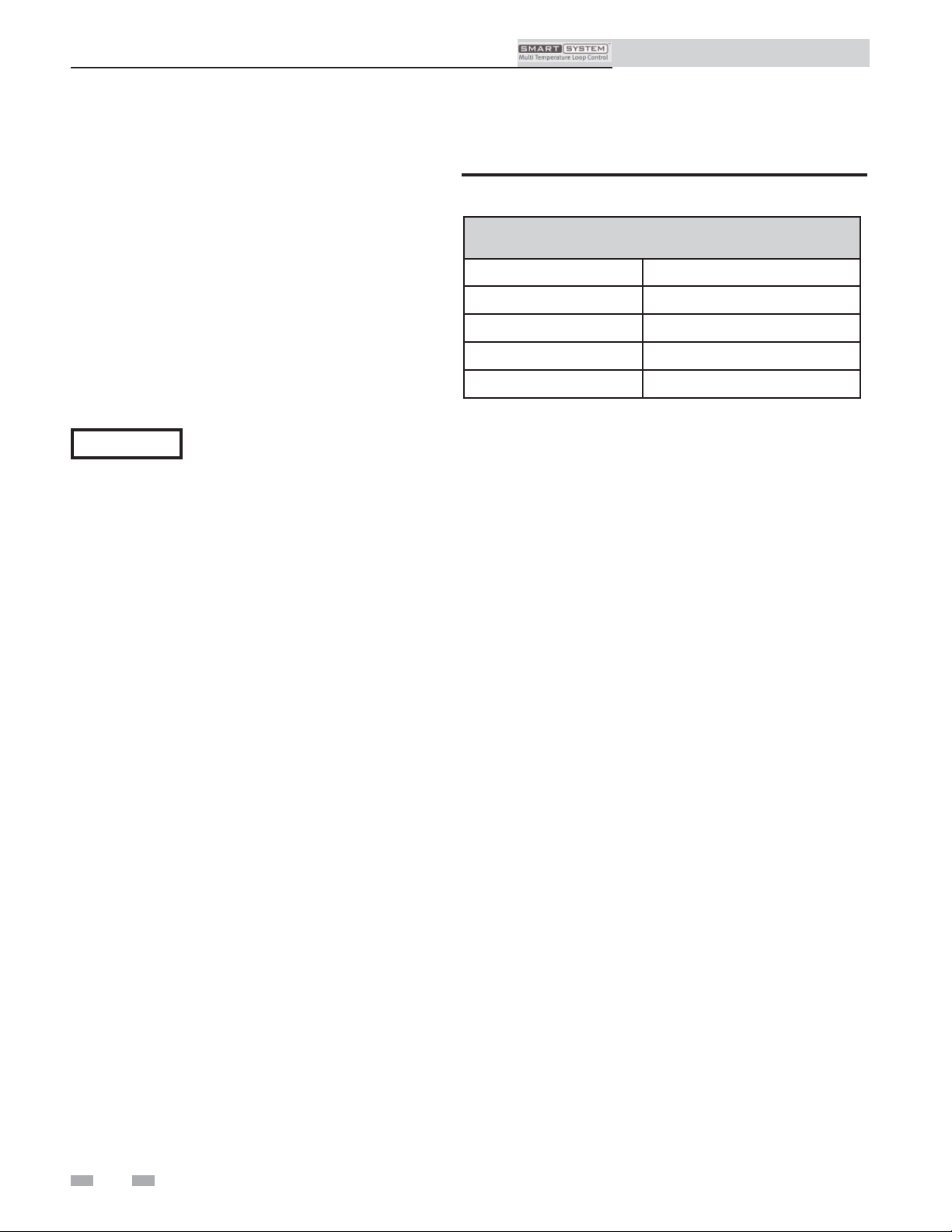
Table 2A 3-Way Valve Requirements
3-Way Valve Requirements
Item Description Limit
Power Supply 24 VAC
Maximum Load .25 Amps
Control Signal 3-Point (Open, Close, Com)
Action Type Floating / Modulating
4. Loop Pumps:
Field supplied. The MTLCB provides 120 VAC power to
operate three (3) loop pumps. The maximum current rating
for each pump cannot exceed 1.8 amps.
2. Loop Temperature Sensors:
The loop temperature sensors measure the temperature
of each loop. Each sensor should be placed on the
discharge side of the loop pump as shown in FIG.’s
2-1 and 2-2 on pages 5 and 6 of this manual. Use
only the three (3) NTC thermistor sensors supplied. If a
replacement sensor is needed, order Lochinvar part
number TST2032. For the best reading, the sensor
should be securely fastened to the pipe and insulated.
3. Mixing Valves:
Field supplied. The MTLCB is designed to control
24 VAC fl oating 3-way mixing valves with open and
close signals. These valves have an actuator (motor)
time from full open to full close. The time in seconds
must be consistent across all 3-way valves installed. For
information on programming the mixing valve time
into the boiler, reference Section 4 , Boiler Parameter
Setup. For 3-way valve requirements, reference Table
2A.
4
Page 5

Loop Control Board Instructions
2 Components and Hydronic Piping (continued)
Figure 2-1_Single Boiler Multi-Temperature
PRESSURE
REDUCING VALVE
BACKFLOW
PREVENTER
MAKE
UP
WATER
AIR SEPARATOR
BALL VALVE
(TYPICAL)
DRAIN POINT
(TYPICAL)
LOOP
SENSOR
(TYPICAL)
PRESSURE
GAUGE
SYSTEM
SUPPLY
SENSOR
EXPANSION
TANK
MAY SUBSTITUTE
LOW LOSS HEADER
TEMPERATURE
LOOP #1
NOT TO EXCEED 4 PIPE DIA.
OR MAX. OF 12" APART
Y-STRAINER
(RECOMMENDED)
BOILER
CIRCULATOR
FLOW CHECK
VALVE
TEMPERATURE
LOOP #2
TEMPERATURE
LOOP #3
DOMESTIC
HOT WATER
CIRCULATOR
MIXING VALVES
(TYPICAL)
HOT
WATER
OUT
ANTI-SCALD
MIXING VALVE
COLD
WATER
IN
NOTICE
NOTICE
UNION
(TYPICAL)
TEMPERATURE /
PRESSURE
GAUGE
DRAIN
BOILER
BOILER
INDIRECT
DHW TANK
INDIRECT
DHW
Please note that these illustrations are meant to show system piping concept only, the installer is responsible
for all equipment and detailing required by local codes.
A system supply sensor MUST BE installed for proper boiler operation to occur.
5
Page 6

2 Components and Hydronic Piping
Figure 2-2_Single Boiler Multi-Temperature DHW Zoned
Loop Control Board Instructions
PRESSURE
REDUCING VALVE
BACKFLOW
PREVENTER
MAKE
UP
WATER
AIR SEPARATOR
BALL VALVE
(TYPICAL)
DRAIN POINT
(TYPICAL)
LOOP
SENSOR
(TYPICAL)
PRESSURE
GAUGE
SYSTEM
SUPPLY
SENSOR
EXPANSION
TANK
MAY SUBSTITUTE
LOW LOSS HEADER
TEMPERATURE
LOOP #1
NOT TO EXCEED 4 PIPE DIA.
OR MAX. OF 12" APART
Y-STRAINER
(RECOMMENDED)
BOILER
CIRCULATOR
TEMPERATURE
LOOP #2
TEMPERATURE
LOOP #3
MIXING VALVES
(TYPICAL)
DOMESTIC
HOT WATER
CIRCULATOR
FLOW CHECK
VALVE
HOT
WATER
OUT
ANTI-SCALD
MIXING VALVE
COLD
WATER
IN
NOTICE
NOTICE
6
UNION
(TYPICAL)
TEMPERATURE /
PRESSURE
GAUGE
DRAIN
BOILER
INDIRECT
DHW TANK
Please note that these illustrations are meant to show system piping concept only, the installer is responsible
for all equipment and detailing required by local codes.
A system supply sensor MUST BE installed for proper boiler operation to occur.
Page 7

3 Wiring Requirements
Loop Control Board Instructions
WARNING
NOTICE
CAUTION
ELECTRICAL SHOCK HAZARD – For
your safety, turn off electrical power supply
before making any electrical connections
to avoid possible electric shock hazard.
Failure to do so can cause severe personal
injury or death.
Wiring must be N.E.C. Class 1.
If original wiring as supplied with boiler
must be replaced, use only type 105°C
wire or equivalent.
Boiler must be electrically grounded as
required by National Electrical Code
ANSI/NFPA 70 – latest edition.
Label all wires prior to disconnection when
servicing controls. Wiring errors can
cause improper and dangerous operation.
Installation must comply with:
1. National Electrical Code and any other national, state,
provincial, or local codes, or regulations.
2. In Canada, CSA C22.1 Canadian Electrical Code Part 1,
and any local codes.
Line voltage connections
1. Connect 120 VAC power wiring to the line voltage
terminal strip in the junction box, as shown in FIG. 3-1
on page 8.
2. Wire the loop pumps (provided by the installer) as shown
in FIG. 3-1.
Loop sensors
1. Install the kit provided loop temperature sensors (see
FIG.’s 2-1 and 2-2).
2. Route the sensor wires through a knockout on the side of
the MTLCB (FIG. 3-1).
3. Connect the loop temperature sensors to the SEN1, SEN2,
and SEN3 terminals on the MTLCB.
Mixing valves
1. Install the mixing valves as shown in FIG.’s 2-1 and 2-2.
2. Route the mixing valve wires through a knockout on the
right side of the MTLCB (FIG. 3-1).
3. Connect the mixing valve wires to terminals MV1, MV2,
and MV3 on the MTLCB.
Wiring of the cascade
Communication between the boiler and the MTLCB
is accomplished using shielded, 2-wire twisted pair
communication cable. Try to keep the cable as short as
possible.
1. Connect one end of the twisted pair wires to Cascade
terminals A and B on the Low Voltage Connection Board
of the boiler (see FIG. 3-2 on page 9).
2. Connect the other end of the twisted pair wires to MTLCB
terminals A and B (FIG. 3-1).
3. Connect the shield wires to one of the shield terminals
on the Low Voltage Connection Board (FIG. 3-2) and the
MTLCB (FIG. 3-1).
NOTICE
The loop pump connections provide 120
VAC power to the pumps at a maximum
current rating of 1.8 amps for each pump.
7
Page 8

3 Wiring Requirements
LOOP SENSOR 1
LOOP SENSOR 2
LOOP SENSOR 3
SEN 2SEN 1
SEN 3
BA
A
B
SHIELD
CASCADE WIRING
VALVE FUSE
1.25 A
5.0 A
P
UMP
F
US
E
P
UM
P
1
P
UM
P
2
P
UM
P
3
N
L
N
N
N
L
L
L
NEUTRAL
LINE
120 V
SUPPLY
LOOP
PUMP 3
LOOP
PUMP 2
LOOP
PUMP 1
FI
E
L
D
S
UP
P
LIE
D
TO
BOILER
3
3-WAY
MIXING
VALVE
2
3-WAY
MIXING
VALVE
1
3-WAY
MIXING
VALVE
CLS
OPN
COM
CLS
OPN
COM
CLS
OPN
COM
FIELD SUPPLIED
COM
CLS
OPN
MV3
OPN
OPN
CLS
CLS
MV2MV1
1
20
VA
C
GND
GROUND
IMG00112
Figure 3-1_Multi-Temperature Loop Control Board (MTLCB)
Loop Control Board Instructions
8
Page 9

Loop Control Board Instructions
3 Wiring Requirements (continued)
Figure 3-2_Terminal Strip Connections to the Boiler’s Low Voltage Connection Board (Knight/Knight XL shown
below for illustration purposes)
IMG00103
LOW VOLTAGE CONNECTION BOARD
ENABLE
CONTACTS
9
Page 10

Loop Control Board Instructions
4 Boiler Parameters Setup
Once the wiring requirements of all the MTLCB components are complete, the next step is to adjust the following parameters
through the boiler’s display:
• Cascade Address
• Loop Temperature Settings
• 3-Way Valves
• Pumps
Power ON the boiler and place into Shutdown Mode, leaving the MTLCB powered OFF. With the boiler in Shutdown Mode,
all calls for heat are disabled and the parameters listed above can be adjusted.
Cascade communication setup
When the MTLCB is used with a single boiler, the boiler must
be programmed as a Cascade Leader by setting its Cascade address to 0.
Figure 4-1_Cascade Screen
To access cascade address:
1. While on the Menu Selection Screen, select [CONTROL
MODES].
2. In the Control Modes Menu (FIG. 4-1), select [CASCADE
ADDRESS] and set to [0].
3. Press the RIGHT SELECT [SAVE] key.
4. Press the [HOME] key to exit and download all parameters.
To adjust the set points for each space heat/loop, reference the Service Manual for a detailed explanation.
The 3-Way Mixing Valve Time can be accessed as shown below:
3-way valve setup
NOTICE
1. Press and hold the LEFT SELECT [MENU] key.
2. Enter the pass code.
3. Scroll down and select [TEMPERATURE SETTINGS].
4. Scroll down and select 3-Way Valve Time by pressing the NAVIGATION dial (FIG. 4-10.
5. Scroll to the intended value.
6. Press the RIGHT SELECT [SAVE] key.
7. Exit one level.
Please note that the brackets ([]) denote screen status.
Once all the parameters have been adjusted for the application, power ON the MTLCB. TX and RX LED’s will light up to signify
data is being sent and received from the boiler’s control. With successful communication, the SH1, SH2, and SH3 temperatures
can be read with a clockwise rotation of the NAVIGATION dial (see FIG. 4-3). If successful communication does not occur,
reference FIG. 4-1 for set up of the Cascade address.
Figure 4-2_SH1, SH2, and SH3 Screen
Figure 4-3_3-Way Valve Time Screen
10
Page 11

4 Boiler Parameters Setup (continued)
Figure 4-4_System Pump Delay Screen
Loop Control Board Instructions
24-hour pump in-activity operation
In the event there is not a call for heat in 24 hours, the loop pump will operate for the time of the system pump delay setting.
To set time for SYS PUMP DELAY:
1. While still on the Menu Selection Screen, scroll down and select [CIRCULATION PUMPS] by pressing the NAVIGATION
dial.
2. In the CIRCULATION PUMPS Menu (FIG. 4-4), select [SYS PUMP DELAY], scroll to the intended time value and press the
RIGHT SELECT [SAVE] key.
11
Page 12

5 Basic Operation
Loop Control Board Instructions
The MTLCB serves as the controlling device for up to three
(3) individual loops, branching off the system loop of a space
heating system. It will control each loop pump and mixing
valve position in order to satisfy the set point for that loop.
By installing the sensors (provided in kit) on the pipe, after the
pump, a mixed temperature is relayed to the boiler display.
Each thermostat input to the boiler should receive a loop
temperature feedback for proper operation. Using this input,
the MTLCB operates the 3-way valve to the correct position
for mixed water supply. The pump will run continuously
with the valve positioning until the thermostat set point is
met or a Protection Mode is active.
When demands of more than one loop are active, the system
set point is maintained at the highest space heat set point
enabled. All enabled loops are actively satisfi ed together, with
up to three (3) different set points mixing down for each set
point temperature below the system.
NOTICE
Once a thermostat demand is enabled, the pump will run
for one (1) minute to stabilize loop temperature before
opening to system water. Note: For smaller systems, the
use of Ramp Delay is recommended to prevent short cycling
and extend runtime. At this time the 3-way valve will adjust,
open to a calculated initial position based on the differential
of the sensed temperature and set point. The MTLCB will
continue to raise the mixed temperature of the loop toward its
individual set point, while continuously relating to the loop’s
sensor input by a specifi c algorithm.
At the end of a loop demand cycle, the pump powers off, and
the valve will move to the fully closed position.
At the beginning of successful
communication, all 3-way valves will see
a signal to close 125% of the time value
entered in the General Setup Section,
FIG. 4-3 on page 10.
Protections
Initial
In the event the sensed temperature continues to exceed the
set point (set point + offset - 2°F, but within the set point +
20°F) for a given loop, a Protection Mode is entered to stop
excessive temperatures from being reached. To prevent the
loop temperature from exceeding this range, the following
stages are enacted:
1. The pump active on the loop exceeding the set point
temperatures is powered off.
2. The mixing valve is adjusted from the current position,
plus 25% to the closed position.
3. The pump is powered ON for two (2) minutes.
4. If the temperature has not dropped below the [set point +
offset - 2°F], the pump is turned OFF.
The control will automatically reset the demand as active once
the sensor input is below the [set point + offset - 2°F].
Error Mode
If the sensed temperature rises above set point + 20°, the
display of the boiler will present the sensor input with an
exclamation mark (ex. 128°F!). The following protection
algorithm will begin to prevent a lockout of the loop:
1. If running, the pump will immediately power off and the
3-way valve is adjusted 125% in the closed direction.
2. Once the close signal ends, the pump is powered back on
for two (2) minutes. Within this time, the sensed
temperature must drop below [set point + offset] or the
pump will be powered off.
3. As a result, the temperature will drop below [set point +
offset] and the error code (ex. 128°F!) is removed.
With the Initial and Error Mode Protections, the valve is fully
closed to reduce the loop temperature by preventing continued
hot water supply from the system. If the temperature sensed
is not reduced within the steps listed above, the MTLCB will
lockout this loop until temperatures below [set point + offset]
are reached. During these scenarios, ensure the physical
movement of the 3-way valve in the event the system needs
to be repaired.
12
Page 13

5 Basic Operation (continued)
Forced Change
It is necessary for the MTLCB to sense a temperature change
of 2°F within the time of a call for heat and the initial
position of the 3-way valve. This is a two-fold protection
where the MTLCB protects the loop from continued normal
operation when it cannot calculate the sensitivity of the valve
movement needed.
As a secondary operation, the sequence below protects
the loop when the loop temperature sensor is connected
to the MTLCB but not installed properly, not installed, or
malfunctioning.
1. With a call for heat the pump turns on.
2. The 3-way valve moves to the initial open position after the
pump is on for one (1) minute.
3. If after three (3) minutes the initial position does not
create a 2°F change in sensed temperature, the 3-way
valve is moved to the closed position.
Loop Control Board Instructions
4. After two (2) minutes of closure, the 3-way valve is
opened to the initial position.
5. Repeat Steps #3 and #4.
6. Once the 3-way valve is moved to the closed position, the
loop is locked out for the duration of the call for heat.
7. The lockout continues for 30 minutes after the call for heat
has ended.
8. After 30 minutes, the next call for heat will begin at Step
#1.
Please note, the fi rst two (2) steps are normal operation and
at Step #3, if a 2°F change in temperature is not sensed, the
protection process will begin. If at any point a 2°F change is
sensed, normal operation will resume.
13
Page 14

NOTES
14
Page 15

NOTES
15
Page 16

Revision Notes: Revision A (ECO #C08954)
initial release.
Revision B (ECO C10236) refl ects the update of
the control image in Figure 3-1 on page 8.
LCB-I-O Rev B
04/12
 Loading...