


Windows PLC
Programmer Manual
2008/2 Ver V04.00.000(4408420002)
Leading Numerical Controller
LNC Technology Co., Ltd.
LNC CORP., LTD. |
I |

 Windows PLC
Table of Content
Table of Content
1 |
INTRODUCTION OF BUILT-IN PLC SOFTWARE |
.................................1 |
||
2 |
PLC I/O SETTING .................................................................................. |
3 |
||
|
2.1 PLC PROGRAM SOFTWARE INTERFACE............................................................................... |
5 |
||
|
|
2.1.1 |
Software Operation Instruction:.................................................................................... |
5 |
|
2.2 PLC PROGRAM FEATURES & STRUCTURE........................................................................... |
6 |
||
|
2.3 Functions of Shortcut Keys....................................................................................................... |
10 |
||
|
2.4 |
Component Shortcut Keys........................................................................................................ |
12 |
|
|
2.5 |
PLC Contact Definition.............................................................................................................. |
27 |
|
|
|
2.5.1 |
Normal Open Contact -| |- .......................................................................................... |
27 |
|
|
2.5.2 |
Normal Close Contact -|/|- .......................................................................................... |
27 |
|
|
2.5.3 |
Normal Open Coil....................................................................................................... |
28 |
|
|
2.5.4 |
Normal Closed Coil..................................................................................................... |
28 |
|
|
2.5.5 |
Positive Edge Triggered Coil ( ↑ ) ........................................................................... |
28 |
|
|
2.5.6 |
Negative Edge Triggered Coil ( ↓ ).......................................................................... |
29 |
|
|
2.5.7 |
Latch Coil (S).............................................................................................................. |
29 |
|
|
2.5.8 |
Unlatch Coil (R) .......................................................................................................... |
30 |
|
|
2.5.9 |
Timer Relay ................................................................................................................ |
30 |
|
|
2.5.10 |
Up Counter ................................................................................................................. |
31 |
|
|
2.5.11 |
Down Counter............................................................................................................. |
31 |
|
|
2.5.12 |
Ring Up Counter......................................................................................................... |
32 |
|
|
2.5.13 |
Ring Down Counter .................................................................................................... |
33 |
|
|
2.5.14 |
Reset Counter ............................................................................................................ |
33 |
|
|
2.5.15 |
Add Instruction (Add).................................................................................................. |
34 |
|
|
2.5.16 |
Subtract Instruction (Subtract).................................................................................... |
34 |
|
|
2.5.17 |
Multiply Instruction...................................................................................................... |
35 |
|
|
2.5.18 |
Divide Instruction (Divide) .......................................................................................... |
35 |
|
|
2.5.19 |
AND Instruction .......................................................................................................... |
36 |
|
|
2.5.20 |
OR Instruction (Or) ..................................................................................................... |
37 |
|
|
2.5.21 |
XOR Instruction (Exclusive Or) .................................................................................. |
38 |
|
|
2.5.22 |
CMP Instruction (Compare, Larger Than) .................................................................. |
39 |
|
|
2.5.23 |
CMP Instruction (Compare, Smaller Than) ................................................................ |
39 |
|
|
2.5.24 |
Compare Instruction, Equal To ................................................................................... |
40 |
|
|
2.5.25 |
SRAM Read Instruction (SRAM Read) ...................................................................... |
40 |
LNC Technology Co., Ltd. |
I |

Windows PLC |
|
|
Table of Content |
|
|
2.5.26 SRAM Write Instruction (SRAM Write)....................................................................... |
41 |
|
2.5.27 |
MOVE Instruction ....................................................................................................... |
41 |
2.5.28 SCH Instruction (Data Search)................................................................................... |
42 |
|
2.5.29 |
JMP Instruction (Jump)............................................................................................... |
42 |
2.5.30 Ladder Figure Call Subroutine JSR Instruction (Jump Subroutine) ........................... |
43 |
|
2.5.31 Ladder Figure Subroutine Return Instruction (Return Subroutine) ............................ |
43 |
|
2.5.32 |
Label........................................................................................................................... |
43 |
2.5.33 Ladder Figure END Instruction................................................................................... |
44 |
|
2.6 PLC PROGRAM Find Function ................................................................................................ |
45 |
|
2.7 Functions of the keys of the mouse .......................................................................................... |
46 |
|
APPENDIX A IMPORT OF CUSTOM LOGO OPERATION ...................... |
47 |
|
II |
LNC Technology Co., Ltd. |

 Windows PLC
Introduction of Built-in PLC Software
1 Introduction of Built-in PLC Software
Being the industry-leading developing platform, LNC controllers not only provide built-in PLC modules from small to medium sizes, but also provide the ladder figure editing software of PLC Programmer for Windows operating system.
The Input/Output points supported by PLC modules can be applied as the I/O signals. The software also provides mathematical abilities to measure time or numbers, logistics, to perform operations, and to compare, etc. for the need of every kinds of sequence control.
PLC programmer of this version can be applied to two types of ladder programs:
1.Dual-system controllers (Ex. LNC-T800 Lathe controller) Ladder file name is CNC.MLC.
2.Single system controllers (Ex. LNC-600 Series, LNC-520 Series, LNC-510i Series, LNC-310i Series Ladder file name is CNC.LAD.
This chapter describes how to set hardware ports & their corresponding I/O points of PLC.
Chart 1 Dual-system PLC I/O Data Types
Data Type |
Name |
Q’ty |
|
|
Definitions |
||
|
|
|
|
|
|||
|
I |
5120 |
Digital input ------------------- |
I0 ~ I5119 |
|||
|
|
|
|
|
|||
|
O |
5120 |
Digital output ---------------- |
O0 ~ O5119 |
|||
Boolean |
|
|
|
|
|||
A |
5120 |
Internal contact ---------------- |
A0 ~ A5119 |
||||
|
|
|
|
|
|||
|
S |
5120 |
Internal contact (Status)------- |
S0 ~ S5119 |
|||
|
|
|
|
|
|||
|
C |
5120 |
Internal contact ( Command)------- |
C0 ~C5119 |
|||
|
|
|
|
|
|
||
|
Timer |
256 |
Timer ------- |
TM0 ~ TM255 |
|
||
|
( TIM ) |
Timer unit type |
10 ms, 0.1 sec,1 sec |
||||
|
|
||||||
|
|
|
|
|
|||
|
Counter |
256 |
Counter--------- |
CT0 ~ CT255 Counting method: |
|||
|
( CNT ) |
Up, Down, Reset, Ring Up, & Ring Down Counter |
|||||
Integer |
|
||||||
|
|
|
|
|
|
||
Data Register |
1024 |
Data Register |
D0 ~ D1023 |
||||
|
|||||||
|
( DReg ) |
Data is preserved after shut down. |
|||||
|
|
||||||
|
|
|
|
|
|
||
|
Register |
1024 |
Register----------------- |
|
R0 ~ R1023 |
||
|
( Reg ) |
Data is cleared after shut down. |
|||||
|
|
||||||
|
|
|
|
|
|
|
|
LNC Technology Co., Ltd. |
1 |

 Windows PLC
Introduction of Built-in PLC Software
Chart 2 Single-system PLC I/O Data Types
Data Type |
Name |
Q’ty |
|
|
Definitions |
||
|
|
|
|
|
|||
|
I |
512 |
Digital input ------------------- |
I0 ~ I511 |
|||
|
|
|
|
|
|||
|
O |
512 |
Digital output ---------------- |
O0 ~ O511 |
|||
Boolean |
|
|
|
|
|
||
A |
512 |
Internal contact ---------------- |
|
A0 ~ A511 |
|||
|
|
|
|
|
|
|
|
|
S |
512 |
-------Internal contact (Status) |
S0 ~ S511 |
|||
|
|
|
|
|
|||
|
C |
512 |
Internal contact (Command)------- |
C0 ~C511 |
|||
|
|
|
|
|
|
||
|
Timer |
256 |
-------Timer |
TM0 ~ TM255 |
|
||
|
( TIM ) |
Timer unit type |
10 ms, 0.1 sec, 1 sec |
||||
|
|
||||||
|
|
|
|
|
|||
|
Counter |
256 |
Counter--------- |
CT0 ~ CT255 Counting method: |
|||
|
( CNT ) |
Up, Down, Reset, Ring Up, & Ring Down Counter |
|||||
Integer |
|
||||||
|
|
|
|
|
|
||
Data Register |
256 |
Data Register |
D0 ~ D255 |
||||
|
|||||||
|
( DReg ) |
Data is preserved after shut down. |
|||||
|
|
||||||
|
|
|
|
|
|
||
|
Register |
256 |
Register----------------- |
|
R0 ~ R255 |
||
|
( Reg ) |
Data is cleared after shut down. |
|||||
|
|
||||||
|
|
|
|
|
|
|
|
2 |
LNC Technology Co., Ltd. |

 Windows PLC
PLC I/O Setting
2 PLC I/O Setting
Except for LNC-310i Series, which does not require the PLCIO.cfg file, for the rest of other models, the PLCIO.cfg file can be found in the MACHINE directory. This file allows users to set the actual I/O points which correspond to logical I/O points in CNC. Below is an example of I/O signal setting by editing a PLCIO.cfg file in the machine:
InputSignalInverse=0 |
|
// To inverse I point or not; 0= No,1= Yes |
|||
OutputSignalInverse=0 |
|
// To inverse O point or not; 0= No, 1= Yes |
|||
BaseAddress=0x200 |
|
// Base address |
|
||
Set1Slave1=1 |
|
|
// If to use Slave 1 of Set1, 0= No, 1= Yes |
||
Set1Slave2=0 |
|
|
// If to use Slave 2 of Set1, 0= No, 1= Yes |
||
Set2Slave1=1 |
|
|
// If to use Slave 1 of Set2, 0= No, 1= Yes |
||
Set2Slave2=0 |
|
|
// If to use Slave 2 of Set2, 0= No, 1= Yes |
||
// Field [I or O] |
[NUMBER] |
[SET] |
[ADDRESS] |
[Add remarks here] |
|
I |
0 |
1 |
0x200 |
|
|
I |
8 |
1 |
0x201 |
// No blank is allowed between lines. |
|
I |
16 |
1 |
0x202 |
// Either I or i |
|
I |
24 |
1 |
0x203 |
// Either O or o |
|
I |
32 |
1 |
0x204 |
// SET=1 refers to SET1, SET=2 refers to SET2 |
|
I |
40 |
2 |
0x200 |
|
|
I |
48 |
2 |
0x201 |
|
|
I |
56 |
2 |
0x202 |
|
|
I |
64 |
2 |
0x203 |
|
|
I |
72 |
2 |
0x204 |
|
|
O |
0 |
1 |
0x200 |
// O points must be even numbers. |
|
O |
8 |
1 |
0x201 |
|
|
O |
16 |
1 |
0x202 |
|
|
O |
24 |
1 |
0x203 |
|
|
O |
32 |
1 |
0x204 |
|
|
O |
40 |
1 |
0x205 |
|
|
O |
48 |
2 |
0x200 |
|
|
O |
56 |
2 |
0x201 |
|
|
O |
64 |
2 |
0x202 |
|
|
O |
72 |
2 |
0x203 |
|
|
LNC Technology Co., Ltd. |
3 |

 Windows PLC
PLC I/O Setting
I |
80 |
11 |
0x200 |
// SET=11 presents the first 4 points of Local IO, 12 presents the later |
4 points. Set only 4 points each time, and put them together for claiming. |
||||
I |
84 |
12 |
0x200 |
// 0x200:0~7,0x201:8~15 |
O |
80 |
11 |
0x201 |
// 0~7 12~15 : Local Input |
I |
88 |
12 |
0x201 |
// 8~11 : Local Output |
4 |
LNC Technology Co., Ltd. |

 Windows PLC
PLC I/O Setting
2.1 PLC PROGRAM SOFTWARE INTERFACE
2.1.1Software Operation Instruction:
Method 1
1.Go to the PLC installation file such as C:\Program Files\PLC Programmer\ (Default).
2.Execute the PLCProgrammer.exe file & PLC Program screen as shown in <Figure 1>.
Method 2
1.Click Start→Program Files→ PLC Programmer
2.Click the shortcut PLC Programmer
3.The PLC Program screen is shown as <Figure 1>.
<Figure 1> PLC PROGRAM Software Interface
LNC Technology Co., Ltd. |
5 |

 Windows PLC
PLC I/O Setting
2.2 PLC PROGRAM FEATURES & STRUCTURE
6 |
LNC Technology Co., Ltd. |
 Windows PLC
PLC I/O Setting
Software interface screen is shown as <Figure 2>
Shortcut Keys |
Component |
|
Shortcut Keys |
Ladder Edit |
|
PLC Debug Message
Figure 2 Software Interface
LNC Technology Co., Ltd. |
7 |

 Windows PLC
PLC I/O Setting
PLC PROGRAM: Steps to create a new project is shown as <Figure 3>
I.Click Project.
II.Click New.
III. Select single (LAD) or dual system (MLC) in the Project Setting dialog box. IV. After selection is finished, click OK to create a new project.
V.The new project is created as shown in Figure 4.
 1.Click Project 2.Click New
3.Select MLC or LAD
4.Click OK to create a new project
<Figure 3>PLC PROGRAM: Steps to Create a New Project
8 |
LNC Technology Co., Ltd. |

 Windows PLC
PLC I/O Setting
1st -]END[-
2nd -]END[-
* Level 1 = The 1st line to the 1st -]END[-
(Cycle time is 3ms)
* Level 2 = The 1st -]END[- to the 2nd -]END[-
<Figure 4> Complete the Steps of Creating a New Project.
LNC Technology Co., Ltd. |
9 |

 Windows PLC
PLC I/O Setting
2.3 Functions of Shortcut Keys
New Create a new project.
Open Open an old project.
Save Save the current project.
Print Print the current project.
Copy Copy one line Unable to copy single component .
Cut Cut one line Unable to cut single component .
Paste Paste one line Unable to paste single component .
Insert One Line Add a new line (Shift + Ins).
Insert One Line – Horizontal Line Insert a horizontal line (Ctrl + Ins ).
Insert One Line – End Line Insert an end line.
Insert One Line – Label Line Insert a label line.
Delete – Component Delete a component (Del).
Delete – Vertical Line Delete a vertical line (Shift+Del).
Delete – Mark Line Delete the entire line (Ctrl+Del).
Check Check if the ladder is correct or not.
Setting – Symbol Edit symbols, as shown in <Figure 5>.
Setting – String Edit word strings.
<Figure 5> Define Symbols
10 |
LNC Technology Co., Ltd. |

 Windows PLC
PLC I/O Setting
Insert one line (Shift + Ins)
Insert a horizontal line (Ctrl + Ins)
Insert an end line
Insert a label line
Check
<Figure 6> Ladder Edit Shortcut Keys
LNC Technology Co., Ltd. |
11 |
 Windows PLC
PLC I/O Setting
2.4 Component Shortcut Keys
 Cursor shortcut key Right-click the mouse and drag to select.
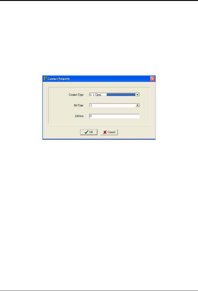
 Contact shortcut key Left-click the Contact shortcut key, and the Contact Property dialog box will appear as
<Figure 7>.
<Figure 7> Select a Contact Type
Select a contact type as shown in <Figure 8> Open Normal open contact.
Close Normal close contact. Timer Open Timer is triggered.
Timer Close Timer is NOT triggered. Counter Open Counter is triggered. Counter Close Counter is NOT triggered.
Component Types for selection (Only limited to Open or Close type) as <Figure 9> I PLC obtains external inputs for the information of peripheral status.
O PCL outputs signals to external peripherals. C S Interface between NC and PLC. A PLC internal auxiliary contacts.
12 |
LNC Technology Co., Ltd. |
 Loading...