

Page 1

LiveU Live Video
Uplink System
User Guide
(
6.3
DOC00032
LU60 and LU70)
Version
Part Number:
Page 2
LiveU Live Video Uplink System User Guide
About This Guide
This guide describes the LU60/LU70 liv e video uplink sys tem and provides
basic operation information f o r camera operators. It describes the hardware
that is included and how to use the system in order to broadcast live
streaming video for a multitude of purposes.
NOTE
This guide assumes that operators hav e basic computer knowledge and are
familiar with any video equipment being used (cameras, m icr ophones and so
on).
The guide contains the following chapters:
• Chapter 1, Overview, page 13, introduces the LU Live Video Uplink unit
Advanced operations intended fo r technical personnel and system
administrators are outsid e o f the scope o f this guide.
and describes its hardware compon en ts.
• Chapter 2, Getting Started, page 19, describes how to get started using
the LU, including powering on, connecting the camera, connecting to the
LU-1000 and broadcastin g ( playing).
• Chapter 3, LU User Interface, page 33, describes the main LU win dow
and the options that it provides.
• Chapter 4, Successful Video Transmission, page 47, describes so m e o f
the aspects on which successful transmission of a high-quality audio/video
stream depend, such as video resolution, target resolution, bitrate, CODEC
and so on.
• Chapter 5, File Transfer, page 59, describ es how to use the LU to
transfer files from the field directly to the LU-1000 server.
• Chapter 6, Store & Forward, page 63, describes how to use the LU
Store & Forward feature to record video sessions, forward them to the
LU-1000 server, or simultaneously record and forward files from the field
directly to the LU-1000 server.
2
Page 3
About This Guide
y instructions in
• Chapter 7, Configuration and Settings, page 73, describes how to
adjust the automatic setup of the LU, if required, and how to define it as
an Access Point.
• Chapter 8, LU Remote Contr ol, page 105, describes how to use the
Remote Control application to con trol LU devices remotely.
• Appendix A, LU Battery, page 119, describes how to check the char ge,
to change and to replace the LU battery .
• Appendix B, LU Back pack, page 125, describes the LU backpack.
• Appendix C, Troubleshooting, page 133, describes how to troubleshoo t
various issues that may occur on the LU .
CAUTION
CAUTION
For safety re as ons, pleas e read carefully the safet
Appendices B and D.
• It is recommended to use the device in side the LU
backpack.
• When using the device outside the LU backpack, follow the
safety instructions in Appendix D in order to avoid shorting
the battery.
• Appendix D, Safety and Maintenance, page 139, describe s ho w to
maintain the LU and how to handle potential hazards.
• Appendix E, Limitation of Liability and Warranty, page 143, describes
the limitations on liability and warranty.
• Appendix F, FCC Compliance, page 145
Additional Doc umen tati o n
In addition to this guide, a comprehensive operator’s manual for the LU-1000
server is available. The LU-1000 server manual contains detailed instructions
for interfacing with the L U's video output and hands-on instruction for
broadcasting via a number of different applications.
The LiveU Xtender option can also be used with LU60/LU70 units to increase
network reception and provide additional resiliency for live video tr a nsmission
in extreme scenarios. For mor e details, see the LiveU Xtender User Guide.
3
Page 4

LiveU Live Video Uplink System User Guide
Table of Contents
About This Guide ........................................................................................................ 1
Table of Figures........................................................................................................... 7
Support and Contacting Information ..................................................................... 11
Chapter 1: Overview................................................................................................ 13
Introduction .................................................................................................................... 13
System Overview ........................................................................................................... 14
Wireless Connectivity .................................................................................................... 15
LU as an Access Point ............................................................................................ 16
LU Device Types ............................................................................................................. 16
What’s in the Box? ......................................................................................................... 17
LU60/LU70 Hardware Components .................................................................... 17
Chapter 2: Getting Started ...................................................................................... 19
Step 1, Turning On the LU Device ............................................................................... 20
LU60/LU70 – Turning On the Device .................................................................... 20
Main User Window ................................................................................................. 22
Step 2, Connecting the Video Camera ................................................................... 23
LU60/LU70 – Connecting the Camera ............................................................... 24
Step 3, Connecting to the LU-1000 ............................................................................ 26
Connecting – Transmission Test ........................................................................... 28
After Connection ................................................................................................... 28
Step 4, Playing................................................................................................................ 30
Step 5, The Next Step .................................................................................................... 30
Checking Interface Q uality ......................................................................................... 31
Chapter 3: LU User Interface ................................................................................... 33
LU Touch-screen Interface........................................................................................... 34
Video Feed ..................................................................................................................... 35
Camera Connectivity Icon ......................................................................................... 36
Battery Indicator Icon ................................................................................................... 37
Transmission Quality ...................................................................................................... 38
IFB Indicator .................................................................................................................... 40
Status Indicator .............................................................................................................. 41
Rotate Screen ................................................................................................................ 43
Unlock/Lock Button ....................................................................................................... 42
4
Page 5

Table of Contents
Options Button ............................................................................................................... 44
Upload Button ................................................................................................................ 44
Connect/Reconnect Button ....................................................................................... 44
Connect Button ...................................................................................................... 43
Reconnect Button .................................................................................................. 44
Transmit Button ............................................................................................................... 45
Profiles .............................................................................................................................. 46
Platform and Unit Name .............................................................................................. 45
Chapter 4: Successful Video Tr a n smission ............................................................. 47
Overview ......................................................................................................................... 47
Target Audience .................................................................................................... 47
Profiles Window .............................................................................................................. 48
Changing the Profile ..................................................................................................... 50
Profile Descriptions ................................................................................................. 51
Changing a Profile’s Resolution .................................................................................. 55
Resolution Descriptions .......................................................................................... 56
Chapter 5: File Transfer ............................................................................................. 59
Transferring Files ............................................................................................................. 59
Chapter 6: Store & Forward ...................................................................................... 63
Storing and Forwarding Files........................................................................................ 63
Chapter 7: Configuration and Settings ................................................................... 73
Purpose and Scope ...................................................................................................... 73
Options Button ............................................................................................................... 75
Interfaces ........................................................................................................................ 76
Defining an Interface ............................................................................................ 77
Defining a Wi-Fi Interface ..................................................................................... 79
Access Point ............................................................................................................ 83
Xten der W i -Fi Link.................................................................................................... 86
Manual Roaming.................................................................................................... 88
Servers.............................................................................................................................. 90
Settings ............................................................................................................................ 93
Media ....................................................................................................................... 93
General .................................................................................................................... 95
xTender ..................................................................................................................... 98
Utilities ....................................................................................................................... 99
Input Media ........................................................................................................... 101
5
Page 6

LiveU Live Video Uplink System User Guide
Startup .................................................................................................................... 102
Support .......................................................................................................................... 104
Power ............................................................................................................................. 105
Chapter 8: LU Remote Control .............................................................................. 105
Introducing Remote Control ..................................................................................... 105
Installing the Remote Control Application ............................................................. 106
Configuring Remote Control ..................................................................................... 108
Launching Remote Control ....................................................................................... 110
Controlling an LU Remotely ....................................................................................... 112
Remote Control Main Window .......................................................................... 112
Controlling an LU .................................................................................................. 113
Remote Viewing and Controlling Mode ......................................................... 114
What Cannot be Controlled Remotely ................................................................... 117
Appendix A: LU Battery ......................................................................................... 119
The LU60/LU70 Battery ................................................................................................ 119
Checking the LU60/LU70 Battery Charge ........................................................ 120
Charging the LU60/LU70 Battery ....................................................................... 121
Changing the LU60/LU70 Battery ...................................................................... 122
Appendix B: LU Backpack .................................................................................... 125
The LU60/LU70 Backpack ........................................................................................... 125
How to Insert the LU Unit into the Back p a c k ................................................... 127
LU Backpack – Additional Features .................................................................. 129
Connecting the Camera .................................................................................... 129
The LU60/LU70 Lightweight Backpack ..................................................................... 131
Appendix C: Troubleshooting ............................................................................... 133
Appendix D: Safety and Maintenance................................................................ 139
Safety Information ....................................................................................................... 139
Potential Hazards ........................................................................................................ 141
Appendix E: Limitation of Liability and Warranty ................................................ 143
Limitation of Liability and Warranty.......................................................................... 143
Appendix F: FCC Compliance ............................................................................. 145
6
Page 7

Table of Figures
Table of Figures
Figure 1: Solution Architecture ........................................................................................... 14
Figure 2: Power S wi tch On .................................................................................................. 21
Figure 3: PC IN Connection ................................................................................................ 21
Figure 4: LU Main Us er Interface – With Camera ............................................................ 22
Figure 5: LU Main Us er Interface – Without Ca mera ...................................................... 23
Figure 6: LU60/LU70 with SDI Camera Connection ........................................................ 24
Figure 7: LU60/LU70 with DV, HDMI and Analog Camera Connection ...................... 24
Figure 8: LU Video Uplink Unit Connections ..................................................................... 25
Figure 9: Connecting to an Interface ............................................................................... 26
Figure 10: Connecting Status Indicator ............................................................................ 27
Figure 11: Interface Connection Failed ........................................................................... 27
Figure 12: Connecting – Transmission Test ....................................................................... 28
Figure 13: Profile Parameters .............................................................................................. 28
Figure 14: Unsupported Resolution .................................................................................... 29
Figure 15: Transmission Strength ......................................................................................... 30
Figure 16: Camera Disconnected or Off.......................................................................... 30
Figure 17: Interface Table ................................................................................................... 31
Figure 18: LU Live Video Uplink User Interface ................................................................. 34
Figure 19: Video Feed .......................................................................................................... 35
Figure 20: Video Feed is Always Displayed ...................................................................... 36
Figure 21: Camera Tool Tip ................................................................................................. 37
Figure 22: Battery Status Tool Tip – Time Remaining ....................................................... 37
Figure 23: Battery Status Tool Tip ........................................................................................ 38
Figure 24: Transmission Quality ........................................................................................... 38
Figure 25: IFB Configuration Window ................................................................................ 40
Figure 26: IFB Channel Open .............................................................................................. 41
Figure 27: Locking and Unloc king the Touch-screen ..................................................... 42
Figure 28: Reconnection Message .................................................................................... 44
Figure 29: Platform and Unit Name ................................................................................... 45
7
Page 8

LiveU Live Video Uplink System User Guide
Figure 30: Profiles Window ................................................................................................... 49
Figure 31: Profiles Window ................................................................................................... 50
Figure 32: Interview Profile .................................................................................................. 51
Figure 33: Balanced Profile ................................................................................................. 53
Figure 34: Max Quality Profile ............................................................................................. 54
Figure 35: Changing a Profile’s Resolution ....................................................................... 56
Figure 36: LU File Tra n sfer ..................................................................................................... 60
Figure 37: Completed File Transmission ............................................................................ 61
Figure 38: Camera Disconnected or Off ......................................................................... 61
Figure 39: Store Session Configuration .............................................................................. 64
Figure 40: Virtual Keyboard ................................................................................................ 64
Figure 41: Store Session in Progress .................................................................................... 65
Figure 42: Store Error – No Video Input ............................................................................. 66
Figure 43: Warning Mes sage – Not Enough Space ........................................................ 66
Figure 44: Forward Session Configuration ........................................................................ 66
Figure 45: Forward Browse .................................................................................................. 67
Figure 46: Forward Icon ....................................................................................................... 67
Figure 47: Forward completed message ......................................................................... 68
Figure 48: Store & Forward Session Configuration .......................................................... 68
Figure 49: Virtual Keyboard ................................................................................................ 69
Figure 50: Store & Forward Session in Progress ................................................................ 70
Figure 51: Store & Forward Session – server is busy ......................................................... 71
Figure 52: Setup Options ..................................................................................................... 74
Figure 53: Configuration – Interface Table ...................................................................... 75
Figure 54: Interface (A) or (B) ............................................................................................. 76
Figure 55: Interfac es ............................................................................................................. 77
Figure 56: Guaranteed-rate Interface Option ................................................................ 78
Figure 57: Wireless Network Connection .......................................................................... 79
Figure 58: Wi-Fi Interfaces .................................................................................................... 80
Figure 59: Available Wi-Fi Interfaces ................................................................................. 80
Figure 60: Wireless Network Key ......................................................................................... 81
8
Page 9

Table of Figures
Figure 61: Wi-Fi Connection Order .................................................................................... 82
Figure 62: Defining an Access Point – 1 ............................................................................ 83
Figure 63: Defining an Access Point – 2 ............................................................................ 84
Figure 64: Defining an Access Point – 3 ............................................................................ 84
Figure 65: Defining an Access Point – 4 ............................................................................ 86
Figure 66: Xtender WiFi Link ................................................................................................. 87
Figure 67: Remote Antenna Wi-Fi ‒ Xtender .................................................................... 87
Figure 68: Manual Roaming – 1 ......................................................................................... 88
Figure 69: Manual Roaming – 2 ......................................................................................... 89
Figure 70: Servers .................................................................................................................. 90
Figure 71: Server Definitions ................................................................................................ 91
Figure 72: Virtual Keyboard ................................................................................................ 91
Figure 73: Configuration Window – Media Options ....................................................... 92
Figure 74: Configuration Window – General Options .................................................... 95
Figure 75: Touch Screen Configuration ............................................................................ 96
Figure 76: Virtual Keyboard ................................................................................................ 96
Figure 77: Network Connections Window ........................................................................ 97
Figure 78: WiMax Configuration ......................................................................................... 98
Figure 79: Configuration Window – Xtender Options .................................................... 98
Figure 80: Utilities Settings .................................................................................................... 99
Figure 81: Input Media Settings ........................................................................................ 101
Figure 82: Startup Operation Settings ............................................................................. 102
Figure 83: Getting Remote Support from LiveU ............................................................ 103
Figure 84: Power Options .................................................................................................. 104
Figure 85: Installing Remote Control – 1 ......................................................................... 106
Figure 86: Installing Remote Control – 2 ......................................................................... 107
Figure 87: Installing Remote Control – 3 ......................................................................... 107
Figure 88: Configuring Remote Control – 1 .................................................................... 108
Figure 89: Configuring Remote Control – 2 .................................................................... 109
Figure 90: Logging into Remote Control ........................................................................ 110
Figure 91: Remote Control Main Window – 1 ................................................................ 111
9
Page 10

LiveU Live Video Uplink System User Guide
Figure 92: Remote Control Main Window – 2 ................................................................ 112
Figure 93: Remote Control – Each LU ............................................................................. 113
Figure 94: Controlling an LU in the Remote Control Application .............................. 113
Figure 95: Actual LU Device Screen ................................................................................ 114
Figure 96: Remote Control – OFF – Viewing Only ......................................................... 114
Figure 97: Remote Control is Disabled ............................................................................ 115
Figure 98: Remote Control – ON – Remote Control Enabled ..................................... 115
Figure 99: Remote Control – Remote Control Enabled ............................................... 116
Figure 100: Remote Control – Example Control Option .............................................. 117
Figure 101: Battery Status Tool Tip .................................................................................... 120
Figure 102: Battery Indication Light ................................................................................. 120
Figure 103: LU60/LU70 Video Uplink Unit – Top View .................................................... 121
Figure 104: Opening the Battery Compartment – Lifting the Tab ............................. 122
Figure 105: Openi ng th e Ba ttery Com pa r tmen t – Pullin g Open the Cover ............ 122
Figure 106: Pulling Out the Battery .................................................................................. 123
Figure 107: LU60/LU70 Battery .......................................................................................... 123
Figure 108: LU Backpack (Closed for Storage) ............................................................. 126
Figure 109: LU Backpack (in Use) ..................................................................................... 126
Figure 110: Slide the LU Unit into the Backpack ............................................................ 127
Figure 111: Position the LU Unit to View the User Interface ......................................... 127
Figure 112: Close the Strap to Secure the LU Unit ........................................................ 128
Figure 113: Zippered Openings for Connecting Wires ................................................. 129
Figure 114: Connectors ..................................................................................................... 129
Figure 115: LU Backpack Rain Hood ............................................................................... 130
Figure 116: LU60/LU70 Lightweight Backpack ............................................................... 131
Figure 117: PowerPack Compartment ........................................................................... 131
Figure 118: Power Input Pinout ......................................................................................... 140
Figure 119: Positioning the Product when it is Outside its Backpack ........................ 141
10
Page 11

Support and Contacting Information
Support and Contacting
Information
► US and International:
LiveU Inc.
2 University Plaz a Drive
Suite 505
Hackensack, New Jersey, 07601
USA
Tel: 1-(201)-742-5228
Fax: 1-(201)-623-4838
USA and the Americas: [email protected]
International: [email protected]
► Technical Support:
For 24/7 support, call:
US and Latin America:
Tel: 1-(877)-88-LiveU (54838)
Email: [email protected]
International:
Tel: 1-(609)-997-0600
Email: [email protected]
11
Page 12

LiveU Live Video Uplink System User Guide
Blank page for double-sided printing
12
Page 13

1
Overview
The LiveU Xtender is a lightweight external antenna unit that increase s
This chapter introduces the LU Live Video Uplink unit and describes its
hardware components.
This chapter contains the following sections:
• Introduction, page 13
• System Overvie w , page 14
• Wireless Connectivity, page 15
• LU Device Types, page 16
• What’s in the Box?, page 17
Introduction
The LU is a lightweight unit that enables anyone to transmit live video or data
at the tap of a button using multiple existing cellular or wirele ss
infrastru ctures, as well as directly via the Ethernet (LAN).
It is designed to transmit high-quality live streaming video from the field for
any type of event, such as breaking new s, spo r ts or live interviews, without
the need for costly satellite or microwave uplink units.
NOTE
network reception and provides additional resiliency for live video
transmission in extreme scenarios, such as heavily crowded locations.
You can use this device to incre ase network reception of the LiveU
LU60/LU70 units to which it is connected.
Contact LiveU for more details abo u t pur chasing this option. The LiveU
Xtender is described in the LiveU Xtender User Gui de.
13
Page 14
LiveU Live Video Uplink System User Guide
System Overview
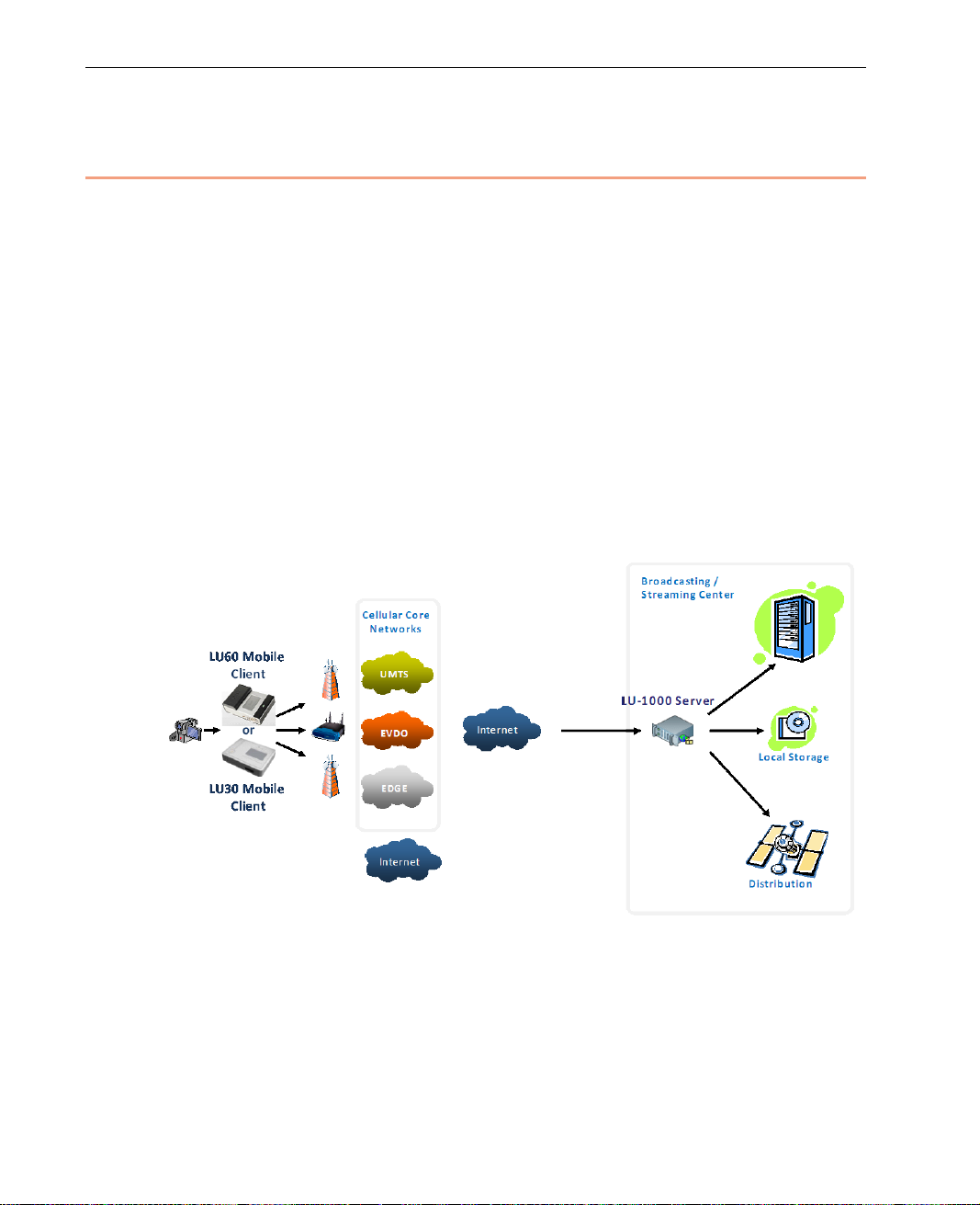
The LU Live Video Uplink unit simultaneously aggregates a numb er of
networking infrastructure s ( cellular, Wi-Fi and so on) in order to stream live
audio and video from field locations to the LU-1000 central server, which is
usually located in a broadcasting center.
The LU-1000 server gathers the live video feed via a secure Internet
connection and is then able to supply this feed to the production suite, routing
table, website and such for furthe r pr o ce ssing.
The technology offers a viable alternative to traditional uplinks, both in terms
of video quality, as well as in pricing, immediacy of service, av ailability and
portability.
An example of a typical deployment of the LU (client) and LU-1000 (server) is
shown below:
Figure 1: Solution Architecture
14
Page 15

Wireless Connectivity
The LU unit is designed to search for and connect to whichever cellular,
wireless or Ethernet (LAN) data infrastructures are available. The system has
several bui lt -in interfaces that are able to estab lish a connection to many
different networks simultaneously in order to over com e inherent bandwidth
limitations and offer robust transmissions. In addition, for areas where cellular
transmissions are problemati c, it is possible to use other available wired or
wireless Internet connections.
When the operator begin s u sing the LU unit by tapping Connect, the system
automatically searches for and conn ects to all the interfaces it detects in the
immediate area and then automatically analyzes and calibrates the system to
provide the best possible broadcast according to the Profile selecte d by the
camera operato r and the actual air bandwidth.
The LU system’s flexibility enables users to select different conf igurations for
certain situations where it may be necessary to manually reconfigure the
original setup. For example, when the required bandwidth for transmission
may not be sufficient or the video resolution may need to be change d from
broadcast to broadcast.
Overview
When broadcasting over cellular or wireless infrastructures, the physical
location of the LU unit should be taken into consideration. The LU contains a
proprietary set of interna l a ntennas, which enables operation even in typical
Dead Cellular Zones. Even so, there may still be areas where the netw o r k
reception is poor and the unit must be moved in order to receive a better
signal. For exampl e, when broadcasting from a n indoor locatio n, it may be
necessary to move the unit closer to a window to get better reception.
NOTE
The LU live video uplink operates on wireless netwo r k s. You should
therefore refer to Appendix D, Safety and Maintenance on page 139
for safety instructions and fo r a description of other regulations
regarding the operation of the LU sy stem.
15
Page 16

LiveU Live Video Uplink System User Guide
LU as an Access Point
The LU can serve as an access point for enabling wireless device(s) in its
vicinity. For example, it can ena bl e the laptops near it in the field to connect
wirelessly to the Internet thr o ugh its cellular modems.
LU Device Types
LiveU provides the LU60/LU70 family of products for professional broadcast
applications. These products have a proprietary internal antenna arr ay that
extends cellular range, extends cellular dead zones into live zones and
provides a cost effective integrate d r o aming support option. The LU60/LU70
family supports up to 1080 full HD video.
The LU60/LU70 devices may be provided with one of the following video input
options:
• SDI Video + DV, or
• HDMI + Analog Composite + DV
16
Page 17

What’s in the Box?
The following describes the components provide d in the box for the LU60/LU70
family of devices.
LU60/LU70 Hardware Components
The LU60/LU70 Live Video U plink system consists of the follow ing
components:
• The LU60/LU70 Mobile field unit. Two LU60/LU70 configurations are
available:
SDI + DV (FireWir e 1394) V ideo IN
HDMI + A n alog (Co mponent, Composite and S-Video) + DV (FireWire
1394) Video IN.
The relevant cables are provided for each. HDMI cable BIDs are required in
order to ensure compatibility with FCC standards. If your kit does not
include these, then you may request them from LiveU. They will then be
provided free of charge.
Overview
• Two FireWire cables: A 4-pin to 6-pin connection and a 6-pin to 6-pin
connection
• One internal battery
• A dedicated power supply that connects to any standard 110VAC / 220VAC
power source
• The custom LU60/LU70 backpack
NOTE
Additional battery power is available as optional accessori es.
17
Page 18

LiveU Live Video Uplink System User Guide
Blank page for double-sided printing
18
Page 19
2
Page
Page
Page
Page
Page
Getting Started
This chapter describes how to get started using the LU, including powering on,
connecting the camera, connecting to the LU-1000 and broa dcasting (playing).
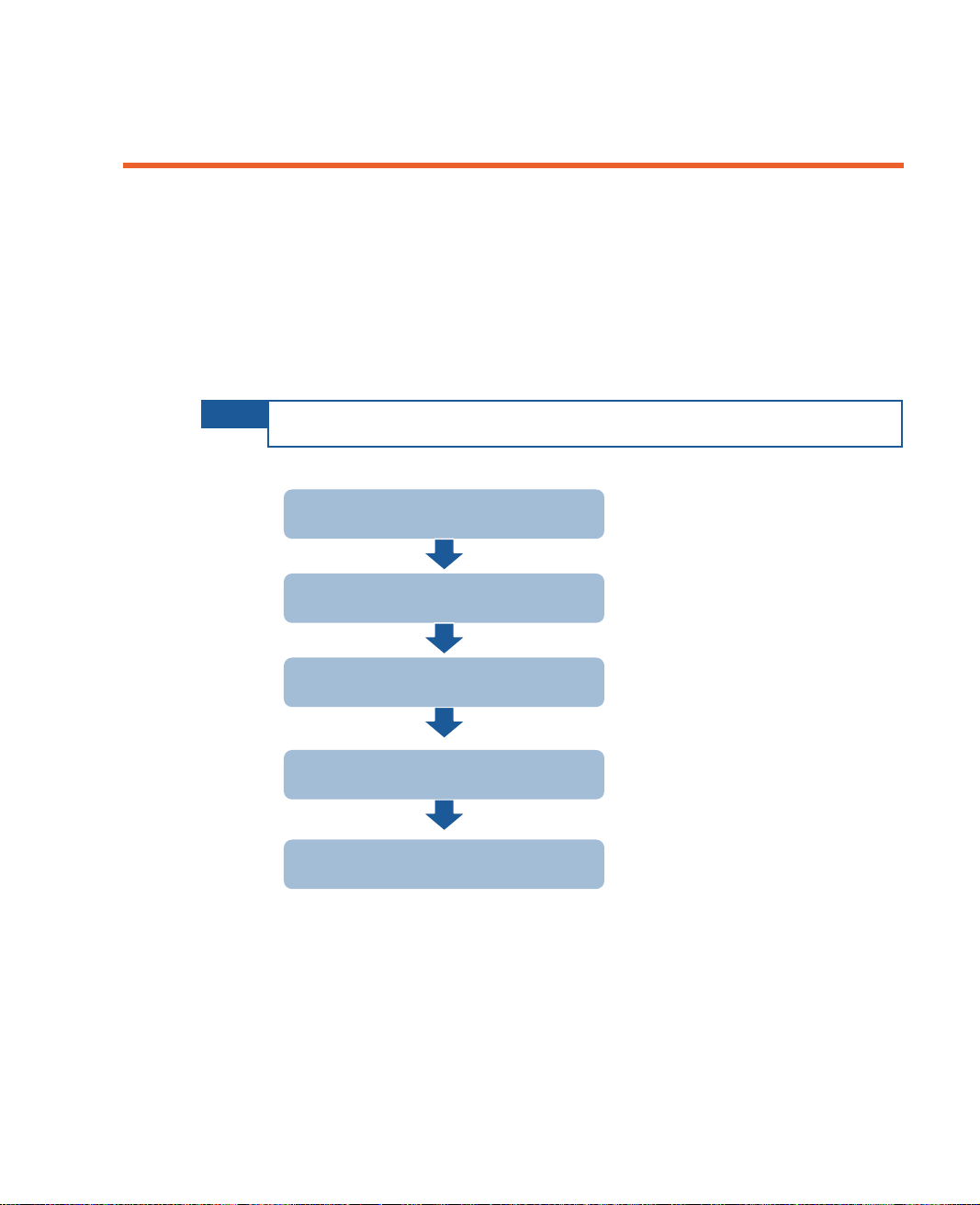
The following is an overview of the workflow described in this chapter.
NOTE
You may connect non-DV cameras to the LU before turning on the LU.
Step 1
Step 2
Step 3
Step 4
Step 5
If required, you may refer to Appendix B, LU Backpack on page 125 for
instructions on connecting and using the LU backpack.
Turning on the LU Device
Connecting the Video Camera
Connecting to the LU-1000
Playing
The Next Step
20
23
26
30
30
19
Page 20
LiveU Live Video Uplink System User Guide
for a description
Step 1, Turning On the LU Device
The following describes the procedure for turning on the LU60/LU70 family of
devices.
LU60/LU70 – Turning On the Device
The LU60/LU70 device is provided by LiveU with a char ged battery already
inserted.
NOTE
IMPORTANT
If required, you may refer to Changing the LU60/LU70 Battery section
on page 122 for a description of ho w to replace the battery or to the
Charging the LU60/LU70 Battery section on page 121
on how to charge the battery.
For DV cameras, it is recommended to first power on the
LU60/LU70 as described below, and then to connect the
camera. SDI, H DMI or Analo g c ameras can be connected
either before or after powering on the LU60/LU70.You may
refer to Connecting the Camera section on page 129, for
instructions on connectin g the camera.
For DV cameras, it is recommended to first power off the DV
camera, to connect the camera to the LU60/LU70 and then to
power on the camera. SDI, HDMI or Analog cameras can be
powered on either before or after being connected to the
LU60/LU70.
These instructions are also provided in the appropriate place in
the procedures that follow.
20
Page 21
Getting Started
Figure 3: PC IN Connection
► To turn on the LU60/LU70 unit:
NOTE
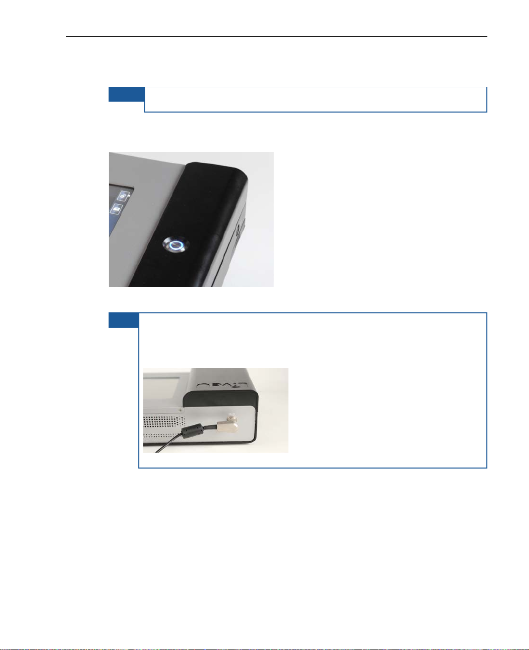
Do not connect a DV camera before po wering up the LU60/LU70.
Press and hold the power switch for appr o x imately two seconds until it lights
up.
Figure 2: P ower Switch On
TIP It is good practice to keep the unit plugged into a power outlet when it
is not in use in order to keep it charged and ready for oper ation.
Make sure that the DC IN (power ) co nn ecto r is connected in the
direction shown below:
The video camera can now be connected, as described in the Step 2,
Connecting the Video Camera sect ion o n page 23.
21
Page 22
LiveU Live Video Uplink System User Guide
Main User Window
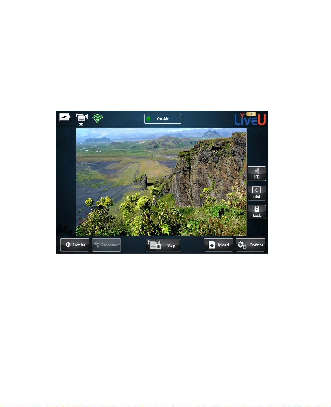
After a boot-up period, the touch-screen becomes active, and the user
interface appears, as shown below.
If the camera has been connected, powered on and then automatically
detected by the LU, a preview of the video f e ed i s automatically displayed in
the center of the main window, as shown below:
Figure 4: LU Main User Interface – With Camera
22
Page 23
Getting Started
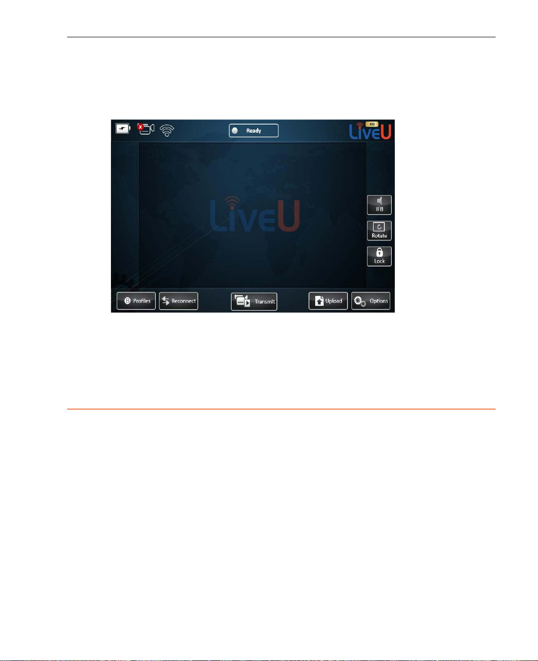
If the camera is not connected or setup properly, then the center of the main
window appears as f ollows. You may refer to Step 2, Connecting the Video
Camera on page 23, for i n str u ctions on connecting the video camera.
Figure 5: LU Main User Interface – Without Camera
A full description of the user interfa ce is provided in Chapter 3, L U User
Interface on page 33.
Step 2, Connec tin g the Video Camera
The procedure for connecting a video camera to a LU live video uplink unit is
simple.
Only one camera can be connected dire ctly to the LU unit at any one time. It is
possible to connect devices that act as a hub for cameras using FireWire to the
LU unit. Such devices are sometime s called Quad. However, even if more than
one camera is connected in this manner, only one feed from one camera at a
time is recognized and transmitted.
The following describes the procedur e f o r connecting a camera to the
LU60/LU70.
23
Page 24
LiveU Live Video Uplink System User Guide
For an HDMI camera, HDMI cable BIDs are required in order
LU60/LU70 – Connecting the Camera
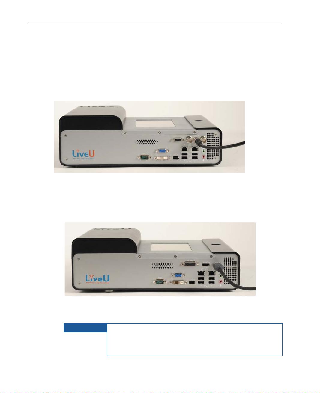
Different models of the LU60/LU70 are provided, each with the ability to
connect to different cameras. All models connect to DV (FireWire 1394)
cameras. The following LU60/LU70 unit connection options are available:
SDI + DV (FireWire 1394)
Figure 6: LU60/LU70 with SDI Camera Connection
For an SDI camera, only use the middle SDI co nnector.
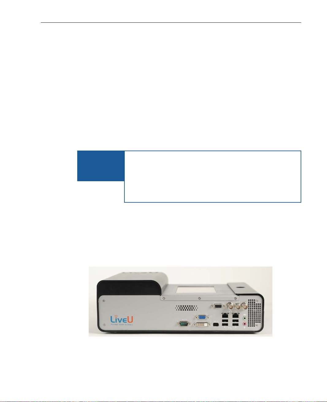
• HDMI + Analog (Component, Composite and S-Video) + DV (FireWi re
1394)
Figure 7: LU60/LU70 with DV, HDMI and Analog Camera Connection
For an HDMI camera, only use the HDMI IN connector.
IMPORTANT
to ensure compatibility with FCC standards. If your kit does
not include these, then you may request them from LiveU.
They will then be provided free of char ge .
24
Page 25
Getting Started
NOTE FOR DV
► To connect the camera:
1 For DV cameras, it is recommended to f irst power up the LU, and only then
to connect the camera to the LU.
An SDI, HDMI or Analog camera can be connected either before or after
turning on the LU.
2 For a DV (FireWire) camera, check that the camera is turned off and NOT
connected to any external power supply. SDI, HDMI or Analog cameras can
be powered on either before or after being connected to the LU.
3 Appropriate cables are provided for each type of c amera. Conne ct one end
of the appropriate camera’s cable to the relevant port on the video
camera.
IMPORTANT
In order to avoid permanen t d amage to a Fire Wire/DV
camera and the LU Live video uplink unit, you must only
(FIREWIRE)
use the LiveU provided FireWire/DV (1394E) cables!
CAMERAS
LiveU provides two types of FireWire/DV (1394E) cables:
one type connects 4 pins to 6 pins, wher e th e power is
connected, and the other type conne cts 6 pins to 6 pins.
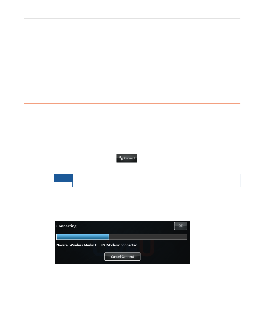
4 Connect the other end of the cable to the appropriate port (DV IN, SDI IN,
HDMI IN or A/V Analog) on the LU Video Uplink unit, according to the type
of camera, as follows:
For a DV camera, connect to the DV IN connector.
For an SDI camera, connect to the middle SDI connector .
For an HDM I camera, connect to the HDMI IN connector.
Figure 8: LU Video Uplink Unit Connections
25
Page 26
LiveU Live Video Uplink System User Guide
5 For DV cameras, after the camera is attache d to the unit, you can connect
an external power supply to the camer a, if ne eded. Then, turn the camera
on.
6 The camera video is automatically displayed on the unit’s screen, if the
camera is on and properly configured. The screen on the unit’s interface
should display the scene that the camer a is capturing.
Step 3, Connecting to the LU-1000
In order to stream video using the LU Live Video Uplink system, it is necessary
to connect the unit via the Internet to the LU-1000 server usin g o n e o r more
wireless networks. The LU-1000 server is usually located at the br o adcasting
center.
► To connect to the LU-1000:
• Tap the Connect button .
The Connect button on the display changes to ReConnect.
NOTE
The LU unit automatically searches for and detects the interfaces (ce llular
modems, Wi-Fi, LAN and so on) that are available on the unit and connects
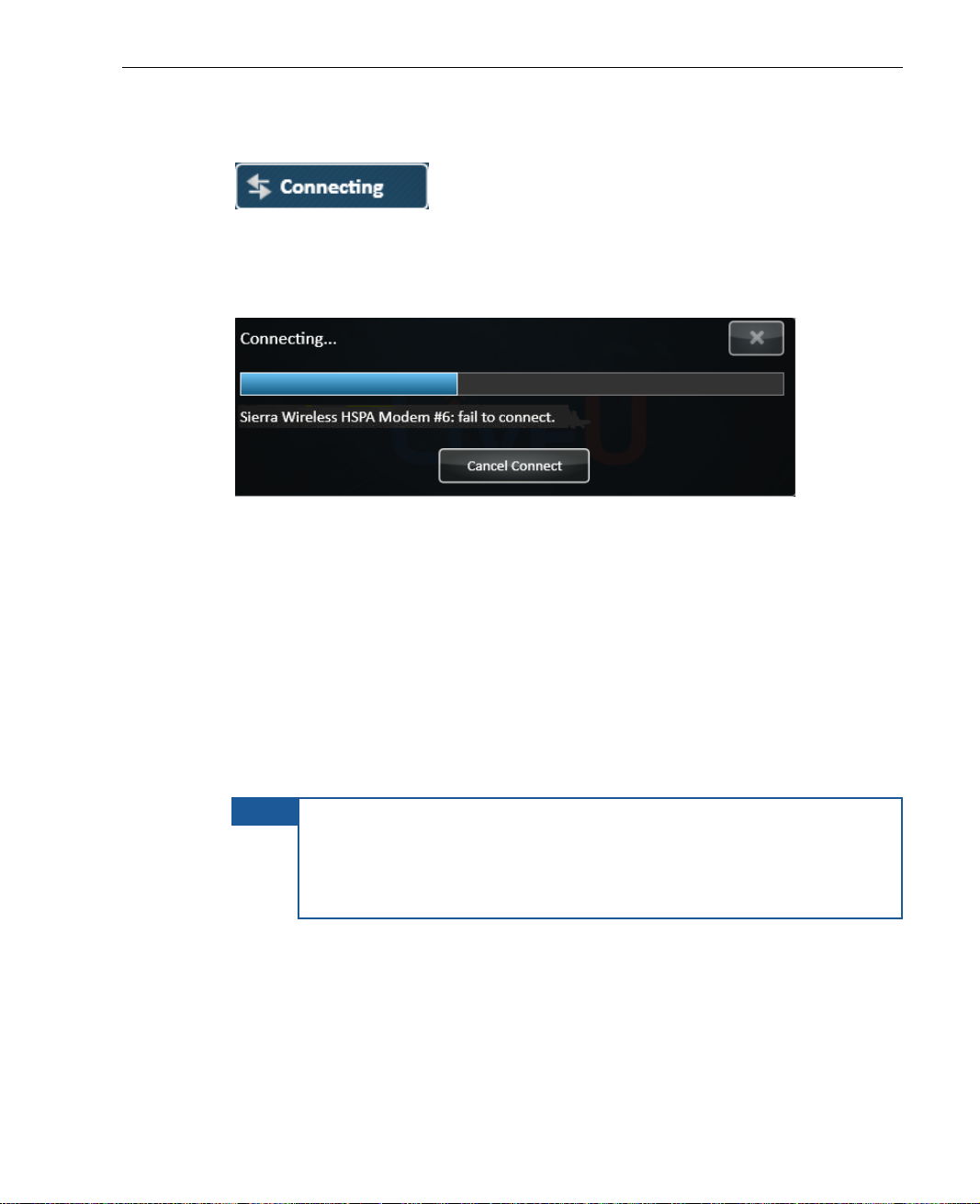
to each one.
As each interface is connected the fo llowing is displayed for each:
Figure 9: Connecting to an Interface
This process may take up to five minu tes to co mplete.
26
Page 27
Getting Started
The Connecting status indicator is displayed, as shown below:
Figure 10: Connecting Status Indicator
Even though the LU can operate withou t all interfaces, it retries connecting
a number of times before giving up and displaying the following message:
Figure 11: Interface Connection Failed
After the modems are connected, the system carries out network -related
tests and the application automatically calibrates the available b andwidth
efficiency and delay for each of the inte r faces. It also determines the best
parameters for ensuring that the system fu n ctions at maximum efficiency.
After this calibration, the LU application is able to calculate the ov erall
system efficiency, total effe ctive bitrate and delay.
After the system has finished this cal ibration, the LU unit automat ically
sets the video bitrate to the value reco m mended by the system according
to combination of selected Profile and Resolution.
NOTE
If the connection process results in a low v ideo rate, tap
ReConnect. The system then recalibrates itself. If the problem
continues, then you can change the video bit rate manually using
the Options button Configuration button Media button, as
described in Chapter 6, Configuration and Settings on page 73.
27
Page 28
LiveU Live Video Uplink System User Guide
Click here to
the
settings of the
Interview Profile
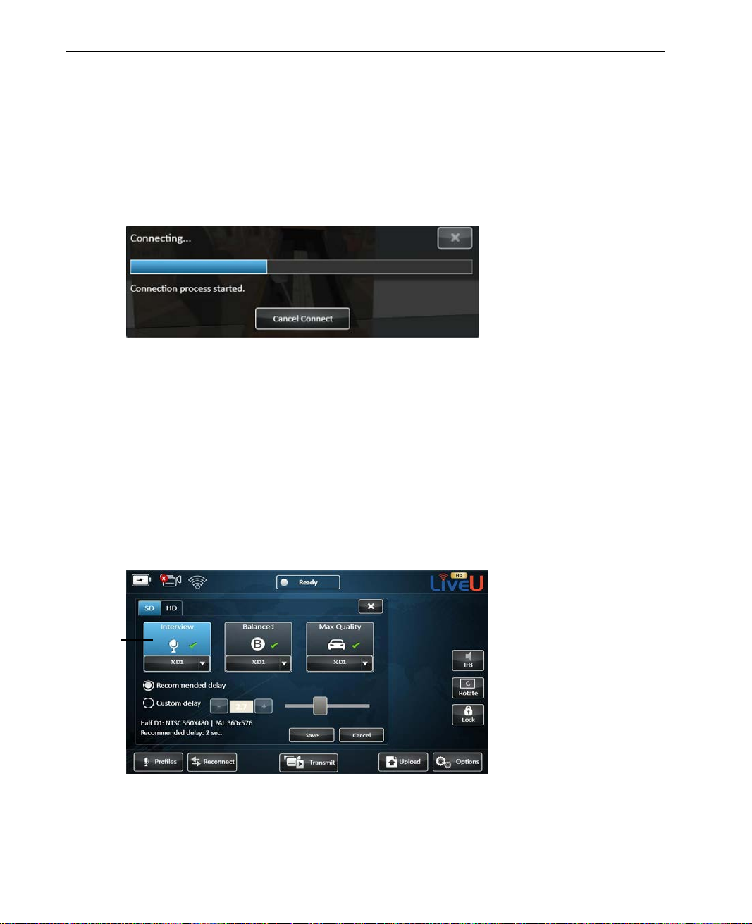
Connecting – Transmission Test
In order to accurately calculate and grade the modems and their broadcasting
efficiency, the LU automatically transmits a LiveU pre-stored vi deo str eam.
During transmission, the following window appears showing the transmitted
video:
Figure 12: Connecting – Transmissio n Te st
The process finishes when all the av ailable interfaces have been conne cte d and
the LU unit has finished analyzing the connection and calibrating the system.
This is an internal process that runs automatically.
display
After Connection
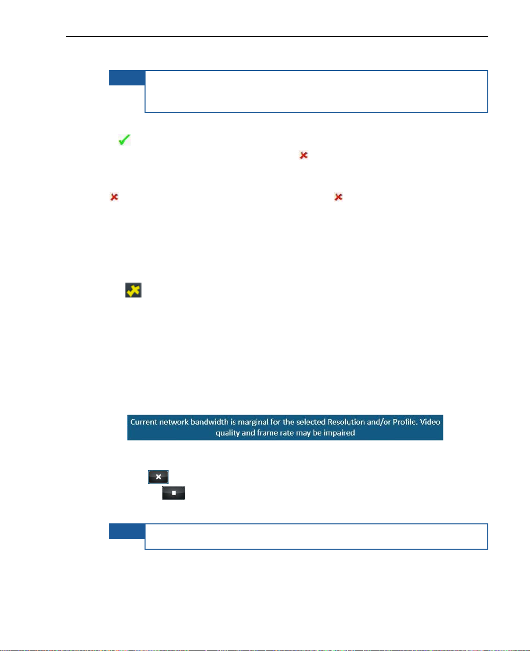
After the LU has finished the connection pr ocess, the Status indicator at th e
top of the screen changes from Offline to Ready and the calibration results
can be displayed by selecting the Profile button, as shown below :
Figure 13: Profile Parameters
28
Page 29
Getting Started
NOTE
During installation, you can choose SD or HD configuration. For HD
configuration, the LU is installed with HD, without inserting a camera.
Only LU products with HD support display the HD tab, shown a bove.
The Profiles and Resolutions that ar e available for selection are disp layed with
a
(green). The Resolutions that are not available for selection w ith the
currently selected Profile appear with a
(red). If you would like to see the
reason that a Resolution is not available, then simply tap on it to display an
explanation window. If all the resolutions of a Profile are not av ailable (hav e a
(red)), then the Profile button itself has an (red).
The end-to-end delay for the selected Profile is also displaye d, as shown
above.
When the Interview Profile is selected, the Recommended (Optimal) delay is
displayed, as shown above.
An
icon appears on a Profile or Resolution button as a warning that
minimal interfaces are used, which m a y result in degrad ed video quality. It is
not mandatory, but if you want to impro ve the video quality, you can select a
different Resolution or select a diff erent Profile, if you want to use the s ame
Resolution.
If the currently selected resolution is not supported and you tap the Play
button, then:
• The following mes sage is d isplayed:
Figure 14: Unsupported Resolution
• Tap to close this message window and then tap the Stop
button
.
• Tap the Profile button to select another reso lution.
NOTE
The system will allow you to transmit, but quality cannot be ensur ed.
29
Page 30
LiveU Live Video Uplink System User Guide
Step 4, Playing
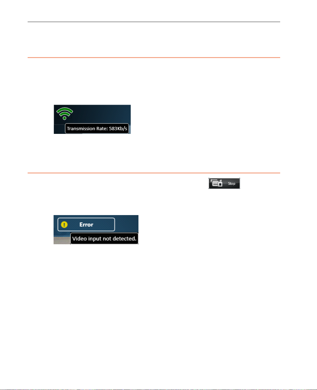
Tap Transmit to start broadcasting live streaming video to the broadcasting
center.
You can tap the Transmission Strength indicator to display the number o f Kb/s
transmitted and received, as shown be low:
Figure 15: Transmission Strength
Step 5, The Next Step
After you have finished playing, you can tap the Stop button.
If you turn off the camera during playing, then an Error status appears. If you
tap the Error status indicator th en a message is displayed, as shown below:
Figure 16: Camera Disconnected or Off
If the camera is disconnected during transmission, then after the camera is
reconnected, trans missio n will automatically continue. You do not need to
reestablish the connection. T o start transmitting, simply tap Transmit.
30
Page 31
Checking Inter f ace Quality
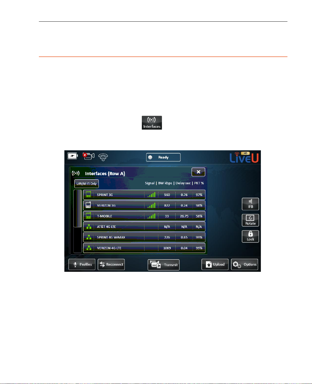
It is not mandatory, but you may want to check the quality of your interfaces
before starting transm ission, meaning before pressing the Transmit button.
You may also decide to check the quality of th e interfaces after a long time h as
passed since calibration was performed (meanin g since the Connect button
was pressed) or immediately aft er transmission conditions have changed (for
example, from stationary to driving).
Getting Started
Tap the Interfaces button
Wi-Fi, LAN and so on) of the LU. The I n terface table shows a list of all of the
interfaces to which the LU unit is able to connect, as shown below:
Figure 17: Interface Table
to view the interfaces (cellular modems,
31
Page 32
LiveU Live Video Uplink System User Guide
Under certain conditions, it may be necessary to change configu rations
networks are connected and manually change configurations using the
do not display a let ter
Each connected interface appears with a (Green) icon. This list changes
dynamically to reflect the curr en t situation. You may refer to the Interfaces
section on page 75 for more information.
NOTE
for a better quality video transm ission. It is possible to view which
Options button Configuration button Media button. For more
information, refer to Chapter 7, Configuration and Settings on
page 73.
NOTE
The LU60/LU70 product s th at support dual SIM are pr o vided with
modules. A module has two rows of SIM cards: A and B. Two SIM
cards of each type are on the module, one on each row. Only one row
of SIM cards is used at a time. This window indicates the letter (A or
B) of the row that is used, as follows:
Devices that only have a single row of SIM cards
(A or B) in this window.
You may refer to the Utilities section on page 98 for a description of how to
select which row of SIM cards is used.
32
Page 33

3
LU User Interface
This chapter describes the main LU window and the options that it provides.
This chapter contains the following sections:
• LU Touch-screen Interface, page 34
• Video Feed, page 35
• Camera Connectivity Icon, page 36
• Battery Indicator Icon, page 37
• Transmission Quality, page 38
• IFB Indicator, page 39
• Status Indicator, page 41
• Rotate Screen, page 42
• Unlock/Lock Button, page 42
• Options Button, page 43
• Upload Button, page 43
• Connect/Reconnect Button, page 43
• Transmit Button, page 44
• Profiles, page 45
• Platform and Unit Name, page 45
33
Page 34
LiveU Live Video Uplink System User Guide
Signal
Strength
Video Fee d
Transmit
File Uploa d
Setup
Options
Camera
Connectivity
Platform and Unit
Battery
Indicator
Status Indicator
Profile In dicator
and
Configuration
Connecting for
Unlock/Lock
Button
Rotate Screen
IFB
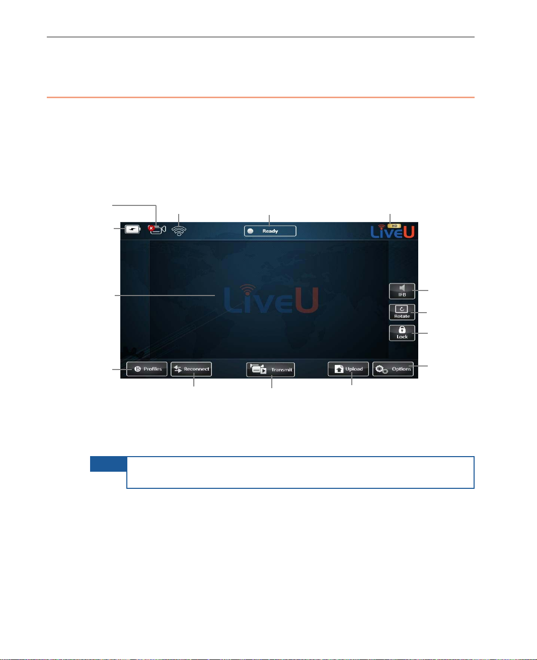
LU Touch-screen Inter fa c e
The Live Video Uplink User unit’s user interface is an LCD touch-screen. This
main window automatically displays when the unit is ready.
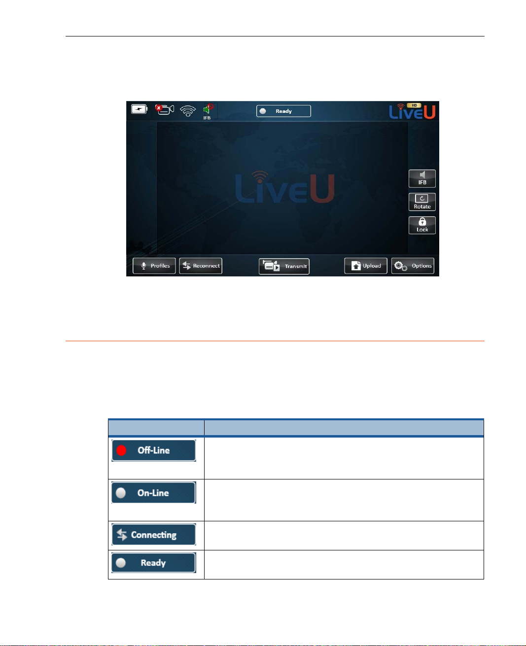
This touch-screen shows the video feed in its center and provides various
buttons and indicators for co ntrolling the unit and its broadcast.
Broadcast
Figure 18: LU Live Video Uplink User Interfa ce
The following desc ribes the various element s in the m a in window .
NOTE
It is possible to add a USB-enabled keyboar d and mo use to the LU
unit. The USB attaches to the USB out let on the side of the unit.
34
Page 35
Video Feed
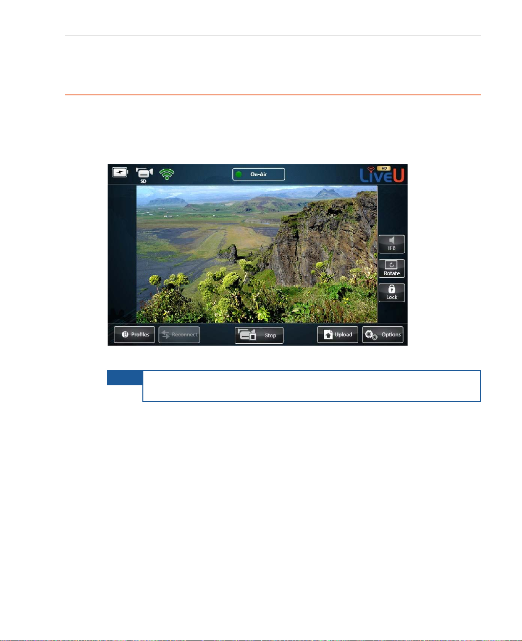
The center of the main window autom ati cally shows a preview of the video
feed after the camera is connected, turned on. The video feed is displ ayed a
few seconds after the camera is connected and automatically detecte d by the
LU.
LU User Interface
Figure 19: Video Feed
NOTE
You may refer to the Main User Window section on page 22 for a picture of this
area, before the camera is connected/ detected.
The video is only transmitting after y o u tap the Play button and the
On-Air status indicator is displayed at the top of the window.
35
Page 36
LiveU Live Video Uplink System User Guide
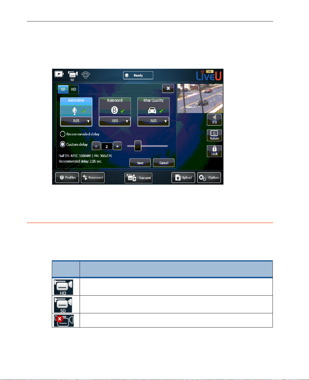
After the camera is connected, the video feed is always showing. Wh en y o u
are using the configuration w indows, it appears in the top right corner o f the
window, as shown below:
Figure 20: Video Feed is Always Displayed
Camera Connectivity Icon
The Camera connectivity indicator sho ws the current status of the camera
connection, as follows:
Table 1: Camera Connectivity Indicator Icon
Status
Icon
Description
Indicates that an HD camera is connected. This feature only
appears for LU60/LU70 devices that support HD.
Indicates that a standard camera is connected.
Indicates that no camera is connected.
36
Page 37
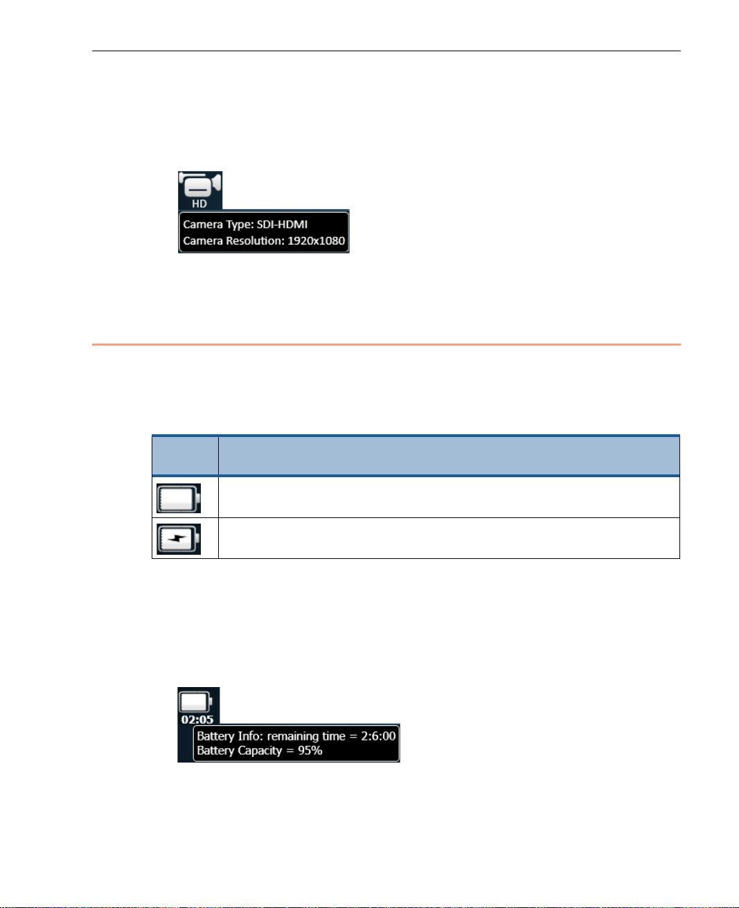
► To display information about the connected camera:
battery is fully charged, partially charged or empty.
• Tap on the Camera Connectivity icon to display a tool tip of information.
The following tool tip shows the camera’s type and resolution:
Figure 21: Camera Tool Tip
Battery Indicator Icon
The Battery indicator shows the battery’s current status. Tapping the battery
indicator, displays informati o n about the battery charge status, as fo llows:
Table 2: Battery Indicator Icon
LU User Interface
Status
Icon
Description
LU is running off internal battery. The indicato r shows that the
The unit is connected to an AC charger, and the battery is currently
being charged.
► To display a description of the batteries status:
• Tap on the Battery icon to display a tool tip of information. The follo wing
tool tip can be displayed while the battery is being used (and is not being
charged). It shows how much lon ger the battery will last and the
percentage of the current charge.
Figure 22: Battery Status Tool Tip – Time Remaining
37
Page 38
LiveU Live Video Uplink System User Guide
for a description of
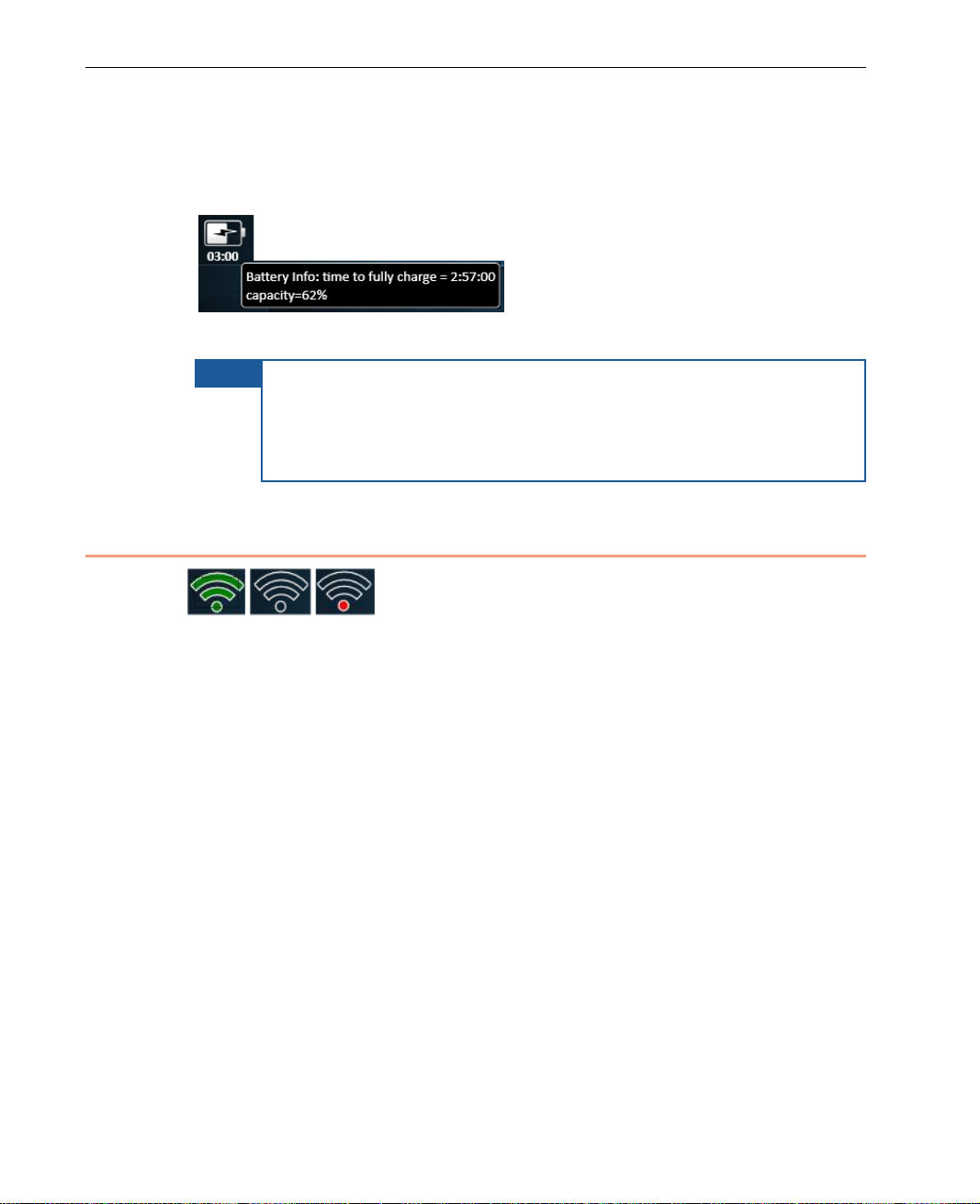
A tool tip can be displayed while the b atter y is being charged. It shows the
percentage of the battery’s current charge and the amount of time
remaining until the battery will be f ully charged.
Figure 23: Battery Sta tus Tool Tip
NOTE
It is also possible to see the battery charge o n the battery itself by
opening the battery compartment. Th ere is a small LCD indicator
that shows up to five bars. You may r efer to Checking the
LU60/LU70 Battery Char ge se ction on page 120
the battery charge indicator in the battery compartment.
Transmission Quality
Figure 24: Transmission Quality
This indi cator shows the quality of the transmission between the LU and the
LU-1000 server. When you hover over it, a tool tip is displayed show ing the
average transferred bitrate dur ing the last four seconds.
This indicator changes as fo llows:
• Gray – Not connected
• Three bars and Green – Good connection
• An interim status (for example two green bars) reflects the overall status
of all the interfaces.
This indicator is updated every few seconds. For example, transmission quality
could be 1,245 kbps.
38
Page 39
LU User Interface
hat does not enable the operator to
IFB Indicator
IFB (Interrupted Feedback) feature enables an LU operator to listen to an audio
channel received from an IFB server using an earphone, even while
broadcasting. Typically, t his type of communication is used to receive verbal
instructions or information about events.
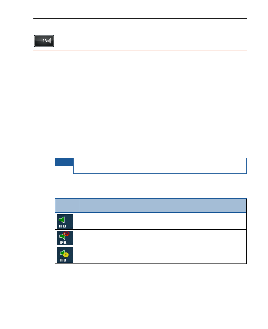
The IFB Indicator icon shows the statu s of the IFB feature, meaning wheth er it
is active, muted or has an error. Multiple channels can be provided to which
the LU operator can listen. When the LU device is first started, it only displays
one IFB channel called the Default Chan nel, a s shown below. After the Start
button is tapped and the LU is connected to the LU-1000, the LU connects to
the IFB server and retrieves a list of al l the available IFB channels. These
channels are then displayed for your selection. In this window , you select
which channel is played on the LU. Only one channel can be selected (listened
to) at a time. Multiple LUs can connect to a s ingle IFB server and listen to the
same channel.
NOTE
This is a si ngle dire ctional channel t
respond in anyway.
The following shows the IFB icons that appear on the screen:
Table 3: IFB Indicators
Status
Icon
Description
The IFB audio channel is playing.
The IFB audio channel is muted. The IFB channel can be muted
using the Mute button, as desc ribed below.
A problem exists on the IFB channel. T ap this tool for more
information.
39
Page 40
LiveU Live Video Uplink System User Guide
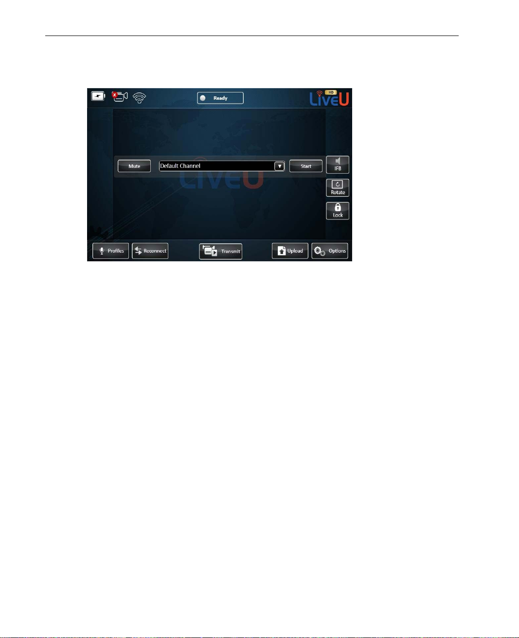
Tapping the IFB button displays the following win dow:
Figure 25: IFB Configuration Window
► To configure the IFB channel:
1 Select one of the IFB channels provided by th e IFB server from the
displayed list.
2 Click the Start button to start playing the selected channel.
40
Page 41
LU User Interface
3 By default, the IFB is not muted. You can select the Mute (or Unmute)
button. You can click the Stop but to n to close the IFB channel.
Figure 26: IFB Channel Open
Status Indicator
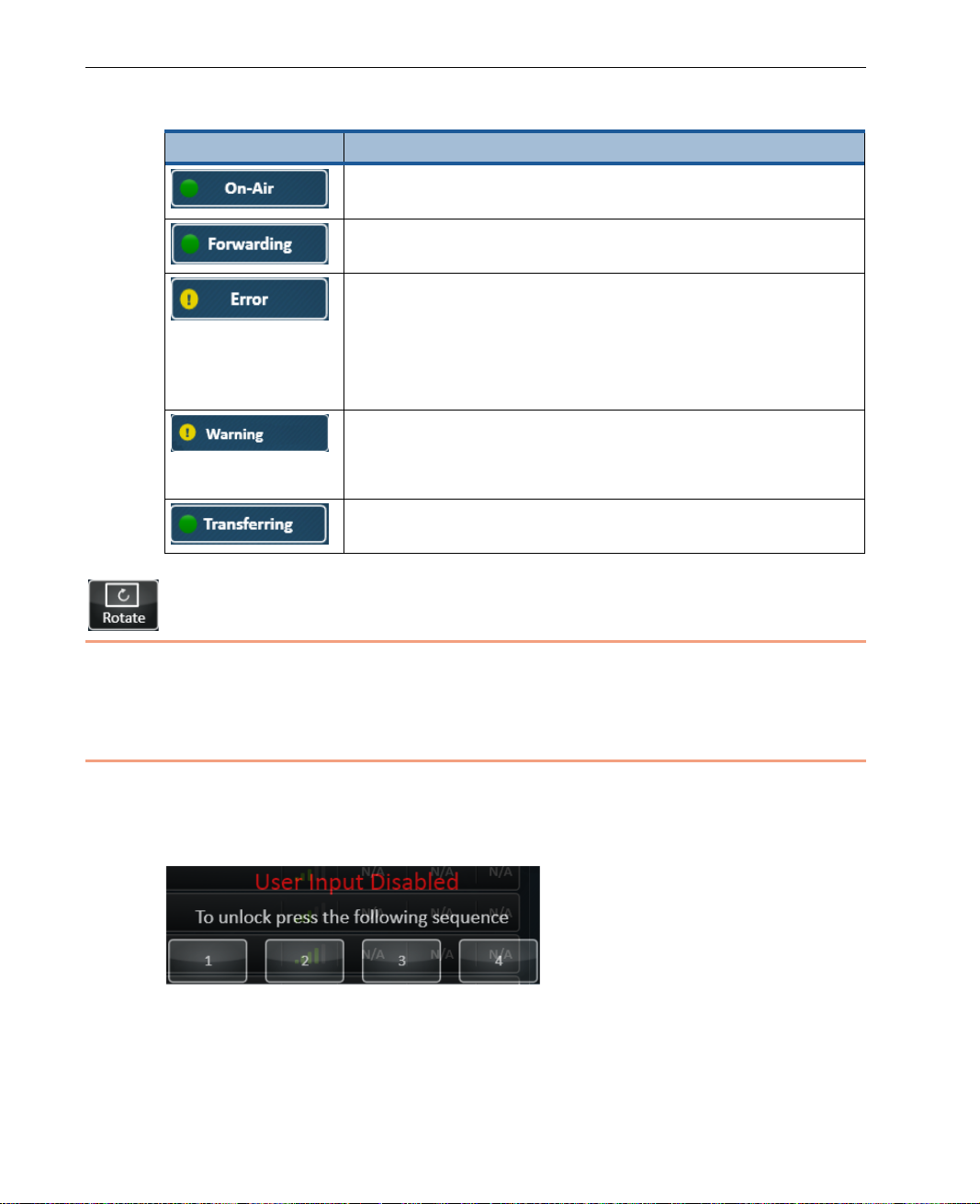
The status icon at the top of the window provides information about the
connection and transmission status of the LU. The color of the indicator and
the text indicate the unit’s status, as follows:
Table 4: Status Icons
Status Icon Description
Off (red light). Appears before the Connect button is
tapped), which means that the system is not yet
connected to any interface.
On-Line (white light). Appears when the modems are
dialed successfully fo r the purpose of opening a
non-video channel.
Connecting (opposing arrows). Appears during the
connection process.
Ready (white light ). Appears after connection is
successful, and before the Play button is tapped.
41
Page 42
LiveU Live Video Uplink System User Guide
Status Icon Description
On-Air (green light). Appears wh en the system is
connected and video is being transmitted correctly.
Forwarding (green light) . Appears when a stored
session is being forwarded.
Error (yellow light). Appears when an error occurs. You
can tap to display an error message, such as the
following:
• Error: LU-1000 not responding
•
Error: Video input not detecte d
Warning (yellow light).
• Warning: X packet(s) lost
•
Warning: X missing interface(s)
Transferring (green light). FTP-mode is active. Files are
being transferred.
Rotate Screen
Each tap of this button rotates the screen display 180 degrees.
Unlock/Lock Button
Tap the Lock button to lock the touch screen button s so that they are not
tapped by accident. The following window is then displayed in which you must
tap the numbers 1, 2, 3 and 4 in sequence in or der to unlock the touch screen.
Figure 27: Locking and Unlocking the Touch-screen
42
Page 43
LU User Interface
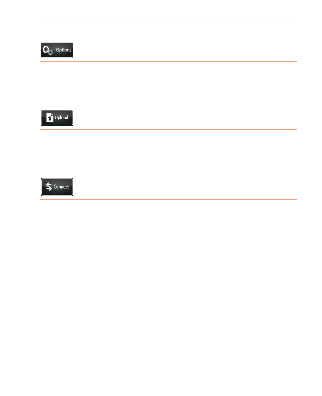
Options Button
This button displays informati o n about the broadcasting interfaces,
configuration settings and channels. It also enables you to access re m o te
support and to restart or power down the u nit. A full description of the options
provided by this button is in Chapter 7, Configuration and Settings on page 73.
Upload Button
This button enables you to store pr erecorded files, transfer prerecorded files or
simultaneously store and fo r ward the prerecorded files to the LU-10 00 server.
This option can also be used to tran sf er any type of file to the LU-1000 server,
such as a document.
Connect/Reconnect Button
Connect Button
The LU detects all available interfaces immediately when the unit boo ts. These
interfaces can be seen in the Inter face window, but the BW and Delay of each
interface are only shown after the in te r faces are connected by tapping the
Connect button.
When the Connect button is tapped, the LU attempts to connect to all the
interfaces (modems, LAN and so on). Then the appli cation au tomatically
calibrates the available bandwidth and determines the parameter s according to
the current Profile and Resolution s elections to ensure that the system
functions at maximum efficiency. T he calibration al so identi fies wh ich
combinations of Profiles and Resolutions are now possible, and what is the
minimal delay than can be manually configure d in the Interview Profile.
43
Page 44
LiveU Live Video Uplink System User Guide
Reconnect Bu tto n
After the Connect button is tapped and a connection has been e stablished,
the button’s name changes on the display to Reconnect. This means that the
LU is connected to the LU-1000 se rver.
When the Reconnect button is tapped, the application automatically attem pts
to reconnect to all available interfaces in order to achieve better connectio n
performance.
The following describes the reasons for tapping the reconnecting:
• If you feel that network conditions are not o ptimal. You can check the
following and then decide to reconnect:
If you tap the Interface button and see a low BW kbps and/or high
Delay sec for each or some of the interface rows.
If you tap the Profiles button and see an
Profile button or on the desired Resolution button indicating that it is
not availa ble.
(red) on the desired
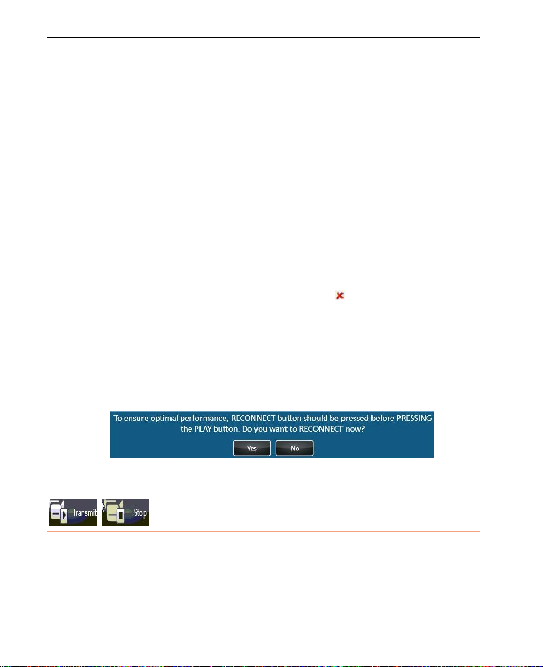
• The following message is displayed from time to time in order to ensure
optimal performance. It is recommen ded to tap the Yes button so that the
unit will reconnect to its interfaces and re calibrate the optimal connection
parameters. B roadcastin g an d file transfer will automatically continue after
reconnection.
Figure 28: Reconnection Message
Transmit Button
This button becomes active after the unit is connected to the LU-1000 and the
unit is ready to broadcast or send f iles. Tap the Transmit button to start
broadcasting.
44
Page 45
LU User Interface
Profiles
This button indicat e s the Profile according to which the LU is currently
operating, as follows:
Interview
Balanced
Max Quality
You can tap this button to display information about the selected Profile and to
select a different Profile or reconfigure the settings of a Profile.
A full description about the Profiles provided for the LU and how to select them
is provided in the Profiles Window section on page 48.
Platform and Unit Name
Tap the LiveU logo to display the following window showing the
LU’s platform and unit name.
Figure 29: Platform and Unit Name
45
Page 46

LiveU Live Video Uplink System User Guide
Blank page for double-sided printing
46
Page 47

4
Successful Video
Transmission
This chapter describes some of the aspects on which successful transmission
of a high-qua lity audio/video stream depend, such as video resolution, targ et
resolution, bitrate, CODEC and so on.
This chapter contains the following sections:
• Overview, page 47
• Profiles Window, page 48
• Changing the Profile, page 50
Overview
• Changing a Profile’s Resolution, page 55
Successful transmission of a high-quality audio/vide o stream depends on a
number of elements, such as video resolution, target resolution, bitr ate,
CODEC and so on. The LU unit analyzes the cur r ent network conditions and
sets the optimum configuration auto matically. However, if conditions warrant,
it is possible to adjust several of thes e elements manually.
Target Audience
The target audience should be decided before starting transmission. In other
words, the camera operator should know what is being filmed and how it will
be broadcast from the studio. With this in mind, it is possible to select the
appropriate parameters to ensure the best broadcast.
47
Page 48

LiveU Live Video Uplink System User Guide
The main factors when deciding target resolution are the quality of the
broadcast and the delay. For example, if the event is a sporting event
(Olympics, a ball game and so on), then it is important to use the highest
bitrate available. If the b roadcast is an interview aft e r the game, the n a lower
bitrate is effective. If the broadc ast is for the Internet, it is not always
necessary to use a resolution greater than CIF or half D1.
Profiles Window
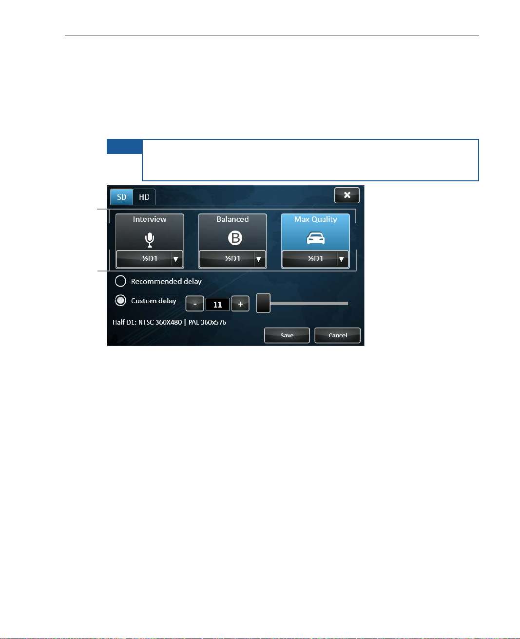
This Profiles button indicates the selected Profile, according to wh ich the LU is
currently operating, as follows:
Interview
Balanced
Max Quality
You can tap this button to display information about the selected Profile and to
select a different Profile or reconfigure the settings of any Profile.
48
Page 49
Successful Video Transmis s ion
Profiles
Resolution
selected for Profile
LU products that support High Definition (HD) automatically detect whether an
HD or a Standard (SD) camera is connected. For these devices,
SD option is automatically selected in the window below.
the HD or
In addition,
the preconfigured Profile (Interview, Balanced or Max Quantity) and Video
Resolution is automaticall y selected (such as Full D1 or Web HD).
NOTE
If the device detects that the interf ace quality is insufficient to suppor t
the selected Profile and Resolution, then the device does not transmit.
You can then select a different Profile and/or Resolution.
Figure 30: Profiles Window
The currently selected Profile appears highlighted. The top of the three big
buttons in the center of the window indicates the provided Profiles. The
selected Profile’s quality and overall video transmission latency are displayed
at the bottom left of the window.
The bottom of the three big Profile butto n s indicates the Resolution selected
for that Profile.
49
Page 50
LiveU Live Video Uplink System User Guide
Select one of
these Profile
buttons
Changing the Profile
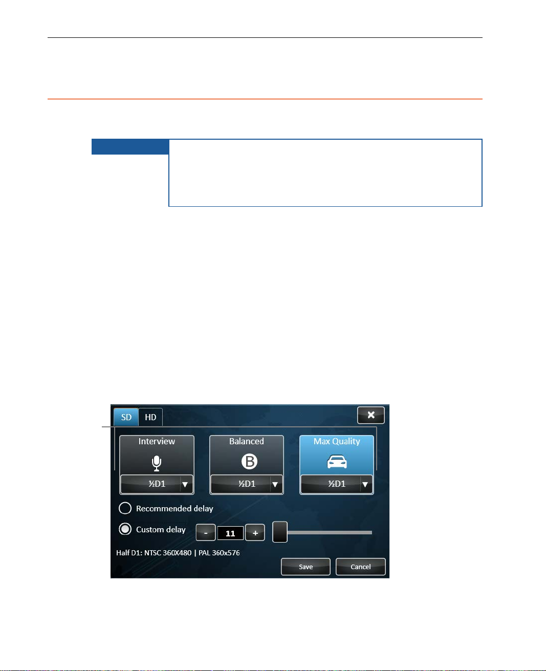
Changing the selected Profile changes the basic characteristics of the
broadcast (such as quality and/or delay).
IMPORTANT
Three Profiles are provided by the device, which are the same for both SD and
HD cameras. The currently selected Profile appears highlighted. Its name is
indicated at the top of the Prof ile but to n . The bottom of the window display s
the selected Profile’s quality and ov erall video transmission latency.
The preconfigured res olution for each Profile is automatically s elected.
Typically, there is no need to change it. If needed, you may ref er to the
Changing a Profile’s Resolution section on page 55 for a description of how to
change a Profile’s resolution.
There are limitations to when changes can be made. You
cannot select whether to enable/disable modems on the fly.
Profiles, Resolutions or Custom delay cannot be changed
during broadcast. In order to change the bitrate, it is
necessary to stop the transmission before making the change.
► To change the currently used Profile:
• Simply tap one of the Profile buttons: Interview, Balanced or Max
Quality, as shown below:
Figure 31: Profiles Window
50
Page 51
Successful Video Transmis s ion
Click here to
display the
settings of the
Interview Profile
Profile Descriptions
The following desc ribes the features and benefits of each Profile:
• Interview Profile, page 51
• Balanced Profile, page 52
• Max Quality Profile, page 54
Interview Profi l e
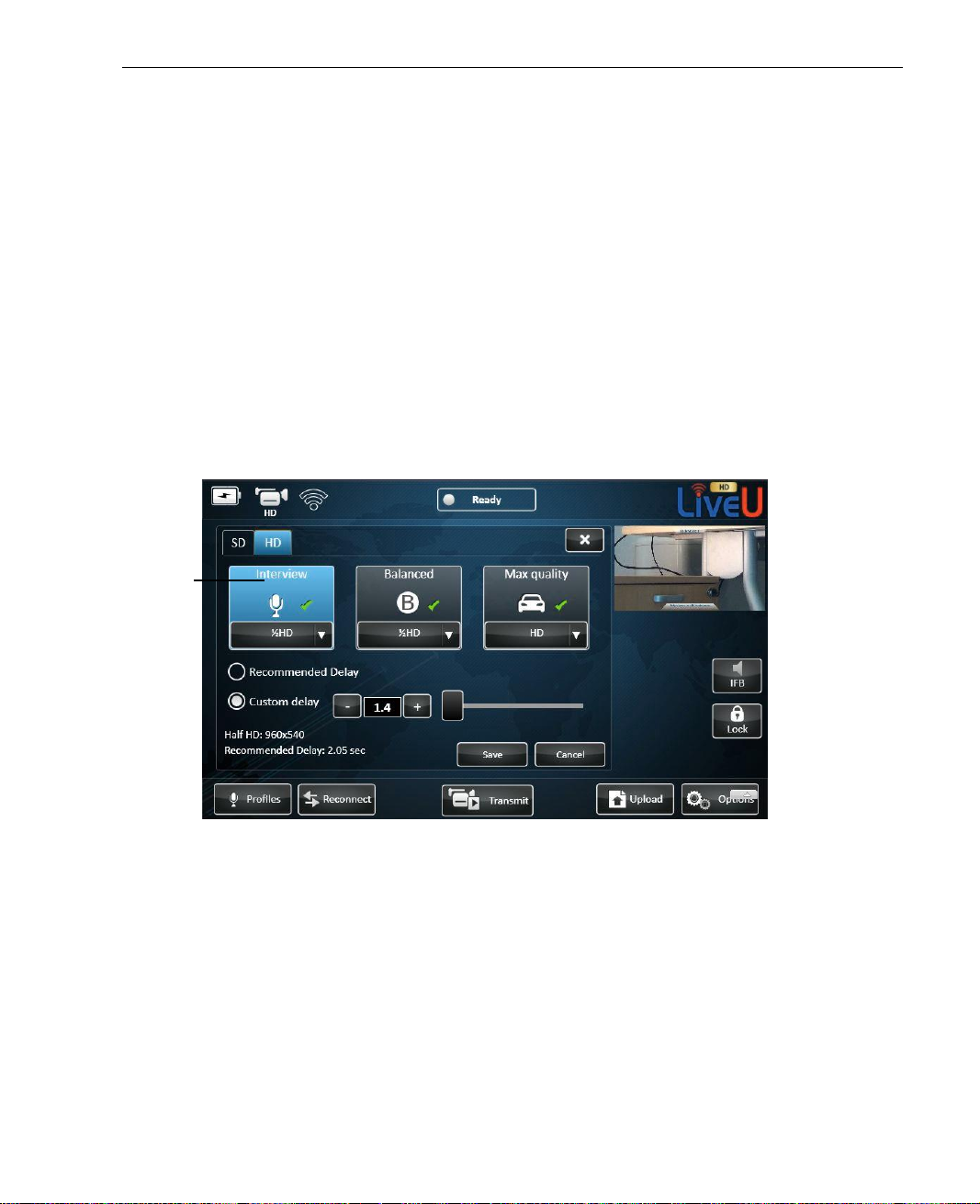
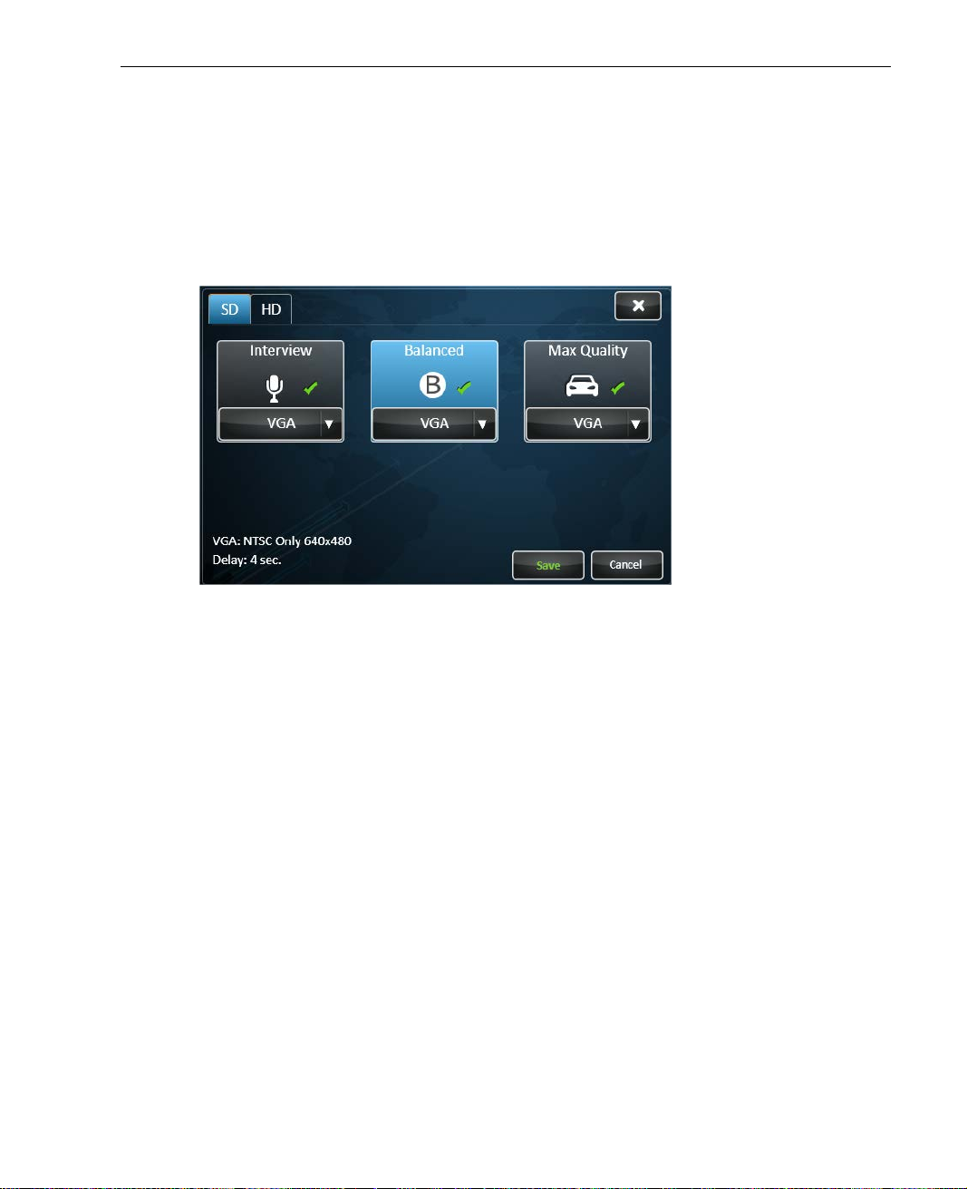
Select the Interview Profile when you need a short end-to-end delay. This
Profile provides the maximum quality within the restriction of the shortest
delay.
Figure 32: Interview Profile
51
Page 52
LiveU Live Video Uplink System User Guide
This mechanism reduces the Frames Per Second (FPS) to allow
. Once networks
NOTE
This Profile is more resilient to changes (errors) and adapts quickly to
bandwidth changes. It is designed not to freeze. However, the quality may
drop if networks condition s worsen abruptly.
IMPORTANT
The Interview Profile includes an automatic mechanism that
activates when the network conditions worsen significantly.
a clean image with sufficient quality rather than pixelization.
When this happen, the image may look jumpy
conditions impro ve, then the FPS will be automatically
increased as well.
Interview Profile Delay
Interview profile allows for the shortest delay, 1.35 – 5 seconds. The delay in
this Profile is automatically set by the system after calibration and depends on
the selected resolution. The R ec om m end ed del ay checkbox is automatically
selected to indicate that this Profile is using the automatically delay set by the
system after calibration.
You can manually set the delay and overr ide the system’s automatic
recommendation by checking the Custom delay checkbox. The system then
displays the upper and lower permitted delay limits according to the
performance of the Interfaces measured in the Calibration process during the
Connect phase. You can then type in or use the slider to specify the des ired
delay. Please note that reducing the delay below the syste m ’s r e commended
one may result in less video resiliency and/or image qua lity.
Generally, as a rule of thumb, the longer the delay, the better the
system reacts to temporary air b andwidth deterioration.
NOTE
In Guaranteed Only mode, the minimum Custom Delay is 1.4
seconds. In Use All mode, the minimum Custom Delay is 1.6
seconds. For more details, see page 76.
52
Page 53
Successful Video Transmis s ion
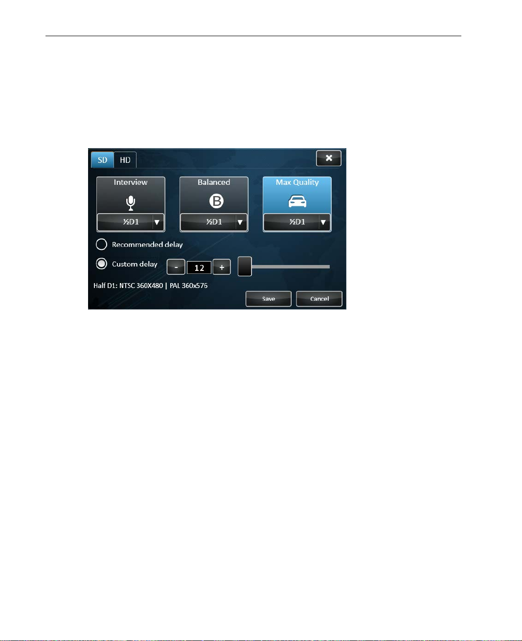
Balanced Profile
Select the Balanced Profile when the delay starts to become important, yet
an Interview delay is not mandatory. This setting provides high image quality
with medium end-to-end delay. This Profile does not have a configurable
custom delay.
Figure 33: Balanced Profile
The Balanced Profile normally uses fewer modems by eliminating those with
relatively high delay in order to reduce transmission latency. As it optimizes
the system for a relatively short delay, 5 – 12 seconds, it is subject to
interference in unstable networks (where there is an interrupted signal or
change in bandwidth). For example, when you are broadcast in g from a moving
vehicle that enters a tunnel and the signal is interrupted for a minute or two .
When using this setting there is on ly a slight room for recovery, and as a
result the broadcast may be affected.
53
Page 54
LiveU Live Video Uplink System User Guide
Max Quality Profile
This Profile is selected by default.
Select the Max Quality Profile when the quality is of prime importance and
the delay is not important.
Figure 34: Max Quality Profile
This Profile provi des th e best image quality at a potentially higher end-to-end
delay. The system is optimized for m aximum stability with more emphasis on
the integrity and quality of the transmitted video. It tells the system to use all
the available connection s in order to gain the maximum bandwidth poss ible
and configures the system to deliver the best resolution.
Max Quality Profile Delay
Max Quality profile allows for the longest delay, 12 – 60 seconds to
compensate for interferences that can occur due to various factors (for
example, broadcasting from a moving vehicle that enters a tunnel,
broadcasting from an underground basement or park ing lot or entering an
elevator while broadcastin g) . The delay is automatically set by the sy ste m
after calibration according to the selected resolution. The Recommended
delay checkbox is automatically selected to indica te that this Profile is using
the automatically delay set by the system after calibration.
54
Page 55
You can manually set the delay and overr ide the system’s automatic
Profile Button
selected resolution
recommendation by checking the Custom delay checkbox. The system then
displays the upper and lower permitted delay limits according to the
performance of the Interfaces measured in the Calibration process during the
Connect phase. You can then type in or use the slider to specify the desired
delay. Please note that reducing the delay below the system’s recommended
one may result in less video resiliency and/or image qua lity.
NOTE
Generally, as a rule of thumb, the longer the delay, the better the
system reacts to temporary air bandwidth deterioration.
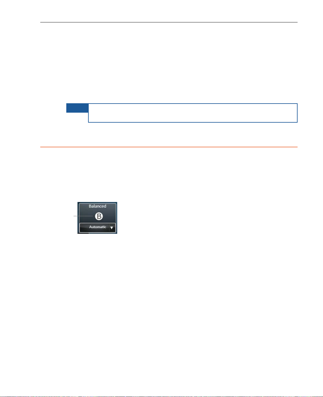
Changing a Profile’s Resolution
The video Resolution determines the horizontal and vertical size of the video
frame (picture) that is transmitte d and w he ther it is for NTSC or PAL analog
televisi on encoding systems.
The bottom area of each Profile button displays the curren tly selected
resolution.
Successful Video Transmis s ion
showing the
The same resolution optio ns are provided for all Profiles. The default option is
Automatic, whic h specif ies that the optimal resol ution for each Profile is
automatically selecte d. Typically, there is no need to change it.
An example of when you may want to change a Profile is when 3G signal
quality is fluctuating because of the en vironment or because of your lo cation.
This could happen while driving, riding the subway or while switching between
indoor, outdoor and underground locations during filming. In this case, you
may want to set the lowest resolution: CIF or ¼ HD. This resolution ensure s
proper quality under fluctuating 3G signal conditions, but does not increase
resolution when signal quality improves (as Automatic does).
55
Page 56
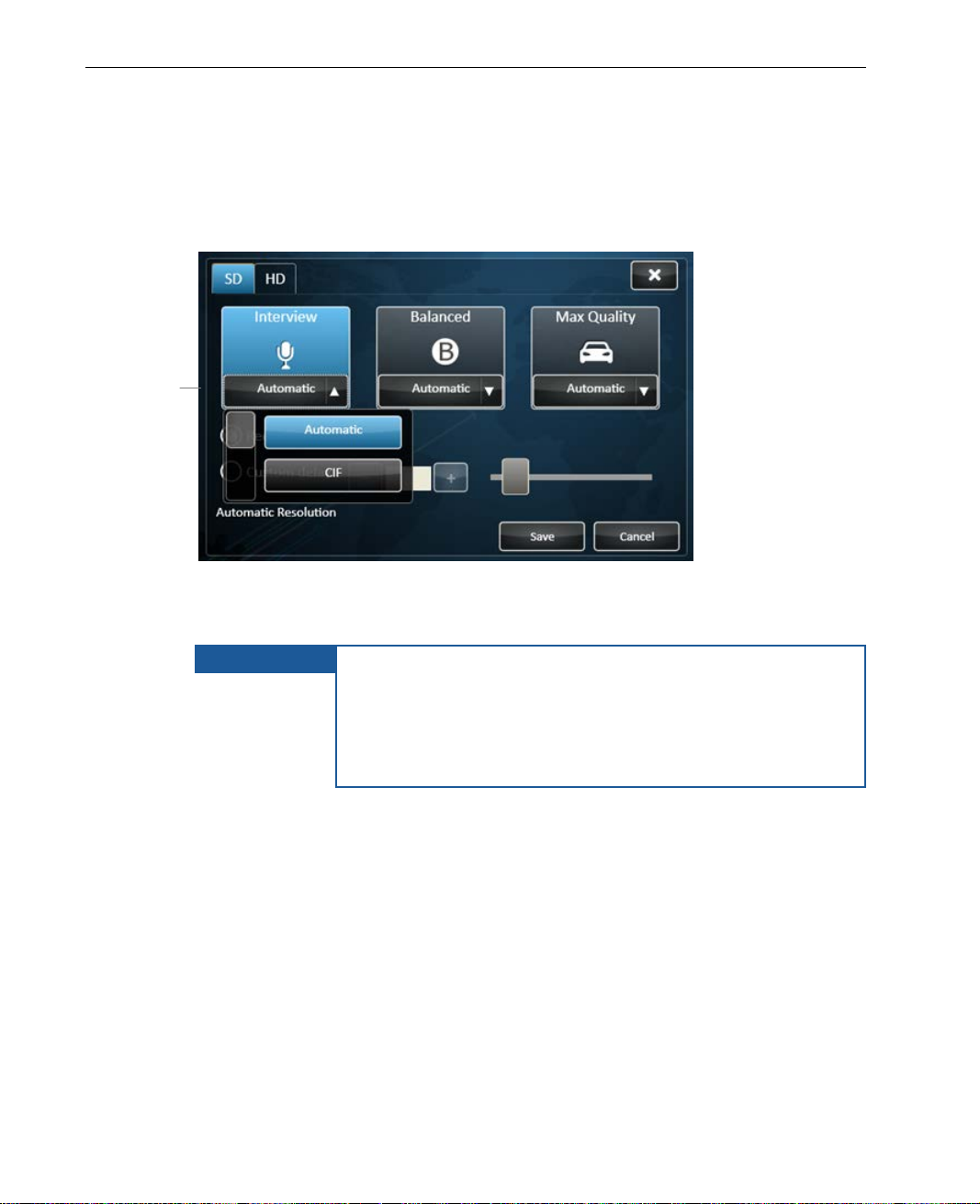
LiveU Live Video Uplink System User Guide
Tap this area of a
Profile button
and select a
resolution from
the dropdown
► To change the resolution of a Profile:
• Simply tap one of the Resolution buttons on the bottom of a Profile
button, to display a selection of resolutions suited to that profile, as shown
below:
menu
Figure 35: Changing a Profile’s Resolution
Then, tap the desired resolution in the dropdown menu.
IMPORTANT
There are limitations to when changes can be made. You
cannot select whether to enable/disable modems on the
fly. Profiles, Resolutions or Custom delay cannot be
changed during broadcast. In order to change the bitrate,
it is necessary to stop the transmission before making the
change.
Resolution Descrip tions
The same resolutions are provided for each of the three Profiles, a s follows :
LU60/LU70 devices that support HD provide either four High Definition (HD) or
four Standard Definition (SD) Resolutions for each of the three Profiles
according to the camera that is connected.
56
Page 57

Successful Video Transmis s ion
HD (High Definition)
The following resolutions are available for an HD video source on an
LU60/LU70 device.
• Web HD: 512x288: This is norma lly used for Internet output applic ations
as well as TV under certain condit ions. The optimal encoding bitrate fo r
Web HD is between 350 and 750 K bps ( or up to 1.5 Mbps total
transmission rate under harsh conditions). However, it is poss ible to start
working with Web HD fro m 250 Kbps and upwards, if necessary. This
resolution is available in either NTSC or PAL frame rates.
• ¼ HD: 640x360: This is norm a lly used for TV output applications, as well
as internet under certain conditions. The optimal encoding bitrate for ¼ HD
is between 500 and 1000 Kbps (or up to 1.8 Mbps total tr ansmission rate
under harsh conditions). However , it is possible to start working with ¼ HD
from 400 Kbps and upwards, if necessary. This res olution is available in
either NTSC or PAL frame rates.
• ½ HD 960x540: This is normally used for TV output applications as well
as advanced internet under certain conditions. The optimal encod ing
bitrate for 1/2 HD is between 800 and 1500 Kbps (or up to 2. 5 Mbps total
transmission rate under harsh conditions). However, it is poss ible to start
working with1/2 HD from 700 Kbps upwards, if necessary. This resolution
is available in either NTSC or PAL frame rates.
• HD: 1920x1080 | 1280x720: This is normally used for TV output
applications. The opt imal encoding bitrate for HD is between 1000 and
2500 Kbps (or up to 3.5 Mbps total transmission r ate un de r harsh
conditions). However, it is possible to start working with HD fro m 800 Kbps
upwards, if necessary. This resolution is available in either NTSC or PAL
frame rates.
57
Page 58

LiveU Live Video Uplink System User Guide
SD (Standard Definition)
The following resolutions are available for an SD video source on LU60/LU70
devices.
• CIF: NTSC 360x240 | PAL 360x288: This is normally used for Internet
output applications, as well as TV under certain conditions. The op timal
encoding bitrate for CI F is between 350 and 750 Kbps (or up to 1.5 Mbps
total transmission rate under harsh conditions). However , it is possible to
start working with CIF from 250 Kbps and upwards , if necessary. This
resolution is available in either NTSC or PAL.
• ½ D1: NTSC 720x240 | PAL 720x288: This provides clos e to Full-D1
quality. Use this resolution when high quality is needed and the uplink
bitrate is limited. The lowest bi trate that should be considered in this case
is approximately 512 Kbps. The optimal bitra te for Half-D1 is between
750 Kbps and 1.5 Mbps.
• VGA: NTSC Only | PAL 640x480: This provides ne a r Full-D1 qu al ity ,
which is used by some websites. Use th is resolution when a higher quality
is needed and enough bitrate is ava ilable. The lowest bitrate that sho u ld be
considered in this case is about 7 50 Kbps. The optimal bitrate for VGA is
between 1 Mbps and 2 Mbps.
• D1: NTSC 720x480 | PAL 720x576: This is the highest SD resolution
currently supported by the LU live video uplink, and is normally used for
SD live TV broadcasts when the highest q uality picture is required. Only
consider transmitting Full-D1 when the overal l available bitrate is over
1 Mbps. The optimal video bitrate for Full-D1 transmission is between 1.5
and 2 Mbps.
Saving the Profil e
To apply the Profile definitions that you have selected, tap the Save button.
To close this window and retur n to the m ain window, tap the
58
button.
Page 59

5
File Transfer
This chapter describes how to use the LU to transfer files from the field directly
to the LU-1000 server.
Transferring Files
The LU Live Video Uplink System enables you to transfer prerecorded files to
the LU-1000 server so that they may be saved f o r future use. This feature can
also be used to transfer any other type of file, such as text files, documents
and so on. Files can even be transferred while the unit is broadcasting
(playing).
Files can be transferred from the LU unit itself or f r o m a USB device, such as a
camera with USB interface attached, which can be attached to the LU unit.
One or more files can be selected to be tr ansf erred.
The files are stored on the LU-1000 server in the directory designated for this
purpose.
► To transfer files from the LU to the LU-100 0 server:
1 If the LU is not already connected to the LU-1000 server (as indi cated by
the Connect button displaying the word Reconnect), then establish a
connection by turning on the LU unit and tapping the Reconnect button
on the touch screen.
2 If the file to be transferred is on a USB Disk on Key, then insert it into the
LU unit.
59
Page 60
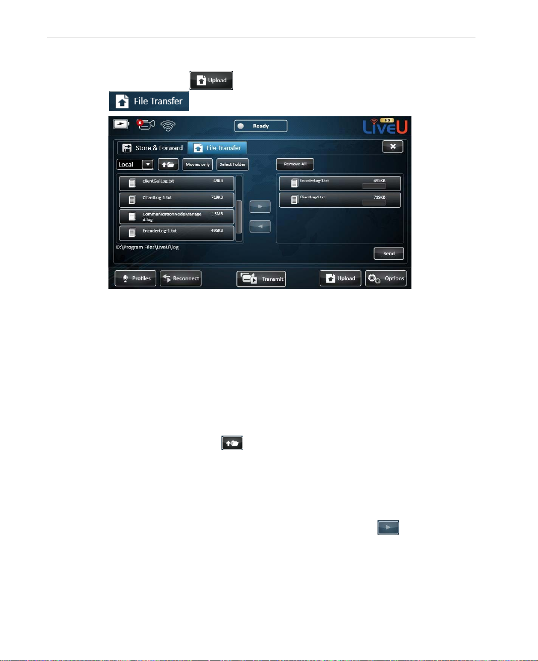
LiveU Live Video Uplink System User Guide
3 Tap the Upload button and then tap the File Transfer
tab to dis play the following window:
Figure 36: LU File Transfer
The Status icon changes to transferring in order to indicate that the
system is in File Transfer mode.
The left side of this window displ ays the f iles that can be selected to be
transferred. These files are located on the LU or on the disk on key
inserted into the LU.
The right side of the window displays the list of files that have been
selected to be transferred.
4 Use the browse button
to go up one directory to locate the files to be
sent to the LU-1000 server, for example, to brows e f iles on the disk on
key.
5 You can tap the Movies only button to filter the display of files so that
only movie files are shown.
6 Select one or more files and tap the right arr o w button
to move the
file(s) to the list on the right. These are the files that can be tran sf e r red to
the LU-1000 server.
60
Page 61
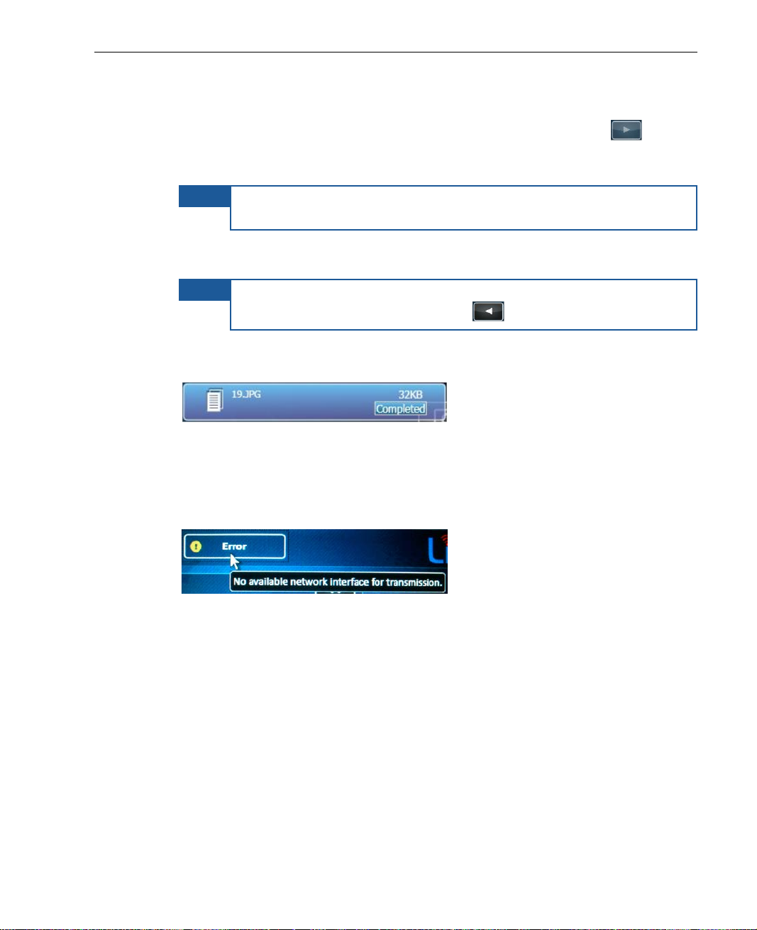
File Transfer
7 You can tap the Select Folder button to display a list of folders. Yo u can
then select one or more folders and tap the right arrow button
to
move the folder(s) to the list on the right. These are the folders that can
be transferred to the LU-1000 serv e r.
NOTE
You can tap the Remove All button to clear the l ist of files and
folders (on the right) to be sent to the LU-1000 server.
8 Tap the Send butto n to start transferring the files in the list on the right to
the LU-1000 server.
NOTE
To remove a selected file fro m the list on the r ight, simply select it
and then tap the left arrow button
.
After the transmission has been successfully completed, the fol lowing
message is displayed.
Figure 37: Completed File Transmission
If an error occurs during File Transfer mo de, the transmission stops, and
an Error status is displayed. Yo u can see the r eason for the error by
tapping the status icon, as shown below:
Figure 38: Camera Disconnected or Off
The session will automatically continue transmission as soon as the
connection is reestablished.
61
Page 62

LiveU Live Video Uplink System User Guide
Blank page for double-sided printing
62
Page 63

6
Store & Forward
This chapter describes how to use the LU Store & Forward feature to record
video sessions, forward them to the LU-1000 server, or simultaneously record
and forward files from the field directly to the LU-1000 server.
Storing and Forwarding Files
The LU Live Video Uplink System enables you to store recorded files, transfer
prerecorded files or simultaneously store and forward the recorded file to the
LU-1000 server.
The Store & Forward feature enables you to transfer files under the optimal
conditions, in terms of quality of broadcasting, and regardless of broadcasting
conditions that exist during recording.
Files can be forwarded from the LU unit itself or from a USB device, such as a
camera with USB interface attached, which can be attached to the LU unit.
The files are stored on the LU-1000 server in the directory designated for this
purpose.
63
Page 64
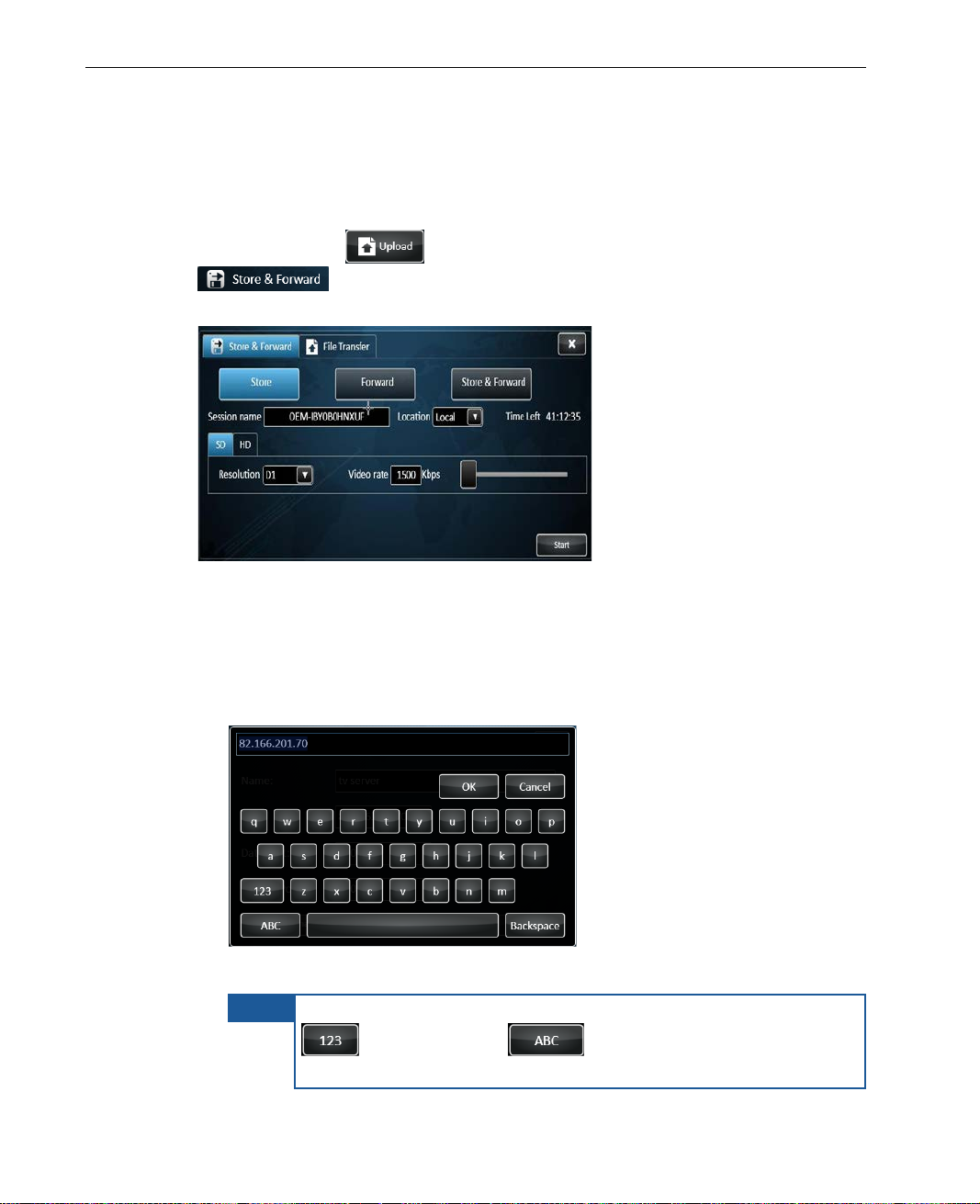
LiveU Live Video Uplink System User Guide
NOTE
To switch the keyboard to enable the e n tr y of numbers, tap the
► To store recorded files:
1 If the file to be stored is on a USB Disk on Key, the n inser t it into the LU
unit.
2 Tap the Upload
button and then tap the Store & Forward
tab to display the follow ing window, and tap the Store
button to display Store related fields.
Figure 39: Store Session Configuration
3 Fill in the fields as follows:
Session Name: The name assigned to the recording file. Tap the field
to display a keyboard, as shown below:
Figure 40: Virtual Keyboard
button. Tap the button to enable the entry of
characters.
64
Page 65
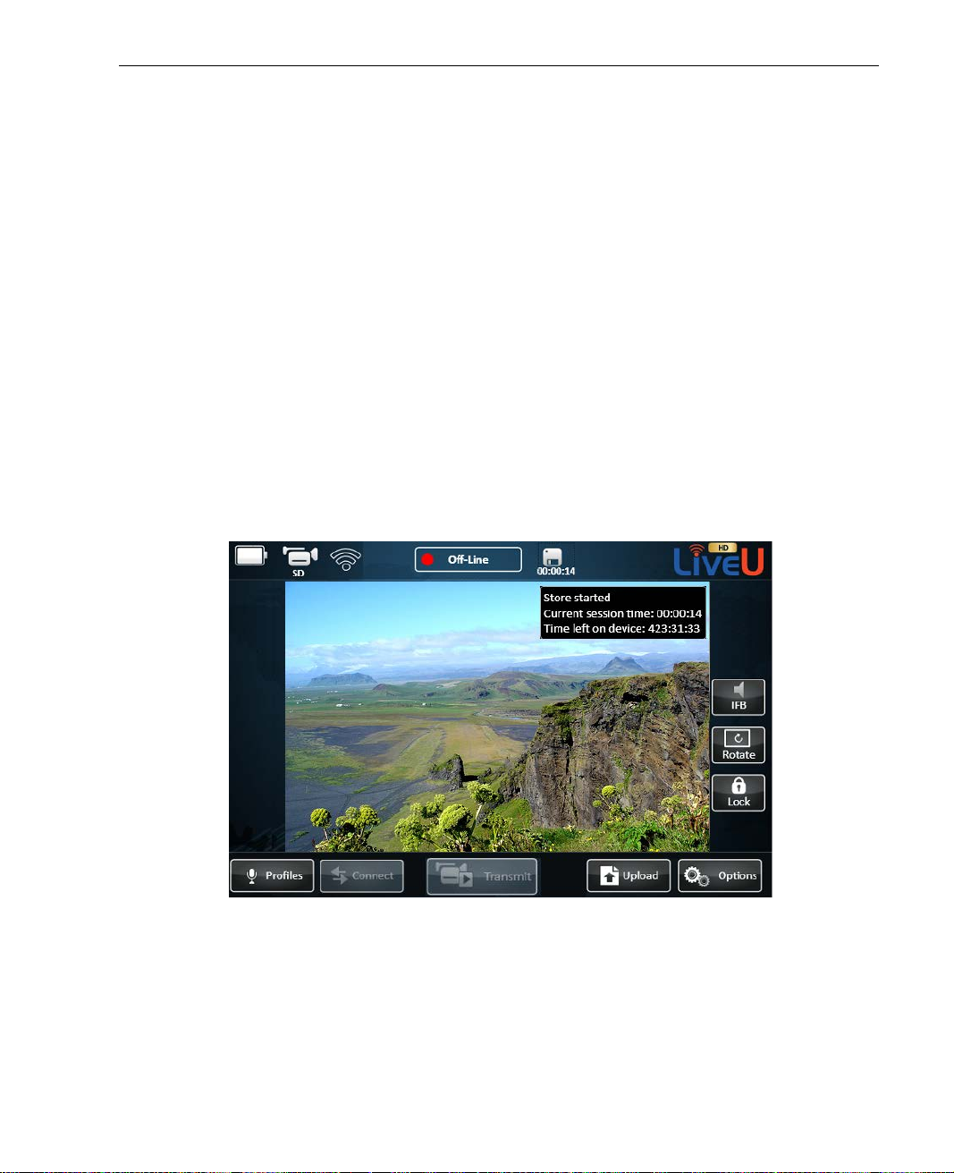
Store & Forward
Location: Indicates where the file will be saved. You can save the file
locally on the device, or on a USB Disk -on-Key.
Time Left: The memory space left for the r ecording is calculated
according to the set resolution and video rate. The set time left refers
to a maximal quality record ing. This field is no n-editable.
Resolution: Sets the resolution options according to the connected
camera (Standard or HD). The set reso lution determines the video
rate. To set the resolution tap the arr o w and select from the drop-down
list.
Video Rate: Calculated according to set Resolution. This field is
non-editable.
4 After setting the fields, tap Start. When the recording starts, an icon
appears next to the Status Indicator, dis playing time elapsed since the
recording started. Tapp ing the icon displays more inform ation about the
recording.
Figure 41: Store Session in Progress
65
Page 66
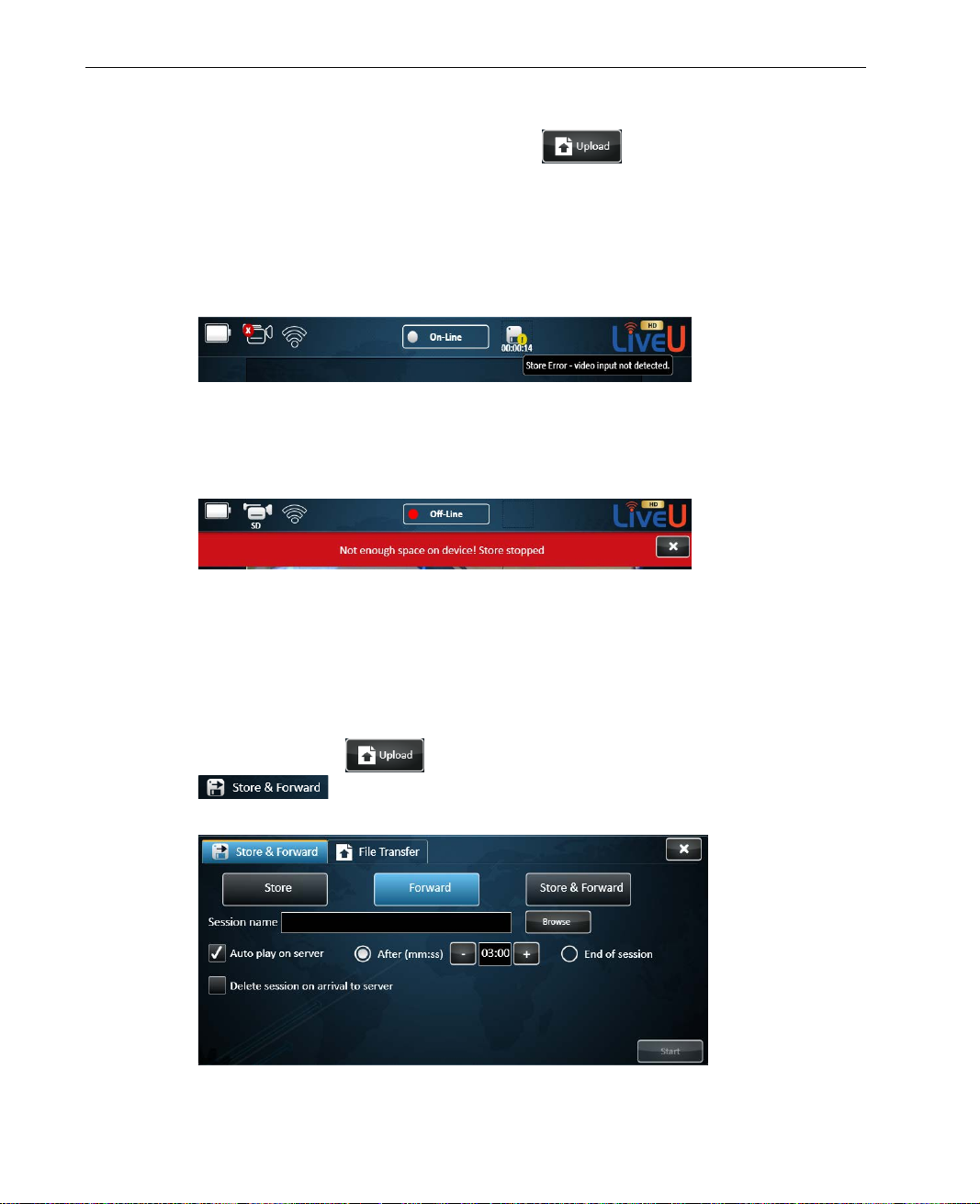
LiveU Live Video Uplink System User Guide
5 To stop the recording, tap the Upload button and then tap Stop.
If the camera is disconnected during transmission, an error status is
displayed on the Store icon and the c amera icon indicates that is it
disconnected. Tapping the Store icon displays a text message. T h e sto re
session is not stopped followin g camera disconnection and after
reconnecting the camera, recording is automatically resumed.
Figure 42: Store Error – No Video Input
If the LU is about to run out of memory space, a warning appears in red
and the store process is stopped until the user frees more memory space.
Figure 43: Warning Message – Not Enough Space
► To forward recorded files:
1 If the file to be forwarded is on a USB Disk on Ke y , then insert it into the
LU unit.
2 Tap the Upload
button and then tap the Store & Forward
tab to display the follow ing window, and tap the Forward
button to display Forward related fields.
Figure 44: Forward Session Configuration
66
Page 67
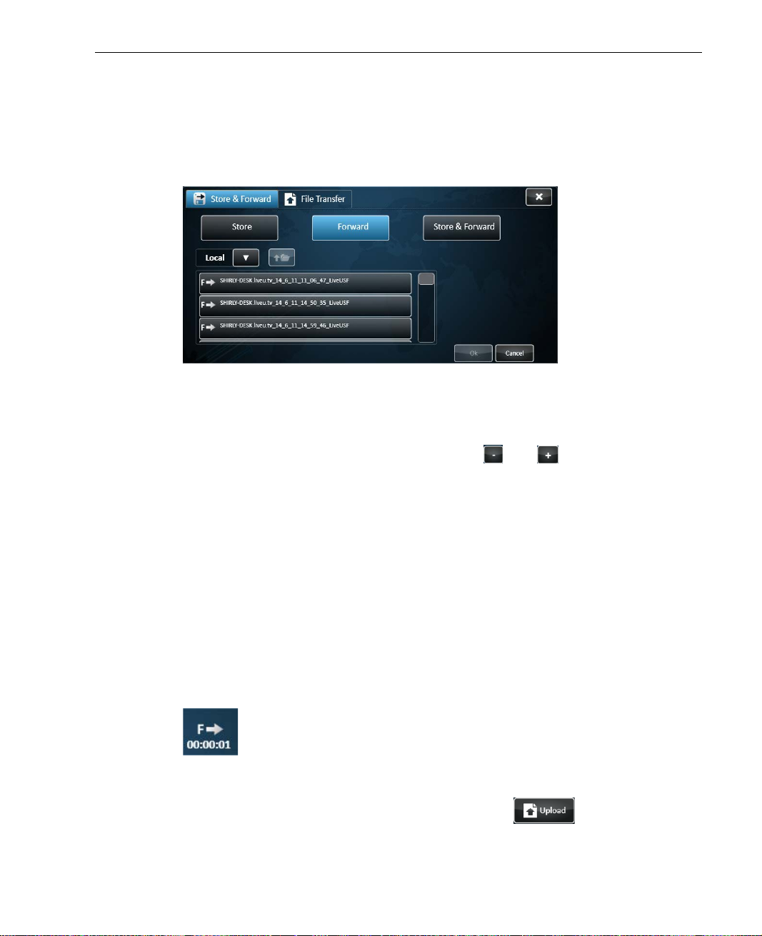
Store & Forward
3 Set the Session Name field by tapping Browse and select ing the relevant
session from the session list. If th e r e levant session is stored on a USB
Disk-on-Key, use the bro wser to open the file list on the Disk-on-Key and
select the session. To close the brow ser, tap OK.
Figure 45: Forward Browse
4 If you want the forwarded file to be automatically played on the server,
check the Auto play on server option and select whe n th e auto play will
start – either after a preset period (use the
and buttons to set the
time period), or following the end of the forwarding session.
5 If the fo rwarded fil e is loca ted on the device, it is automatically deleted
when forwarding is completed. Therefore, when forwarding a session
locally, the Delete session on arrival to server option is checked
automatically and cannot be unchecked. When forwarding a session from a
USB Disk-on-Key, you can decide whether to delete or keep the forwarded
session.
6 After setting the fields, tap Start. If the LU is not connected, the modems
are dialed automatically. When the LU con n ects the status indicator
changes to On-Line followed by Forwarding as t h e session starts. A
forwarding icon ap pears, i ndicating the tra nsmission rate.
Figure 46: Forward Icon
To stop the forwarding session, tap the Upload button and then
tap Stop.
67
Page 68
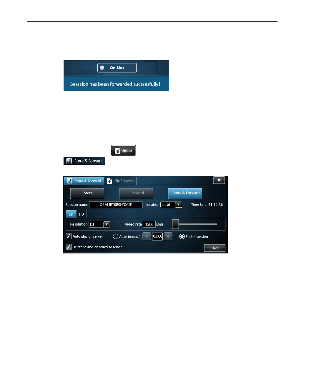
LiveU Live Video Uplink System User Guide
When forwarding is completed a message is displayed, indic a ting the
session is forwarded successfully.
Figure 47: Forward completed message
► To store and forward recorded files:
1 If the file to be stored and forwarded is on a USB Disk on Key, then insert
it into the LU unit.
2 Tap the Upload
button and then tap the Store & Forward
tab, and tap the Store & Forward button to display Store
& Forward related fields.
Figure 48: Store & Forward Session Configuration
68
Page 69
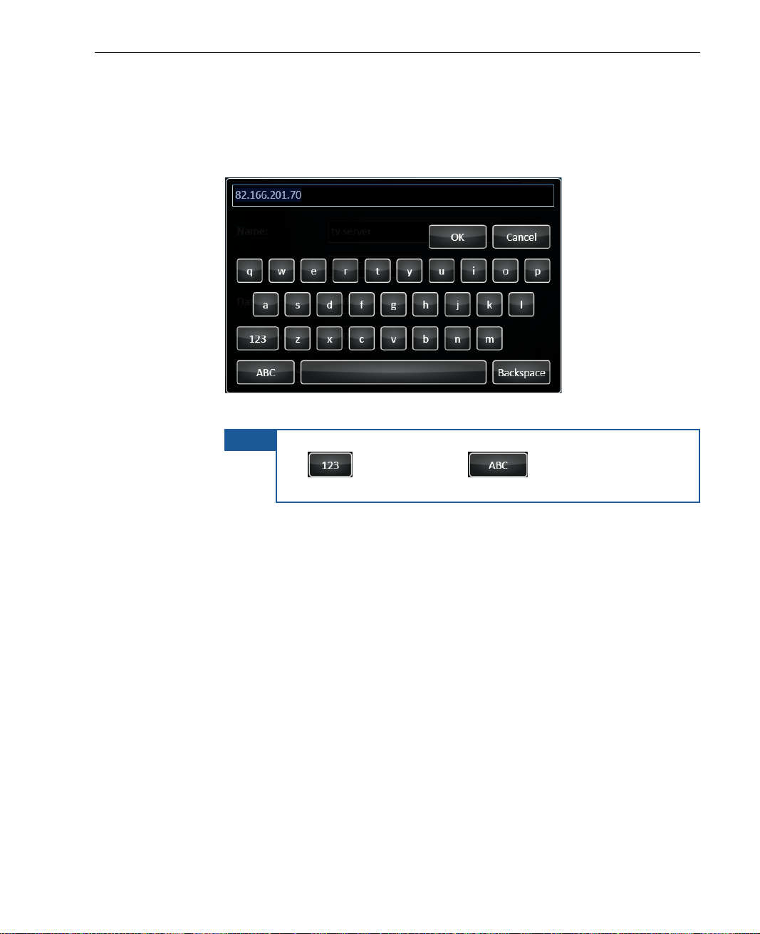
3 Fill in the fields as follows:
Session Name: The name assigned to the recording file. Tap the
field to display a keyboard, as shown below:
Figure 49: Virtual Keyboard
Store & Forward
NOTE
To switch the keyboard to enable the e n tr y of numbers, tap
the
button. Tap the button to enable the
entry of characters.
Location: Indicates where the file will be saved. You can save the
file locally on the device, or on a USB D i sk-on-Key. Tap the arrow to
select the relevant option fr om the drop-down list.
Time Left: The memory spac e left f o r th e r e co r ding is calculated
according to the set resolution and video rate, and is set
automatically. The set time left refers to a maximal quality
recording. This field is non-editable.
Resolution: Sets the resolution options according to the connected
camera (Standard or HD). Tap the arrow to select the relevant
option from the drop-down list. The set resolution determ ines the
video rate.
Video Rate: Calculated according to set R esolution and is set
automatically. This field is non-editable.
69
Page 70
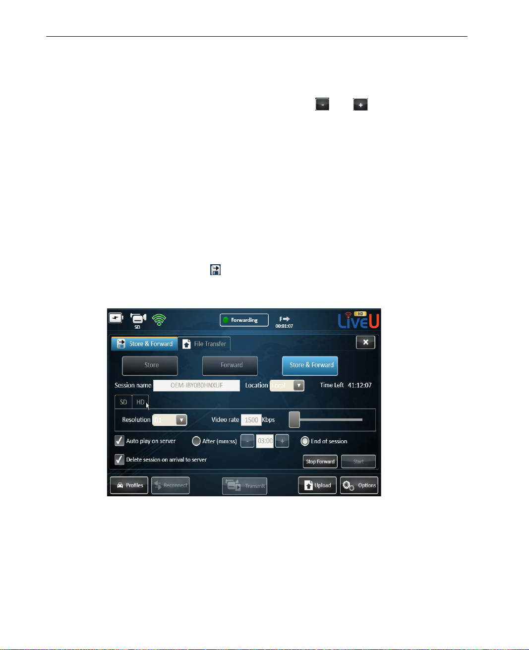
LiveU Live Video Uplink System User Guide
4 If you want the forwarded file to be automatically played on the server,
check the Auto play on server option and select whe n th e auto play will
start – either after a preset period (use the
time period), or following the end of the forwarding session.
5 If the fo rwarded fil e is stored on the de vice, it is autom a tically d eleted
when forwarding is completed. Therefore, when forwarding a session
locally, the Delete session on arrival to server option is checked
automatically and cannot be unchecked. When forwarding a session from a
USB Disk-on-Key, you can decide whether to delet e or keep the forwarded
session.
6 After setting the fields, tap Start. If the LU is not connected, the modems
are dialed automatically. When the LU connects the status indicator
changes to On-Line followed by Forwarding as the session starts. A
Store & Forward icon
recording started. Tapping the icon di splays more information about the
ongoing session.
and buttons to set the
appears, displaying time elapse d si n ce th e
Figure 50: Store & Forward Session in P rogress
70
Page 71
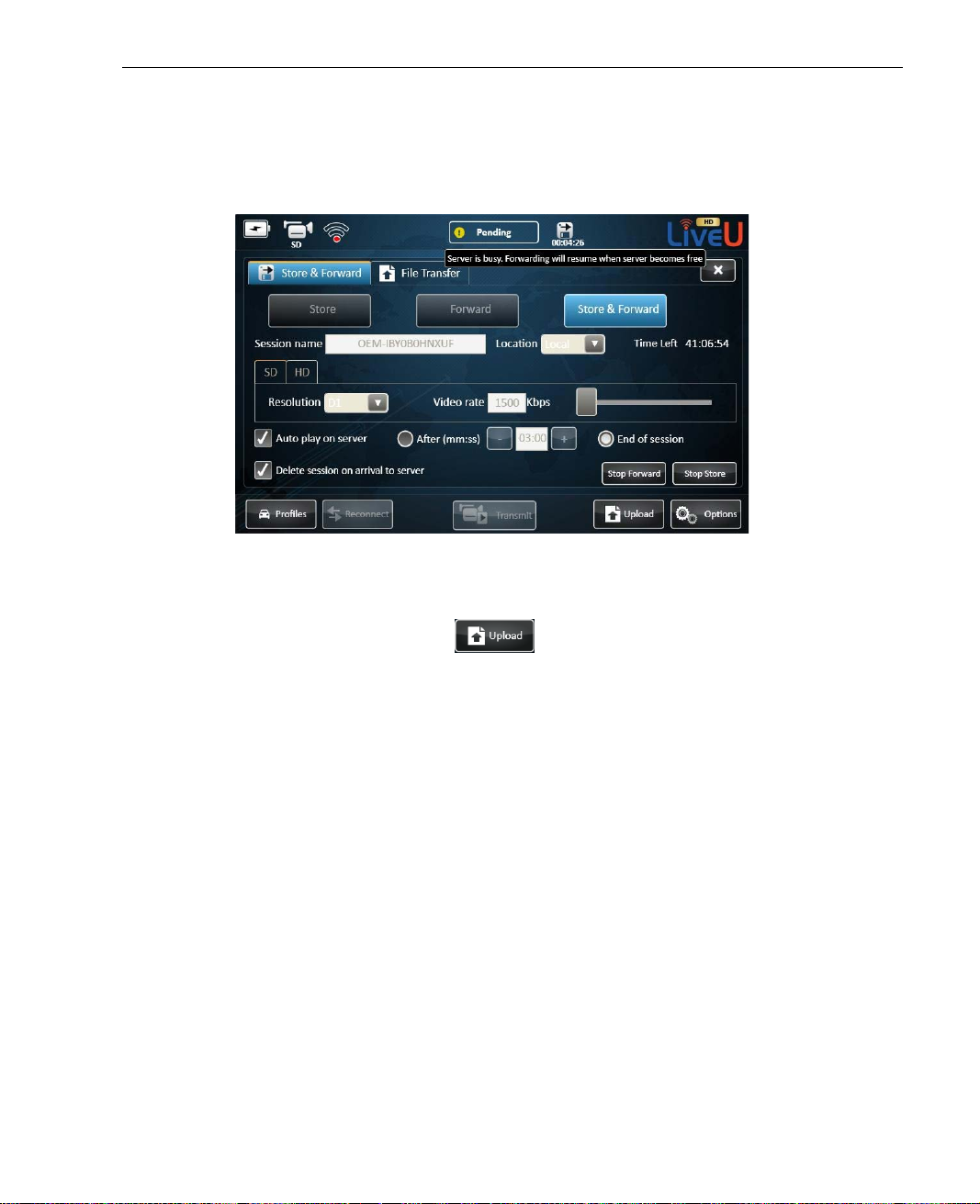
Store & Forward
7 If the server is busy, the session is stopped. The status indicator changes
to Busy and a message appears. The session is resumed when the
connection to the server is restor ed.
Figure 51: Store & Forward Session – server is busy
8 To stop the Store part of the session, tap Stop Store. To stop the Forward
part of the session, tap Stop Forward. To stop the Sto re & Forward
session, tap the Upload
button and then tap Stop.
71
Page 72

LiveU Live Video Uplink System User Guide
Blank page for double-sided printing
72
Page 73

7
Configuration and
Settings
This chapter describes how to adjust t h e automatic setup of the LU, if
required, and how to define it as an Acce ss Point.
This chapter contains the following sections:
• Purpose and Scope, page 73
• Options Button, page 74
• Interfaces, page 75
Purpose and Scope
• Servers, page 90
• Settings, page 92
• Support, page 103
• Power, page 104
The LU enables you to monitor the configuration and performance of the
Interfaces, as well as adjust the setup of the device as needed. It also en ables
you to display the number for getting support, reset the system, to select from
a predefined set of soft keys and more.
The initial connection process take s place when the Connect button is tapped.
During this process, the system automatically calibrates the interfaces that are
available and connected and determ ines the best parameters for maximum
broadcast efficiency.
Neither audio nor video bit rates can be changed dur ing broadcast.
73
Page 74
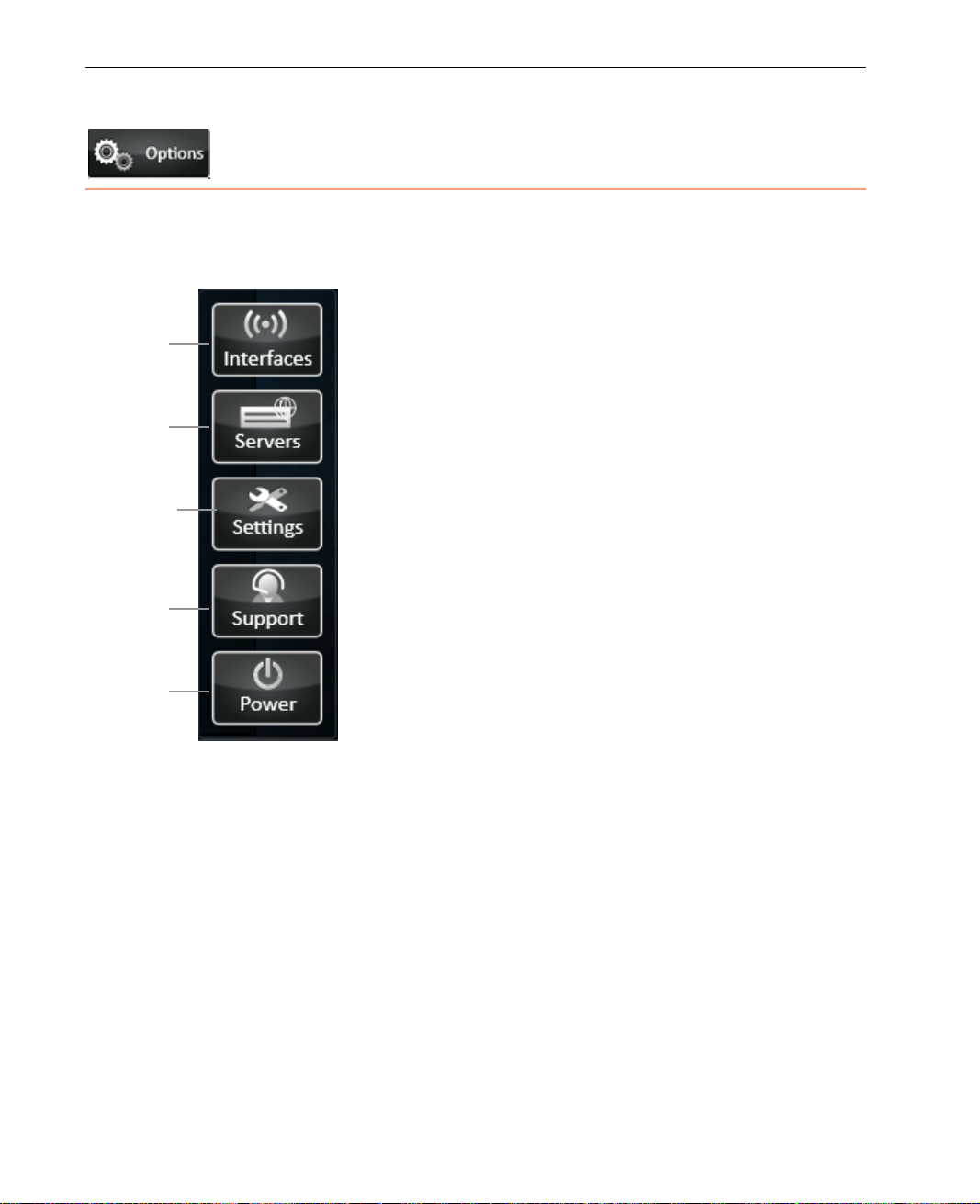
LiveU Live Video Uplink System User Guide
Interfaces
Settings
Servers
Support
Power
Options Button
The Options button displays information about the broadcasting interfaces,
configuration settings and servers. It also enables you to access remo te
support and to restart or power down the u nit.
Figure 52: Setup Options
The Options button provides the following configuration o ptions:
• Interfaces, page 75
• Servers, page 90
• Settings, page 92
• Support, page 103
• Power, page 104
74
Page 75
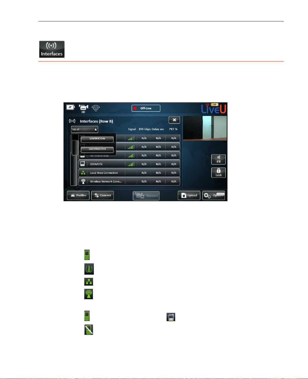
Configuration and Settings
Interfaces
The Interfaces button enables you to view and configure the interfaces
(modem connections) of the LU. It displays the Interface Table, wh ich shows a
list of all of the interfaces to which the LU unit is able to connect, as shown
below:
Figure 53: Configuration – Interface Table
The following information is displayed for each interface. A more detailed
description is provided for some of these fields on page 78.
• Interface Status Icon:
Represents a cellular network.
Represents cellular interfaces of the Xtender.
Represents a Local Area Network (LAN).
Represents Wi-Fi networks and external modems, as described in
the Defining a Wi-Fi Interface section on pag e 79.
Green means Connected. White means Not Connected.
Strike-through means Manually Disabled by the user.
Instructions for manually disabli ng an inter face are provide d below.
75
Page 76
LiveU Live Video Uplink System User Guide
• Interface Name: Detected network’s name.
• Signal Strength: Signal strength (RSSI level).
• BW kbps.
• Delay in seconds.
• PKT%: Efficiency. This specifies the per centage of quality throughput. The
higher this value, the better.
• Interface (A) or (B): The LU60/LU70 products that support dual SIM are
provided with mod ules. A module has two rows of SIM cards: A and B. Two
SIM cards of each type are provided in these types of devices, one on each
row. Only one row of SIM cards is used at a t ime. This window indicates
the letter of the row (A or B) that is used, as f o llows:
Figure 54: Interface (A) or (B)
You may refer to Utilities section on page 98 for a description of how to
select which row of SIM cards is used.
Devices that only have a single row o f SIM cards do not display a letter (A
or B) in this window.
• Interfaces dropdown list: This dropdown list enables you to specify the
interfaces to be used for transmission. The following options are available:
Use All: Indicates that all interfaces are use d f o r transmission.
LAN/WiFi Only: Specifies that only LAN and Wi-Fi interfaces are used.
This option disables all modems. When this option is selected, all the
Interface Status icons in the Interfaces window appear disabled.
Guaranteed Only: Indicates that only interfaces specified to use a
guaranteed bandwidth rate are used for transmission. This option only
applies to LAN interfaces, and not to cellular or Wi-Fi interfaces. For an
interface to be identified as a guaranteed-only one, its Guaranteed
rate checkbox must be checked, as described on page 78.
NOTE
In Use All mode, the minimum Custom Delay is 1.6 seconds. In
Guaranteed Only mode, the minimum Custom Dela y is 1.4
seconds. For more details about se tting the Custom Delay, see
page 52.
76
Page 77
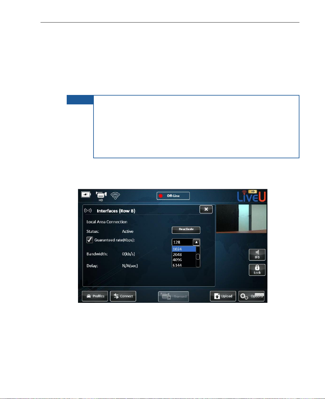
Configuration and Settings
Defining an Interface
Cellular and Local Area Network (LAN) interfaces ar e automatically detected by
the LU and displayed in the Interfaces page described above. T h e fo llowing
describes how to display more information about an interface and to ma nually
disable/e n able it.
NOTES
► To define a guaranteed LAN interface:
1 Tap an interface row to display the following window:
You may refer to the Defini ng a Wi-Fi Interface section on page 79
for a description of how to define a Wi-Fi interface.
You may refer to the Xtender Wi-Fi Link sec tion on page 86 for a
description about how to view Wi-Fi link statis tics.
You may refer to the Manual R oaming section on page 86 for a
description of how to select a networ k other than the one to which
the modem is registered.
Figure 55: Interfaces
77
Page 78
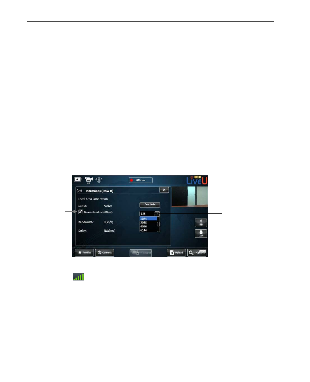
LiveU Live Video Uplink System User Guide
Specify the maximum
The following information is displayed for each interface:
Name of the detected network.
Status: Status of the connection of this interface. It can be Active or
Deactivated. Tap the Deactivate button to deactivate the connection.
You can change it back by tapping the y e s. The system will
automatically attempt to connect to this interface when it is rebooted.
When an interface is deactivated, the sy ste m no longer attempts to use
this modem when connecting.
Guaranteed rate: A checkbox indicating whether an interface should
use a guaranteed bandwidth rate for transmission, in order to ensure
reliable t ransmis sion.
When selecting this checkbox, you should specify the maximum uplink
bandwidth to be used in t h e adjacent dropdown list. This value is used
for satellites (for example, BGAN, Ka-Sat), so select the bandwidth
according to the committed uplink ra te of the satellite.
uplink bandwidth for
transmission here.
Figure 56: Guaranteed-rate Interface Option
Signal level: Signal strength (RSSI level). Thi s field only appears
for modems.
Bandwidth: Bandwidth of the interface, in kbps, as seen during the
calibration ph ase
Delay: Delay of the connection as detected during the calibration
phase.
78
Page 79
Configuration and Settings
Defining a Wi-Fi Interface
The LU automatically detects an d attempts to connect to the Wi-F i int er f a c e s
in its vicinity. The LU connects on ly to on e Wi-Fi network and will attempt to
do so according to the order that you define, as described below. The LU
automatically stores and reu ses the latest passwords that you enter e d fo r each
Wi-Fi network.
A single bar appears in the Interfaces pa ge ( as described in the Interfaces
section on page 75) to represent all currently and previously detected Wi-Fi
networks.
Figure 57: Wireless Network Connection
The icon appears green if any Wi-Fi network is connected and white
otherwise.
NOTE
You may refer to the Defining an Interface section on page 77 for a
description of how to define a cellular interface.
79
Page 80
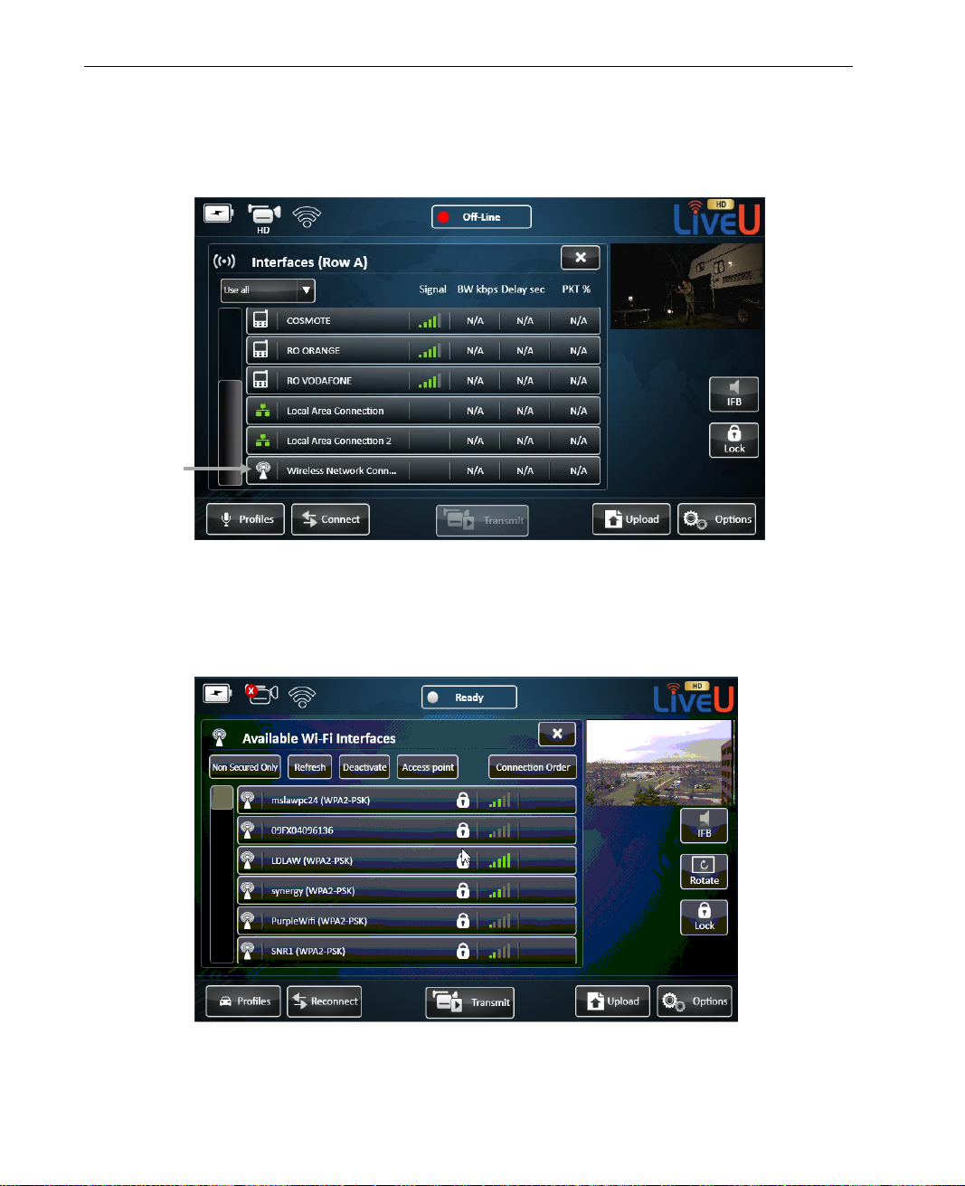
LiveU Live Video Uplink System User Guide
► To define a Wi-Fi interface:
• Tap the Wireless Network Connection row, as shown below:
Figure 58: Wi-Fi Interfaces
The following window is dis played l isting the currently available Wi-Fi
networks near the LU and all the Wi-Fi profiles that wer e save d previously
on this LU (as described o n page 81).
Figure 59: Available Wi-Fi Interfaces
80
Page 81
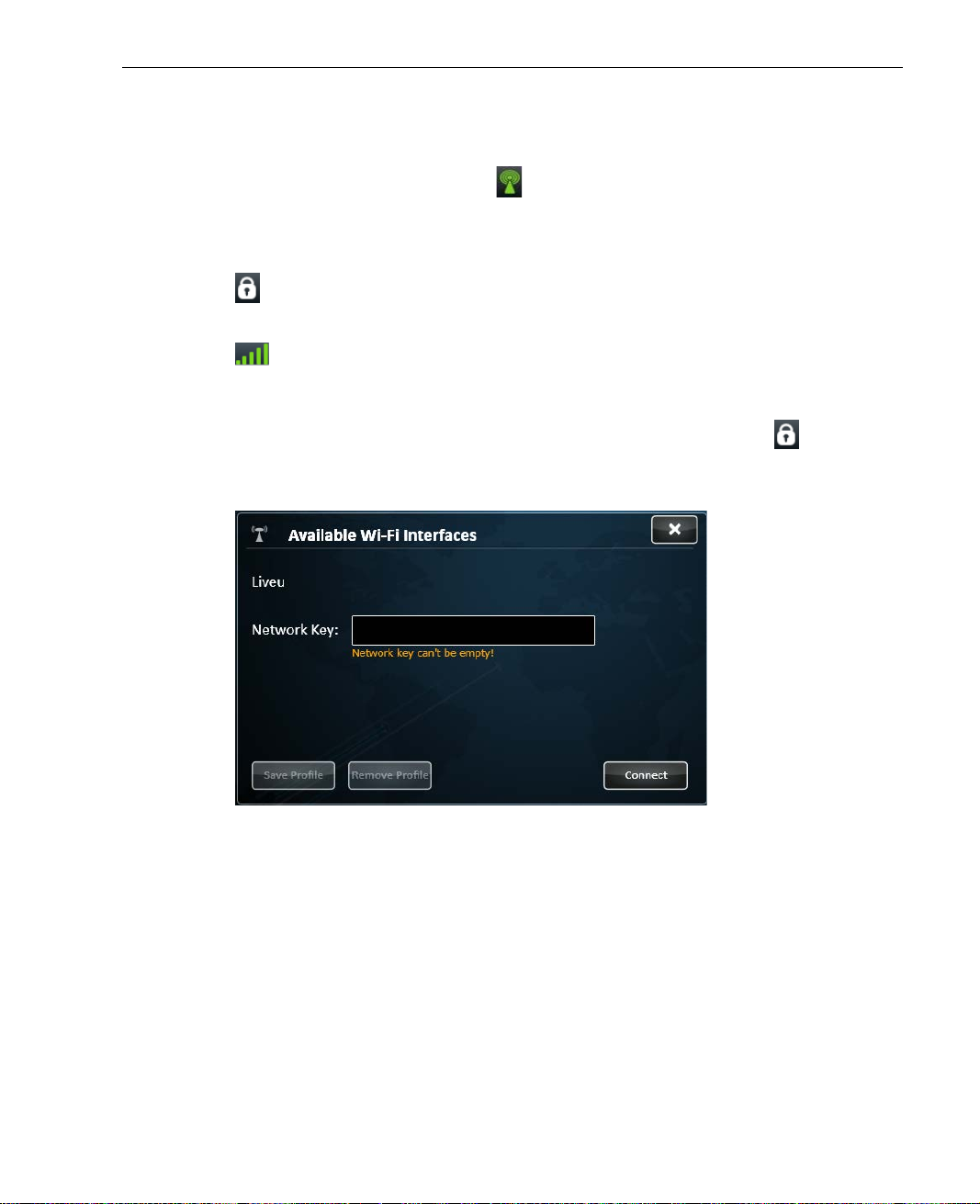
Configuration and Settings
The following information is displayed for each interface.
• Interface Status Icon: The icon appears green for each Wi-Fi
network that is connected and white otherwise.
• Name of the detected network.
• : This icon appears for secured Wi-Fi netw o rks, meaning that a Network
Key (password) is requ ire d.
• Signal Strength: Wi-Fi signal strength.
The following options are a vailable in this wi ndow:
• Profile Window: Tap o n any Wi-Fi network row that has an icon to
display the following window in which you can enter the Network Key
(password) that enables access to this Wi-Fi network.
Figure 60: Wireless Network Key
Once you click the Save Profile button, this Wi-Fi network is saved along
with its profile, meaning its Network K e y . You can tap the Connect button
after you enter the Network Key to attempt to connect to that Wi-Fi
network immediat ely.
Tapping the Remove button, removes the Network Key that you define d
here and the definition of this Wi-Fi network. This means that you will have
to reenter the network’s password to connect to it.
81
Page 82
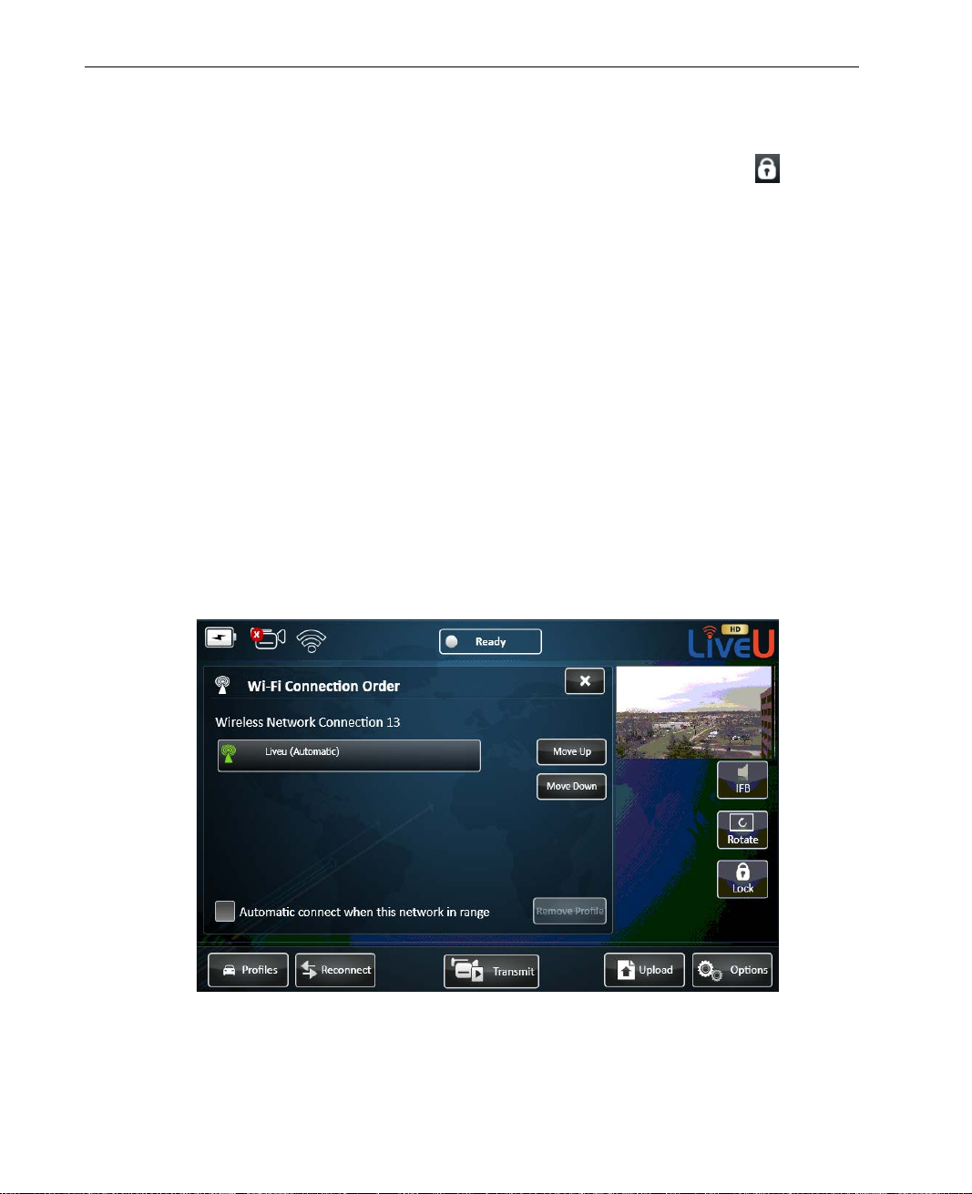
LiveU Live Video Uplink System User Guide
• Non Secured Only Button: Secured Wi-Fi networks require that you
enter a Network Key. These networks appear in the list with an
icon.
Tap Non Secured Only button to display only non-secured Wi-Fi
networks, meaning network s that do no t r equire a Network Key.
• Refresh Button: The LU autom atically refreshes the list of detected Wi-Fi
networks periodically. Tap this bu tto n to r e f resh this list immediately.
• Deactivate Button: Tap this button to deactivate this Wi-Fi network so
that it is not used during transm ission.
• Access Point Button: Tap this button to define the LU as an Access Point.
This LU can then provide an Internet connection to wireless devices, such
as a laptop. You may refer to the Access Po int section on page 83 for a
description of how to configure the cellular modem through which the LU
connects to the Internet.
• Connection Order Button: Tap this button to define the order in which
the LU attempts to connect to Wi-Fi networks. The LU only connects to first
Wi-Fi network to which it succeed s to co nn ect. The following window is
displayed:
Figure 61: Wi-Fi Connection Order
82
Page 83
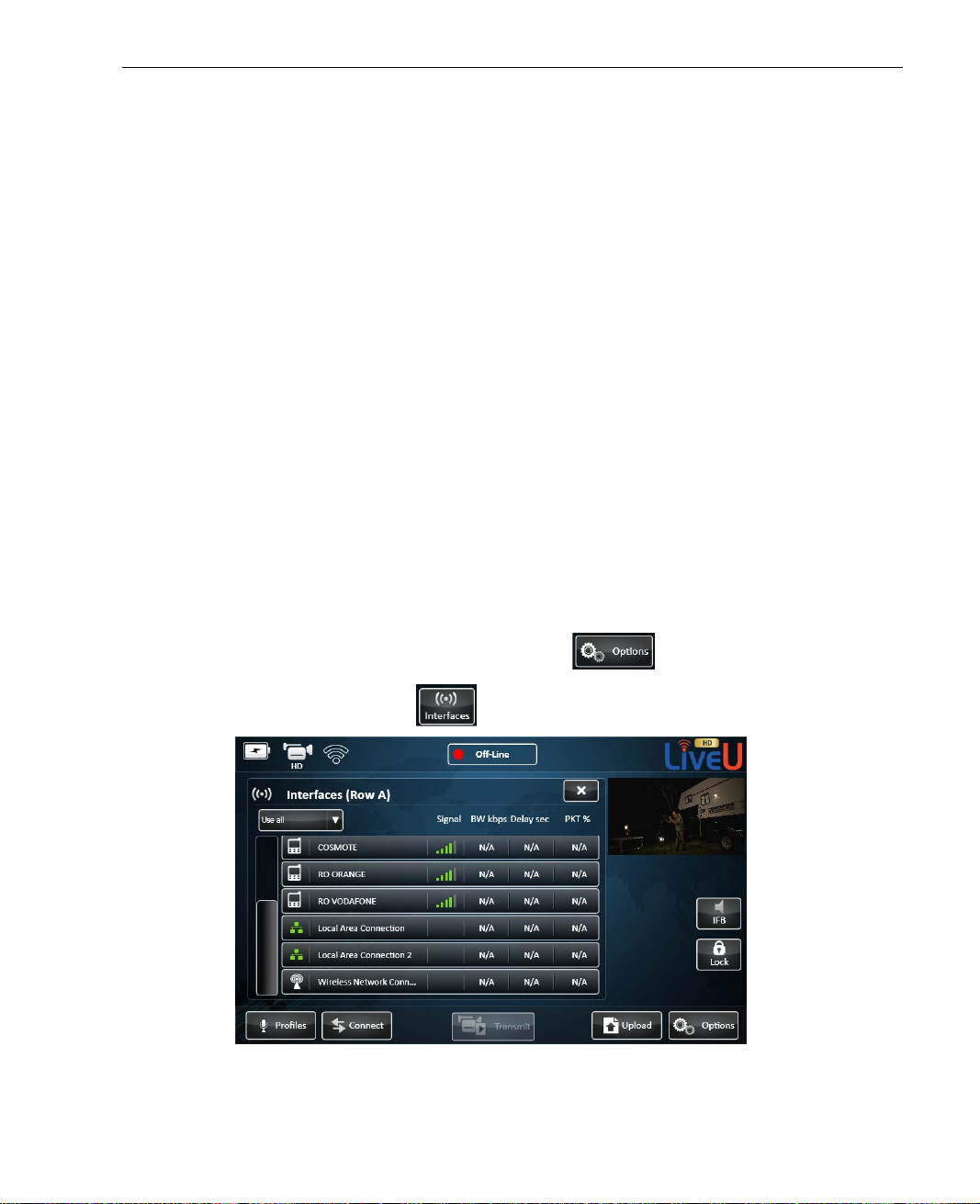
Configuration and Settings
Select a Wi-Fi network and tap the Move Up button or the Move Down
button to arrange their order. T h e LU attempts to connect in order from
top to bottom. Once it succeeds to conn ect to one network, it stops trying.
You can give one of the networks priority whenever it is in the vicinity, by
tapping it and then checking the Automatic connect when this network
in range checkbox. This means th at the LU co n nects to this network when
it is detected even if it is not higher in the list than other detected
networks.
Access Point
The LU can serve as an access point. This means that it can enable a wirele ss
device(s), such as a laptop, to con ne ct wirelessly to the Internet throu gh its
cellular modems. The wireles s device connects to the LU via Wi-Fi and the LU
provides Internet access usin g its cellular connection.
This functionality is only availabl e while the LU is no t transmit ting video.
► To define the LU as an Access Point:
1 In the main window, tap the Options button.
2 Tap the Interfaces
Figure 62: Defining an Access Point – 1
button. The followin g window is displayed:
83
Page 84
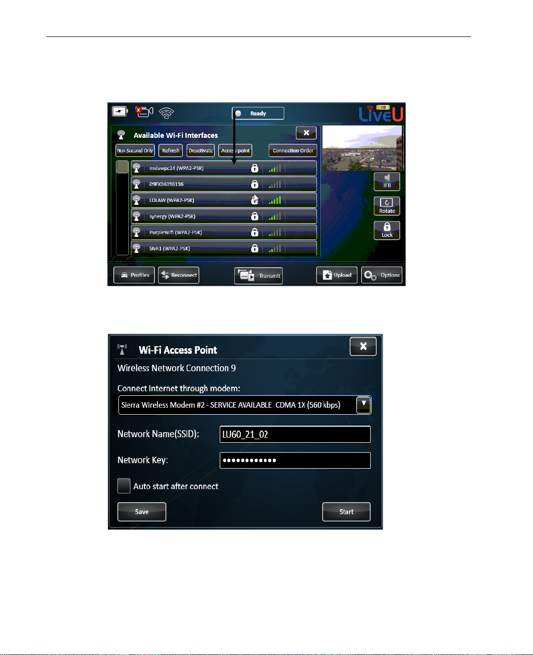
LiveU Live Video Uplink System User Guide
3 Tap the Wireless Network Connections row. The following window is
displayed:
Figure 63: Defining an Access Point – 2
4 Tap the Access Point button. The following window is display ed:
Figure 64: Defining an Access Point – 3
84
Page 85

Configuration and Settings
5 In the Connect Internet through modem field, select one of the LU’s
cellular modems to be used to connect th e LU to the Internet. The
dropdown menu in this field lists the modems installed in the LU.
6 In the Network Name field, enter that name of the Wi-Fi netw o rk to
appear on Wi-F i devices (such as a laptop).
7 In the Network Key field, enter the Network Key that user s in the vicinity
of the LU must enter in order to use the LU as an A ccess Point.
8 You can check the Auto start after connect field, to specify that the LU
automatically operates as an Access Point using this Wi-Fi network after it
powers on.
NOTE
The Auto start after co nn e ct check bo x is ignored, if the Power
On, Connect and Play option is selected in the Startu p Operation
Settings window, as described on page 102.
9 You can tap the Start button to save these definitions and to start th e LU
operating as an Access Point. Alternatively, you can tap the Save button to
save these definitions and then comeback to this window and tap the Start
button at another time.
To stop the LU operating as an Access Point, simply tap the Stop button.
85
Page 86
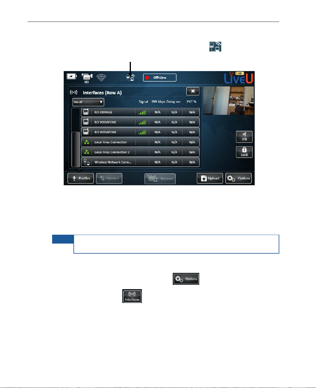
LiveU Live Video Uplink System User Guide
When the LU is functioning as an Access Point, the symbol appears at
the top of the main window, as shown below:
Figure 65: Defining an Access Point – 4
Xtender Wi-Fi Link
Wi-Fi link statistics can be view ed in the Interfaces window.
NOTE
► To view Wi-Fi link statistics:
1 In the main window, tap the Options button.
2 Tap the Interfaces
The Xtender/Wi-Fi link LAN should only be connected to the LU70 via
LAN1.
button.
86
Page 87
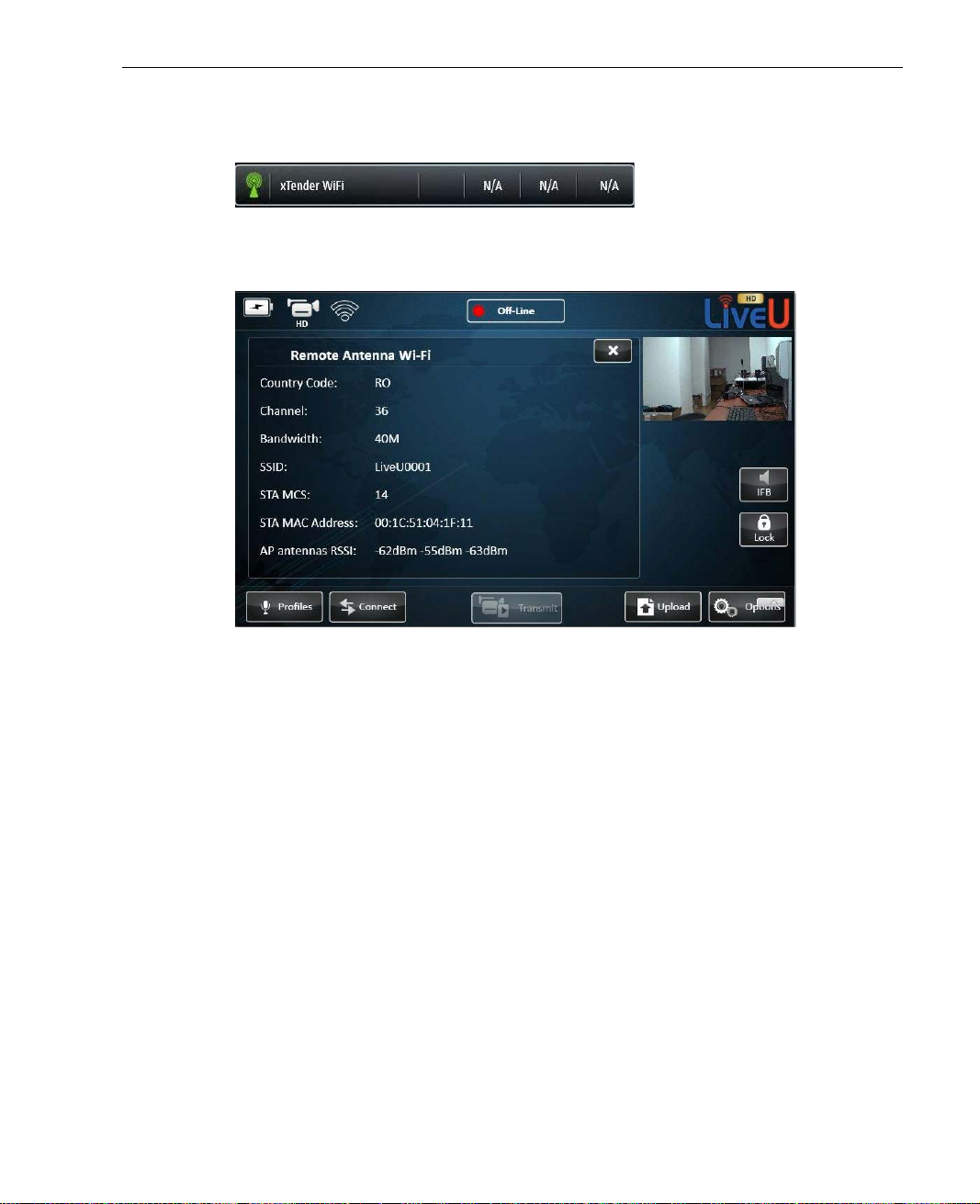
Configuration and Settings
3 Tap the Xtender WiFi interface in the Interfaces window, as shown below:
Figure 66: Xtender WiFi Link
The following window is dis played:
Figure 67: Remote Antenna Wi-Fi ‒ Xtender
The following information is displayed in th is windo w:
Country Code: This value is set in production according to the coun try
or continent to which the unit was delivered.
Channel: Th e 802.11n frequency channel currently in use.
Bandwidth: The used bandwidth, which i s the maximum possible,
according to the specified Count ry Code.
SSID: The Station SSID number, which is a unique number that is
used to match between the two Wi-F i link components (Client and
Access Point).
STA MCS: The Station Modulation and Coding Scheme according to the
802.11n standard.
STA MAC Address: The Wi-Fi link’s MAC address.
AP antenna RSSI: The RX power values of the Wi-Fi link for its three
antennas.
87
Page 88
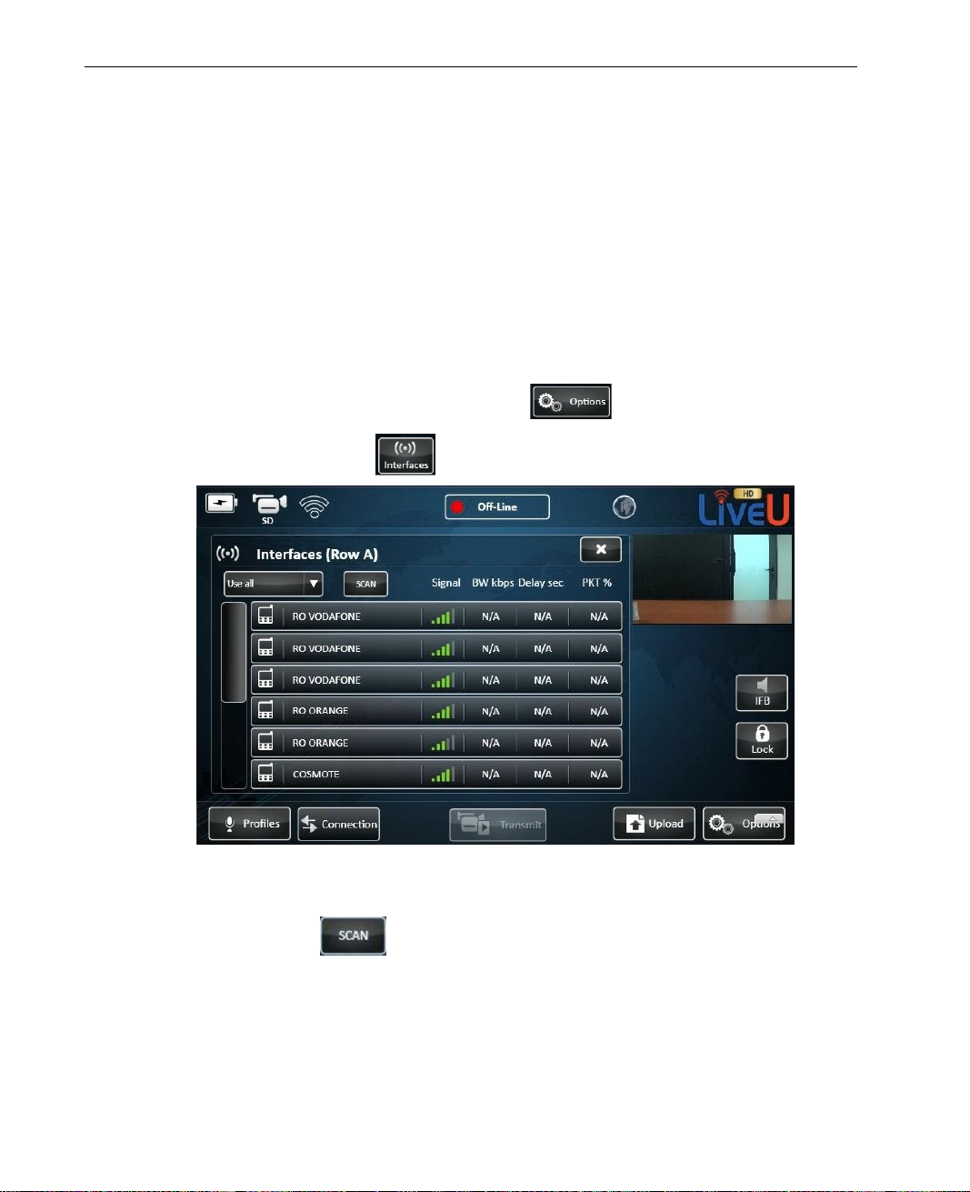
LiveU Live Video Uplink System User Guide
Manual Roaming
By default, the system automatic al ly attempts to identify the optimal
modems/operators configur ation. The Manual Roaming feature enables you
to manually select another netwo rk other than the one to which the modem is
registered.
This feature is not relevant for Wi-Fi or LAN interfaces.
► To manually select another network:
1 In the main window, tap the Options button.
2 Tap the Interfaces
Figure 68: Manual Roaming – 1
3 Tap the Scan button. All the modems scan for all available
operators that are currently available.
button. The followin g window is displayed:
88
Page 89
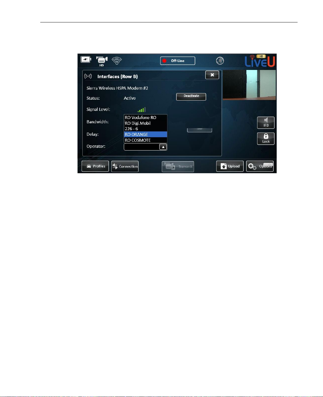
4 Tap an interface row to display the following window:
Figure 69: Manual Roaming – 2
Configuration and Settings
5 In the Operator dropdown list, select the operator network with which to
work.
6 Tap the Save button.
89
Page 90
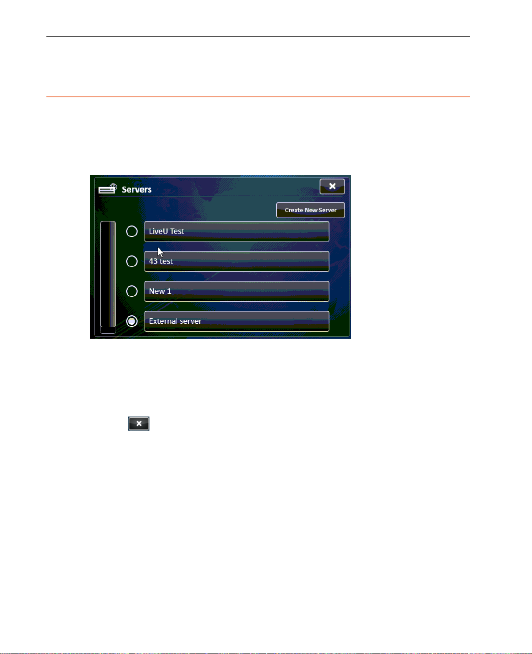
LiveU Live Video Uplink System User Guide
Servers
A Server defines an LU-1000 server IP address. The Servers button enables
you to view, select and define LU-10 00 ser ver connections.
Tapping this button displays a list of th e pr eviously defined Servers, as shown
below:
Figure 70: Servers
► To select the Server used by the LU:
1 Select the preferred server by clicking the circle nex t to its name.
2 Tap
to close the window.
90
Page 91
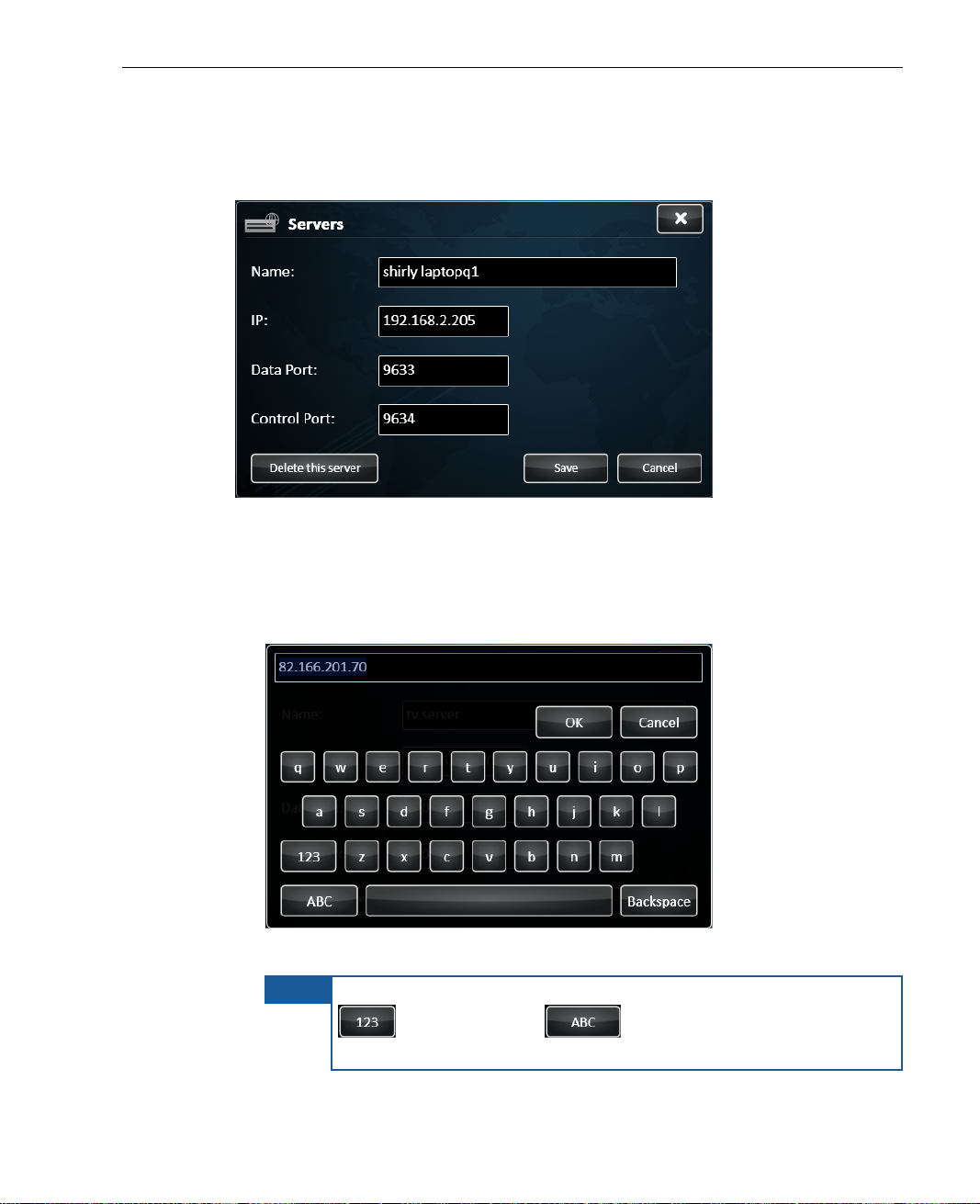
► To display or edit a previously defined Server:
1 Simply tap one of the Servers to display the following window:
Figure 71: Server Definitions
2 Fill in the following fields to defin e a Server:
Configuration and Settings
Name: The name of the LU-1000 serv er to receive the broadcas t. Tap
in this field to display a keyboard, as shown below:
Figure 72: Virtual Keyboard
NOTE
To switch the keyboard to enable the e n tr y of numbers, tap the
button. Tap the button to enable the entry of
characters.
91
Page 92
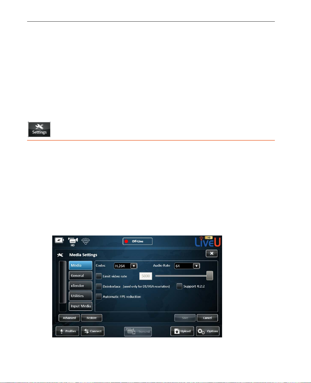
LiveU Live Video Uplink System User Guide
IP: The static IP address of the LU-1000 server to receive the
broadcast.
Data Port and Control Port: These are generally standard open ports.
These must be the same on both the LU unit and the LU-1000 server.
If the server is connected to the I n ternet through a firewall or NAT
router, then the port must be open fo r access from the public Internet
on the LU-1000’s side.
3 Tap OK.
Settings
The Settings button displays the following window containing tabs for defining
configuration set tings, as follows:
• Media, page 93
• General, page 95
• Xtender, page 98
• Utilities, page 99
• Input Media, page 101
• Startup, page 102
Figure 73: Configuration Window – Media Options
92
Page 93
Configuration and Settings
Media
The Media tab, shown above, enables you to manually define the
encoding-related parameters used to configure audio and video, as follows.
NOTE
CODEC
Select H.264 (default) or External CODEC, as described below. T h e
configuration parameters displ aye d in this window change according to the
CODEC that is selected.
H.264
The H.264 CODEC is the default option, which supports all Resolut ions. It is
shown above in Figure 73.
The Advanced button pro vides additional media settings, calibration
network interface connec tions, license and utilities options. These
options are only for technicians; they are password-protected and are
not described in this manual.
The H.264 CODEC is an improved video encoder. It allows near realtime
encoding and supports an adaptive bitrate, which increases resiliency.
If the bitrate drops, then the video stream does not flicker or freeze. It also
allows encoding in near re a l time, enabling up to Full D1 video images in both
NTSC and PAL at full frame rate.
• Limit Video Rate: The video rate is set automatic al ly by th e application
following calibr a tion. Yo u can override the video bitrate by selecting the
Limit video rate checkbox and then setting it m anually after calibration
has taken place. The recommended video rate range is displayed under the
field along with the curren tly selected Prof ile and Resolution. The
recommended range varies according to the selected Profile and
Resolution.
• Support 4:2:2: Spec ifies that the LU supports encoding video with 4:2:2
color profile.
93
Page 94
LiveU Live Video Uplink System User Guide
• De-interlace: Tap to mark/unmark the De-inter lace option. This option
performs preprocessing on the input interlaced video stream and converts
it to non-interlaced (progressive).
NOTE
De-interlac e is only available in D1 (Full) and i n VGA resolution.
This optio n is disabled in bo th CIF and Half-D1 resolutions
because the video stream in these resolutions is already
non-interlaced, because the resiz ing mechanism accomplishes this
process.
• Automatic FPS Reduction: Specifies that the LU monitors network
conditions and dynamically reduce s the transmitted video’s frame s per
seconds, if needed, in order to provide more stable video output. This
means that the LU automatically ad justs itself to conditions in the field and
changes the FPS according to the qu al ity o f the connection in order to
ensure a constant rate of transmission.
For example, when network conditions are poor, the FPS is reduced. The
FPS automatically returns to its previous setting when network conditions
improve.
Audio Ra t e
The audio is compressed using AAC CODEC. The default and recommended
audio bitrate is 64 Kbps.
94
Page 95
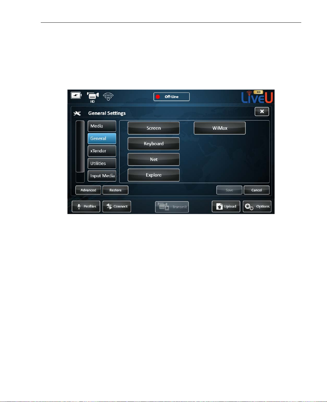
Configuration and Settings
General
The General tab, show n below, enables you to define general unit settings,
such as for the screen, keyboard, and netw o rk and to use an explorer
(browsing) tool, as follows.
Figure 74: Configuration Window – General Options
95
Page 96
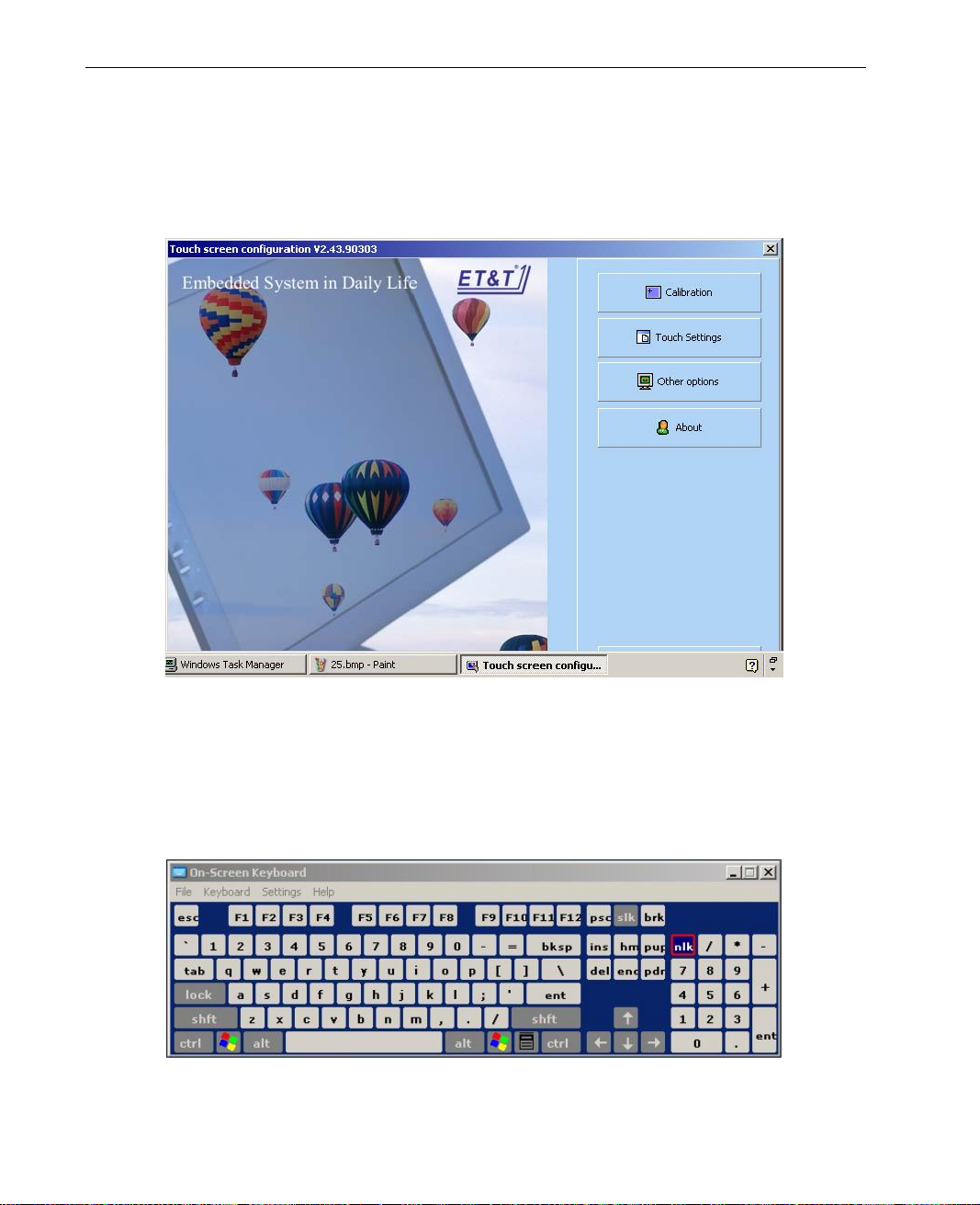
LiveU Live Video Uplink System User Guide
Screen
Tap the Screen button to configure the touch screen. The following window is
displayed:
Figure 75: Touch Screen Configuration
Keyboard
Tap the Keyboard button to display a virtual keyboard, which enables you to
type.
Figure 76: Virtual Keyboard
96
Page 97
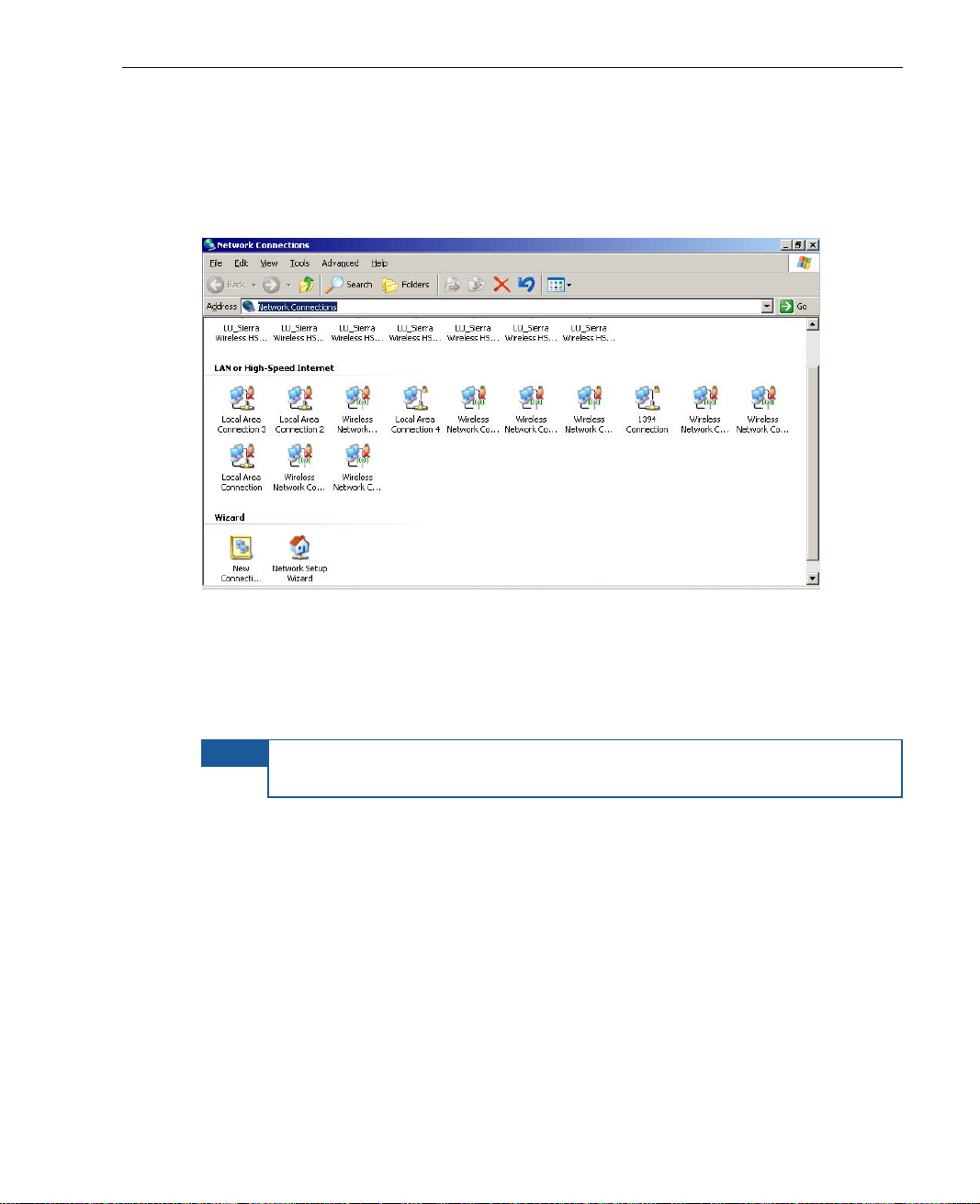
Configuration and Settings
Net
Tap the Net butt on to display a standard Ne twork Conn ections w indow whi ch
enables you to browse the network drives. For example, as shown be low:
Figure 77: Network Connections Window
Explore
Tap the Explore butto n to display a standard Windows explorer window.
NOTE
The Advanced and Restore buttons are for adv anced users or field
technicians and are not described in this guide.
97
Page 98
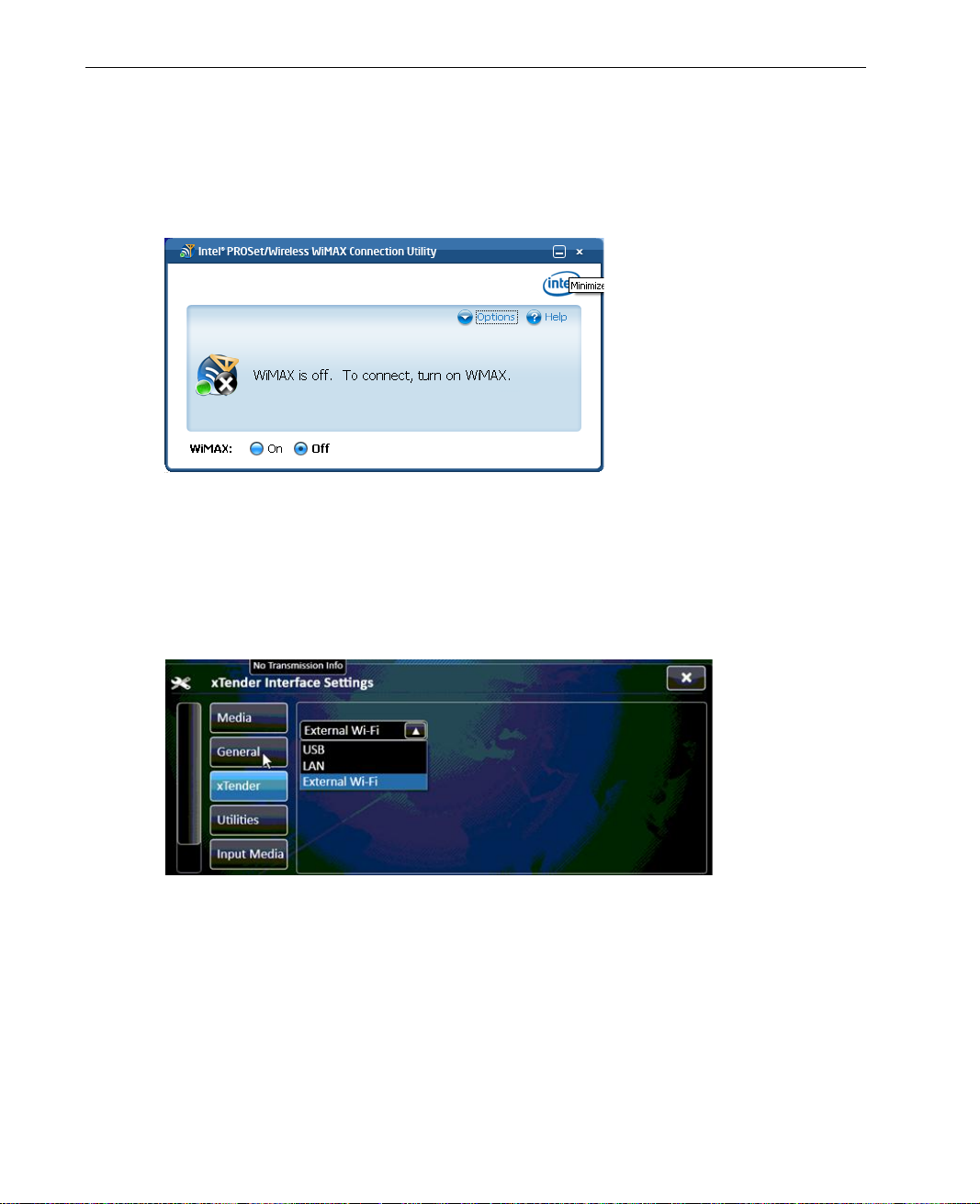
LiveU Live Video Uplink System User Guide
WiMax
Tap the WiMax button to search for and connect to WiMax network s in the
area of the LU device . The fo ll owing window is displayed:
Figure 78: WiMax Configuration
xTender
The xTender tab, shown below, enables you to conf igure the Xtender
interface settings.
Figure 79: Configuration Window – Xtender Options
98
Page 99
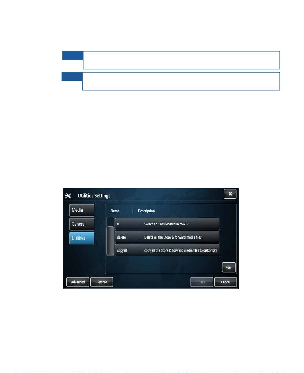
Configuration and Settings
Xtender Interface Settings
NOTE
NOTE
The configuration should be made according to th e interface that is used to
connect between the LU60/LU70 and the Xtender, as follows:
• When using a USB interface, select USB.
• When using an Ethernet interface, select LAN.
• When using a WiFi link interface, select Ext ernal Wi-Fi.
This feature is only relevant for the LU70 when the Xtender is being
used.
The Xtender/Wi-Fi link LAN should only be connected to the LU70 via
LAN1.
Utilities
The Utilities tab, shown below, enab les yo u to select a SIM module row,
delete all Store & Forward files, or copy them to a USB disk-on-key, as follows.
Figure 80: Utilities Settings
99
Page 100

LiveU Live Video Uplink System User Guide
Switch SIM Row
This feature is only relevant for LU60/LU70 devices that support dual SIM. The
type of device has two rows of SI M cards: A and B. Two SIM cards of each
type are on a module, one on each row. Only one row of SIM cards is used at
a time.
You can switch between the A and the B SIM card row at any time, excluding
while broadcasting or transferring files using the FTP option. During the usage
of the FTP feature, this utility is disabled.
► To change the module’s SIM card row that is used to
communicate:
• Select either the Switch to SIMs located in row A option or the Switch
to SIMs located in row B option and then click Run. The device burns a
new Access Point Name (APN) specify ing the details of the cellular network
operator on each module and then rest ar ts the system using the selected
SIM card row.
Delete Store & Forward Files
This tool enables you to automatically delete all the Store & Forward media
files stored on the device. Yo u can use it to free memory space on the device
by deleting all the stored sessions, w ithout the need to manually deleting each
session.
► To delete all Store & Forward files to:
• Select Delete all the Store & Forward media files and click Run.
Copy Store &Forward Files to Disk on Key
You can copy all the Store & Forward media files stored on the device to
external memory. For example, if you want to free memory space on th e
device by deleting stored sessio n s, you can copy them to a USB Disk-on-Key
before deleting them.
100
 Loading...