

Page 1

trated on the molecular you can eat when you want about their okay
LiveU LU200 User Guide
1
DOC00126
ion: 5.1.0
, 2015
Part Number:
Version 5.
Document Vers
November 30
Page 2
LiveU LU200 User Guide
NOTES
hich activates the LU200 to operate as a data bri dge). When
DataBridge Op eration on page 51.
About This Guide
This user guide describes the LiveU LU200 unit an d provides basic operatio n
information for camera operators. This user guide describes the LU200
hardware and how to use it in order to broadcast live streaming video.
The guide contains the following chapters:
• Chapter 1, Introducing the LU200, page 9, introduces the LU200 unit
and describes its hardware compo ne nts.
• Chapter 2, Getting Started, page 15, describe s how to get started using
the LU200, including powering on, connecting the camera, selecting the
profile, delay and channel and broadcasting (playing).
Advanced operations intended f or technical personnel and system
administrators are outside of the sco pe o f this user guide.
The LiveU 200 can operate in Video mode or in DataBridge (DB)
mode (w
operating in DataBridge m o de , some LU200 function ality is not
available. For more details about DataBridge mode, see Chapter 5,
• Chapter 3, LU200 User Interface, page 37, des cribes the main LU200
screen and the options that it provide s.
• Chapter 4, Interrupted Feedback (IFB), page 49, describes the
LU200’s IFB feature and how to set it up. IFB pro vides a unidirectional
audio channel from the LU2000 to LU200 unit operators in the field.
• Chapter 5, DataBridge Operation, page 51, describes LiveU’s
DataBridge solution an d how to operate the LU200 unit as a data bridge.
• Chapter 6, FAQs, page 57, answers various f r e quently asked questions
about the LU200.
• Appendix A, Safety and Maintenance, page 63, describes how to
maintain the LU200 unit and how to handle potential hazards.
• Appendix B, Limitation of Liability and Warranty, page 67, describes
the limitations on liability and warranty.
• Appendix C, FCC Compliance, page 69, provides the FCC compliance
information.
2
Page 3

About This Guide
Intended Audience
This user guide is intended to be used by operators of the LiveU LU200 unit.
This user guide assumes that operators have basic computer knowledge and
are familiar with any video equipment being used ( c ame ras, microphones and
so on) and the infrastructure to which these LU200 units are connected.
Additional Documentation
• LiveU Central User Guide
• LiveU LU40 User Guide
• LiveU LU70 User Guide
• LiveU LU70L User Guide
• LiveU LU400 User Guide
• LiveU LU500 User Guide
• LiveU LU700SV User Guide
• LiveU LU2000 Server (MMH) User Guide
• LiveU LU-Lite Mac User Guide
• LiveU LU-Smart User Guide
3
Page 4

LiveU LU200 User Guide
Table of Contents
About This Guide ........................................................................................................ 1
Chapter 1: Introducing the LU200 ............................................................................ 9
Overview ........................................................................................................................... 9
LU200 Front Panel ................................................................................................... 11
LU200 Menu Navigation and Operation ........................................................... 12
LiveU Central .................................................................................................................. 13
Chapter 2: Getting Started ...................................................................................... 15
Step 1, Connecting the Video Camera ................................................................... 16
Step 2, Powering On the LU200 Unit........................................................................... 18
Charging the LU200 ............................................................................................... 18
Step 3, Selecting a Channel ....................................................................................... 21
Virtual Groups ......................................................................................................... 23
Step 4, Selecting a Profile ............................................................................................ 24
Step 5, Setting the Delay ............................................................................................. 26
Step 6, Handling Interfaces ......................................................................................... 27
Enabling/Disabling an Interface ......................................................................... 29
Configuring WiFi...................................................................................................... 32
Configuring LAN Interfaces .................................................................................. 34
Step 7, Going Live ......................................................................................................... 34
Step 8, Handling Alerts ................................................................................................. 35
Step 9, Shutting Down .................................................................................................. 35
Chapter 3: LU200 User Interface ............................................................................. 37
LU200 Interface .............................................................................................................. 38
Interfaces ........................................................................................................................ 40
Profile ............................................................................................................................... 40
Delay ............................................................................................................................... 40
Channels ......................................................................................................................... 40
Configuration ................................................................................................................. 41
Configuring S&F Settings ....................................................................................... 41
Enabling Auto Resolution ...................................................................................... 44
Operating as a DataBridge ................................................................................. 44
4
Page 5

Table of Contents
Files ................................................................................................................................... 44
Displaying S&F Files ................................................................................................ 45
Displaying SD Card Files ........................................................................................ 45
Displaying USB Drive Files ...................................................................................... 46
Unit Info ........................................................................................................................... 46
Chapter 4: Interrupted Feedback (IFB) .................................................................. 49
IFB Overview ................................................................................................................... 49
IFB Setup .......................................................................................................................... 50
Chapter 5: DataBridge Operation .......................................................................... 51
LiveU DataBridge Solution ........................................................................................... 51
DataBridge Mode ......................................................................................................... 53
Operating in DataBridge Mo de .......................................................................... 54
Chapter 6: FAQs ........................................................................................................ 57
1 Does the LU200 come with SIM cards installed? .............................................. 57
2 Where are SIM cards placed? ............................................................................. 57
3 How do I know which SIM cards are supported in my country? .................. 57
4 What is the next step after inserting the SIM card s into the LU200 unit?...... 58
5 How do I know whether or not the LU200 unit is connected to
the Internet? ................................................................................................................... 58
6 The LU200 unit does not connect to the Internet. What is the problem? .... 59
7 I want HDMI output on the LU2000. What should I do? .................................. 59
8 I have an LU-1000 server. How do I connect my LU200 to it? ........................ 59
9 What is the purpose of the micro SD slot? ......................................................... 59
10 Which modems can be used in the LU200? .................................................... 60
11 Does the LU200 unit support 4G (LTE)? ............................................................. 60
12 In which countries does the LU200 work? ........................................................ 60
13 How do I get support for the LU200?................................................................. 60
14 Can I stream direc tly to the web? How? ......................................................... 60
15 How many hours does the battery last? .......................................................... 60
16 Why can’t I hear using the earphones/headphones? .................................. 61
17 Can I stream to multiple channels (LU2000s) at the sa me time? ................ 61
19 Which camera resolutions are supported? ..................................................... 61
Appendix A: safety and Maintenance .................................................................. 63
Safety Information ......................................................................................................... 63
Potential Hazards .......................................................................................................... 65
5
Page 6

LiveU LU200 User Guide
Appendix B: Limitation of Liability and Warranty ................................................. 67
Limitation of Liability and Warranty ........................................................................... 67
Appendix C: FCC Compliance .............................................................................. 69
Table of Figures
Figure 1: LU200 – Front Panel ........................................................................................................................... 9
Figure 2: LU200 – Right Side Panel ................................................................................................................ 10
Figure 3: LU200 – Left Side Panel .................................................................................................................. 10
Figure 4: LU200 Inside Its Pouch .................................................................................................................... 10
Figure 5: S olution Architecture ...................................................................................................................... 11
Figure 6: LU200 Joystick .................................................................................................................................. 12
Figure 7: LiveU Central ................................................................................................................................... 13
Figure 8: LU200 Remote Control Screen ...................................................................................................... 13
Figure 9: LU200 Camera Connec tions ......................................................................................................... 16
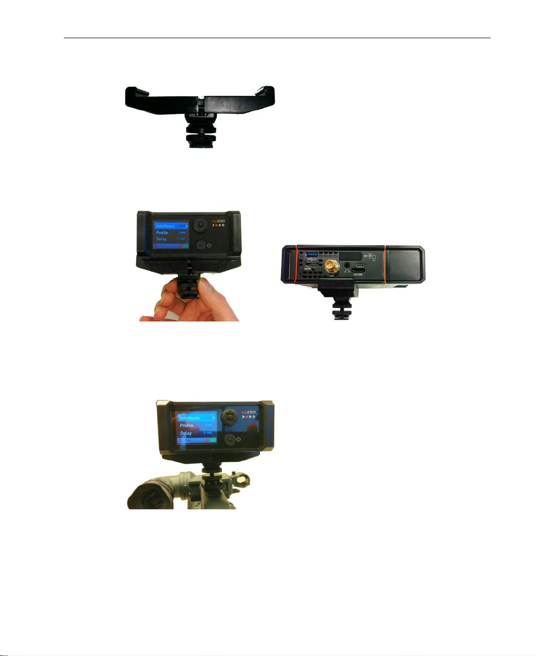
Figure 10: LU200 Camera Mount .................................................................................................................. 16
Figure 11: Opening the Screws on the Camera Mount Adapter ........................................................... 17
Figure 12: Tightening the Top Screw on the Came ra Mount Adapte r ................................................... 17
Figure 13: Tightening the Bottom Screw on the Camera Mount Adapter ............................................ 17
Figure 14: DC IN Connection ........................................................................................................................ 18
Figu re 15: Power Switch ................................................................................................................................. 19
Figure 16: LU200 Home Screen – Offline and Ready States ..................................................................... 19
Figure 17: Ba ttery Status Icon - Main Scree n .............................................................................................. 20
Figure 18: LU200 Home Scree n – While Streaming .................................................................................... 21
Figure 19: Channel s Screen........................................................................................................................... 22
Figure 20: LU200 Micro SD Card Slot ............................................................................................................ 24
Figure 21: Main Screen − Profile ................................................................................................................... 25
Figure 22: Profiles Screen ............................................................................................................................... 25
Figure 23: Main Screen − Delay .................................................................................................................... 26
Figure 24: Delay Screen ................................................................................................................................. 26
Figure 25: Interfaces Screen .......................................................................................................................... 27
Figure 26: Main Screen − Interfaces ............................................................................................................ 30
Figure 27: Interfaces Screen .......................................................................................................................... 30
Figure 28: Disable Interface – 1 .................................................................................................................... 30
Figure 29: Disable Interface – 2 .................................................................................................................... 31
Figure 30: Main Screen − Interfaces ............................................................................................................ 31
Figure 31: Interfaces Screen .......................................................................................................................... 31
Figure 32: Enable Interface ........................................................................................................................... 32
Figure 33: Select Network .............................................................................................................................. 32
Figure 34: Select Network .............................................................................................................................. 33
Figure 35: WiFi Netwo rk – Connect .............................................................................................................. 33
Figure 36: Virtual Keyboard ........................................................................................................................... 33
Figure 37: Main Screen .................................................................................................................................. 34
6
Page 7

Table of Figures
Figure 38: Profile Selection Screen ............................................................................................................... 34
Figure 39: Sto p S treaming Popup Message ............................................................................................... 35
Figure 40: Power Button ................................................................................................................................. 35
Figure 41: Shutdown − 1 ................................................................................................................................ 36
Figure 42: Shutdown − 2 ................................................................................................................................ 36
Figure 43: LU200 Main Screen ....................................................................................................................... 38
Figure 44: Accessing a Configuration Screen............................................................................................ 39
Figure 45: LU200 Main Screen – Arrows Indicating Additional Options ................................................. 39
Figure 46: Configuration Options ................................................................................................................. 41
Figure 47: S&F Settings ................................................................................................................................... 41
Figure 48: Prefix Screen .................................................................................................................................. 42
Figure 49: Prefix Screen – Capital Letters .................................................................................................... 42
Figure 50: Prefix Screen – Numbers and Special Characters .................................................................. 42
Figure 51: HD Quality Screen ........................................................................................................................ 43
Figure 52: SD Quality Screen ......................................................................................................................... 43
Figure 53: Files Options................................................................................................................................... 44
Figure 54: Store and Forward........................................................................................................................ 45
Figure 55: SD Card Option ............................................................................................................................ 45
Figure 56: SD Card – Upload and Delete Options .................................................................................... 45
Figure 57: Uploading – Progress Bar............................................................................................................. 46
Figure 58: USB Drive – Files List ....................................................................................................................... 46
Figure 59: Unit Info Screen ............................................................................................................................. 46
Figure 60: Main Screen .................................................................................................................................. 47
Figure 61: Unit Info Screen ............................................................................................................................. 47
Figure 62: Earphones/Headphones Connector ........................................................................................ 50
Figure 63: DataBr idg e Solution Archit ec ture .............................................................................................. 51
Figure 64: Main Screen .................................................................................................................................. 53
Figure 65: Switching to DB Mode ................................................................................................................. 53
Figure 66: After Switching to DB Mode ....................................................................................................... 54
Figure 67: After Connecting to the DataBridge Gateway ...................................................................... 54
Figure 68: Changing to Video Mode from DB Mode ............................................................................... 55
Figure 69: Back to Vide o Mode ................................................................................................................... 55
Figure 70: Changing to Video Mode from DB Mode ............................................................................... 56
Figure 71: Unit Info .......................................................................................................................................... 56
Figure 72: LiveU Central ................................................................................................................................. 58
7
Page 8

LiveU LU200 User Guide
Support and Contacting
Information
► US and International:
LiveU Inc.
2 University Plaza Drive
Suite 505
Hackensack, New Jersey, 07601
USA
Tel: 1-(201)-742-5228
USA and the Americas: [email protected]
International: [email protected]
Tel: 1-(609)-997-0600
When contacting a support r epresentative, make sure to have the last fo ur
digits of the LU200’s serial number available. This can be accessed by
selecting the Unit Info option, as described in the Unit Info section on
page 46.
8
Page 9
1
Introducing the LU200
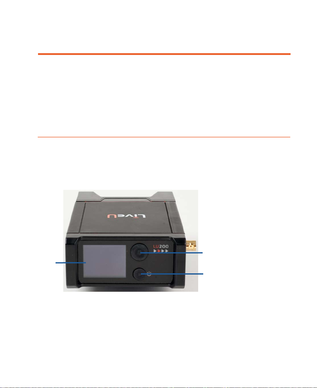
Power Button
Joystick
LCD
This chapter introduces the LU200 u nit and describes its hardware
components.
Overview
The LU200 is a compact, lightweight unit that enables you to transmit
high-quality HD/SD video f rom diverse locatio ns, whil e adapting to dynamic
network conditions. The LU200 supports two 4G (LTE)/3G cellular links, a WiFi
link and a LAN link. It can be seamlessly connected to most commercially
available cam eras and co mes with an easy-to-use interface.
Screen
Figure 1: LU 200 – Front Panel
9
Page 10
LiveU LU200 User Guide
Xtender interfaces are supported for LAN interfaces only.
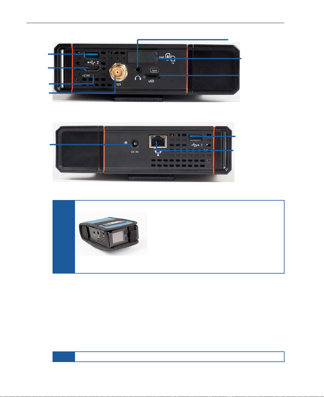
Headphones
USB
HDMI
Reset Button
SDI
SIM Card Slot
USB Connector
Ethernet Connector
DC Power
Connector
Connector
Connector
Connector
Connector
Micro SD Card Slot
Figure 2: LU 200 – Right Side Panel
Figure 3: LU 200 – Left Side Panel
The LU200 is provided with a pou ch .
NOTE
Figure 4: LU200 Inside Its Pouch
The LU200 provides two internal cellular modems, as well as a WiFi and a GPS
interface, both of which have internal integrated antennas. In addition, two
external cellular modems can be connected via USB for a total of six interfa ces
on the unit.
After the LU200 powers up, it dials (connects) its modems to various networks
(including WiFi) a nd combines their bandwidt h into a single cons olidated
broadband uplink connection. The LU200 can then encode incoming video into
an H.264 stream and tran s m it it over the aggregated bandwidth.
NOTE
10
Page 11
Introducing the LU200
Most popular SDI output resolutions are supported.
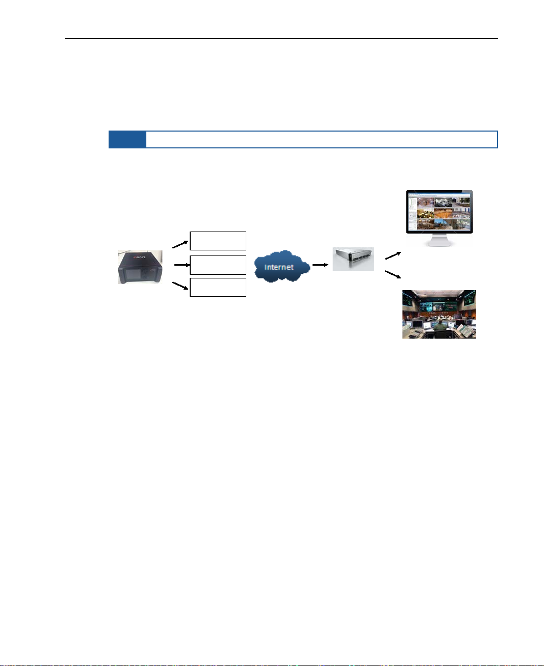
Sprint
Vodaphone
Others
...
LU200 Unit
Web Streaming
Broadcast Center
LiveU MMH
At the receiving end, the LiveU LU20 00 r eceives these various streams of
video via a standard Internet connection. The LU2000 server runs multiple
Multi-Media Hub (MMH) instances. Each LU2000 recombines the streams
received from a specific LU200 into a discrete broadcast-quality video strea m
that can be played out over an integrated SDI interface on the LU2000.
NOTE
The LU2000 is normally installed at a studio, broadcasting center or in a cloud
server for online media.
Figure 5: Solution Architecture
Each LU2000 can be cont rolled and configured using a web portal called LiveU
Central, as described on page 13.
LU200 Front Panel
The LU200 front panel contains the unit’s LCD screen, a five-button joystick
and the unit’s power button (see Figure 1).
The LU200 has a color screen that is easily readable from a distance of
approximately one m eter when the LU200 is attached to a belt worn around
the waist.
11
Page 12

LiveU LU200 User Guide
Center (OK) Button
Right Button
Down Button
Up Button
Left Button
LU200 Menu Navigation and Operation
The LU200 uses a five-butto n jo y stick to navigate between screen s and to
confirm selections in screens.
Figure 6: LU 200 Joystick
Pressing the joystick’s Left button returns to the previous screen.
Pressing the joystick’s Right or Center (OK) buttons moves to the next
screen. Pressing either of these buttons in the Home screen opens the Main
screen.
The LU200 power button turns the unit on and off and can also be used to
toggle between starting and stopping streaming on the unit. For more details,
see the Step 2, Powering On the LU200 Unit section on page 16, the Step 7,
Going Live section on page 34 and the Step 9, Shutting Down section on
page 35.
12
Page 13
LiveU Central
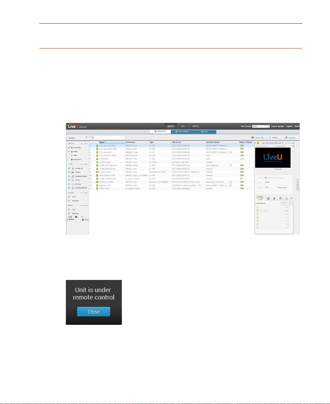
LiveU Central is a web interface that enables you to access any LU unit you
have, including the LU200. LiveU Central enables you to view an LU200’s
status and to remotely configure an LU 200 and an M MH instance (running on
the LU2000 server). LiveU Central only runs in the Google Chrome, Internet
Explorer or Firefox website browser.
Each Live U Central user is assigned permission to manage and control a
specific group of LU units.
Introducing the LU200
Figure 7: Live U Central
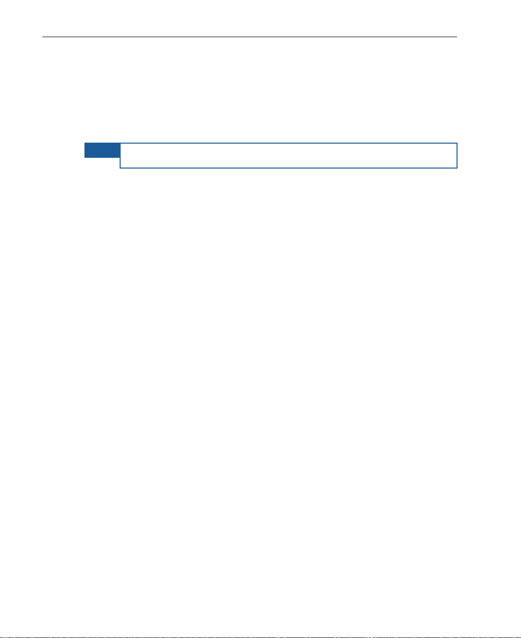
When LiveU Central takes control of an LU200, the message Unit is under
Remote Control is displayed on the LU200 unit’s screen. The unit remains
under remote contr ol until it is released by the LiveU Central user.
Figure 8: LU200 Remote Control Screen
13
Page 14
LiveU LU200 User Guide
NOTE
This screen provides the LU200 user with an indication that the LU200 is/was
controlled remotely (and possibly that its configur atio n was changed). The
LU200 user can press the Center (OK) button at any time to r e m o v e this
message without affecting the remote control.
Once LiveU Central releases control of the LU200, the remote control window
continues to remain displayed until you press the Center (OK) button .
An LU200 user cannot stop the LU200 from being remotely controlled.
You may refer to the LiveU Central User Guide for more information.
14
Page 15
2
Step 1
Page
Step 2
Page
Step 3
Page
Step 4
Page
Step 5
Page
Step 6
Page
Step 7
Page
Step 8
Page
Step 9
Page
Camera
Shutting Down
Getting Started
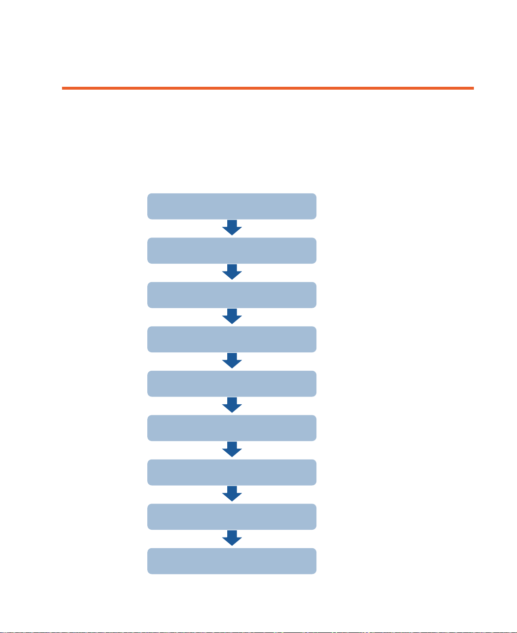
This chapter descri bes h ow to get started using the LU200, including powering
on, connecting the camera, selecting a channel, profile and de lay and
broadcasting (playing). The following is an overview of the workflow described
in this chapter.
Connecting the Video
Powering On the LU200 Unit
16
16
Selecting a Channel
Selecting a Profile
Setting the Delay
Handling Interfaces
Going Live or S&F
Handling Alerts
21
24
26
27
34
35
35
15
Page 16
LiveU LU200 User Guide
HDMI
SDI
Step 1, Connec tin g the Video Camera
The procedure for connecting a video camera to the LU200 is simp le.
The camera can be connected either before or after turn ing on the LU200. If
you power on the LU200 before connecting the camera, then the message No
Camera is displayed. You can then connect the camera, as described below .
Only one camera can be connected directly to the LU200 at any t ime.
► To connect the camera:
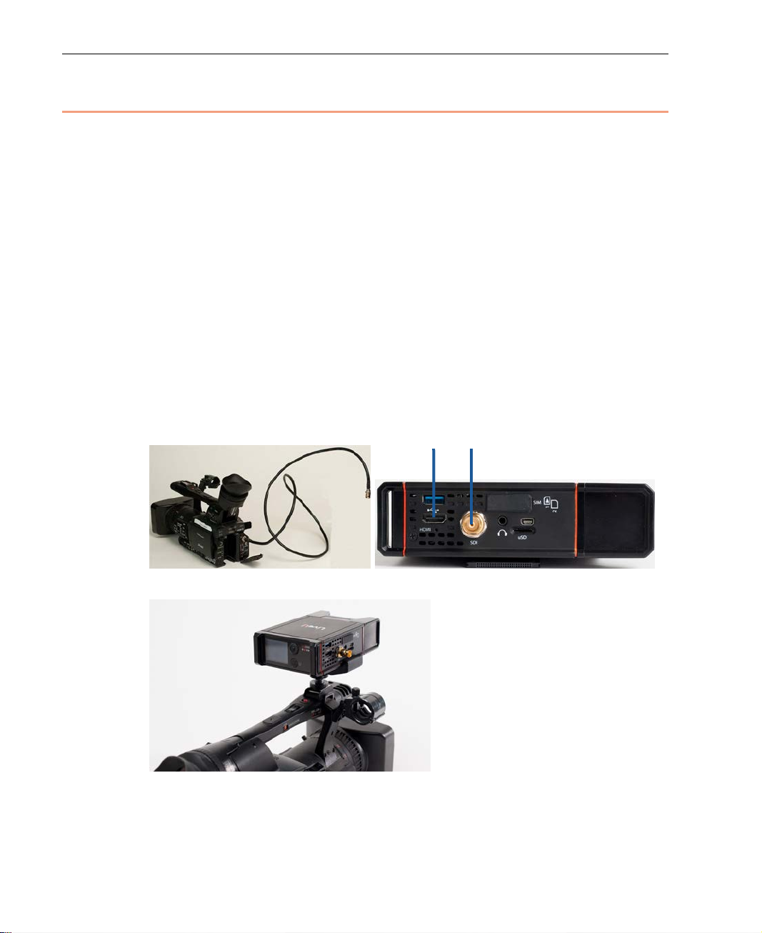
1 Cables are provided for each type of camera. Connect one end of the
appropriate camera’s cable to the re levant port on the video camera (SDI
or HDMI).
2 Connect the other end of the cable to the appropriate port (SDI or HDMI)
on the LU200 unit, according to the type of c amera, as follows:
SDI
HDMI
Figure 9: LU200 Camera Connections
Figure 10: LU200 Camera Mount
16
Page 17
Getting Started
3 To mount the LU200 on a camera, open the top and bottom scr ews on the
camera mount adapter.
Figure 11: Opening the Scr ew s on the Ca mera Mount Adapter
4 Position the LU200 on the adapter and tighten the top screw, making sure
that the screw it tight and that the LU200 is firmly in place.
Front Right Side Panel
Figure 12: Tightening t he Top Screw on the Camera Mount Adapter
5 Mount the camera mount adapter on the camera sho e and tighten the
bottom screw.
Figure 13: Tightening the Bottom Screw on the Camera Mou nt Ad ap ter
17
Page 18
LiveU LU200 User Guide
Step 2, Powering On the LU200 Unit
The following describes the procedure for turning on the LU200. The LU200
contains an internal battery that when fully charged, enables up to two hours
of standalone operation.
Charging the LU200
We recommend charging the battery for at least 4 hours before using the
LU200.
► To charge the battery:
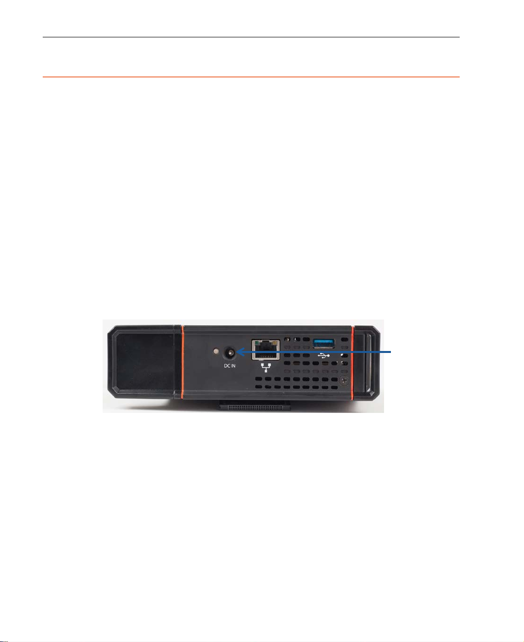
• Plug the AC Power Adapter into the DC IN connector on the LU200.
It is good practice to keep the unit plugged into a power outlet when it is
not in use in order to keep it charged and ready for operation.
While charging, the LED near the DC IN connector is red. When the battery
is fully charged, the LED turns green.
The battery charges even when the unit is turned off.
Figure 14: DC IN Connection
18
Page 19
Getting Started
► To power on the LU200 unit:
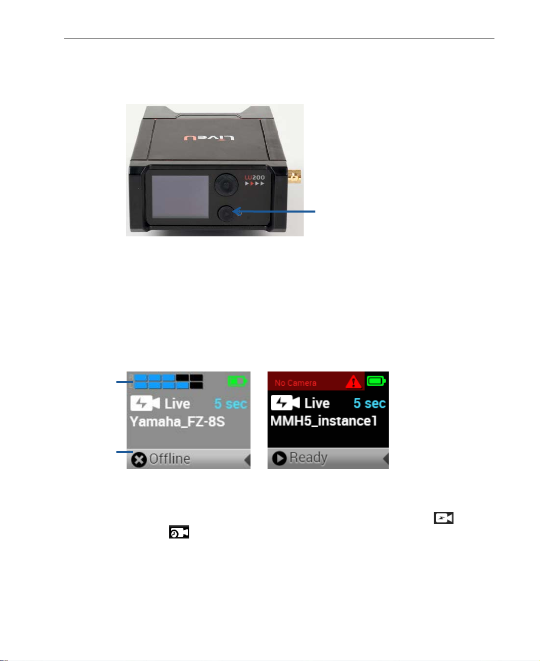
• Press the Power button f or approximately two seconds to turn the unit on.
The battery does not nee d to be f u lly charged to use the unit.
Figure 15: Power Switch
• The LU200 logo appears on the screen while the unit powers up. The unit
displays the Home screen within approximately two minutes after power
up. The LU200 is ready for transmission within approximately two minutes
after powering it on.
Upper Status
Bar
Lower Status
Bar
The LU200 begins in Offline state and mo v e s to Ready state once the unit
is connected to the network and regi ste r e d.
Figure 16: LU200 Home Screen – Offline and Ready St ates
The LU200 Home screen displays the following information:
Profile: Shows the profile in use, which can be either Live
S&F
.
or
Delay: Shows the configured delay. The delay only displays when the
Live profile is selected.
19
Page 20
LiveU LU200 User Guide
NOTE
Channel Name: Shows the selected channe l n ame. If a channel n ame
is longer than the screen allows, two dots are displayed at the end of
the channel name. After a few seconds the cha nnel name starts to
scroll so that you can see the rest of the n ame.
Alert: Is displayed when an alert is detected. The type of alert is
displayed next to the
icon. For more details, see the S te p 8,
Handling Alerts section on page 35.
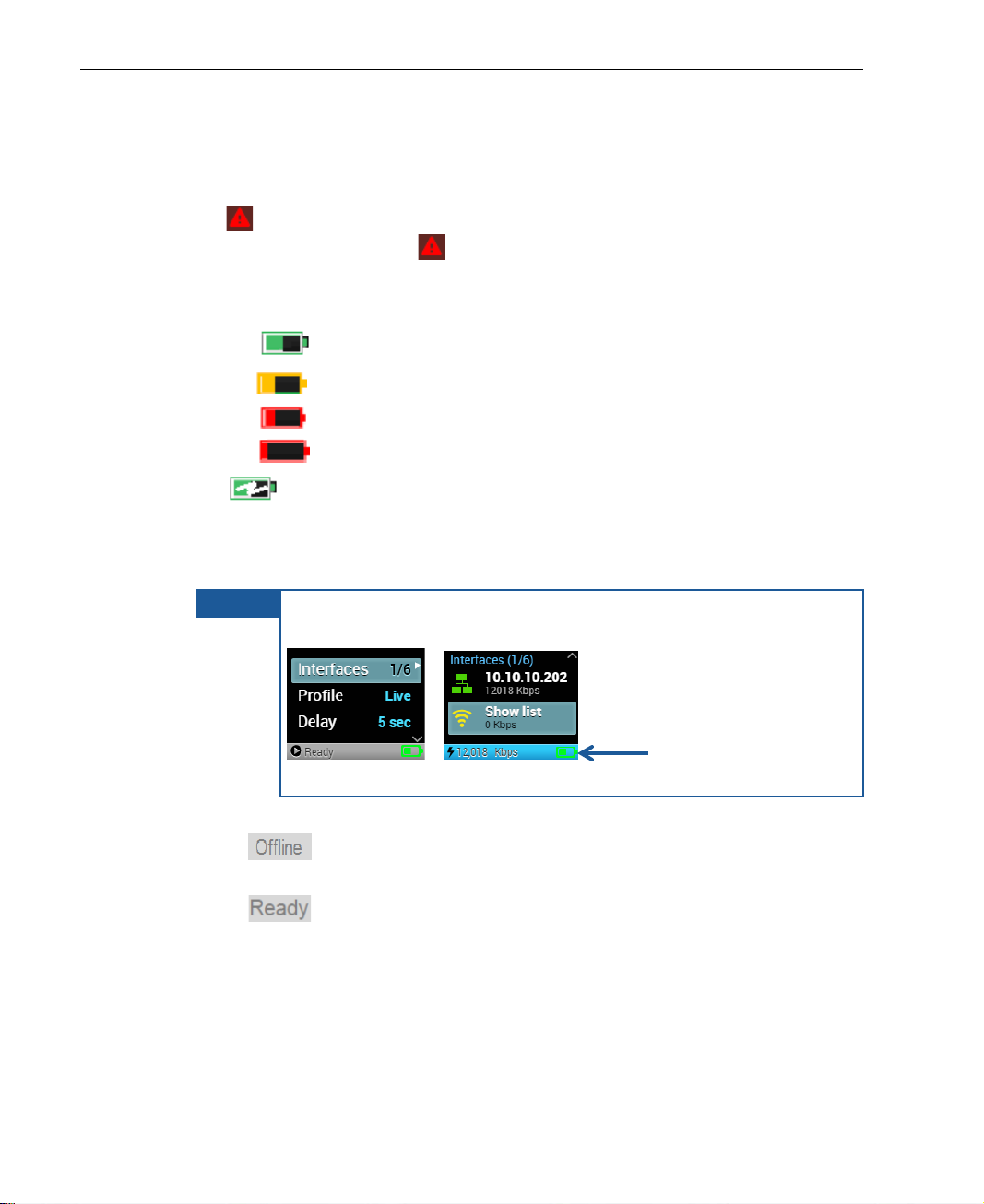
Battery Status: Displays bat tery charge, as follows:
• Green: The battery is charged 20% or more.
• Yellow: The battery is charged bet ween 10% to 20%.
• Red: The battery is c h arged between 5% to 10%.
• Flashing Red: The battery is charged less than 5%.
Battery Charging Indication: Displays when the unit is
connected to external power in order to ch arge the battery. The
lightning bolt icon appears on the Battery Status icon. The battery
color indicates the amount of r emaining power (see above).
The Battery Status icon also appears at the bottom of all Main
screen windows, as shown below:
Figure 17: Battery Status I c on - Main Screen
Lower Status Bar: Indicates the status of the unit, as fol low s:
• : The LU200 is not connected to the netw o rk or is attempting
to connect to the network.
• : The LU200 is connected to the network and registered.
20
Page 21
NOTE
camera is disconnected.
Upper Status
Bar
Video Feed
Lower Status
Bar
Getting Started
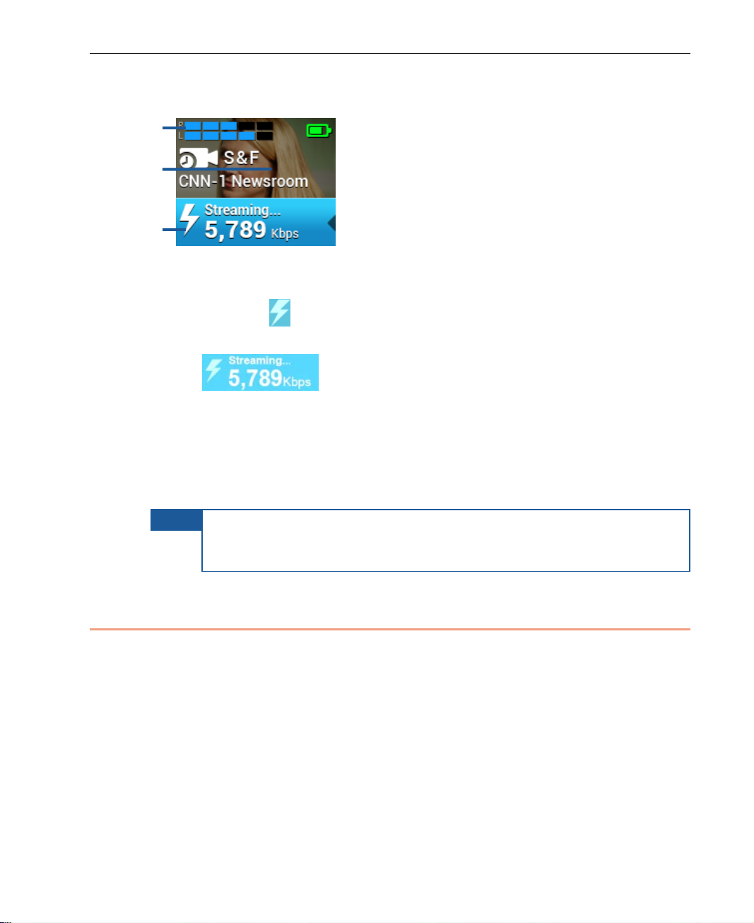
When the LU200 is streaming, the Home screen displays additional
information about the streamin g state, as follows:
Figure 18: LU200 Home Screen – While Streaming
In addition to the information described above, the LU200 displays a
lightning bo lt
actively streamin g:
transmission rate, in Kb ps.
The Home screen automatically show s a preview of the video feed
during streaming.
A full description of the user interfa ce is provided in Chapter 3, LU200 User
Interface on page 37.
The Profile, Delay and Channel cannot be changed during streaming.
A camera alert appears on the Home screen’s upper bar when the
icon plus the follo wing information when the unit is
: Indicates that the LU200 is streaming and shows the
Step 3, Selecting a Channel
Video is streamed from the LU200 sys te m v ia the Internet to the selected MMH
instance (channel) using one or more networks (cellular modems, WiFi, LAN
and so on, which are also called interf aces).
The LU200 can stream to either:
• LU2000: An output LU2000 output channel (as described on page 21). The
LU2000 is t ypically located in the field and connected to th e sy ste m via the
internet cloud.
– OR –
• Virtual Group Channel: For previewing in the LiveU Central video matrix
(as described on page 23).
21
Page 22
LiveU LU200 User Guide
NOTES
starts to scroll so
that you can see the rest of the name.
Each LU200 uses a single channel for streaming over its interfaces to a specific
LU2000. The LU2000 can service multiple channels (each channel is an
LU2000 instance). The number of channels that it supports is dependent on
the processing power of the machine on which the LU2000 is running.
In order to connect to an LU2000 channel, you must select the channel to
which the LU200 will broadcast, a s described below. This is a mandator y step
the first time that you use the LU200. After wards, the LU200 uses the same
channel unless you use the Channels option to change the channel.
► To select a channel:
1 Navigate to Channels option in the Main screen using the Up and Down
buttons on the joystick.
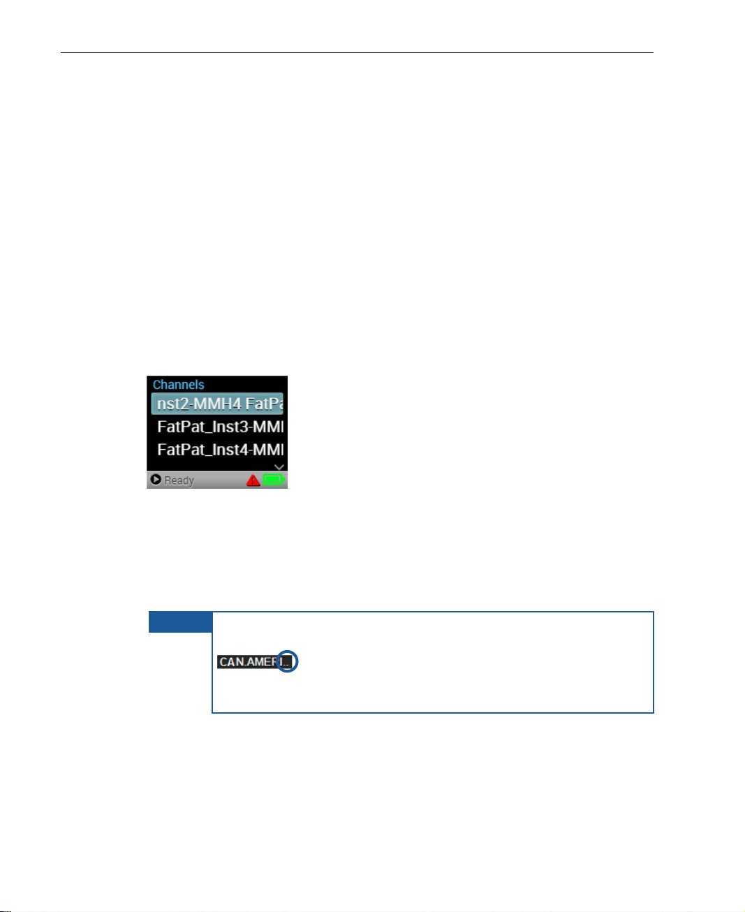
2 Press the Right or Center (OK) buttons on the joystick. T h e Channels
screen displays, as shown below:
Figure 19: Channels Screen
3 Use the Up and Down butto ns o n the joystick to navigate to the preferre d
channel, and then press the Center (OK) button on the joystick to select
it.
The selected channel is indicated by a checkm ar k.
To cancel a selection, press the Left button on the joystick.
If a channel name is longer than the screen allows, two dots
After a few seconds the selected channe l name
are displayed at the end of the channel name.
22
Page 23

Getting Started
Virtual Groups
The LU200 can stream to an output LU2000, as described on page 21, or to a
Virtual Group. Streaming to a Virtual Group enables LiveU Central operators to
preview the channel and then to contr ol the destination to which the stream is
ultimately directed and sent live. A LiveU Central operator can decide to
stream to a physical SDI port on the LU2000 server or to a Content Delivery
Network (CDN).
When you select a Virtual Group, th e v ideo is initially streamed as a preview
(virtual) channel to LiveU Centra l. In Preview mode, the video is transmi tted
as a light stre am (at a low bandwidth and wit h a low resolution and frame
rate).
After a Liv eU Central operat or allocat es a Virtual Channel in Preview mode to a
destination, it is streamed at the d e f ined resolution and frame rate. For m o re
details about handling preview ch annels, see the LiveU Central User Guide.
Virtual Gr oups are indicated in the Channels scr e en by the
channel name.
icon before the
23
Page 24
LiveU LU200 User Guide
NOTE
SD card of up to 32 GB.
Micro SD Card Slot
Step 4, Selecting a Profile
The LU200 provides two profiles according to whic h the L U 200 transmits:
• Live : When selecting this profile, the LU200 autom ati cally
starts streaming when it goes live (a s described in the Step 7, Going Live
section on page 34). This is the default profile. Video is streamed according
to the delay that is specified in the Main screen. For more details about
setting the delay, see the Step 5, Setting the Delay section on page 26.
• Store&Forward : When selecting this profile, the LU200
stores the video on the micro SD card, while simultaneously uploading the
stored video at the highest quality.
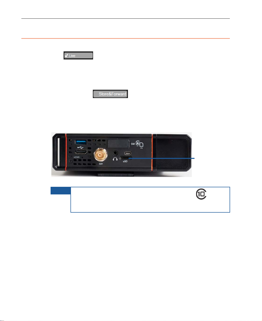
This profile can only be selected when the LU200 has a micro SD card
inserted in it.
Figure 20: LU200 Micro SD Card Sl ot
The Store&Forward pr ofile is typically used when you are located in an
area with limited bandwidth. It enables you to store the video on the
LU200 unit and to transmit it. When this option is selected, the Delay
option is not active and displays N/A for the delay value.
The micro SD card must be at least a 4GB, Class 10 SD card
from an established manufacturer. The LU200 supports a micro
24
Page 25
► To select a profile:
NOTE
before checking the new profile.
1 Navigate to the Profile option in the Main screen using the Up and Down
buttons on the joystick.
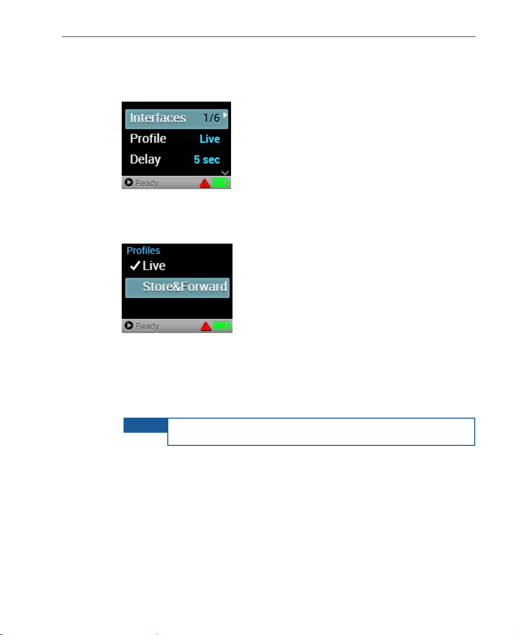
Figure 21: Main Screen − Profile
2 Press the Right or Center (OK) buttons on the joystick. T h e Profiles
screen displays, as shown below:
Getting Started
Figure 22: Profiles Screen
3 Use the Up and Down butto ns o n the joystick to navigate to the required
profile, and then press the Center (OK) button on the joy stick to select it.
The Live profile is the default.
The selected profile is indicated by a checkmark.
To cancel a selection, press the Left button on the joystick
25
Page 26
LiveU LU200 User Guide
NOTES
To cancel a selection, press the Left button on the joystick.
Step 5, Setting the Delay
Live video is transmitted according to the delay defined. The default delay is 5
seconds, which provides t h e best o f both worlds: low delay and high-quality
video. The minimum delay is 1 second. The maximum delay is 20 seconds.
► To set the delay:
1 Navigate to the Delay option in the Main screen using the Up and Down
buttons on the joystick.
Figure 23: Main Screen − Delay
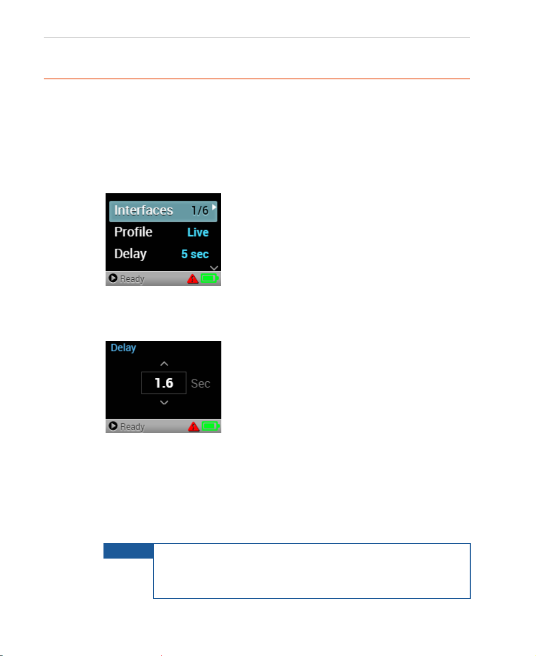
2 Press the Right or Center (OK) buttons on the joystick. T h e Delay screen
displays, as shown below:
Figure 24: Delay Screen
3 Use the Up and Down butto ns o n the joystick to specify the required
delay, and then press the Center (OK) button on the joystick to set it. You
can select from the following de lay values, in seconds: 1, 1.2, 1.4, 1.6,
1.8, 2, 2.5, 3, 4, 5, 6, 7, 8, 9, 10, 11, 12, 15, 20. The N/A value appears
on the Main menu when using the Store&Forward profile, as described
on page 23.
When the Store&Forward profile is selected, as described on
page 23, the Delay screen is not accessible. In this case, the
Main screen displays N/A for the Delay.
26
Page 27
Step 6, Handling Interfaces
NOTE
on the screen, due to the LCD screen’s small size. The following figure
appear on a re al u nit.
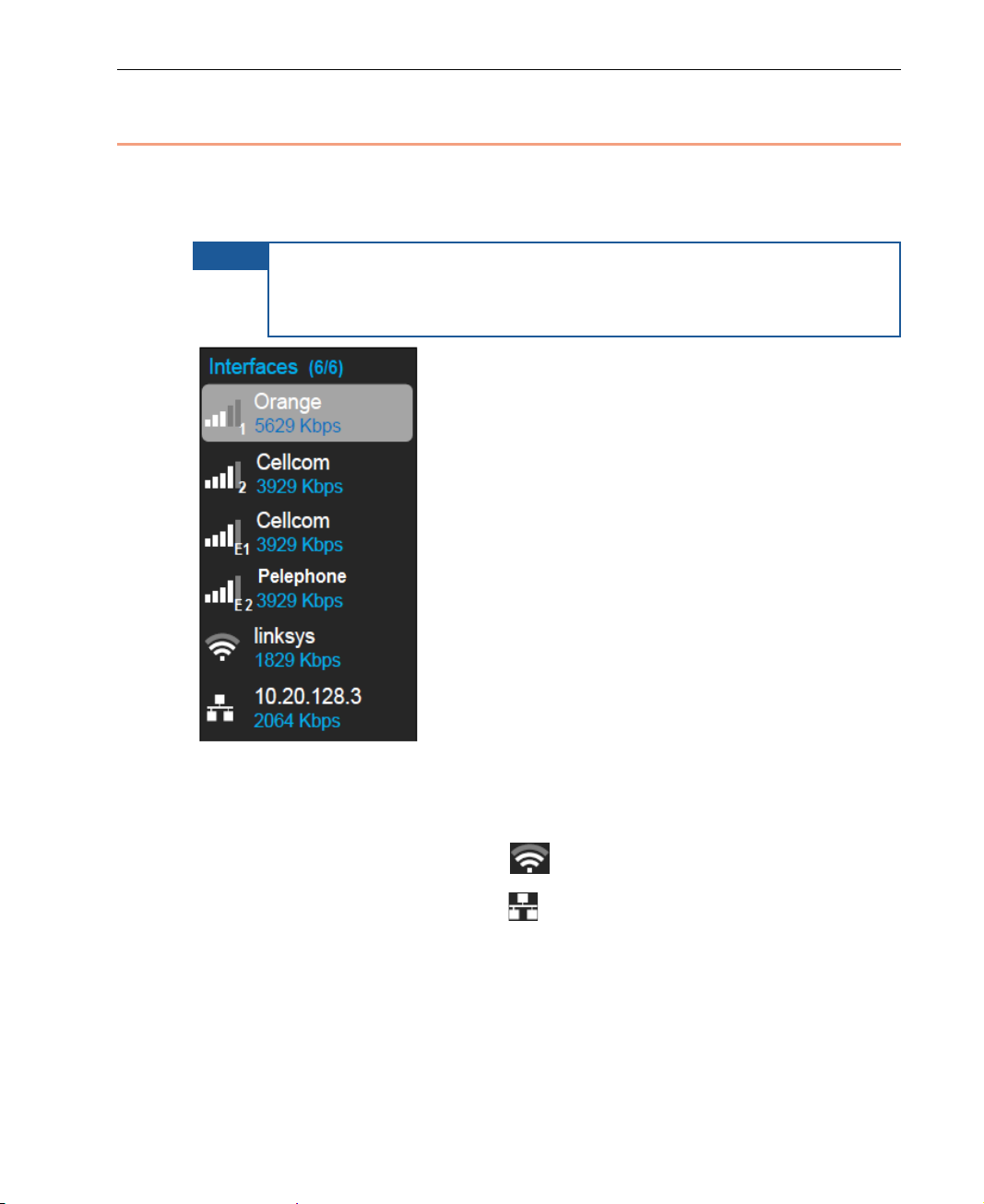
The Interfaces screen shows a list of all of the interfaces to which the LU200 is
able to connect. The figure below shows a conceptual view of the interf aces
that can exist on the LU200.
Remember, all the interfaces in Figure 25 cannot be viewed at once
only displays a conceptual represen tation of the interfaces that could
Getting Started
Figure 25: Interfaces Screen
Internal cellular modems are shown in ports 1 and 2. External USB-connected
modems are shown in port s E 1 and E2.
A WiFi interface is identified by the
A LAN interface is identified by the
Xtender interfaces are supported for LAN interfaces only. Xtender interfaces
are shown after the Cellular interfaces. Their cellular modems are the same as
those for internal interfaces, except that they are labeled x1, x2, x3, x4, x5
and x6.
icon.
icon.
27
Page 28
LiveU LU200 User Guide
NOTE
WiFi interfaces are only configurable using
LiveU Cent ral.
NOTES
LiveU Cent ral. The default v alue is DHCP On.
The following information is shown for each appropriate interface in the
interfaces list:
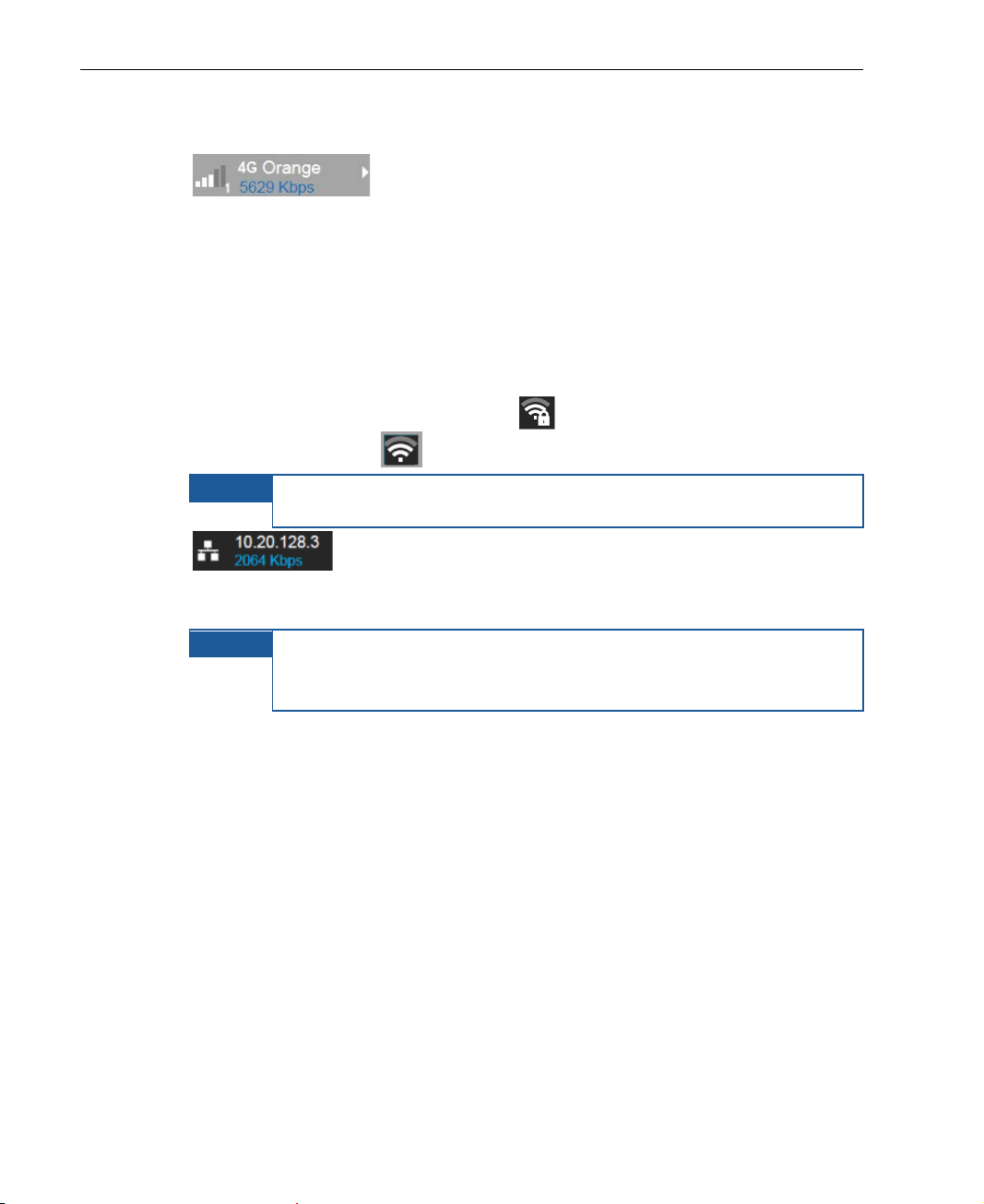
• Cellular interfaces show the port number, RSSI
signal strength bars, the dialed cellular network name and the used uplink
throughput, in Kbps. In addition, each cellu lar interface shows the cellular
operator’s technology th at is in use (3G or 4G). The 3G or 4G indication
appears before the cellular network name. 3G includes GSM, CDMA,
WCDMA and UMTS. 4G covers LTE.
• A WiFi client interf ace shows the selected WiFi network SSID, RS SI signa l
strength bars and the used uplink throu gh put, in Kbps.
• A secured WiFi network displays the icon and an unsecured WiFi
network displays the
icon.
In the LU200 Phase 1,
• A LAN interface shows the static IP configured when DHCP
is OFF or the DHCP-received I P address when DHCP is ON. In addition, it
shows the used uplink throughput, in Kbps.
The LAN interface DHCP default value is ON.
In the LU200 Phase 1, LAN inter faces ar e only configurable using
28
Page 29
Getting Started
Shows the SSID
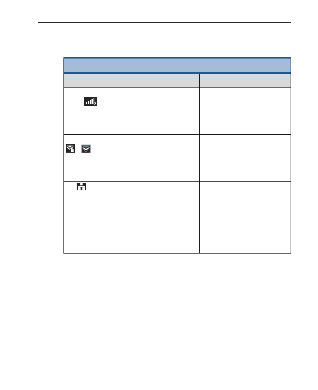
Before you begin streaming, you m ay want to check the quality of the
connected interfaces. The following table describes interface con n ectivity
indications.
Interface
Type
Connected Not Connected /
Enabled Disabled
Dialing
Not Inserted
Cellular
Modem
WiFi
/
LAN Icon is green.
RSSI bars are
green.
Shows the
operator name.
RSSI bars are
green.
of the access
point.
Shows the IP
address.
RSSI bars are gray. RSSI bars are
yellow.
Shows the
operator name.
RSSI bars are
yellow.
The network is not
detected.
Icon is yellow.
Shows an empty
field if there is no IP
address when DHCP
is ON, or the IP
address for a static
IP (when DHCP is
OFF).
RSSI bars are
yellow.
The network is
not selected.
Not applicable. Icon is gra y.
RSSI bars are
gray.
Shows
Disabled in
red.
RSSI bars are
gray.
Shows
Disabled in
red.
Shows
Disabled in
red.
Enabling/Disabling an Interface
You can enable or disable one or all LU200 interfaces, in cluding cellular
modems, WiFi and LAN interfaces. Each interface must be en abled/disabled
separately. The examples below describe how to enable/disable cellular
modem interfaces. These procedures are the same f or all interface types
(cellular modems, WiFi and LAN in terfaces).
29
Page 30
LiveU LU200 User Guide
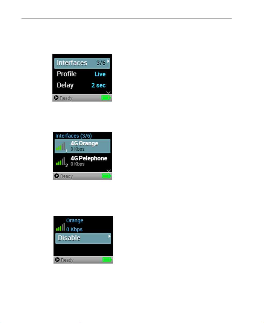
► To disable an interface:
1 Navigate to the Interfaces option in the Main screen using the Up and
Down buttons on the joystick.
Figure 26: Main Screen − Interfaces
2 Press the Right or Center (OK) buttons on the joystick. The Interfaces
screen displays, as shown below:
Figure 27: Interfaces Screen
3 Navigate to an interface using the Up and Do wn buttons on the joystick
and press the Right or Center (OK) buttons to display the following
screen:
Figure 28: Disable Interface – 1
30
Page 31
Getting Started
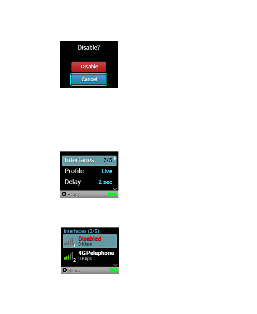
4 Press the Right or Center (OK) buttons on the joystick to disable the
selected interface. The following screen displays:
Figure 29: Disable Interface – 2
5 Select Disable and press the Center (OK) button to disable the interface.
The Disable button of the interface changes to Enable, indicating that the
interface is currently disabled.
► To enable an interface:
1 Navigate to the Interfaces option in the Main screen using the Up and
Down buttons on the joystick.
Figure 30: Main Screen − Interfaces
2 Press the Right or Center (OK) buttons on the joystick. T h e Interfaces
screen displays, as shown below:
Figure 31: Interfaces Screen
31
Page 32
LiveU LU200 User Guide
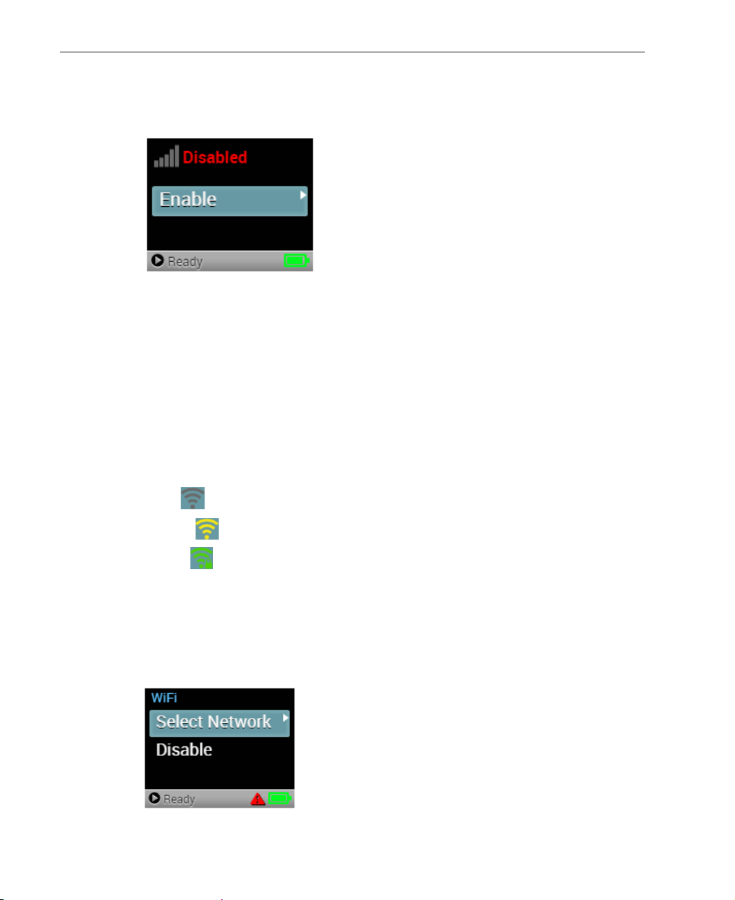
3 Navigate to a disabled interface using the Up and Down buttons on the
joystick and press the Right or Center (OK) buttons to display the
following screen:
Figure 32: Enable Interface
4 Press the Right or Center (OK) buttons on the joystick to enable the
selected interface.
Configuring WiFi
WiFi configuration can be performed directly on the LU200 unit itself or via
LiveU Cent ral.
The status of a WiFi network is indic ated, as follows:
• Gray : WiFi is disabled.
• Yellow : WiFi enabled, but is not connected.
• Green : WiFi is enabled and connected to the active network.
► To configure the LU200 using the LU200 u ser interface:
1 Navigate to the Interfaces option in the Main screen using the Up and
Down buttons on the joystick.
2 Select WiFi
Figure 33: Select Network
Select Network.
32
Page 33
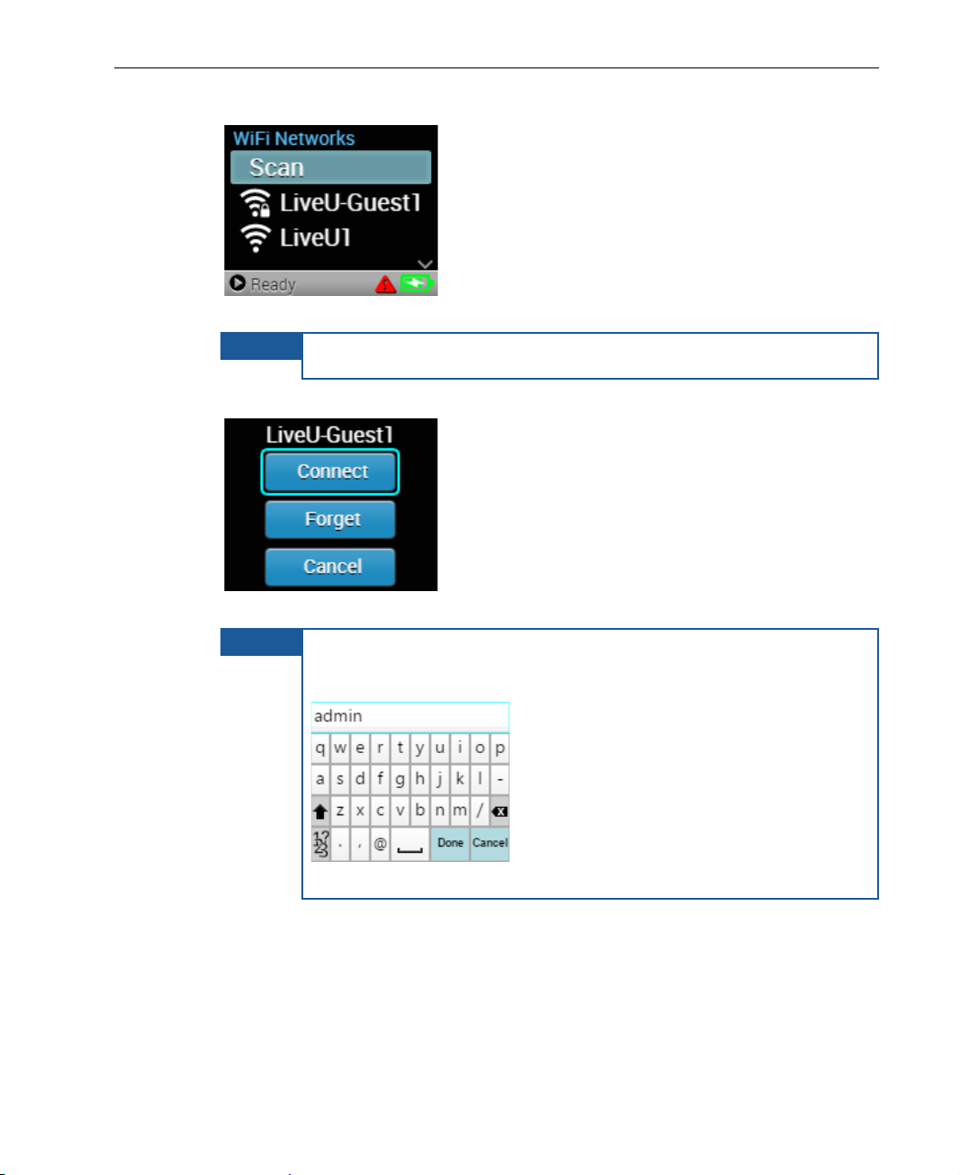
The unit scans and displays the available networks.
NOTE
NOTE
, as shown
Figure 34: Select Network
To rescan, press Scan.
3 Select a network and press Connect.
Getting Started
Figure 35: WiFi Network – Connect
For encrypted networks, select the ne twork, press Connect,
enter the network password using the virtual keyboard
below, and then press Done.
Figure 36: Virtual Keyboard
Disconnecting a WiFi Network
To disconnect a WiFi networ k , either disable WiFi or select a different network.
33
Page 34
LiveU LU200 User Guide
Configuring LAN Interfaces
Configuration of the LAN Static IP must be done in LiveU Cen tral. The unit’s
default value is DHCP. Configuration from the LU200 unit wi ll b e sup p or t ed in a
future release.
Step 7, Going Live
You are now ready to start transmitt ing the video to the channel that you
selected.
► To go live:
1 In the Main screen, use the arrows on the joystick to navigate to the
Profile option, and then press th e Center (OK) button on th e jo y stick.
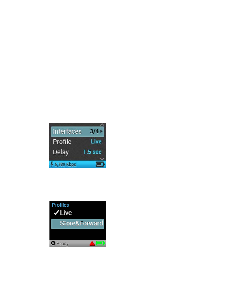
Figure 37: Main Screen
2 Navigate to the Live profile by using the Up and Down buttons on the
joystick and then press the Center (OK) button on the joystick to select it.
Pressing OK returns to the Main screen.
Figure 38: Profile Selection Screen
34
Page 35
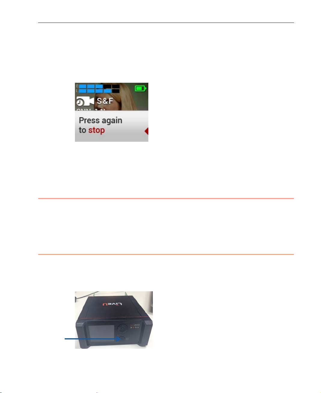
3 Short-press the Power button to start streaming.
Double-short-press the Power button when you want to stop streaming.
A popup message appears between these two short presses. If the second
short press is not performed with in tw o seconds of the first one, the popup
disappears and streaming conti n u es.
Figure 39: Stop Streaming Popup Mess ag e
When streaming begins, the Home screen displays to show the streaming
preview on the unit's screen, as described on page 21.
Step 8, H andling Aler t s
Getting Started
A No Camera Alert appe ar s on the home screen upper bar when the camera
is disconnected and it disappears when the c amera is connected back to the
LU-200 unit.
Step 9, Shutting Down
► To shut down the LU200:
Hold down the Power button for 5 seconds until the LU200 shuts down. This
action shuts down the unit’s softwar e and then turns off the unit.
Figure 40: Power Button
35
Page 36
LiveU LU200 User Guide
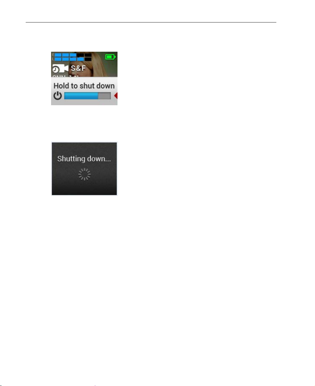
A popup message display s a pro gress bar for approximat e ly four to five
seconds while the unit is shutting down:
Figure 41: Shutdown − 1
Once the progress bar shows 100%, a popup message displ ay s , as shown
below. You should then stop pressing the power button.
Figure 42: Shutdown − 2
36
Page 37
3
LU200 User Interface
This chapter describes the main LU 200 screen and the options that it provides.
This chapter contains the following sections:
• LU200 Interface, page 38
• Interfaces, page 40
• Profile, page 40
• Delay, page 40
• Channels, page 40
• Configuration, page 41
• Files, page 44
• Unit Info, page 46
37
Page 38
LiveU LU200 User Guide
LU200 Interface
The LU200 user interface is an LCD screen. W h en the LU200 is powered on,
the Home screen displays, as described on page 19.
The Main screen provides access to the various configuratio n options for the
LU200.
► To go from the Home screen to the Main screen:
Press the Right button or the Center (OK) button on the joystick.
By default, when moving from the Home screen to the Main screen, the
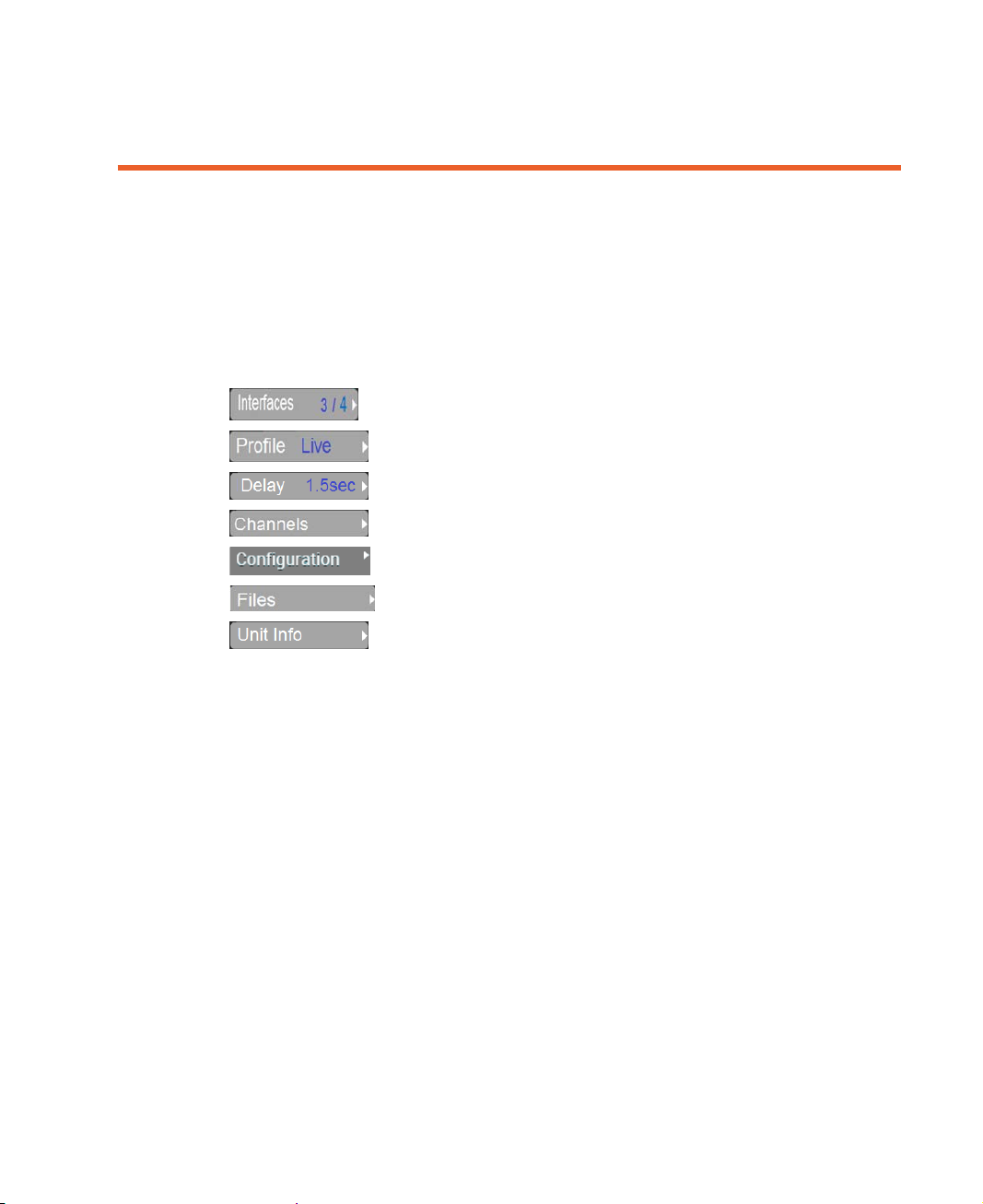
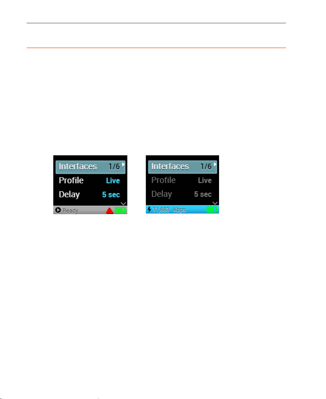
Interfaces o pt io n is in it i al ly selected, as show n below. The sel e cted option is
highlighted in gray on the screen.
When Not Streaming While Streaming
Figure 43: LU200 Main Screen
Because of the small size of the LU200 LCD screen, only three functions and
the Lower Status bar can be displayed at any given time on the screen, as
shown above.
38
Page 39
LU200 User Interface
NOTES
screen.
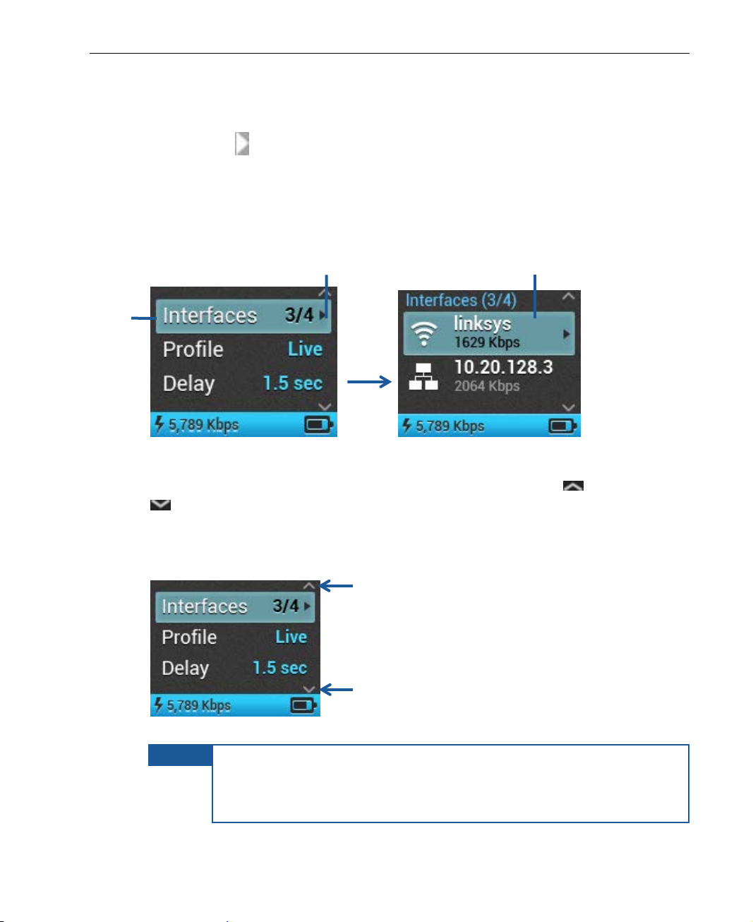
1 Navigate
2 Press the Right or OK button.
3 The Interfaces screen opens.
To select an option on the Main screen, use the Up and Down buttons on the
joystick to navigate to the applica ble option. Then, press the Right or Center
(OK) button on the joystick to access that option’s configuration screen . A
to here to
select the
Interfaces
option.
white arrow
next to an option on the Main screen indicates that the option
has a sub-menu and that you need to press the Right or Center (OK) button
to access the sub-menu screen.
The example below shows how to access the Interfaces screen from the Main
screen.
Figure 44: Accessing a Co nfiguration Screen
When additional op tions are available in the Main screen, up and/or down
arrows are shown on the screen, as shown below. These arrows indicate to
you to move up and down on the screen (using the Up and Down buttons o n
the joystick), in order to navigate to a different option on the Main screen that
is not seen on the screen.
Figure 45: LU200 Main Screen – Arrows Indica ti ng A dditional Options
Pressing the joystick’s Left button returns to the previous screen.
Pressing the joystick’s Right or Center (OK) buttons moves to the
next screen. From the Home screen, the next screen is the Main
39
Page 40
LiveU LU200 User Guide
The following sections describe the v arious options that are accessible from
the Main screen.
Interfaces
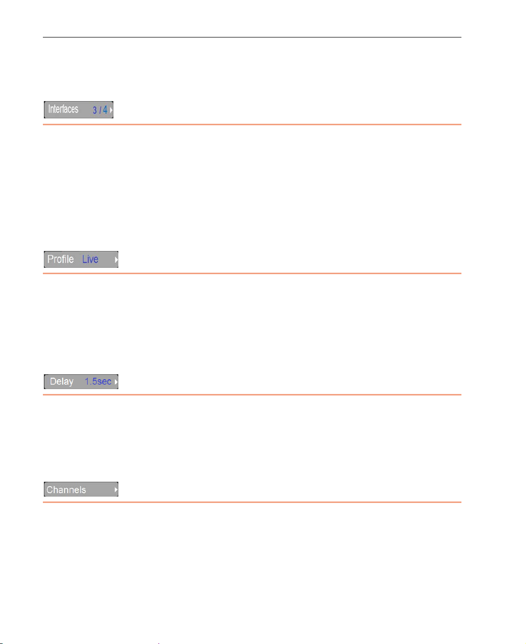
The Interfaces option in th e Main screen indicates the number of active
interfaces out of the total number of interfaces on the LU200. For example,
3 /4 means that there are three active interfaces and four total interfaces on
the unit, meaning that one of them is not active.
For more details about configur ing interfaces, see the Step 6, Handling
Interfaces section on page 27.
Profile
The Profile option in the Main screen shows the selected profile to use during
streaming.
For more details about setting the profile, see the Step 4, Selecting a Profile
section on page 24.
Delay
The Delay option in the Main screen shows the selected delay for streaming.
For more details about configuring the delay, see the Ste p 5, Setting the Delay
section on page 26.
Channels
The Channels option in the Main screen shows the channel to be used for
streaming, or for transferring files.
For more details about setting the channel, see the Step 3, Selecting a
Channel section on page 21.
40
Page 41
LU200 User Interface
Configuration
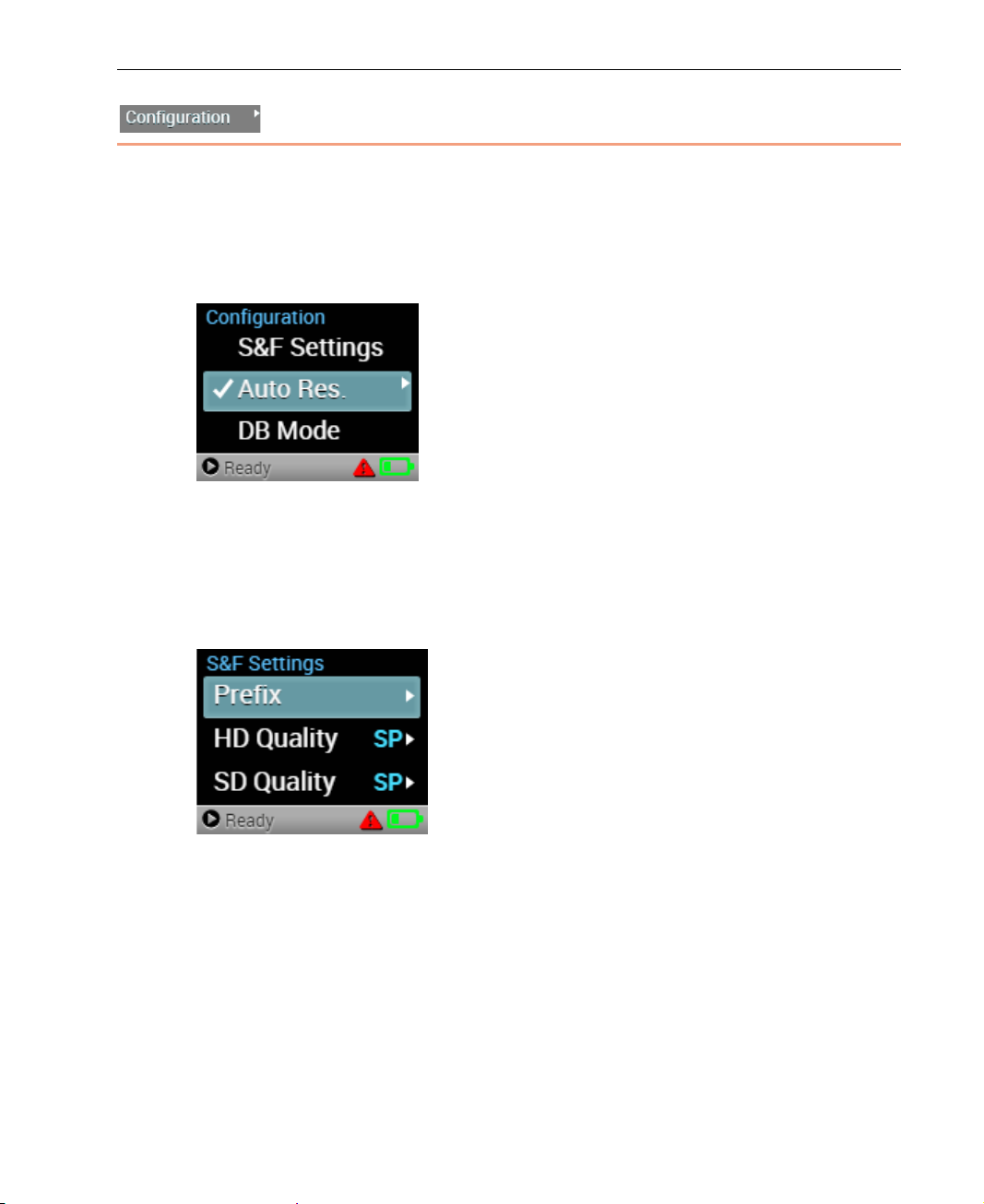
The Configuration option enables you to perform the following operations:
• Conf i gu re S&F Settings, page 41
• Enabling Auto Resolution, page 44
• Operate as a DataBridge, page 44
Figure 46: Configuration Options
Configuring S&F Settings
LU200 enables you to configure Store & Forward (S&F) settings for Store &
Forward sessions.
Figure 47: S&F Settings
41
Page 42
LiveU LU200 User Guide
► To configure the S&F prefix:
1 Navigate to the S&F Settings option in the Configuration screen using the
Up and Down buttons on the joystick.
2 Navigate to the Prefix option in the S&F Settings scree n and press the
Right or Center (OK) buttons on the joystick. The following screen
displays:
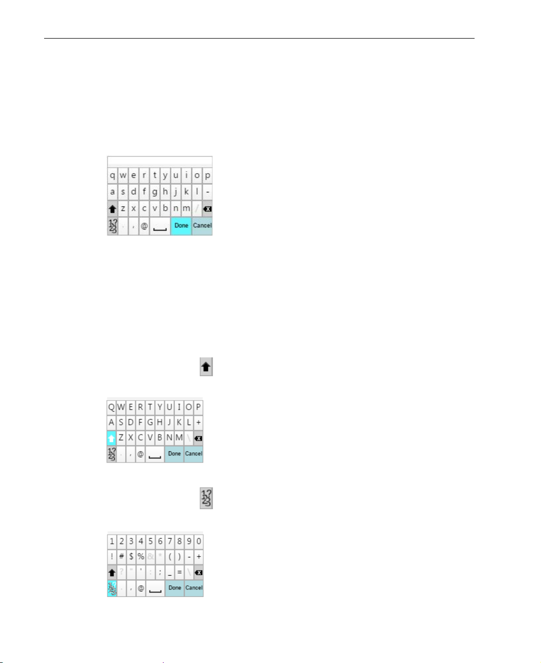
Figure 48: Prefix Screen
3 Enter the prefix to be appended to the filename for the files streamed from
the LU200, and then press Done. The prefix enables you to differentiate
between files that were stored and forwarded.
To use the keyboard, navigate through the keyboard characters using the
Up, Down and Right buttons on the joystick. To select a character, pr e ss
the Center (OK) button.
When pressing the button, the letters on the keyboard chan ge f rom
lower case to upper case, as shown below:
Figure 49: Prefix Screen – Capital Letters
When pressing the button, the letters on the keyboard chan ge to
numbers and special characters, as shown below:
Figure 50: Prefix Screen – Numbers and Special Characters
42
Page 43
LU200 User Interface
► To configure the S&F quality:
1 Navigate to the S&F Settings option in the Configuration screen using the
Up and Down buttons on the joystick.
2 Navigate to the HD Quality option in the S&F Settings screen and press
the Right or Center (OK) buttons on the joystick. The following screen
displays:
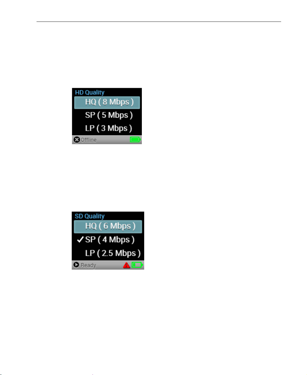
Figure 51: HD Quality Screen
3 Select the HD video quality for the stored file. You can select one of the
following options: HQ (High Quality), SP (Standard Play) or LP (Long
Play). Press the Center (OK) button on the joystick to set the value.
4 Navigate to the SD Quality option in the S&F Settings screen and press
the Right or Center (OK) buttons on the joystick. The following screen
displays:
Figure 52: SD Quality Screen
5 Select the SD video quality for the stored file. You can select one of the
following options: HQ (High Quality), SP (Standard Play) or LP (Long
Play). Press the Center (OK) button on the joystick to set the value.
43
Page 44
LiveU LU200 User Guide
Enabling Auto Resol ution
When Auto Resolution is enabled, the LU200 automatically adjusts the
resolution at which it transmit s according to the bit rate that is available in
order to provide the best available video quality on the server side. To enable
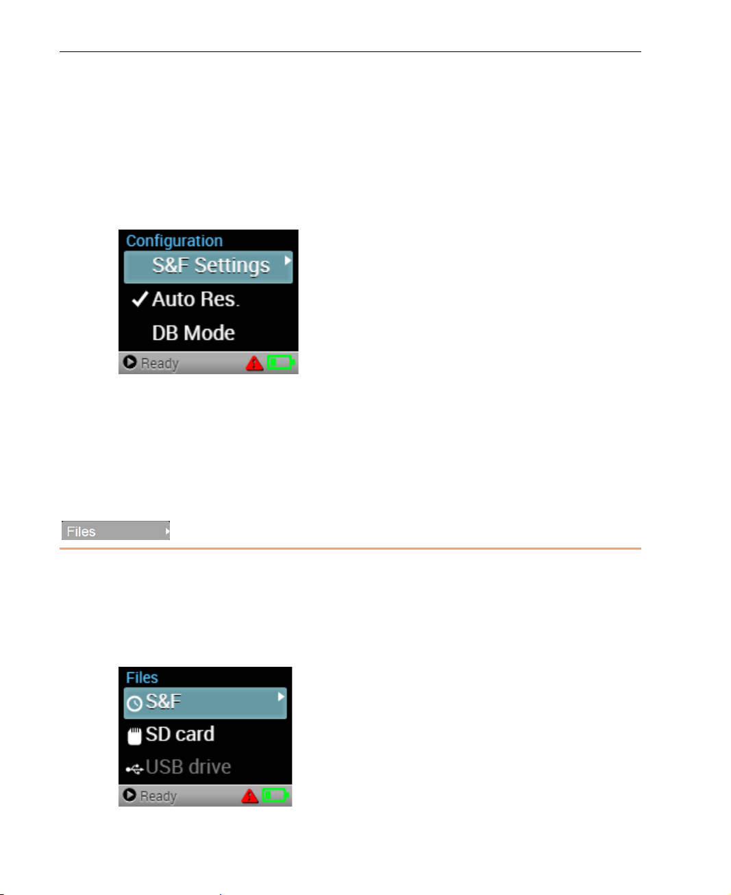
this feature, navigate to the Auto Res. option in the Configuration screen and
then press the Right or Center (OK) buttons on the joystick to enable or
disable, as required. This feature is enabled by default.
Figure 39: Auto Res. Setting
Operating as a DataBridge
The LU200 unit can operate as a DataBridge when working in DataBridge (DB)
mode, as described in Ch apter 5, DataBridge Operation on page 51.
Files
The Files option enables you to perform the following operations:
• Display S&F Files, page 45
• Display SD Card Files, page 45
• Display USB Drive Files, page 46
Figure 53: Files Options
44
Page 45
LU200 User Interface
Displaying S&F Files
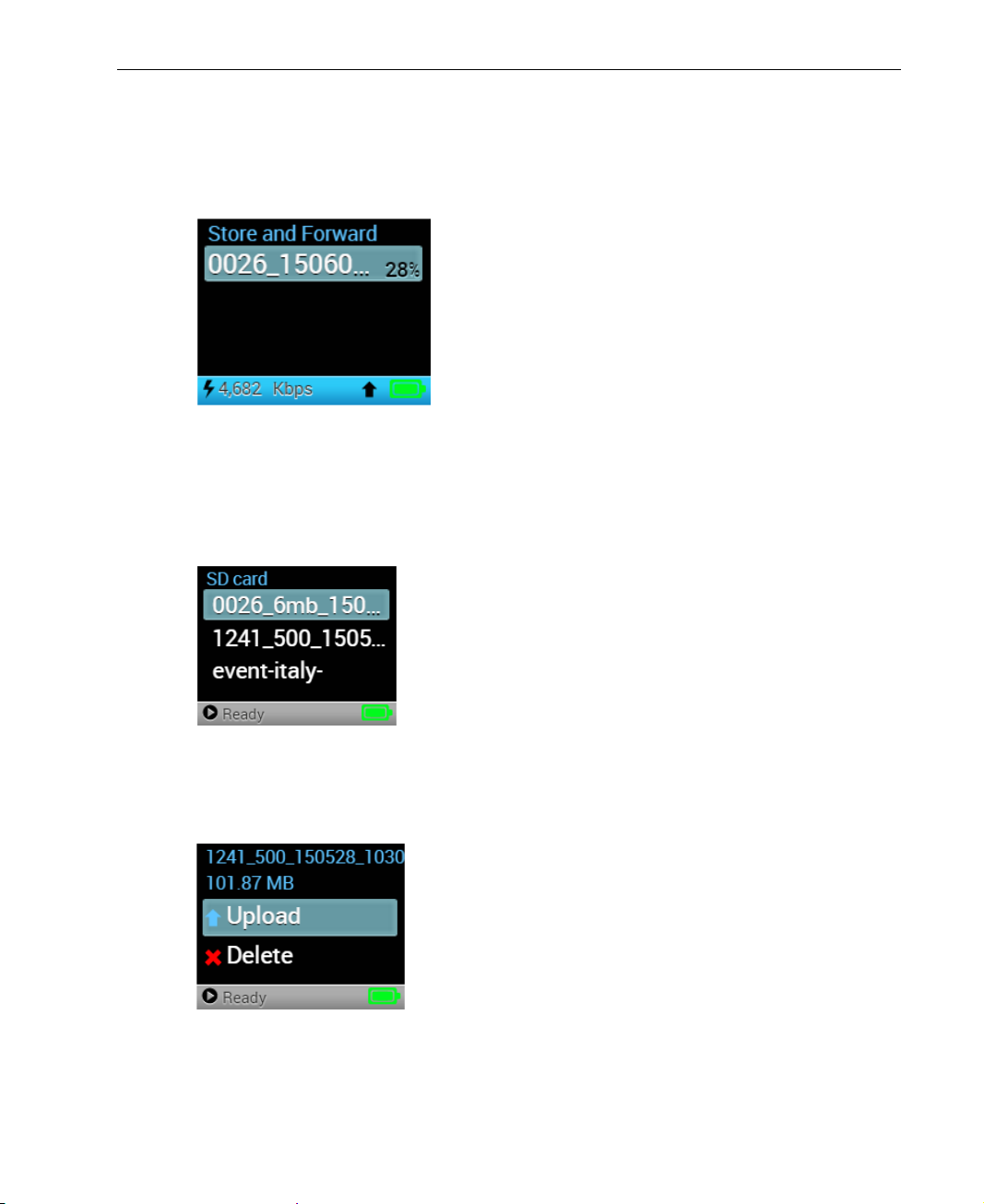
The S&F option displays all the files that are currently being stored and
forwarded.
Figure 54: Store and Forward
Displaying SD Card Files
The SD Card option displays a list of th e f iles on the SD card.
Figure 55: SD Card Option
You can upload or de lete files in the li st using t h e respective option, as shown
below:
Figure 56: SD Card – Upload and Delete Options
You can upload or delete files in the list using the respective Upload or Delete
option.
45
Page 46
LiveU LU200 User Guide
NOTE
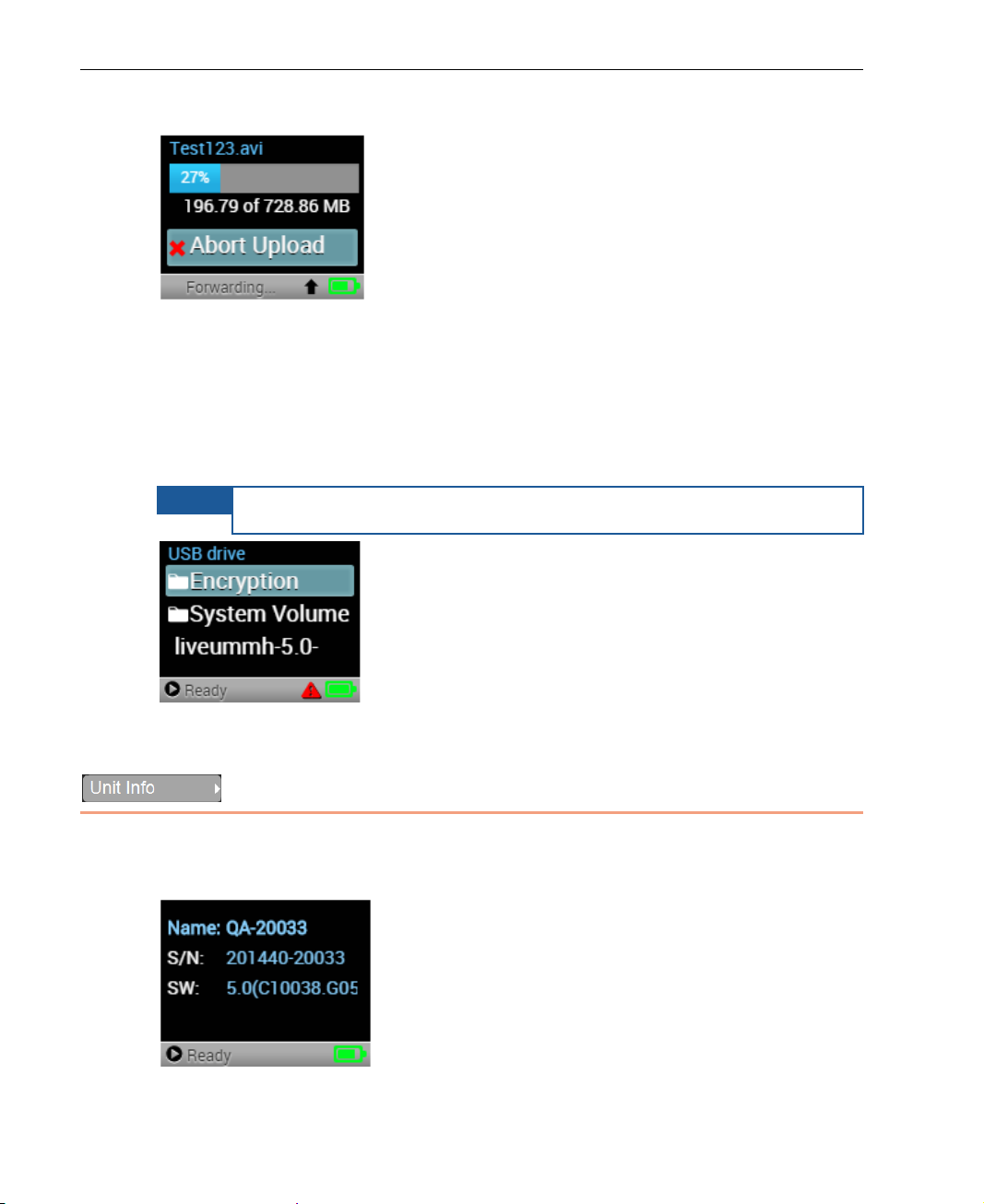
After an upload has been initiated, a progress bar displays, as shown below:
Figure 57: Uploading – Progress Bar
You can abort a file upload operation using the Abort Upload option.
Displaying USB Drive Files
The USB Drive option displays a list of the files on the USB drive.
The USB drive must be connected to USB port 1 or 2.
Figure 58: USB Drive – Files List
Unit Info
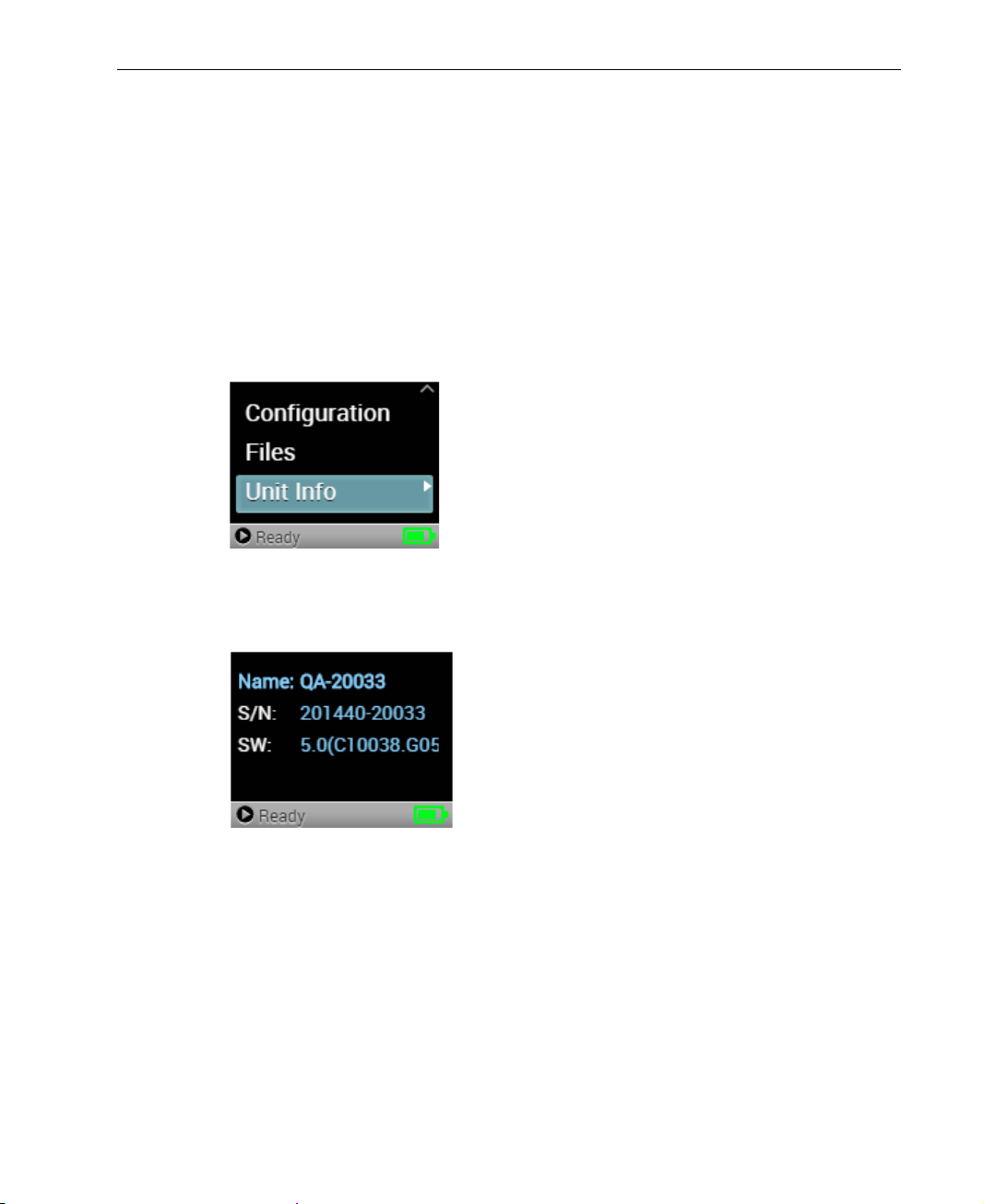
The Unit Info option displays the LU200 unit’s name, serial number and
software version. If required, you may contact LiveU support for more details.
Figure 59: Unit Info Screen
46
Page 47
LU200 User Interface
If any of the information on this screen i s longer than the screen permits, two
dots (..) are displayed at the end of the r elevant line. After a few seconds, the
currently selected information line starts to scroll so that you can see the rest
of the information.
When contacting a support r epresentative, make sure to have the last fo ur
digits of the LU200 unit’s s erial number availa ble.
► To view unit information:
1 In the Main screen, use the arrows on the joystick to navigate to the Unit
Info option.
Figure 60: Main Screen
2 Press the Center (OK) button on the joystick to display the Unit Info
screen.
Figure 61: Unit Info Screen
47
Page 48

LiveU LU200 User Guide
Blank page for double-sided printing
48
Page 49

4
Interrupted Feedback
(IFB)
This chapter describes the LU200’s IFB Interrupted Feedback (IFB) fe atur e and
how to set it up.
IFB Overview
The IFB feature provides a unidirectional audio channel from the LU2000 to
LU200 unit operators in the field. This enables the personnel in the master
control room (MCR) to broadcast verbal instructions or information about
events to LU200 operators.
During broadcasting, LU200 operators can listen to an audio-only chann el
received from the IFB server using an earphone/headph on e. IFB uses a
unidirectional audio channel from the LU2000 to the LU200 unit, w hi ch onl y
allows the LU200 operator to listen, but not respond.
For more details about the IFB feature on th e LU2000, see Appendix A,
Interrupted Feedback (IFB) in the LiveU LU2000 Server User Guide.
49
Page 50
LiveU LU200 User Guide
IFB Setup
Perform the step below before beginning stre amin g, in order to ensure proper
IFB operation.
► To set up IFB:
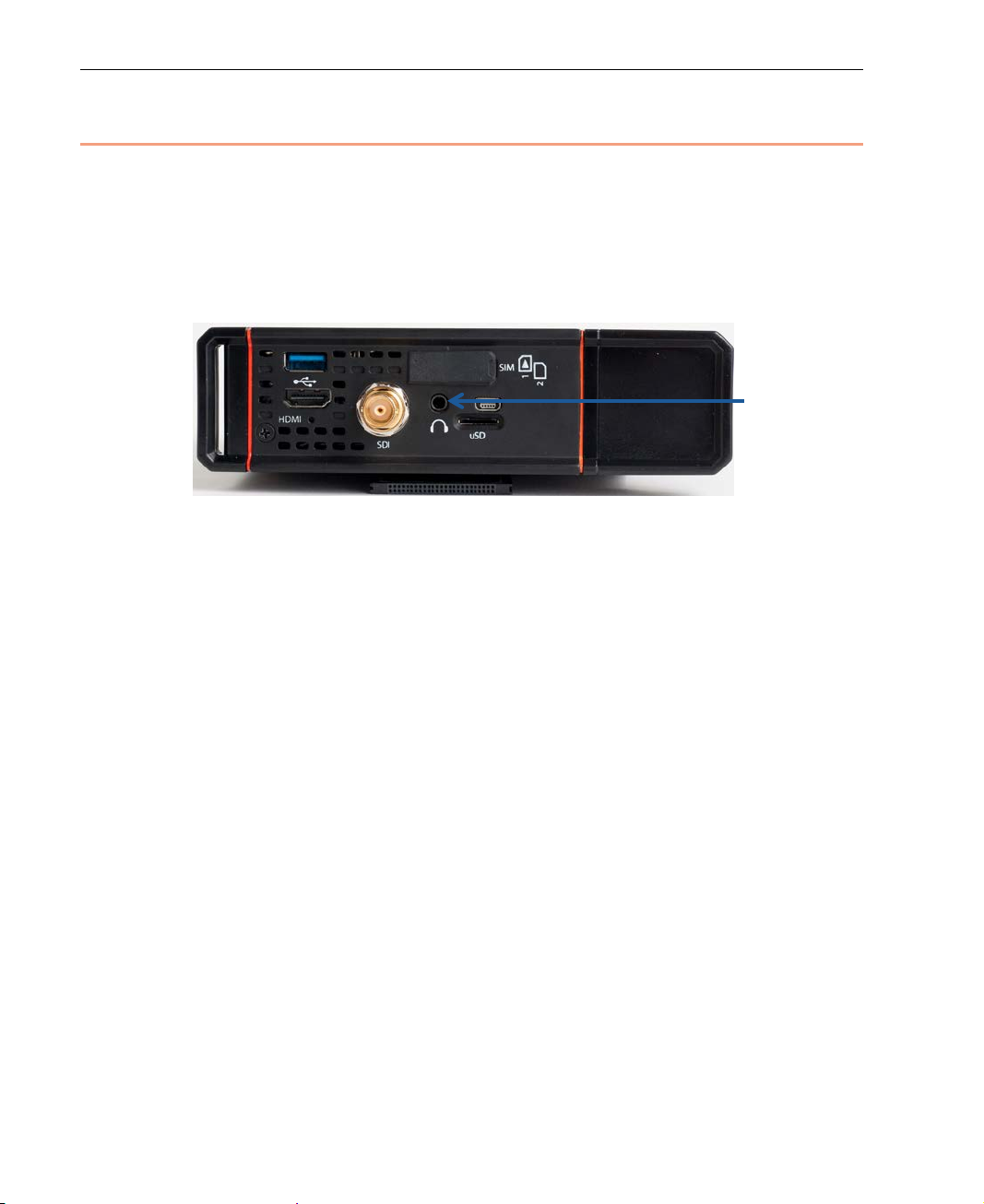
• Plug in the earphones/headphones into the microphone connector on the
LU200. No other setup or configuration is required on the LU200.
Figure 62: Earphones/Headphones Connec t or
If the earphones/headphones are connected after streaming starts, the
LU200 operator cannot hear anything on the IFB channel. Be sure to
connect them before starting to stream.
During streaming, IFB has an 800ms delay.
50
Page 51
5
DataBridge
Laptop
Cellular Core Networks
UMTS
EVDO
EDGE
Satellite
Network
Core Packet
Switched
Network
DataBridge Gateway
DataBridge Operation
This chapter describes LiveU ’s D ataBridge solution and how to operate the
LU200 unit as a DataBridge.
This chapter contains the following sections:
• LiveU DataBridge Solution, page 51
• DataBridge Mode, page 53
LiveU DataBridge Solution
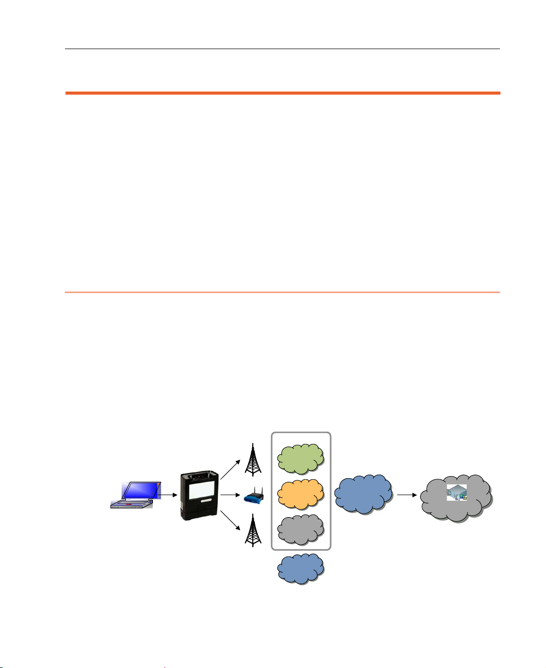
LiveU’s DataBridge solution enables point-to-multipoint transmission and
reception of any kind of high-quality data from diverse lo cations, while
adapting to dynamic net work conditions. The D ataBridge feature can be used
for a variety of data connectivity solutions, such as for connecting a laptop in
the field to a control station.
DataBridge Operation
The DataBridge solution is a client/server solution where an LU, such as the
Xtender, LU200, LU400, LU 40 o r LU500, that is configured t o operate as a
DataBridge unit, is the client and the D ataBridge Gateway is the server.
Figure 63: DataBridge Solution Architecture
51
Page 52

LiveU LU200 User Guide
After the DataBridge unit powers u p, it dials (connects) its modems to v arious
networks and combines their bandwidth into a single consolidated broa dband
uplink and downlink connection:
• Transmitting Data: The DataBridge unit rec eives data fro m the user data
equipment through its user por t and tr ansmits it over the aggregate d
bandwidth.
• Receiving Data: The DataBridge device receives incoming dat a thr ou gh
its aggregated bandwidth, and outputs it through its user port to the user
data equipment.
DataBridge Gateway
The DataBridge Gateway server is locat ed in the cloud, and receives various
streams of data from the DataBridge unit through its network port, which is
connected to standard Internet. The D ataBridge Gateway server runs mu ltiple
remote connection instances. E ach r em o te connection instance recom bines the
streams received from a specific DataBridge unit into a discrete high-quality
data stream.
DataBridge Unit
Each DataBridge unit streams to a specific remote connection instance on the
DataBridge Gateway. The DataBr idge Gateway can service up to 100
DataBridge units simultaneously.
The DataBridge unit:
• Employs propriet a ry algorithms to s imultaneously break down and transmit
data over multiple modems a nd to bond the data received ov er its multiple
modems.
• Performs Layer 2 bridging by learning Layer 2 sourc e addr e sses and
forwarding according to Layer 2 dest ination MAC addresses.
An LU200 working as a DataBr idge unit operates in DataBr id ge m ode . For
more details, see the DataBridg e Mode section on page 53.
52
Page 53
DataBridge Mode
The LU200 unit must be switched from Video mode to DataBridge mode in
order to operate as a DataBr idge. The LU200 conti nu es to o per ate in
DataBridge mode until it is sw itched back to Video mode. When switching
between these two modes, the LU200 unit is rebooted.
► To change to DB Mode:
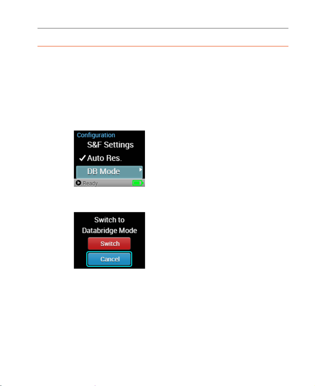
1 In the Main screen, use the Up and Down buttons on the joy stick to
navigate to Configuration menu and then the DB Mode option. Then
click the Center (OK) button on the joystick to select it.
Figure 64: Main Screen
DataBridge Operation
The following screen displays:
Figure 65: Switching to DB Mode
2 Navigate to the Switch option using the Up and Down buttons on the
joystick and then press the Center (OK) button on the joystick to select it.
After selecting this option, the LU200 reboots and operates in DataBrid ge
(DB) mode, as described below.
53
Page 54
LiveU LU200 User Guide
NOTE
Gateway, contact LiveU PSG for assistance.
Operating in DataBridge Mode
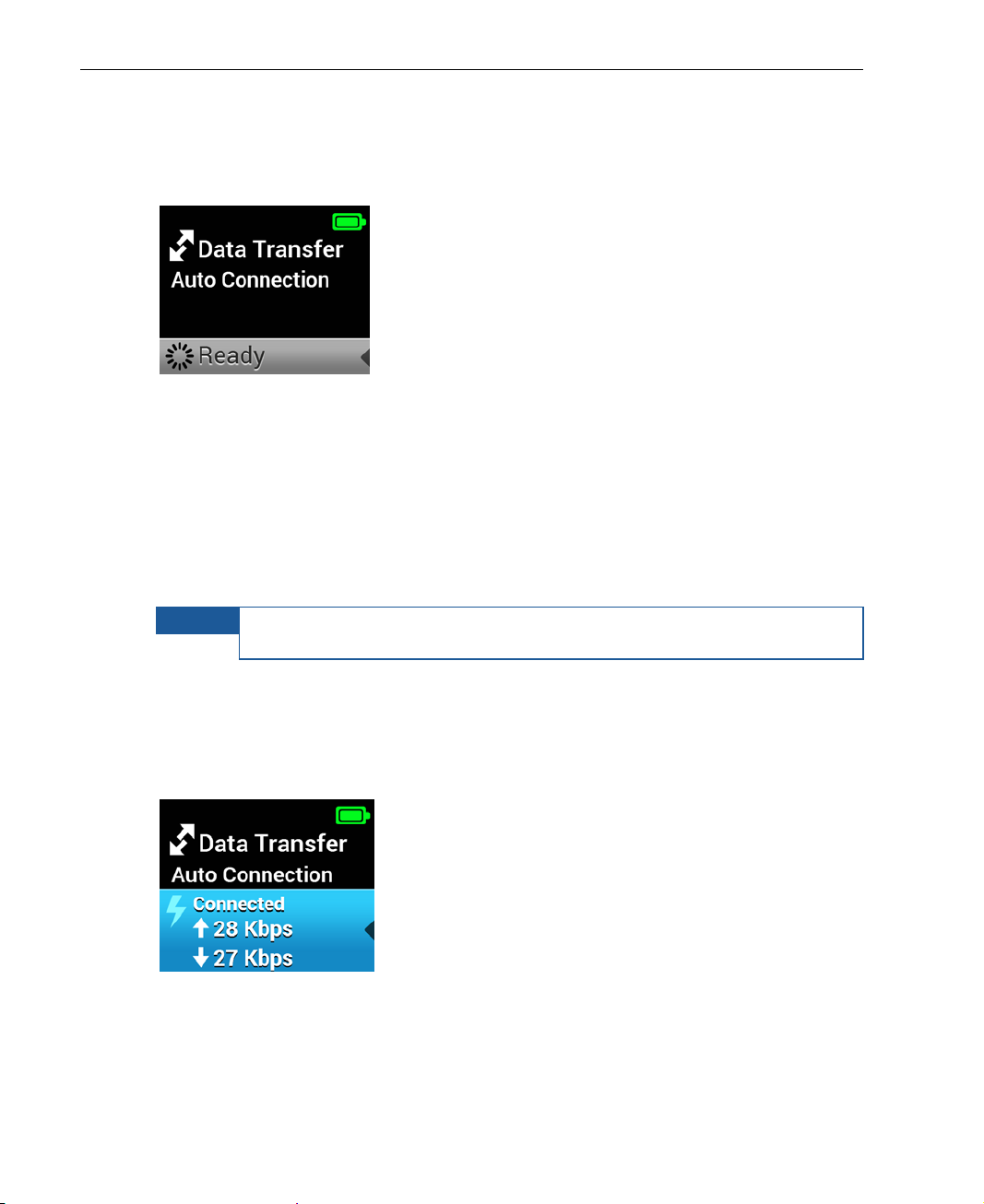
After the LU200 reboots and switches to DB mod e, the fo l lowing screen
displays:
Figure 66: After Switching to DB Mode
In order for the LU200 to operate as a Data Bridge, the unit must be connected
to a DataBridge Gateway ins tance. Conn e ction to a DataBridge Gateway
occurs automatically, once a Dat aBridge Gateway instance is assign ed to the
LU200 unit by LiveU. You must contact the LiveU Professional Services Gr o up
(PSG) and request that a DataBridge Gateway instance be assigned to the
LU200 unit for this purpose. After the PSG assigns a DataBridge Gatew ay ( via
LiveU Central), the unit automatically connects to the gateway.
If the LU200 does not automatically c o nn ect to the DataBridge
The LU200 unit then connects to the DataBridge Gateway to be used for the
connection.
After the LU200 unit is connected in DB mode, details about the connection
status are displayed, as shown below:
Figure 67: After Connecting to the DataBridge Gateway
The LU200 unit continues to oper ate in DB mode until it is switched back to
Video mode.
54
Page 55
DataBridge Operation
► To change back to Video Mode from DB Mode:
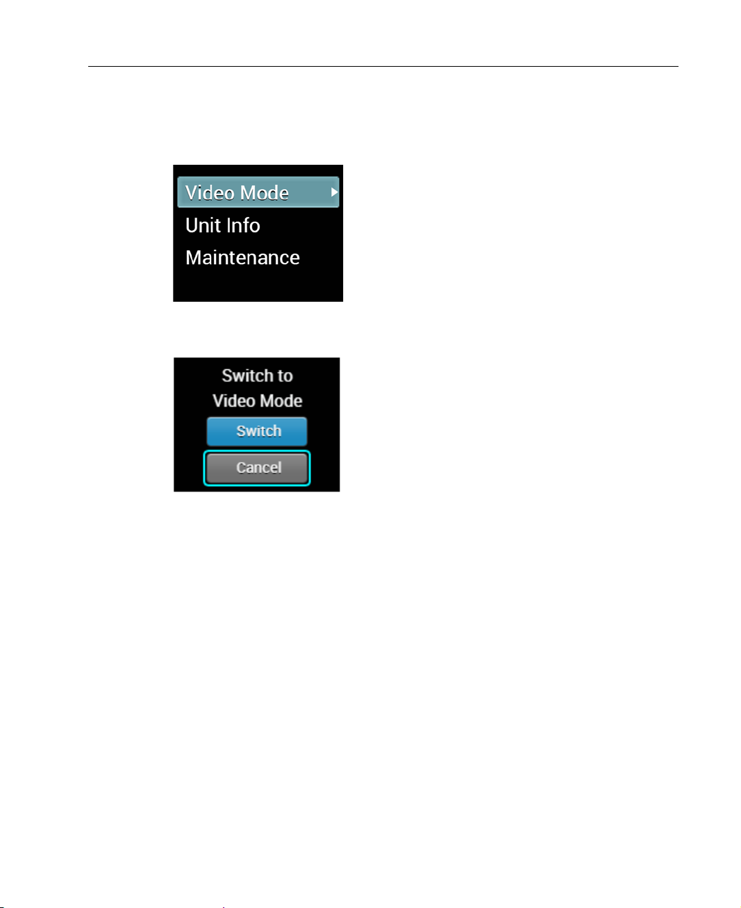
1 In the Main screen, use the Up and Down buttons on th e jo y stick to
navigate to the Video Mode o ption and t hen press the Center (OK)
button on the joystick to select it.
Figure 68: Changing to Video Mode from DB Mo de
The following screen displays:
Figure 69: Back to Video Mode
2 Navigate to the Switch option using the Up and Down buttons on the
joystick and then press the Center (OK) button on the joystick to select it.
The LU200 reboots and oper ates in Video mode (the def ault).
55
Page 56
LiveU LU200 User Guide
Displaying Unit Information
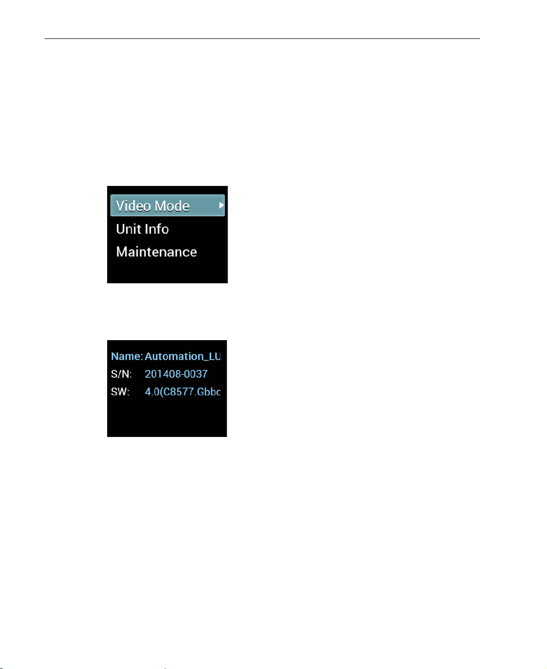
Use the Unit Info option to display additional information about the LU200
unit.
► To display LU200 unit information:
1 In the Main screen, use the Up and Down buttons on th e jo y stick to
navigate to the Unit Info option and then press the Center (OK) button
on the joystick to select it.
Figure 70: Changing to Video Mode from DB Mo de
The following screen displays, showing the name, serial number and
software version for the LU200 unit.
Figure 71: Unit Info
56
Page 57

6
FAQs
This chapter answers various frequ en tly asked questions about the LU200.
1 Does the LU200 come with SIM cards
installed?
This depends on whether the LU200 was purchased (is provided without SIM
cards) or leased (is provided with SIM cards).
2 Where are SIM cards placed?
For internal Cellular modems there are 2 slots to insert the SIM cards.
3 How do I know which SIM cards are
supported in my country?
Browse to the following link to see a list of the operators in your country. All
operators listed under GSM should work with the modems provided in th e
LU200.
http://en.wikipedia.org/wiki/Mobile_Network_Code
Contact a LiveU support representative if you are need additional assistance.
57
Page 58
LiveU LU200 User Guide
LU Unit
Ready
4 What is the next step after inserting the
SIM cards into the LU200 unit?
The following options are available for configuring the Access Point Number
(APN):
• By default, the LU200 automatically con figures the correct APN.
• If the system fails to automatically configure the APN, then you may r ef er
to the LiveU Central User Guide for a description of how to configure the
APN.
5 How do I know whether or not the
LU200 unit is connected to the Internet?
You have the following options:
• Check that the unit is in Ready state and is not offline.
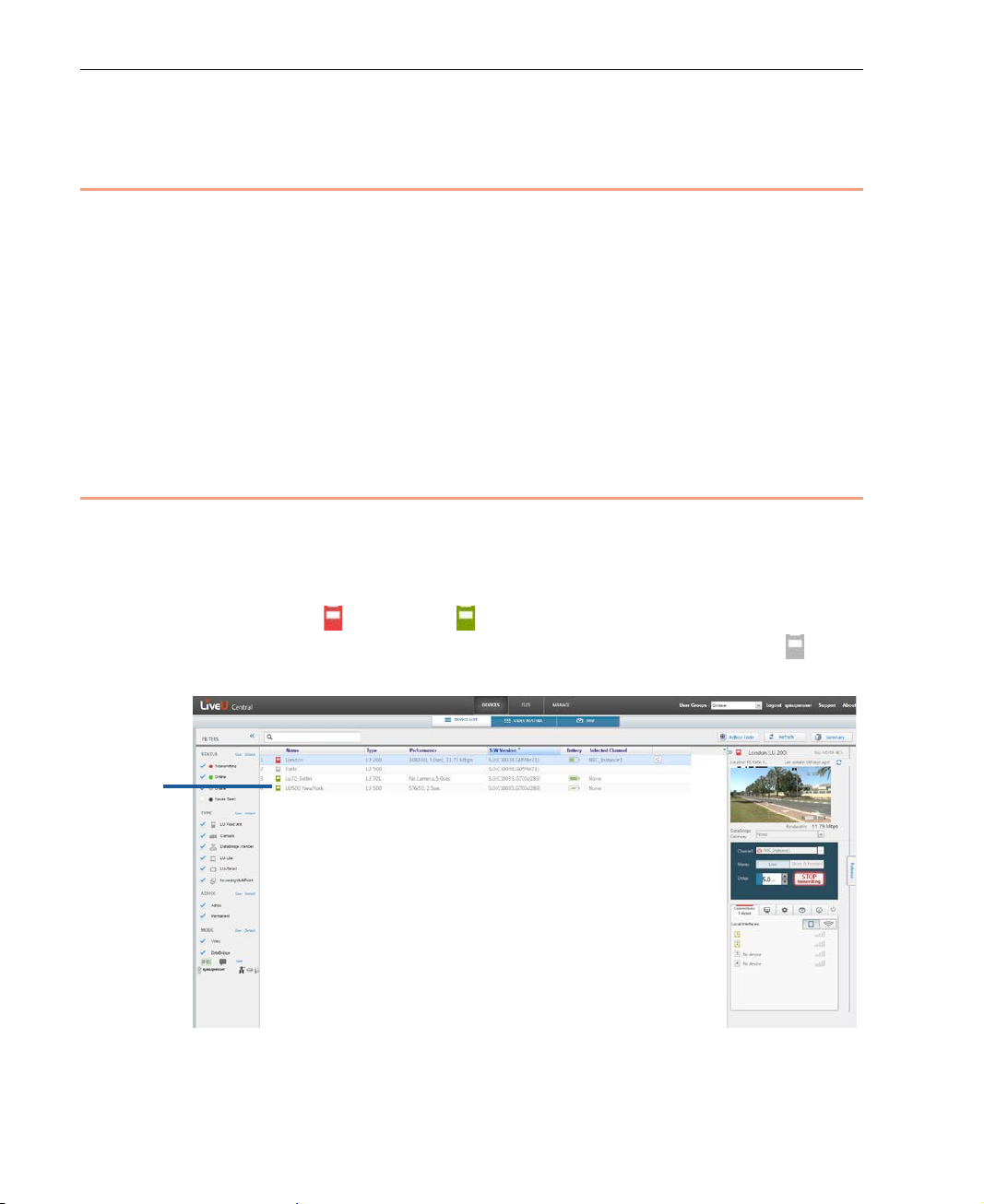
• LiveU Central: Use the LiveU Central web interface to check if the LU200
unit has Live ( ) or Ready ( ) status, as shown below. Both of these
statuses indicate that the LU200 i s co n n e cted. The Offline status ( )
indicates that the LU200 is not connected.
Figure 72: LiveU Central
58
Page 59

FAQs
You may refer to the LiveU Central User Guide for more information. It
describes how to remotely manage and control LU200s and L U2000s on an
LU2000 server through a standard Internet browser.
6 The LU200 unit does not connect to the
Internet. What is the p roblem?
• There is no cellular reception.
• There are no SIM cards inserted in the LU200 unit.
• SIM cards were inserted only after the unit was turned on.
• The SIM cards are not activated or do not support the data plan.
• Modems are disabled.
• The APN is not configured correctly on the modems.
7 I want HDMI ou tpu t on th e LU 200 0.
What should I do?
Currently, the LU2000 does not support HDMI output. To provide HDMI output,
an SDI-to-HDMI convertor can be used.
8 I have an LU-1000 server. How d o I
connect my LU200 to it?
This option is not a vailabl e.
9 What is the purpose of the micro SD
slot?
The micro SD slot is for the Store&Forward option (describe d o n page 23).
59
Page 60

LiveU LU200 User Guide
10 Which modems can be used in the
LU200?
Verify which modems can be used with your LiveU suppor t r epr esentative.
11 Does th e LU 200 unit support 4G (LTE)?
Yes, the LU200 is supported upon 4G network availability.
12 In which c ountries does the LU200
work?
All over the world!
13 How do I get support for the LU200?
You may refer to the Support and Contacting Information section on page 8 for
more information.
14 Can I stre am directly to the web? How?
Yes, this package can be purchased f rom LiveU sales. You may refer to the
Support and Contacting Informati o n section on page 8 for more information.
15 How many hours does the battery last?
The LU200 has an internal battery that when fully charged enables up to two
hours of standalone operation.
60
Page 61
16 Why can’t I hear using the
1080p50 and 1080p60 are only supported on the i n pu t , but not on
the server side.
earphones/headphones?
For the IFB feature to work properly, earphones/headphones must be
connected before the streaming starts. If they are not connected before
streaming starts, the LU user cannot hear anyth in g on the audio ch annel. For
more details, see the IFB Setup section on page 50.
In addition, the IFB feature must be properly configured on the LU2000 serv er.
For more details, see Appendix A, Interrupted Feedback (IFB) in the LiveU
LU2000 Server User Guide.
17 Can I stream to multiple channels
(LU2000s) a t the sam e ti me ?
Currently, this fe a ture is n ot available. It will be available in future re leases.
FAQs
19 Which camera resolutions are
supported?
The LU200 supports the following camera input resolutions:
• 1080p50/60/25/30/24
NOTE
• 1080i50/60
• 1080i59.94
• 720p50/60/25/30/24
• SD NTSC 720x480
• SD PAL 720x576
61
Page 62

LiveU LU200 User Guide
Blank page for double-sided printing
62
Page 63
A
Safety and Maintenance
CAUTION
mechanical h azards.
CAUTION
This appendix describes how to maintain the LU200 and how to handle
potential hazards .
This appendix contains the following sections:
• Safety Information, page 63
• Potential Hazards, page 65
Safety Information
Do not disassemble this product. Do not remove its cover or its
back. There are no user-serviceable parts inside. Refer servicing
to qualified service personnel only. The use of controls,
adjustments or procedures other tha n tho se specified in the
guide may result in exposure to shock and/or electrical or
• Avoid shorting the battery.
• Do not immerse it in water.
• Do not disass em ble or deform the battery.
• Do not expose the battery to fire and do not dispose o f the
• Only use the original battery model.
• Battery storage temperature limit s ar e -20°C – 60°C, < 80% RH. Store the
battery in an environment with low humidity that is free from cor rosive
gas.
• Only use the originally approved power supply a dapter.
battery in fire.
• Avoid excessive physical shock or vibration of the battery.
• Keep the battery out of the reach of children.
• Never use a batter y that appears to have suffered abuse.
63
Page 64

LiveU LU200 User Guide
• Only use the supplied accessories. A ccessories (including cables) must not
be replaced.
• Do not use the product if there is any physical damage to the enclosure.
• Keep all air inlets and outlets free of any objects that may interf er e with
the air flow for at least 10 cm.
• It is normal for the product to become slightly hot during use. However, if
the enclosure's temperature becomes unbearable to touch, turn the
product off and contact support.
• Avoid leaving the product unprotected in direct sunlight for more than five
minutes.
• Do not let the product come into contact with corrosive materials.
• Do not let the product come into contact with explosive or corrosive gas.
• Do not let the product come into contact with fire.
• To prevent fire or shock hazard, do not expose the product to rain, liquid
or moisture. The product can be used in light rain while it is protected by
the attached rain hood. Th e product is definitely not designed to be used
under water.
• Only use the original LiveU backp ack. Do not place the product in a non-
LiveU bag.
• If the LCD breaks, do not touch the g la ss.
64
Page 65

Potential Hazards
The LU Live Video Uplink unit conta ins cellular devices that should be op e r ated
according to the same rules and limitations as expected from norma l cellular
devices. Do not operate the LU Client Enclosure in an environment that may
be susceptible to radio interfe rence resulting in danger, specifically:
• Areas where prohibited by the law.
Follow any special rules and regulations and obey all signs and notices.
Always ensure that the enclosure is tur ned off (the power switch is not lit)
when instructed to do so, or whenever it may cause interference or
danger.
• Where explosive atmospheres may be present.
Do not operate the LU enclosure in any area where a potent i al ly explosive
atmosphere may exist. Sparks in such areas could cause an explosion or
fire resulting in b odily injury or even death. B e aware and comply with all
signs and instructions.
• It is not advisable to operate the LU Live Video Uplink whi le at a ref ueling
point or service station.
Safety and Maintenance
Users are reminded to observe restrictions on the use of radio equipment
in fuel dep ots (fuel storage and distribution a reas), chemical p lants or
where blasting operat ions are in progress.
• Areas with a potentially explosive a tmosphere are often, but not always,
clearly marked.
Potentia l loc a tions can include gas stations, below deck on boats, chemical
transfer or storage facilities, vehicles using liquefied petroleum gas (such
as propane or butane), areas where the air contains chemicals or particles,
such as grain, dust or metal powders, and any other area where it would
normally be advisable to turn off a vehicle’s en gine.
• Near medical and life support equipment.
Do not operate the LU Enclosure in any area where medical equipment, life
support equipment or near any equipment that may be susceptible to an y
form of radio interference. In such areas, the host communications device
must be turned off. The LU Enclosure may transmit signals that could
interfere with this equipment.
65
Page 66

LiveU LU200 User Guide
• On an aircraft, either on the ground or airborne.
In addition to FAA requ irements, many airline regulations state that
wireless operations must be suspended before boarding an airplane. Plea se
ensure that the LU Enclosure is turned off prior to boarding aircraft in order
to comply with these regulations. The enclosure can transmit signals that
could interfere with various on boar d systems and controls.
• While operating a vehicle.
The driver or operator of any vehicle should not operate a wireless data
device while in con trol of a v ehicle. Doing so de tracts the driver or
operator's control and operation of that vehicle. I n so m e co un tries,
operating such communications devices while in control of a vehicle is an
offense.
For more information, visit www.liveu.tv.
66
Page 67

B
Limitation of Liability and Warranty
This appendix describes the limitations on liability and warranty.
Limitation of Liability and Warranty
This LiveU product is provided “as is” without warranty of any kind. The
company disclaims all other warranties, either express or implied, including
but not limited to implied warranties o f merchantability and fitness fo r a
particular purpose and non-infringement.
Under no circumstances shall the co m pany be liable for any damages
whatsoever (including, without limitation, consequential, special, or incidental
damages, or damages for loss of business profits, business interruptions, loss
of business information or other pecuniary loss) arising out of the use of or
inability to use the LiveU product, even if the company has been advised of the
possibility of such damages.
NOTICE TO CUSTOMERS
Notice Required for the License Granted under Articles 2.1 and 2.6. As
a condition of the licenses granted pursuant to Articles 2.1 and 2.6 h ereof,
Licensee agrees to provide to any party that receives from Licensee an AVC
Royalty Product the following notice: THIS PRODUCT IS LICENSED UNDER THE
AVC PATENT PORTFOLIO LICENSE FOR THE PERSONAL USE OF A CONSUMER
OR OTHER USES IN WHICH IT DOES NOT RECEIVE REMUNERATION TO (i)
ENCODE VIDEO IN COMPLIANCE WITH THE AVC STANDARD (“AVC VIDEO”)
AND/OR (ii) DECODE AVC VIDEO THAT WAS ENCODED BY A CONSUMER
ENGAGED IN A PERSONAL ACTIVITY AND/OR WAS OBTAINED FROM A VIDEO
PROVIDER LICENSED TO PROVIDE AVC VIDEO. NO LICENSE IS GRANTED OR
SHALL BE IMPLIED FOR ANY OTHER USE. ADDITIONAL INFORMATION MAY BE
OBTAINED FROM MPEG LA, L.L.C. SEE HTTP://WWW.MPEGLA.COM
67
Page 68

LiveU LU200 User Guide
Notice Required for the License Grant ed und er Arti cle 2.6 and for Sales
to Codec Licensee customer(s). As a condition o f the licen se granted under
Article 2.6 and the license granted to a Codec Licensee to make sales to Codec
Licensee Customer(s), Licensee a grees to provide any party that rece ives an
AVC Product from Licensee exercising such license rights the following notice:
THIS PRODUCT IS LICENSED UNDER THE AVC PATENT PORTFOLIO LICENSE.
SUCH LICENSE EXTENDS TO THIS PRODUCT ONLY AND ONLY TO THE EXT E NT
OF OTHER NOTICES WHICH MAY BE INCLUDED HEREIN. THE LICENSE DOES
NOT EXTEND TO ANY OTHER PRODUCT REGARDLESS OF WHETHER SUCH
PRODUCT IS INCLUDED WITH THIS LICENSED PRODUCT IN A SINGLE
ARTICLE. ADDITIONAL INFORMATION MAY BE OBTAINED FROM MPEG LA,
L.L.C. SEE HTTP://WWW.MPEGLA.COM
68
Page 69

C
FCC Compliance
This appendix provides the FCC compliance information.
Note: This equipment has been tested and found to comply with the limits for
a Class B digital device, pursuant to p art 15 of the FCC rules. These limits are
designed to provide reasonable protection against harmful interference in a
residential installation. T his equipment generates, uses and can radiate radio
frequency energy and, if not installed and used in accordance with the
instructions, may cause harmfu l interference to radio communications.
However, there is no guarantee that interference will not occur in a particular
installation. If this equipment does cause harmful interference to radio or
television reception, which can be determined by turning the equipment off
and on, the user is encouraged to try to co r rect the interference by one or
more of the following measures:
• Reorient or relocate the receiving antenna.
• Increase the separation between the equipment and receiver.
• Connect the equipment into an outlet on a circuit different from that to
which the receiver is connected.
• Consult the dealer or an experienced radio/TV technician for help.
Modifications not expressly ap proved by the manufacture r could void the
user's authority to operate the equipment under FCC rules.
This device complies with part 15 of the FCC Rules. Operation is subject to the
following two conditions:
• This device may not cause harmful interference.
• This device must accept any interference received, including interference
that may cause undesired o p e ration.
FCC ID:
• Cellular Modems: QISME909U-523, QISME909U-521, N7NMC7354,
N7NMC7304
• WiFi Module: TFB-TIWI501, 15.247
69
Page 70

US and International:
2 University Plaza Drive
Suite 505
Hackensack, New Jersey, 07601
USA
Tel: 1
USA and the Americas:
Internatio
Tel: 1
-(201)-742-5228
nal: [email protected]
-(609)-997-0600
 Loading...