

Page 1

OWNER’S
MANUAL
Page 2

Welcome To The World Of Mantis Gardening!
Here’s your new Mantis Edger...
designed for proud homeowners
who want to make their yard look
like a showcase!
With your new Mantis Edger,
you’ll have the neatest edge in the
neighborhood. The patented
cross-blade system cuts through
overgrown grass quickly and easily. It’s ideal for edging in confined
or narrow areas where traditional
wheeled edgers can’t reach.
Once you know how to use your
Mantis Edger correctly, we guarantee you’ll love it. So first, please
read this manual and watch the
enclosed video. They show, step
by step, how to use your edger
safely and how to get the best
edging results.
2
Table of Contents
Safety Rules & Warnings ........................... 3
Safety Decals ............................................. 4
Engine & Fuel Warnings ........................... 4
Assembly ................................................... 6
Edger Diagram ........................................... 7
Mixing Fuel ............................................. 10
Starting Instructions ................................ 11
Additional Information .......................... 12
What to Do Just in Case .......................... 13
Edging Instructions ................................. 14
Blade Replacement .................................. 16
Maintenance ............................................ 17
Storage ...................................................... 20
Troubleshooting Tips .............................. 22
Specifications .......................................... 24
Service Maintenance Guide ..................... 24
Mantis Edger Assembly Layout ............... 26
Engine Parts Assemblies .......................... 28
Limited Warranty Information ............... 32
Page 3

Safety Rules & Warnings
You will notice throughout this Owner’s Manual Safety Rules and Important Notes.
Make sure you understand and obey these warnings for your own protection.
I. Special Safety Information
II. Safety & Warnings
WARNING • DANGER
ATTENTION: THIS SYMBOL POINTS OUT
OUR IMPORTANT SAFETY INSTRUCTIONS.
WHEN YOU SEE THIS SYMBOL,
HEED ITS WARNING! STAY ALERT!
▲
!
▲
!
▲
!
WARNING • DANGER
TO REDUCE THE POTENTIAL FOR ACCIDENTS, COMPLY
WITH THE SAFETY INSTRUCTIONS IN THIS MANUAL.
FAILURE TO COMPLY MAY RESULT IN SERIOUS PERSONAL
INJURY, AND/OR EQUIPMENT AND PERSONAL DAMAGE
▲
!
▲
!
The engine exhaust from this product contains chemicals
known to the State of California to cause cancer, birth defects or other reproductive harm.
▲
!
WARNING:
WARNING • DANGER
IMPROPER USE OR CARE OF THIS
EDGER OR FAILURE TO WEAR PROPER
PROTECTION CAN RESULT IN SERIOUS INJURY.
READ AND UNDERSTAND THE RULES FOR SAFE
OPERATION AND ALL INSTRUCTIONS IN THIS MANUAL.
WEAR HEARING AND EYE PROTECTION.
▲
!
▲
!
3
Page 4

III. Safety Decal Information
An important part of the safety system incorporated
in this edger are the warning and information
decals found on various parts of the edger.
These decals must be replaced in time; it is
your responsibility to replace these decals
when they become hard to read. The
location and part numbers of these
decals are illustrated on page 27.
DIRECTION OF ROTATION
ROTATING BLADE
WARNING • DANGER
IF THE EDGER IS USED IMPROPERLY OR SAFETY PRECAUTIONS ARE NOT
FOLLOWED, THE USERS RISK SERIOUS INJURY TO THEMSELVES AND OTHERS.
READ AND UNDERSTAND THIS MANUAL BEFORE ATTEMPTING TO OPERATE THIS EDGER.
▲
!
▲
!
IV. Warnings - Do’s
Read and understand the owner’s
manual. Pay particular attention
to all sections regarding safety.
Always keep a firm grip on both handles
while the blade is moving and/or the engine is
running. BE AWARE! The blade may coast after
throttle trigger is released. Make sure blade has
come to a stop and engine is off before letting
go of the edger.
Always maintain a firm footing and good
balance. Do not overreach while operating the
edger. Before you start to use the edger, check
the work area for obstacles that might cause
you to lose your footing, balance, or control
of the machine.
Always keep area clear of children, pets,
and bystanders.
Always stay alert. Watch what you are
doing and use common sense. Do not operate
edger when fatigued.
Always dress properly. Do not wear loose
clothing or jewelry, which may get caught in
moving parts. Use sturdy gloves. Gloves reduce
the transmission of vibration to your hands.
Prolonged exposure to vibration can cause
numbness and other ailments. Wear non-skid
footwear to ensure secure and proper footing.
Always wear ear and eye protection.
Eye protection must meet ANSI Z 87.1. To
avoid hearing damage, we recommend hearing
protection be worn whenever using the equipment.
Always keep a safe distance between two
or more people when working together.
Always inspect your edger before each use
and ensure that all handles, guards and fasteners are secure, operating and in place.
Always maintain and examine your edger
with care. Follow maintenance instructions
given in manual.
Always store edger in a sheltered area (a dry
4
100603
100602
100601
Page 5

place) not accessible to children. The edger, as
well as fuel, should not be stored in a house.
V. Warnings - Don’ts
Don’t use edger with one hand. Keep both
hands on handles with fingers and thumbs
encircling the handles, while blade is moving
and engine is running.
Don’t overreach. Keep a good footing at all
times.
Don’t attempt to clear blade while the
engine is on. Never try to remove jammed
material before switching the engine off and
making sure the blade has stopped completely.
Don’t allow children or incapable people
to operate this edger.
Don’t operate while under the influence
of alcohol or drugs.
Don’t attempt to repair this edger.
Have repairs made by a qualified dealer or
repairman. See that only original Mantis
parts are used.
WARNING • DANGER
HANDLE FUEL WITH CARE; IT IS HIGHLY FLAMMABLE. FUELING A HOT ENGINE OR NEAR AN IGNITION
SOURCE CAN CAUSE A FIRE AND RESULT IN SERIOUS PERSONAL INJURY AND/OR PROPERTY DAMAGE.
▲
!
▲
!
VI. Engine/Fuel Warnings - Do’s
Always use fresh gasoline in the fuel mix-
ture. Stale gasoline can cause damage.
Always pull starter cord slowly until
resistance is felt. Then pull cord rapidly to
avoid kickback and prevent arm or hand
injury.
Always operate engine with spark
arrestor installed and operating properly.
The use of spark arrestor mufflers is required by
law in the state of California (Section 4442 of
the California Public Services Code), as well as
in other states or municipalities. Federal laws
apply on federal lands.
VII. Engine/Fuel Warnings - Don’ts
Don’t fuel, refuel or check fuel while
smoking, or near an open flame or other igni-
tion source. Stop engine and be sure it is cool
before refueling.
Don’t leave the engine running while
the edger is unattended. Stop engine before
putting the edger down or transporting from
one place to another.
Don’t refuel, start or run this edger
indoors or in an improperly ventilated area.
Don’t run engine when electrical system
causes spark outside the cylinder. During
periodical checks of the spark plug, keep plug a
safe distance from cylinder to avoid burning of
evaporated fuel from cylinder.
Don’t check for spark with spark plug or
plug wire removed. Use an approved tester.
Don’t crank engine with spark plug
removed unless spark plug wire is disconnected. Sparks can ignite fumes.
Don’t run engine when the odor of gasoline
is present or other explosive conditions exist.
Don’t operate the edger if gasoline is
spilled. Clean up spill completely before starting engine.
Don’t operate your edger if there is an
accumulation of debris around the muffler and
cooling fins.
Don’t touch hot mufflers, cylinders or
cooling fins, as contact may cause serious
burns.
5
Page 6

Assembly
WARNING • DANGER
IMPROPER ASSEMBLY OF THIS EDGER
CAN RESULT IN SERIOUS INJURY.
MAKE SURE TO FOLLOW ALL
INSTRUCTIONS CAREFULLY.
IF YOU HAVE ANY QUESTIONS
ABOUT THE EDGER ASSEMBLY,
CONTACT YOUR LOCAL
AUTHORIZED MANTIS DEALER
▲
!
▲
!
Your Mantis Edger comes partially assembled;
you must install the handlebars and clip in
the throttle cable. The Mantis Edger can be
assembled by one person, but will be easier
with help from a second person. Assembly
will take just a few minutes if you follow the
directions.
First, take all items out of the carton.
Save the cardboard box to prop up the
engine for ease of assembly.
The list on page 7 shows the parts that come
with your edger. Check to make sure you
have all of them. The bag of hardware
is in the plastic bag containing the Owner’s
Manual and Video.
To assemble your Mantis Edger, you’ll need a
flat head screwdriver. We suggest that you
first install all nuts and bolts only “finger
tight” - that is, one-half to one full turn then, fully tighten after you’ve completed
assembly.
The nuts are self-locking, but you
must use a screwdriver to tighten
them completely.
6
Page 7

KEY # DESCRIPTION QTY PART #
1 Screw M5 x 36 mm 4 100500
2 Nut Nyloc 5mm 4 100501
Main Body 1
44 Handle Right 1 100225
45 Handle Left 1 100226
46 Handle Cross Brace 1 100227
48 Handle Clamp 1 100532
52 Bolt 1/4” x 5.5” 1 100533
53 Knob 1 100232
Mantis Edger Parts List
7
1
1
1
1
2
2
2
46
53
48
52
45
44
see pages 26 & 27 for parts explosion
NOTE: Please use the Part No.
when ordering any parts
Page 8
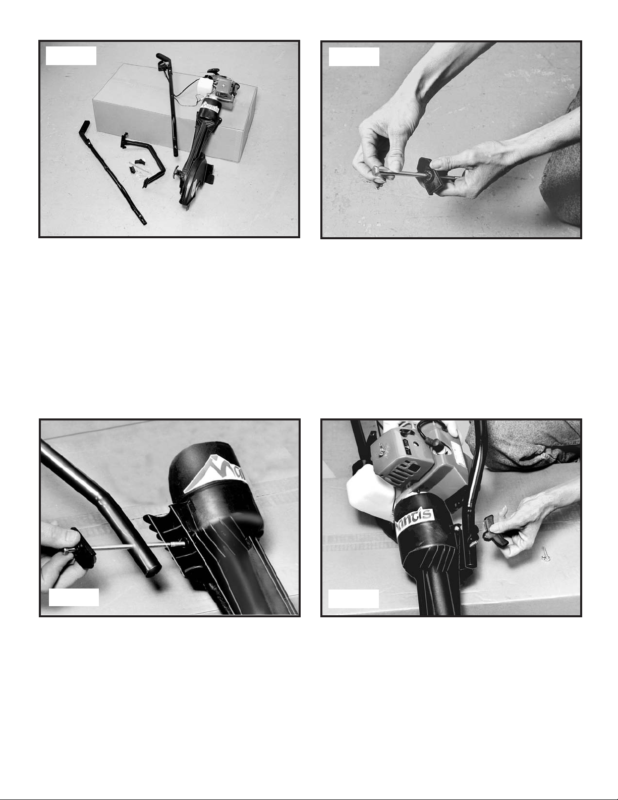
Step 1
Step 2
Step 3
Step 4
Insert the bolt through the right handle (with
the throttle trigger) and through the main
body of the Edger with the point of the plastic washer facing down towards the blades.
After taking all parts out of the carton, turn
the cardboard box over and rest the engine
on top of it for ease of assembly.
Slip the flat handle clamp (key #48) onto the
long bolt (key #52) so that the hex head fits
into the recessed area.
Place the second handle over the bolt that
now protrudes from the other side and secure
it with the large plastic wing nut from the
hardware bag. Do not overtighten the wing
nut.
8
Page 9

Step 5
Step 6
Step 7
Holding the nut in place, tighten the screw
on each side with a flat head screwdriver.
Place the handle cross brace (key #46)
between the handles and lay the throttle
cable and wire into the clips of the righthand handle brace.
Line up the holes in the brace with the holes
in the handle tubing and attach the brace
with one screw (key #1) and one nut (key #2)
on each side.
Your Mantis Edger is now fully assembled!
9
Page 10

Your Mantis Edger comes with a free premeasured bottle of two-cycle engine oil.
Here’s how to mix the oil with the gas.
1. Pour 1/2 gallon of the gasoline into a safe
one gallon container. Do not mix the fuel
and oil in the engine fuel tank.
2. Add the Mantis two-cycle engine oil
(2.6 ounces pre-measured) to the gasoline
and mix. Then add the other 1/2 gallon
of gasoline. (50:1 ratio)
3. Screw the cap onto the gasoline can, and
swirl the can to blend the oil and gas.
4. Carefully pour the fuel mix into the
Mantis Edger’s fuel tank. After putting
the fuel tank’s cap back on, wipe up any
spilled fuel from tank and gasoline can.
IMPORTANT:
Two-cycle fuel separates and ages. Do not
mix more than you will use in a month.
Using old fuel can cause difficult starting
or engine damage. Shake fuel container to
thoroughly mix fuel before each use. Do not
attempt to run your engine on gasoline only;
use the proper fuel mixture.
Fuel Mix and Fueling
WARNING • DANGER
FUEL IS EXTREMELY FLAMMABLE. HANDLE IT WITH CARE. KEEP AWAY FROM
IGNITION SOURCES. DO NOT SMOKE WHILE FUELING YOUR EQUIPMENT.
▲
!
▲
!
Your Mantis Edger is powered by a two-stroke, air cooled
engine which requires a fuel mixture of gasoline and
two-cycle oil.
Use a mixture of 50 parts unleaded regular gasoline and
1 part two-cycle oil (50:1). Use branded 89 octane
(R+M+2) unleaded gasoline or gasohol (max. 10% ethyl
alcohol, or 15% MTBE, no methyl alcohol).
Need more pre-measured engine oil? Contact
your local authorized Mantis dealer.
Remember...
•Always mix two-cycle oil with gasoline
before fueling your edger. Never, ever run
your Edger on gasoline alone. This will ruin
your engine and void all warranties.
• Always use a clean gas can and always use
unleaded gas.
• Never try to mix the oil and gasoline in the
engine fuel tank.
•Always mix gasoline and oil in the proper
proportions: 1 gallon of unleaded gasoline
to 2.6 ounces of two-cycle engine oil.
(50:1 ratio)
IMPORTANT NOTE:
DO NOT use old or stale oil/gasoline
mixture. Always use the proper
oil/ gasoline mixture. If you do not,
your engine will suffer rapid,
permanent damage and you will
void the engine warranty.
10
Page 11

Starting Instructions
To Start Your Mantis Edger for the First Time:
Fill the fuel tank with the proper oil/gasoline mixture
(see previous section). Hand tighten the gasoline cap
until it’s just snug.
Place the start/stop switch into the “start” position
(Picture 1).
Lay the Edger flat on the ground for the following steps.
Pull out the choke button to close the engine choke
(Picture 2).
Locate the purge bulb on the upper right of the
engine, in front of the fuel tank (Picture 3). It sends fuel
into the carburetor for easy starting. Press the purge bulb
until you see fuel flow through the clear fuel return line.
Since you’re starting “cold,” you may need to press six
to eight times. As soon as fuel starts flowing through the
clear fuel line, stop pressing!
Place one foot on the cross-brace, and pull the starter
cord (Picture 4) slowly until resistance is felt. Then give
the recoil starter cord a few short, brisk pulls until the
engine fires. During cold starting, you may need to pull
at least three or four times before the engine fires
(coughs and sputters).
NOTE: When the choke is closed, never pull the cord
more than four or five times. Overpulling may cause
flooding. Also, bear in mind that, when the engine fires,
it only coughs or sputters, and will not run on choke.
Push in the choke button to open the choke (Picture 5)
Then, pull the starter cord again. The engine should
start and run. Let the
engine warm up two to
three minutes before using.
Follow these steps whenever
you are starting the engine
“cold,” or when the engine has
run dry and you have just
added fuel. Remember, always
use short, brisk pulls. Don’t
give the cord a long, forceful
yank. And, do not let the
cord snap back into the
starter housing.
Picture 1
Picture 2
Picture 3
Picture 4
Picture 5
WARNING
AVOID ACCIDENTAL
BLADE ENGAGEMENT
DO NOT SQUEEZE THE
THROTTLE TRIGGER
WHEN STARTING. MAIN-
TAIN PROPER IDLE
SPEED ADJUSTMENT
(3000-3200 RPM).
▲
!
▲
!
11
Page 12

Starting a Warm Engine
Slide start/stop switch to the START position.
Push choke button into the RUN (open) position.
If there is no fuel in the clear return line, push primer
bulb 3-4 times or until fuel is visible in the line.
Pull starter rope using short pulls, 1/2 to 2/3 of the rope
length.
If engine fails to start in 4 pulls, use “First Time” starting
procedure on page 11.
With engine running and both hands on the handles,
squeeze throttle trigger gradually to increase the engine
speed and engage the blade.
Starting Instructions
...continued...
Never use starting
fluids as they will
cause permanent
engine damage. Using
them will void the
engine warranty.
Before you use the
tiller, read the Safety
& Warning rules on
pages 3-5.
Additional Information
WARNING • DANGER
IF ENGINE DOES NOT STOP WHEN SWITCH
IS PUT IN THE STOP POSITION, RELEASE
THE THROTTLE, ALLOW ENGINE TO IDLE.
PUT THE EDGER DOWN AND PULL
THE CHOKE BUTTON OUT TO COLD
START (CLOSED) POSITION.
CHECK AND RETURN START/STOP
SWITCH TO ON POSITION BEFORE
STARTING ENGINE AGAIN.
▲
!
▲
!
won’t turn unless you squeeze the throttle
lever on the handlebars. And, when you
release the throttle lever, the blade will stop.
A Tip for Extending Your
Engine’s Life
After you start your engine, let your edger
warm up for two to three minutes before you
use it. Then, before you put your tiller away,
let it idle for a minute to give the engine a
chance to cool down.
How to Stop
the Engine
Simply push the
start/stop switch
to “stop” (see
picture). This
will stop the
engine instantly.
If it should ever
fail to do so, just pull out the choke button.
The engine will stop at once.
About the Choke
The choke controls the amount of air drawn
into the engine. Your edger will run only
if the choke is open - that is, if the choke
button is pushed in.
A Special Feature (with the idle
set and the engine running)
Even when the engine is running, the blades
12
Page 13

What To Do Just In Case
If you follow the normal starting procedure, you should
have no problem starting your edger. But, just in case you
do have problems, here’s what to do.
Make sure the start/stop switch is on “start.” You’d be surprised how many people forget to slide the switch into the
“start” position.
If the switch was on “stop” when you pulled the cord, you
may have flooded the engine.
Starting a Flooded Engine
• First, examine the spark plug. Use a 3/4 inch spark plug
wrench (Picture 1).
• Remove the cap over the spark plug.
• Unscrew the spark plug (Picture 2).
If the end of the spark plug is wet, the engine may be
flooded. Make sure the switch is in the stop posi-
tion, disconnect spark plug wire and remove plug.
Use a paper towel or a clean rag to dry the spark
plug, then, with the spark plug out of the engine,
pull the starter cord several times. Shake the fuel
out of the inside of the plug and air dry. Next,
replace the spark plug. Use the wrench to tighten it and
replace the cap. Next, put the switch in the start position
and pull the choke button out. Pull the starter cord three
or four times until the engine coughs or sputters. Open the
choke (push the choke button in) and pull the cord a few
times. The engine should start and run.
Picture 1
Picture 2
Picture 3
WARNING
MAKE SURE THE START/STOP SWITCH IS IN THE
STOP POSITION. KEEP PLUG WIRE AWAY FROM
ENGINE TO AVOID UNINTENTIONAL SPARK.
▲
!
▲
!
IMPORTANT NOTE:
To avoid possible damage to the
Threads, do not try to remove the plug
from a hot aluminum cylinder head.
If the end of the spark plug is dry,
check to see if the fuel line is
blocked. The fuel line runs from
the fuel tank to the carburetor. Pull
it off at the carburetor end. Fuel
should drip slowly from the line.
Wipe off any excess or spilled fuel.
If fuel does not drip from the line,
check the line for any bends or
pinches (Picture 3). Kinks in the
line restrict the flow of fuel to the
engine. Just straighten out the line.
Reconnect. Then follow the normal
starting procedure.
13
Page 14

Here’s Another Way to Start
Your Mantis Edger
If you follow the previous steps and your
engine still won’t start, try this:
1. Slide the switch to “start.”
2. Push the choke button to open the choke.
3. Press the plastic bubble 5 to 6 times.
4. Give the starter cord a few short, quick
pulls. The engine should start and run.
5. If the engine does not start, then pull out
the choke button to close the choke. Pull the
starter cord four to five times. The engine
should sputter and cough.
6. After the engine sputters, push the choke
button in. Then pull the starter cord. The
engine should start and run.
What To Do Just In Case ...continued...
7. If the engine still does not start, repeat
steps 2 through 6.
8. If the engine still does not
start, call your local authorized
Mantis Dealer.
IMPORTANT NOTE:
Never use starting fluids as
they will cause permanent
engine damage. Using them
will void the engine warranty.
Before you use the edger, read
the Safety & Warning rules on
pages 3-5.
Edging Instructions
The Mantis Edger is very easy and simple
to use. For some people, it may take a few
edgings to become an expert.
Thoroughly inspect the area where the edger is to be used
and remove all stones, sticks, wires, and other foreign
objects.
Adjust blade height (Picture 1). With a new blade,
try the second hole closest to the operator.
With both arms fully extended downward (Picture 2), hold
both handle grips firmly. With the engine running, pull
the throttle trigger to increase engine speed to full throttle.
Always run the engine at full throttle when edging.
If blade is not deep enough, or if digging is too deep,
adjust blade height or slightly raise or lower handles to
suit depth required. (Picture 3). However, it is always more
comfortable and relaxed to have arms fully extended
downward.
Picture 1
Picture 2
14
Page 15

As cutting actions begins, push the Mantis Edger forward so that the blade can cut the edge as you move forward. (Picture 4).
Continue at a moderate pace until you are familiar with
the controls and the handling of the Mantis Edger.
If blade jams or stops in the ground, lower handles or
pull back unit and recommence (Picture 5). Control
engine and cutting speed to suit work being done When
cutting efficiently, engine speed should be full throttle
under load.
Edging Along a Concrete Edge
For the position of the blade, align the edge guide on
top of the blade cover with the edge of the concrete. If
the blade hits the concrete, lower the handle and reposition the blade at the side of the concrete. Even if the
grass is growing over the concrete and you cannot see
the edge, you can feel the edge of the concrete
with the rotating blade by slightly tilting the
handles of the edger sideways, away from the
concrete, so that the blade tilts towards the concrete and touches or “kisses” the concrete edge
and acts as a guide (Picture 6). Edger blades are
made from high tensile hardened spring steel and will
last a long time. Once the edge is established, the second
and subsequent times around are very fast.
Sideways Tilting
Lower either the left or right handle to achieve angled
cutting along walls or fences (Picture 7).
Picture 3
Picture 4
Picture 5
Picture 6
Picture 7
WARNING
KEEP INSIDE OF BLADE GUARD CLEAN, ESPECIALLY
IN WET CONDITIONS. A CLOGGED GUARD CAN SLOW
DOWN OR STOP BLADE ROTATION AND MAY CAUSE
DAMAGE TO AUTOMATIC SAFETY CLUTCH. ALWAYS
OPERATE BLADE AT FULL THROTTLE WHEN EDGING.
▲
!
▲
!
IMPORTANT NOTE:
The Mantis Edger is equipped with a centrifugal clutch. DO
NOT run edger engine
at low speeds or, if blade is jammed, at
high engine speeds as clutch shoes will
prematurely wear out and cause damage.
15
Page 16

Blade Replacement
1. Stop engine. Unplug the spark plug wire. Clean
area around dust cover and pry debris out with a screwdriver (Picture 1).
2. Through dust cover, place 14mm or 9/16” socket
wrench. On blade end of shaft, place 18mm or adjustable
wrench on blade nut (Picture 2).
3. Unscrew nut counter-clockwise (normal right hand
thread).
4. Remove one small washer, one large washer and two
blades (Picture 3). Before installing blade and washers,
clean all grit and grease. Assemble these parts clean and
dry. Fit large washer, new blades with spiggots of one blade
interlocking with holes on opposite blade, large washer,
two small washers, and nut. Tighten nut.
5. Clean plastic dust cap and housing; press back by gently
tapping into place. Clean inside blade cover of any builtup dirt.
Loose Blade
Follow steps 1 and 2 of Blade Replacement and tighten nut
clockwise.
Picture 1
Picture 2
Picture 3
Picture 4
WARNING
USE ONLY MANTIS BLADES. OTHER BLADES
HAVE LARGER SIZE HOLES (1/2”) WHICH WILL
CAUSE OUT-OF-BALANCE VIBRATIONS WHICH
WILL DAMAGE UNIT AND CAUSE INJURY.
▲
!
▲
!
WARNING
DO NOT RUN ENGINE
WITHOUT BLADE TIGHTENED
TO BLADE SHAFT AS GEAR
DAMAGE WILL OCCUR.
▲
!
▲
!
Lubrication of Gears
There is usually sufficient grease to last at least 4 years or
100 hours of domestic use before topping it up. The grease
in the gear case should be filled up according to use by
adding light, free-flowing grease (available from Mantis,
P/N #9985) through screw hole marked “fill” (Picture 4).
Use a suitable filling gun or squeeze grease pack. Remove
screw marked “bleed.” Squeeze in 3-4 pumps of grease,
until it comes out of the bleed hole. Refit fill screw.
NOTE: Do not use light or heavy gear oil as
it might leak out. If gear case shows leakage,
tighten all screws or replace O-ring. Refill casing.
16
Page 17

Maintenance
Check the Air Filter Often
A wet or dirty air filter can affect the way your engine
starts, performs, and wears. So, it’s a good idea to check
your air filter at least once a month.
If you work in dusty soil, or if you want to be on the
safe side - then check your filter more often (for
instance, before each use). But be sure to replace it at
least once a year, in the spring or fall. Clean or change
it as needed. It is recommended to change the air filter
yearly.
How to Check, Clean, and Change the Air Filter
1. Loosen the wing nut on the side of the air-cleaner
cover (Picture 1).
2. Take off the cover. Make sure to clear the choke
button (Picture 2).
3. The air filter is the felt pad on the inside of the
air-cleaner cover. Check whether it is soiled or moist.
4. If the air filter needs cleaning or no longer fits
properly, remove it. Just lift an edge carefully and “peel”
it out (Picture 3).
5. Use a brush to remove debris from the pad.
6. If the air filter is so dirty that it won’t come clean,
you must replace it or severe engine damage will occur.
Contact your local authorized Mantis dealer.
7. Insert your clean filter inside the air-cleaner cover.
Installing the filter incorrectly will cause engine damage
and void the warranty. Fit the cover back over the air
cleaner (Again, make sure to clear the choke button).
8. Tighten the wing nut to secure the cover.
Picture 1
Picture 2
Picture 3
IMPORTANT!
Make sure filter is “seated” properly in
the cover. The filter must fit snugly inside
the rim that holds the filter into place.
IMPORTANT NOTE:
Please check the lip
on the Air Cleaner
Cover. If the lip is
chipped or cracked, it
should be replaced. This
will prevent dirt from
being ingested through
the carburetor into the
inside of the engine.
17
Page 18

Maintenance ...continued...
Clear Blockages From the Fuel Line and Filter
After you’ve used your Edger for a few seasons, check for
blockages in the fuel tank and fuel filter. Such blockages
can keep your Edger from starting.
Clear any blockages you see in the tank, fuel filter, or
fuel line. Remember: The fuel filter is located inside the
tank (Picture 1). Then, use the normal starting procedure
to start your Edger.
What To Do If Your Engine Idles Too High
What if your engine runs too fast...or if the blades
turn the instant you start the Edger? You may need
to adjust the idle screw ( Picture 2, or Key #25 under
“Carburetor” on page 28) by itself, right below the H
and L screws. Gently turn it counter-clockwise. You’ll
know you’ve adjusted it correctly when the blade does
not turn at low idle.
If you continue to have idle problems, you may need to
adjust the throttle cable.
First, locate the metal triangle at the end of the throttle
cable (Picture 2). The idle screw must touch this triangle.
But, if the throttle cable’s too tight, you’ll see a gap
between the idle screw and the triangle.
To fix this, loosen the top nut that holds the throttle
cable in place (Picture 3) (Use a 10mm wrench or an
adjustable wrench). Then, slide the cable down until you
close the gap between the triangle and the idle screw
(Picture 4). Now, tighten the bottom nut that holds the
throttle cable.
Locate the metal “button” on the triangle. This is the
swivel. The large end of the throttle cable must be inside
the slot in this swivel (Picture 4).
Picture 1
Picture 2
Picture 3
Picture 4
18
idle screw
Page 19

What To Do If Your Engine
Runs “Rough”
If your engine runs “rough” or stalls, you
may need to adjust the carburetor and idle
screws.
If you remove the air-cleaner cover, you’ll see
the two carburetor adjustment screws, next
to the black choke button.
The “RED” screw is the HIGH-speed adjustment...The “WHITE” screw is the low speed
adjustment.
Start the engine and let it run for two to
three minutes. “FLASH” the choke several
times during the warm-up to clear any air
from the fuel system.
Then, stop the engine after it reaches operating temperature.
Now, turn the RED, high-speed screw counter-clockwise all the way to the stop...Then,
turn the WHITE, low-speed screw halfway
between the counter-clockwise and clockwise
stop positions.
Now restart the engine to finish the carburetor adjustment.
Run the engine at full speed two or three
seconds to clear out any excess fuel. Then
return to idle.
Now, accelerate the engine to full throttle
several times to check for a smooth transition
from idle to high speed.
If the engine hesitates, turn the WHITE, lowspeed screw counter-clockwise one-eighth of
a turn. Then, accelerate the engine.
Repeat the adjustment until you get a
smooth transition to high speed.
Cleaning the Muffler Screen
1. Take out the spark plug.
2. Remove the red cylinder cover (Key #19)
which is held on by two Phillips-head screws.
(Key #18).
3. You will see the metal screen fixture, held
on by 3 more Phillips-head screws (Key #26).
Remove the fixture.
4. Behind the fixture (Key #25) will be the
muffler lid (Key #24) and muffler lid gasket
(Key #23). The screen sits in the gasket.
5. If the screen (Key #22) is clogged with
deposits, it needs to be cleaned. Use carburetor cleaner, and any brush that is not metal.
Brush the screen until you are able to see
through it.
6. If the screen remains plugged after
attempts at cleaning, it must be replaced.
Maintenance
...continued...
19
Page 20

Storage
Each fall - or before you store your Mantis Edger for any
long period - be sure to take these measures:
1. Do not store your Edger with fuel still in it. Even under
ideal conditions, stored fuel containing ethanol or MTBE
can start to go stale in 30 days. And, since stale fuel has a
high gum content, it can clog the carburetor, which will,
in turn, restrict fuel flow. So, when you’re ready to
store your Edger, or will not be using it for more
than 2 weeks, drain the fuel tank completely. (Picture 2).
2. Next, restart the engine to make sure no fuel is left in
the carburetor. Then run the engine until it stops. This will
prevent gum deposits forming inside of the carburetor and
possible engine damage..
3. Disconnect the spark plug wire and remove the spark
plug. (Use a 19mm or 3/4” spark plug wrench.) Pour about
a teaspoon of clean, air-cooled oil through the spark plug
hole into the combustion chamber (Picture 3). Slowly pull
the starter cord two or three times to coat the inside of the
cylinder wall.
4. Inspect the spark plug and, if necessary, clean it. If you
need to replace it, buy a NGK-BPM7Y.
5. Install the spark plug, but leave the spark plug wire
disconnected.
6. Clean the air filter as described on page 17.
7. Clean dirt, grass, and other materials from the entire
machine.
8. Wipe the blade with oil or spray it with WD-40 to
prevent rusting.
9. Oil the throttle cable and all visible moving parts
(Do not remove the engine cover).
Picture 1
Picture 2
Picture 3
WARNING
DO NOT STORE IN AN AREA WHERE FUEL FUMES MAY
ACCUMULATE AND REACH A FLAME OR SPARK
▲
!
▲
!
20
Page 21

Storage ...continued...
10. Order new parts to replace any that are badly worn
or broken. Just contact your local authorized Mantis dealer.
But do it early, so you’ll have the parts well before the next
season.
11. Store your Edger - in an upright position - in a clean,
dry place (Picture 1, previous page).
12. Do you have any fuel left over from last season?
Dispose of it properly. Buy fresh oil and gasoline next
season.
How to Prepare Your Mantis Edger for Restarting
In the spring, when you take your Edger out of storage,
remove the spark plug. Pull the starter cord three or four
times to clean oil from the combustion chamber (Picture
1). Wipe oil from the spark plug. Place the spark plug back
into the cylinder. Re-connect the spark plug wire back on
the spark plug. Then, follow on steps on pages 10 and 11
to refuel and restart your Edger.
Again, Check the Carburetor
If your Edger won’t restart in the spring - or if it lacks its
usual power - the carburetor may need attention. Follow
the steps on page 18 for adjusting the H and L screws
(Picture 2).
Check the Spark Plug Too
If your Edger won’t restart or if it lacks full power, the
spark plug may be at fault. Check to see if the plug is
fouled with oily black deposits. Clean or replace it if it is.
(Picture 3).
Also, check whether the center electrode is rounded at the
end, or if the ground electrode is worn. If either is the case,
you should replace it with a NGK-BPM7Y spark plug. Use a
19mm or a 3/4” spark plug wrench to install it. Adjust the
plug gap .025 to .028 inches (0.6 to 0.7 mm).
Caution: Do not overtighten the spark plug.
The correct torque is 18 to 22 ft.-lbs. (24-30 n.m.).
Picture 1
Picture 2
Picture 3
IMPORTANT NOTE:
To avoid possible damage to the threads, do
not try to remove the
plug from a hot aluminum cylinder head.
21
Page 22

Troubleshooting Tips
Problem
Engine fails to start
Engine hard to start.
Engine misses.
Engine overheats.
Cause
Start/Stop switch is in Stop
position.
No fuel in tank.
Fuel strainer clogged.
Fuel line clogged.
Spark plug shorted or fouled.
Spark plug is broken (cracked
porcelain or electrodes broken)
Ignition lead wire shorted, broken
or disconnected from spark plug.
Ignition inoperative.
Water in gasoline or stale fuel
mixture.
Too much oil in fuel mixture.
Engine under or over choked.
Carburetor out of adjustment.
Gasket leaks (carburetor or cylinder
base gasket).
Weak spark at spark plug.
Dirt in fuel line or carburetor.
Carburetor improperly adjusted.
Spark plug fouled, broken, or
incorrect gap setting.
Weak or intermittent spark at
spark plug.
Insufficient oil in fuel mixture.
Air flow obstructed.
Solution
Move switch to start.
Fill tank
Replace strainer.
Clean fuel line.
Install new spark plug.
Replace spark plug.
Replace lead wire or attach to
spark plug.
Contact your nearest
Authorized Mantis Dealer
Drain entire system and refill
with fresh fuel.
Drain and refill with correct
mixture.
If flooded by overchoking,
proceed according to instructions in operation section. If
underchoked, move choke
lever to closed position and
crank two or three times.
See “Carburetor Adjustment”.
Replace gaskets.
Contact nearest Authorized
Mantis Dealer.
Remove and clean.
See “Carburetor Adjustment”.
Clean or replace spark plug -
set gap to .024-.028 in.
(0.6-0.7mm)
Contact your nearest
Authorized Mantis Dealer.
Mix fuel as described in
starting instructions.
Clean flywheel cylinder fins
and screen.
22
Page 23

Solution
Clean or replace air filter.
See “Carburetor Adjustment.”
Clean carbon from muffler.
Remove muffler, rotate engine
until the piston is at top of
cylinder. With a wooden
scraper or blunt tool, remove
all carbon from exhaust
ports. Be careful not to
scratch or damage piston
or cylinder walls. Blow out
all loose carbon with com-
pressed air. Install muffler
and gasket.
Clean Spark Arrestor.
Contact nearest Authorized
Mantis Dealer.
Replace with plugs specified for
engine.
Contact nearest Authorized
Mantis Dealer.
See “Carburetor Adjustment.”
Remove dust and dirt from
between fins.
Clean.
Cut less deep. Check that
blades are rotating. Edge at
full throttle.
Tighten bladenut.
Push choke to OFF position.
Tighten screws.
Replace O-ring.
Refill with correct grade grease.
See page X.
Refill with lubricant.
Reassembly parts correctly.
Cause
Air filter clogged.
Carburetor out of adjustment.
Muffler clogged.
Clogged exhaust ports.
Spark Arrestor clogged.
Poor compression.
Spark plugs in incorrect heat range.
Bearings, piston ring or cylinder
walls are worn.
Carburetor adjustment too “lean.”
Engine overheats.
Blade cover filled with dirt/grass.
Clutch slipping.
Loose bladenut.
Choke partly on.
Loose screws.
Broken O-ring.
Grease too thin or oil used.
No lubricant in gearcase.
Loose bladenut or gear adjustment
incorrect.
Problem
Engine lacks power.
Engine noisy or
knocking.
Engine stalls under
load.
Cutting blade does not
turn when operating.
Gear case leaking.
Noisy gears.
Troubleshooting Tips
...continued...
23
Page 24

Engine Specifications
Dry Weight
Type of Engine
Rotation
Bore
Stroke
Spark Plug
Fuel
Fuel Oil Ratio
Gasoline
Displacement
Exhaust System
Carburetor
Ignition System
Starter
Oil
Fuel Tank Capacity
Starter System Clutch
2.5kg - 5 lbs., 10 ounces
Air cooled, two stroke, single cylinder, gasoline engine
Clockwise, viewed from TOP
32.2 mm (1.268 inches)
26.0 mm (1.04 inches)
NGK BPM7Y
Premixed two stroke fuel
50:1 ratio with Mantis oil
Unleaded (see page X)
21.2 cc (1.294 cu. in.)
Spark arrestor muffler
ZAMA diaphragm model C1U type
Flywheel magneto, capacitor discharge ignition type
Automatic rewind type
Designated, two-stroke, air-cooled engine oil
0.4 liter (13.57 oz.)
Automatic rewind starter Centrifugal type
Service Maintenance Guide
Frequency
Daily or every 4 hours of use
Every 3 months or 100 hours of use
Every 3 months of 100 hours of use
6 months or 300 hours of use
6 months or 300 hours of use
Yearly or 600 hours of use*
Before use
Monthly
Yearly
After Use
Before Use
Before Use
Before Use
Before Use
Before Use
Monthly
Monthly
Every 3 months or 100 hours of use
With each refueling
No maintenance
For coil and flywheel
Maintenance
Clean
Replace
Clean
Replace
Check/Rebuild
Replace
Inspect/Clean
Inspect/Clean
Check Grease
Inspect/Clean/Lubricate
Inspect/Repair
Inspect/Tighten/Replace
Inspect/Replace
Inspect/Replace
Inspect/Replace
Inspect/Replace
Inspect/Replace
Replace
Check
Clean
Replace
Area
Air Filter
Spark Plug
Carburetor
Cooling System
Muffler (Spark Arrestor)
Gear Housing
Blades
Fuel Leaks
Fasteners
Labels
Handles
Guards/Safety Devices
Fuel Line
Starter Rope
Fuel Strainer
Choke
Ignition System
24
Page 25

NOTES:
25
Page 26

26
MANTIS EDGER PARTS LIST
KEY # PART # DESCRIPTION
33 100217 Blade Cover Lid
34 100218 Wheel
35 100219 Wheel Arm
36 100220 Height Adjustment Pin
37 100221 Handle Height Adjustment
38 100222 Shield Edger Body
39 100529 Screw 5.5mm
41 100223 Wheel Bushing RH
42 100224 Wheel Bushing LH
43 100531 Nut Clutch Drum
44 100225 Handle Right
45 100226 Handle Left
46 100227 Handle Cross Brace
47 100228 Throttle Trigger assembly
48 100532 Handle Clamp
49 100229 Grip Right Handle w/o Throttle
50 100230 Housing Throttle
51 100231 Grip Left Handle
52 100533 Bolt 1/4” x 5.5"
53 100232 Knob
54 100233 Main Shaft
55 100234 Main Body
56 100235 Clutch Housing
57 100236 Dust Plug
58 100702 Instruction Book Mailorder
59 100237 Switch Wire
61 100601 Motor Warning Label
62 100200 Throttle Cable
63 4078 Nut Jam M6 Hex
64 4079 Washer Lock Internal M6
65 380E-4B1E Engine
66 100608 Mantis Edger Label
KEY # PART # DESCRIPTION
1 100500 Screw M5 x 36mm
2 100501 Nut Nyloc 5mm
3 100100 Bearing with seal 12 x 32 x 10
4 100101 “O” ring 64 x 1.75mm
5 9985 Grease
6 100102 Felt Seal
7 100203 Blades, Mantis Edger
8 100108 Blade Drum
9 100109 Blade Shaft Drive
10 100506 Blade Washer Small
11 100507 Blade Washer Large
12 100111 Crown Gear Spacer
13 100602 Warning Label “Blade Cover” (P)
14 100603 Warning Label Handle (P)
15 100513 Nut M12 x 1.75
16 100122 Pinion L/E
17 100515 Screw M5 x 39 S/thread
18 100521 Self Screw Thread M5 x 19
19 100204 Spring Throttle Lock
20 100205 Spring Throttle Trigger
21 100206 Tab Connector 45 degree
22 100534 Washer Pinion .050
23 100208 Gear, Crown
24 100209 Trigger Throttle
25 100210 Throttle Interlock
26 100211 Switch Slide
27 100212 Spring Adj. Arm
28 100528 Washer Wheel Arm
29 100213 Debris Deflector
30 100214 Spring Debris Deflector
31 100215 Debris Deflector Limiter
32 100216 Blade and Bearing Cover
NOTE: Please use the Part No.
when ordering any parts
Page 27

39
37
27
36
31
12
10
39
17
28
15
7
39
50
20
19
33
39
32
52
39
x6
13
48
13
45
44
59
39
1
14
49
1
51
43
47#
56
35
57
38
9
55
3
3
23
4
25
#47
5
58
24
26
6
21
2
2
46
8
11
41
34
42
29
53
54
3
3
1
1
22
16
2
30
39
10
18
10
2
11
MANTIS EDGER PARTS BREAKDOWN
27
63
64
62
66
66
65
61
Page 28

SV-4B1E Engine Parts
Carburetor
Air Cleaner & Muffler
28
KEY PART QTY DESCRIPTION
NO. NO.
12520013122 1 Carburetor Asy
Includes the following:
1 12534405360 2 Screw
2 12536308560 1 Ring
3 12538108660 1 Pump, Purge
4 12531005360 2 Screw
5 12538305360 1 Base, Purge
6A B1Diaphragm, Metering
7A B1Gasket, Metering
8 12533942030 1 Screw
9A 1Pen, Metering Arm
10 A 1 Lever, Metering
11 A 1 Spring, Metering Lever
12 A 1 Valve, Inlet Needle
13 A 1 Plug, Welch
14 12531649030 1 Valve, Throttle
15 12531413930 1 Screw
16 12531813120 1 Needle, Low Speed
17 12532909860 1 Cap, Limiter L.L.
18 12532013310 1 Needle, High Speed
19 12532939030 1 Cap, Limiter H.S.
20 12532713930 1 Clip
KEY PART QTY DESCRIPTION
NO. NO.
21 12537242030 1 Swivel
22 12531713310 1 Shaft, Throttle
23 12531342030 1 Spring, Throttle Return
24 12537813930 1 Piece, Friction
25 12533306960 1 Screw, Idle Adjust
26 12533306960 2 Screw
27 12532412820 1 Cover, Pump
28 A B 1 Gasket, Fuel Pump
29 A B 1 Diaphragm, Fuel Pump
30 A 1 Strainer
31 12537649030 1 Nozzle, Main Check Valve
32 12532715130 1 Clip
33 12533406560 1 Spring, Adjust Screw
A 12530012820 1 Rebuild Kit
B 12530320560 1 Gasket/Diaphragm Kit
KEY PART QTY DESCRIPTION
NO. NO.
1 13001042032 1 Gasket, Intake
2 90023805020 2 Screw 5 x 20
3 17851004560 1 Rod, Choke
4 13030104560 1 Case, Air Cleaner
5 17881005230 1 Grommet
6 13041005360 1 Bracket, Air Cleaner
7 90024205057 2 Screw 5 x 57
8 89012140630 1 Label, Choke
9 90052800005 1 Nut, Wing
10 13032611521 1 Cover, Air Cleaner
11 13031004560 1 Filter, Air
12 17851504560 1 Shutter, Choke
13 17851600830 1 Spacer
14 12520013122 1 Carburetor Assy
15 13001642031 1 Gasket, Intake
KEY PART QTY DESCRIPTION
NO. NO.
16 13001742031 1 Insulator
17 90050000005 2 Nut 5
20 14580011821 1 Muffler Asy
(Includes Items 21-26)
21 14551042031 2 Gasket, Muffler
(Included In Kit 88900045131)
22 14586240630 1 Screen, Muffler
23 14586642031 1 Gasket, Muffler Lid
(Included In Kit 88900045131)
24 14587642030 1 Lid, Muffler
25 14586306960 1 Fixture, Screen
26 90024204010 3 Screw 4 x 10
27 90010505050 2 Bolt 5 x 50
28 90060000005 2 Washer 5
29 14587105360 1 Cover, Muffler
NOTE: Please use the Part No.
when ordering any parts
Page 29

SV-4B1E Engine
Fuel Tank
Block
Starter, Pawl Catcher & Clutch
29
KEY PART QTY DESCRIPTION
NO. NO.
18 90027505015 3 Screws 5x15
19 90060300005 3 Washers
20 13100511820 1 Tank, Fuel
21 13201011520 1 Pipe 3x5x210
22 13130056430 1Valve, Check
23 13011100530 1 Clip, Pipe
24 13131244330 1 Pipe 3x 5x 70
25 13201049030 1 Pipe 3x6x50
26 13211546730 1 Grommet, Fuel
27 13201309820 1 Clip
28 13120507320 1 Strainer, Fuel
29 13100453530 1 Cap Asy, Fuel Tank
(Includes Item 30)
30 13101655830 1 Gasket, Fuel Cap
KEY PART QTY DESCRIPTION
NO. NO.
1 177200 12820 1 Starter Asy
2 17722042030 1 Spring, Rewind
3 17721544430 1 Drum, Starter
4 17723644330 1 Screw
51Rope Starter
(Use Bulk Rope
99944400040
3 x 890 (.12 x 33.5)
6 17722742030 1 Guide, Rope
7 17728811120 1 Grip, Starter
8 90023804016 4 Screw 4x16
9 90060500008 1 Washer, Spring 8
10 90016204022 2 Bolt 4 x 22
11 15660152130 1 Coil, Ignition
12 99944500071 1 Spark Plug BPM-7Y
13 15901103432 1 Coil, Spark Plug
14 15901201620 1 Cap, Spark Plug
15 15611004920 1 Bushing
16 15680105360 1 Flywheel
17 17720212220 1 Pawl Asy, Starter
(Includes Items 18 & 19)
18 17723442030 2 Spring, Pawl Return
19 17721844330 2 Pawl, Starter
20 90060000005 1 Washer 5
21 90060500005 1 Washer, Spring 5
22 90011505025 1 Bolt 5x25
23 90023804014 4 Screw 4x14
24 61022311520 1 Case Clutch
25 17501004633 1 Drum, Clutch
26 90023806012 1 Screw 6x12
27 17501411520 1 Washer, Clutch
28 17504404630 1 Washer, Clutch
29 90080836000 1 Bearing, Ball 6000
30 90060000010 1 Washer 10
31 17501904630 1 Plate, Clutch
32 17500007531 1 Clutch Asy
(Includes Items 33-35)
33 17500905131 2 Shoe, Clutch
34 17501805130 2 Spring, Clutch
35 17501605020 1 Hub, Clutch
36 16202152830 1 Lead, Ignition
KEY PART QTY DESCRIPTION
NO. NO.
1 10020411520 1Crankcase kit
(Includes Items 2-6)
2 10021242030 2 Seal, Oil
3 10021503930 2 Pin, Dowel
41Gasket, Crankcase
(Included in Kit 88900045131)
5 90081036201 2 Bearing, Ball 620
6 90016205028 3 Bolt 5x28
7 10010013120 1Crankshaft Asy
8 61032502730 1 Key, Woodruff
9 10000048732 1 Piston, Kit
(Includes Items 10-14)
10 10001105330 2 Ring, Piston
11 10001504630 2 Circlip, Piston Pin
12 10001411520 2 Spacer, Piston Pin
13 10001251230 1 Bearing, Needle
14 10001311520 1 Pin, Piston
15 10101044332 1 Gasket, Cylinder Base
(Included in Kit 889000045131)
16 10101106562 1 Cylinder
17 90016205022 2 Bolt 5x22
18 90023804018 2 Screw 4x18
19 10150612820 1Cover, Cylinder
NOTE: Please use the Part No.
when ordering any parts
Page 30

NOTES:
30
Page 31

31
NOTES:
Page 32

LIMITED WARRANT Y INFORMATION
FOR THE MANTIS EDGER
MANTIS extends only to the original
consumer purchaser a limited warranty
against defects in materials and workmanship for a period of two years from
date of purchase. This warranty covers
all portions of the MANTIS Edger.
MANTIS will repair or, at its option,
replace any defective part or parts of the
product free of charge. In the event of
a defect or malfunction, the purchaser
must return the product to an authorized
Mantis dealer.
MANTIS assumes no responsibility in
the event that the product was assembled
or used in contravention of any assembly,
care, safety, or operating instructions
contained in the Owner’s Manual; was not
used with reasonable care; or was used for
other than normal and intended purposes.
MANTIS MAKES NO EXPRESS WARRANTIES
OR REPRESENTATION EXCEPT THOSE
CONTAINED HEREIN. THE DURATION OF
ANY IMPLIED WARRANTY, INCLUDING
MERCHANTABILITY AND FITNESS FOR A
PARTICULAR PURPOSE, IS LIMITED TO THE
DURATION OF THE EXPRESS WARRANTY.
MANTIS DISCLAIMS ALL LIABILITY FOR
INDIRECT AND/OR CONSEQUENTIAL
DAMAGES. SOME STATES DO NOT ALLOW
LIMITATIONS ON HOW LONG AN IMPLIED
WARRANTY LASTS AND/ OR DO NOT
ALLOW THE EXCLUSION OR LIMITATION
OF INCIDENTAL OR CONSEQUENTIAL
DAMAGES, SO THAT ABOVE LIMITATIONS
AND EXCLUSIONS MAY NOT APPLY TO
YOU. THIS WARRANTY GIVES YOU SPECIFIC LEGAL RIGHTS, AND YOU MAY ALSO
HAVE OTHER RIGHTS WHICH VARY FROM
STATE TO STATE.
MANTIS
1028 Street Road
Southampton, PA 18966
(215) 355-9700
Specifications, descriptions, and illustrative material in this literature are as accurate as known at the time of publication, but are subject to change without notice.
P/N 100707
©MANTIS 5/00
Printed in USA
 Loading...