

Page 1

© 2004 Little Wonder, Div. of Schiller-Pfeiffer Inc. All Rights Reserved.
ASPIRADORA DE ALTO RENDIMIENTO
ASPIRATEUR HAUTE PERFORMANCE
© 2004 Little Wonder, Division de Schiller Pfeiffer Inc. Tous droits réservés.
© 2004 Little Wonder, División de Schiller - Pfeiffer, Inc. Todos los Derechos Reservados.
Models 5601 and 5611
Modèles 5601 et 5611
Modelos 5601 y 5611
Page 2

Page 3
1
Table of Contents Important Information
A. Introduction
On behalf of everyone at
Little Wonder
, we would like to
thank you for your purchase of a
Little Wonder
High
Performance Vac. This professional debris handling machine
was designed to the highest standards to ensure you many
hours of uninterrupted service.
This manual provides the information necessary for safe and
efficient operation and service. For your safety, it is critically
important that you read and understand this entire manual
before operating your High Performance Vac.
Specifications:
Model Dry Weight Max Rpm
5601 182 lbs. 3400
5611 184 lbs. 3400
B. Service Information
High Performance Vac Unit
Contact your local
Little Wonder
dealer.
Engine
Contact an authorized Briggs & Stratton dealer. Dealers are
listed in the Yellow Pages under “Lawn and Garden Equipment
Supplies”, “Lawn Maintenance” or “Lawn Mowers”. Your
dealer will need to know the model and serial number of your
engine. For their location, please consult the operator’s manual
provided with your engine.
C. Special Safety Information
WARNING DANGER
ATTENTION: THIS SYMBOL POINTS OUT
IMPORTANT SAFETY INSTRUCTIONS
WHEN YOU SEE THIS SYMBOL
HEED ITS WARNING! STAY ALERT!
WARNING DANGER
TO REDUCE THE POTENTIAL FOR ACCIDENTS,
COMPLY WITH THE SAFETY INSTRUCTIONS IN
THIS MANUAL. FAILURE TO COMPLY MAY RESULT
IN SERIOUS PERSONAL INJURY AND OR
EQUIPMENT AND PROPERTY DAMAGE.
WARNING DANGER
THE ENGINE EXHAUST FROM THIS PRODUCT
CONTAINS CHEMICALS KNOWN TO THE STATE OF
CALIFORNIA TO CAUSE CANCER, BIRTH DEFECTS
OR OTHER REPRODUCTIVE HARM.
Important Information
Introduction . . . . . . . . . . . . . . . . . . . . . . . . . . . .1
Service Information . . . . . . . . . . . . . . . . . . . . .1
Special Safety Information . . . . . . . . . . . . . . . .1
Unpackaging
Unpackaging Information . . . . . . . . . . . . . . . . .2
Safety and Warnings
Safety Decals . . . . . . . . . . . . . . . . . . . . . . . . .2-3
General Safety Rules
Warnings - "Don’ts" . . . . . . . . . . . . . . . . . . . . .4
Warnings - "Do’s" . . . . . . . . . . . . . . . . . . . . .4-5
Engine/ Fuel Warnings - "Don’ts" . . . . . . . . . .5
Engine/ Fuel Warnings - "Do’s" . . . . . . . . . . . .5
Assembly Instructions
Assembly . . . . . . . . . . . . . . . . . . . . . . . . . . . . . .6
Put Oil and Gasoline in Engine
Before Starting . . . . . . . . . . . . . . . . . . . . . . . . .7
Use of Lifting Lug . . . . . . . . . . . . . . . . . . . . . .7
Operation
Start Engine . . . . . . . . . . . . . . . . . . . . . . . . . . . .7
Vacuuming . . . . . . . . . . . . . . . . . . . . . . . . . . . .7
Empty Debris Bag . . . . . . . . . . . . . . . . . . . . . . .7
Refueling the Engine . . . . . . . . . . . . . . . . . . . .7
Storage and Maintenance
Storage . . . . . . . . . . . . . . . . . . . . . . . . . . . . . . .8
Maintenance . . . . . . . . . . . . . . . . . . . . . . . . . . .8
Removing Blockage in Moving Parts . . . . . . . .9
Removing the Fan . . . . . . . . . . . . . . . . . . . . . . .9
Part Numbers
HPV Assembly Part Numbers . . . . . . . . . . . .10
HPV Subassembly Part Numbers . . . . . . .11-12
Warranties
Warranty . . . . . . . . . . . . . . . . . . . . . .Back cover
Page 4
2
Unpacking
1. Remove Collector assembly, Nozzle assembly, and
Debris bag from the top section of the package.
2. Remove cardboard insert.
3. Cut away short side of box and fold down.
4. Roll HPV base unit out of box.
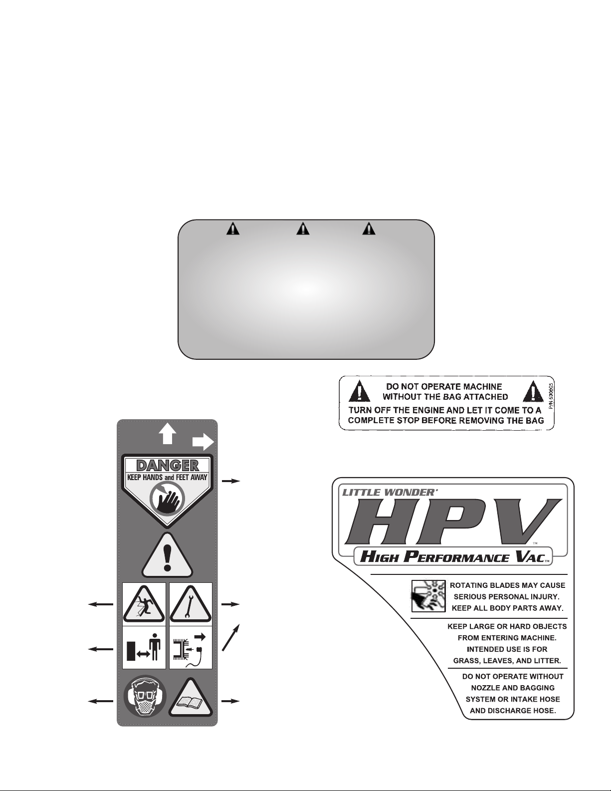
P/N 600602
Warning Label
P/N 600605
Warning Label
Caution:
Thrown
objects.
Keep
bystanders
away.
Always wear
eye, ear and
breathing
protection.
Before
performing
any service or
maintenance,
disconnect spark
plug wire. Make
sure throttle is in
STOP position.
Read and
understand the
Owners Manual.
Store your
Owners Manual
in a safe place.
Keep hands and
feet away from
air discharge
areas. Rotating
fan will cause
serious injury.
Safety and Warnings
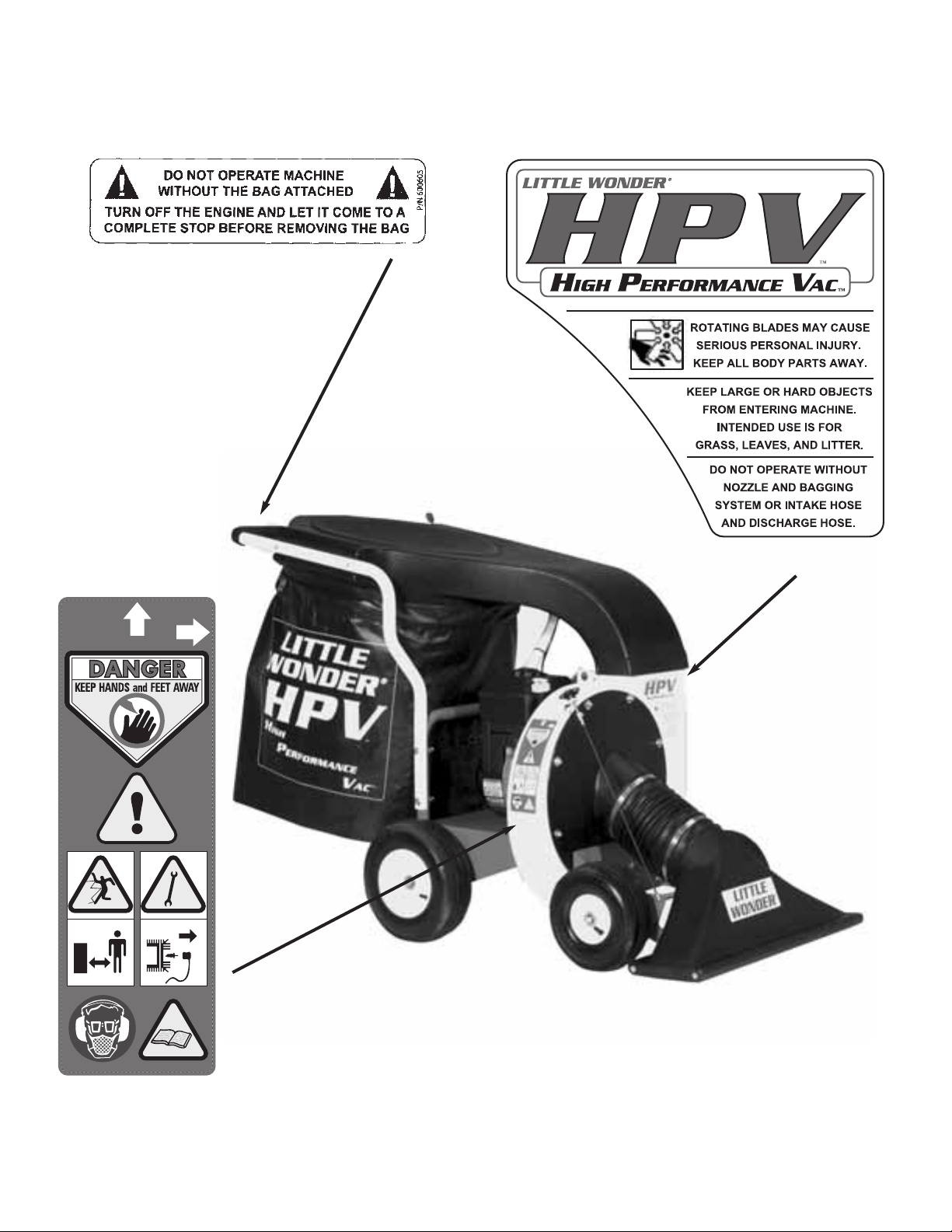
A. Safety Decals
An important part of the safety system incorporated in this
High Performance Vac are the warnings and informational
decals (labels) found on various parts of the unit.
These decals (labels) must be replaced if they become illegible
due to abrasion, etc.
It is your responsibility to replace the decals (labels) when they
become hard to read. The location of these decals and their
part numbers for ordering are shown on page 3.
WARNING DANGER
IMPROPER USE OR CARE OF THIS HIGH
PERFORMANCE VAC, OR FAILURE TO WEAR PROPER
PROTECTION CAN RESULT IN SERIOUS INJURY.
READ AND UNDERSTAND THE RULES FOR
SAFE OPERATION AND ALL INSTRUCTIONS
IN THIS MANUAL.
WEAR HEARING, EYE, AND BREATHING
PROTECTION.
P/N 600604
Page 5
3
P/N 600604
Safety and Warnings
P/N 600602
Warning Label
P/N 600605
Warning Label
Page 6
4
General Safety Rules
1. Read and understand manual.
2. Wear eye, hearing, and breathing protection, proper
clothing and footwear.
3. While operating the machine always be sure of a safe and
secure operating position, maintain a firm footing and
good balance at all times.
4. Keep area clear of children, pets and bystanders.
5. Never attempt to use an incomplete machine or one fitted
with an unauthorized modification.
6. Avoid contact with and inhalation of harmful fluids, gases,
mists, fumes, and dust.
7. Do not allow children to operate machine.
8. Do not override or remove any safety devices.
12. Keep hands away from hose inlet and discharge chute.
13. Disconnect spark plug before doing any cleaning or
maintenance.
14. Wear gloves to protect your hands.
15. Beware that the machine is loud and, during normal
operation; may interfere with speech communication.
A. Warnings - "Don’ts"
Don’t attempt to remove materials from intake or discharge
when High Performance Vac is running, or fan is rotating.
Don’t install or remove components while High Performance
Vac is running. Turn off engine to make changeover. Be sure
throttle is in the stop position, and the High Performance Vac
has come to a complete stop. Remove the spark plug wire
from the spark plug before removing material.
Don’t attempt to repair High Performance Vac. Have repairs
made by qualified Little Wonder dealer or repairman. See that
only Little Wonder and recommended engine manufacturers
replacement parts are used.
Don’t leave the engine running while the High Performance
Vac is unattended.
Don’t store, spill, or use gasoline near flames or spark
B. Warnings - "Do’s"
Always dress properly. Do not wear loose clothing or jewelry.
They can be caught in moving parts. Use of sturdy gloves,
non-skid footwear and safety glasses are recommended.
Always wear ear protectors where possible. Use face filter to
avoid breathing dust.
Always stay alert. Watch what you are doing and use common
sense. Do not operate High Performance Vac when fatigued.
Always keep hands away from air intake and air outlet chute.
Keep both hands on handles when power is on.
Always maintain and examine High Performance Vac with
care. Follow maintenance instructions given in manual.
WARNING DANGER
9. FAN COASTS AFTER THE ENGINE IS TURNED OFF.
WARNING DANGER
DO NOT SMOKE WHEN FILLING FUEL TANK
WARNING DANGER
10. ROTATING FAN. DON’T ATTEMPT TO REMOVE
MATERIALS FROM INTAKE OR DISCHARGE WHEN
UNIT IS RUNNING, OR FAN IS ROTATING.
WARNING DANGER
DO NOT USE THE HIGH PERFORMANCE VAC IF THE
MUFFLER IS DEFECTIVE OR MISSING.
WARNING DANGER
11. DO NOT OPERATE UNIT IF EXCESSIVE VIBRATION
OCCURS; SHUT ENGINE OFF IMMEDIATELY!
REMOVE SPARK PLUG WIRES AND CHECK FOR
DAMAGED IMPELLER, LOOSE IMPELLER BOLT,
LOOSE IMPELLER KEY, OR LODGED
FOREIGN OBJECTS.
Page 7
5
WARNING DANGER
IF THE HIGH PERFORMANCE VAC IS USED
IMPROPERLY OR SAFETY PRECAUTIONS ARE NOT
FOLLOWED, THE USER RISKS SERIOUS INJURY TO
THEMSELVES AND OTHERS.
READ AND UNDERSTAND THE FOLLOWING
BEFORE ATTEMPTING TO OPERATE THIS
HIGH PERFORMANCE VAC.
WARNING DANGER
HANDLE FUEL WITH CARE. IT IS HIGHLY
FLAMMABLE. FUELING A HOT ENGINE OR NEAR
AN IGNITION SOURCE CAN CAUSE A FIRE AND
RESULT IN SERIOUS PERSONAL INJURY AND/ OR
PROPERTY DAMAGE.
D. Engine/ Fuel Warnings - "Do’s"
Always use fresh gasoline. Stale gasoline can cause
leakage.
Always pull starter cord slowly until resistance is felt.
Then pull cord rapidly to avoid kickback and prevent
arm or hand injury.
The use of spark arrestor mufflers is required by law in
the state of California (Section 4442 of the California
Public Resources Code), as well as in other states or
municipalities. Federal laws apply on federal lands.
Always handle fuel with care; it is highly flammable.
Never add fuel to a machine with a running or hot
engine. Do not inhale fuel fumes as they are toxic.
The spark ignition system meets all requirements of
the Canadian Interference Causing Equipment
Regulations.
monoxide and other gasses are emitted.
Don’t run engine when electrical system causes spark
outside the cylinder. During periodical checks of the
spark plug, keep plug a safe distance from cylinder to
avoid burning of evaporated fuel from cylinder.
Don’t check for spark with spark plug or plug wire
removed and grounded. Use an approved tester. Sparks
can ignite fumes.
Don’t run engine when the odor of gasoline is present
or other explosive conditions exist.
Don’t operate the unit if gasoline is spilled. Clean up
spill completely before starting engine.
Don’t refuel indoors or in an improperly ventilated
area.
Don’t operate your High Performance Vac if there is
an accumulation of debris around the muffler and
cooling fins.
Don’t touch hot mufflers, cylinders or cooling fins as
contact may cause serious burns.
B. Warnings - "Do’s" Continued
Always store High Performance Vac indoors. When not in use,
store High Performance Vac indoors in a sheltered area
(a dry place) where it’s not accessible to children. The High
Performance Vac, as well as fuel, should not be stored in a
house. Keep throttle in the stop position.
Always be sure High Performance Vac is fully assembled.
Never operate High Performance Vac without all guards and
deflectors in place. Ensure that all nuts, bolts, screws are
installed and properly tightened.
Always keep the throttle in the “stop” position when not in use.
Always keep a safe distance between two or more operators
when working together simultaneously.
C. Engine/ Fuel Warnings - "Don’ts"
Don’t fuel, refuel or check fuel while smoking or near
an open flame or other ignition source. Stop engine and
be sure it is cool before refueling.
Don’t leave the engine running while the High
Performance Vac is unattended. Stop engine before
transporting High Performance Vac from one place to
another.
Don’t start or run this High Performance Vac indoors,
or in an improperly ventilated area as poisonous carbon
Page 8
6
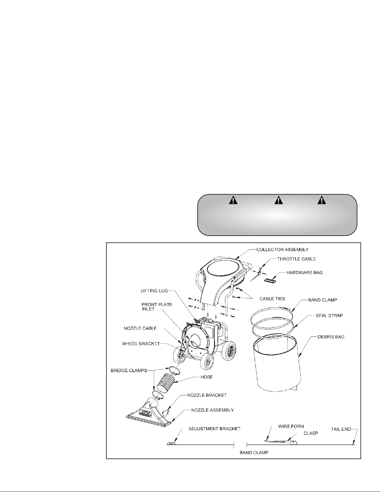
A. Assembly
1. Attach the collector assembly to the base unit:
• Bolt the collector assembly to the frame with 4 sets of
bolts, washer, and nuts
• Slide the rectangular end of the collector over the housing
and mount the flange with 2 sets of washers and nuts
2. Attach the throttle control cable to the handle on the
collector assembly:
• Bolt throttle control lever to handle with washer and nut
• Secure throttle cable to handle with cable ties in 2 places
3. Install the band clamp into the debris bag (wear gloves
when handling band clamp):
• Slide the bracket end of the band clamp through the left
side opening of the sleeve on the debris bag until it
emerges from the right side
• Feed the tail end of the band (on the clasp side) behind
the bracket in the sleeve
• Pinch the wire form on the clasp together and connect it
through 2 holes in the adjustment bracket such that it will
close tightly over the collector
4. Connect the debris bag by placing it over the bottom lip of
the collector and closing the clasp to secure the bag. Adjust
the clasp wire form to the appropriate hole position on the
bracket to insure a tight fit. If the bag will not fit tight within
the range of the 3 adjustment holes, insert the bag seal strap:
• Unhook the wire form from the bracket
• Pull the tail end of the
band back out from
behind the bracket
• Feed one end of the seal
strap behind the metal
band and through the
channel to the other side
• Tuck the other end of
the seal strap behind
the bracket
(overlapping the lead
end of the seal strap)
• Feed the tail end of the
band clamp behind the
bracket (overlap the
seal strap)
• Connect the wire form
to the appropriate holes
in the bracket and
secure the debris bag to
the collector
5. Attach nozzle assembly to
base unit:
• Attach one end of the
hose to the nozzle
assembly with the
bridge clamp
• Slide the other end of
Assembly Instructions
the hose over the edge of the inlet on the front plate
• Hook one side of the nozzle bracket over the front axle
• Bend the other end of the nozzle bracket inward to
hook it over the axle and engage the pins on the wheel
bracket with the slots on the nozzle bracket
• Secure the hose to front plate inlet with the bridge
clamp
• Attach the nozzle cable end fitting through the hole in
the nozzle bracket
6. To remove nozzle assembly (for purposes of storage, or
clearing blockages):
• Turn engine off and disconnect spark plug
• Loosen hose clamp on the front plate with flathead
screwdriver or 5/16 wrench
• Slide hose off of front plate inlet
• Bend one side of nozzle bracket inward and twist the
assembly to remove the hook from the axle
• Twist back and lift to remove the other side of nozzle
bracket from the axle
WARNING DANGER
NEVER RUN OR OPERATE YOUR MACHINE
UNLESS DISCHARGE BAG IS ATTACHED,
AND THE INTAKE NOZZLE IS INSTALLED.
Page 9
7
C. Empty Debris Bag
1. Turn off engine and let it come to a complete stop before
removing the debris bag.
2. Roll vacuum to the desired unloading location
(compost pile, curb-side, wooded area, tarp, etc.).
3. Open clasp on band clamp to release bag to the ground.
Avoid dragging bag on surface to prolong bag life.
4. Empty contents of debris bag (handle straps are provided
on the under side of the bag for aid in dumping contents).
5. Reconnect bag to collector.
D. Refueling the Engine
1. Stop engine and allow it to cool for a few minutes before
refueling.
Operation
WARNING DANGER
THE OPERATOR OF THIS HIGH PERFORMANCE
VAC IS RESPONSIBLE FOR ACCIDENTS OR
HAZARDS OCCURRING TO HIMSELF, OTHER
PEOPLE OR THEIR PROPERTY.
B. Vacuuming
1. Adjust nozzle to desired height by turning the nozzle
control knob, secure position with wing nut.
2. Vacuum debris from lawn or paved surfaces. Vacuum the
following: leaves, small twigs and sticks, acorns, thistles,
seed pods, grass clippings, straw, wood chips, dry mulch,
litter, small cans & bottles, paper products, styrofoam
products.
3. Avoid the following: excessively wet surfaces and debris,
gravel surfaces, large hard objects, rocks, long fibrous
materials (vines, rope, string etc). Do not force anything
into vacuum.
WARNING DANGER
ENGINE EMITS CARBON MONOXIDE. DO NOT
OPERATE OR REFUEL IN ENCLOSED AREA.
A. Start Engine
1. Open fuel valve.
2. Open choke.
3. Set throttle to run.
4. Pull starter rope 1 – 3 times.
5. Allow engine to turn over.
6. Close choke.
7. Set throttle speed to max - Always operate vacuum
at full throttle.
WARNING DANGER
KEEP RECOIL STARTER SCREEN AND ENTIRE
ENGINE CLEAR OF ALL DEBRIS. DO NOT
OPERATE ENGINE WITH AN ACCUMULATION OF
GRASS, DIRT, LEAVES OR OTHER
COMBUSTIBLE MATERIAL NEAR MUFFLER.
WARNING DANGER
DO NOT OPERATE UNIT IF EXCESSIVE
VIBRATION OCCURS; SHUT ENGINE OFF
IMMEDIATELY! REMOVE SPARK PLUG WIRES
AND CHECK FOR DAMAGED IMPELLER,
LOOSE IMPELLER BOLT, LOOSE IMPELLER KEY,
OR LODGED FOREIGN OBJECTS.
B. Put Oil and Gasoline in Engine
Before Starting
1. Little Wonder recommends using SAE 30 Oil. The use of
multi-viscosity oil will result in high oil consumption and
possible engine damage.
2. Add gasoline to the fuel tank, and you are ready to start.
3. See Engine Operating & Maintenance instructions for
more detail description of type and amount of oil and
gasoline used.
C. Use of Lifting Lug
Little Wonder High Performance Vac is supplied with convenient
Lifting Lug that can be used when you need to move the unit.
This Lug can hold weight up to a total of 250 lbs.
WARNING DANGER
HANDLE FUEL WITH CARE. IT IS HIGHLY
FLAMMABLE. FUELING A HOT ENGINE OR NEAR
AN IGNITION SOURCE CAN CAUSE A FIRE AND
RESULT IN SERIOUS PERSONAL INJURY AND/ OR
PROPERTY DAMAGE.
WARNING DANGER
DO NOT USE OR SERVICE THE UNIT WHEN IT’S
SUSPENDED FROM THE LIFTING LUG.
WARNING DANGER
FUEL IS EXTREMELY FLAMMABLE. HANDLE IT
WITH CARE. KEEP AWAY FROM IGNITION
SOURCES. DO NOT SMOKE WHILE FUELING
YOUR EQUIPMENT.
Page 10

8
A. Storage
1. After each use, run HPV with the empty bag attached to help clear out any loose material in the housing.
2. When not in use store High Performance Vac in sheltered area (a dry place) not accessible to children. Keep throttle in the
“Stop” position.
3. The High Performance Vac, as well as fuel, should not be stored in a house or poorly ventilated areas.
4. Do not store fuel in the engine’s gas tank longer then
30 days.
Storage and Maintenance
After First
8 Hrs of Use
✔
Every
Use
✔
✔
✔
✔
Every
5 Hrs
✔
✔
Every
25 Hours
✔
Every
50 Hours
✔
✔
B. Maintenance
Area
*Engine
Check muffler area for
accumulation of debris
Check for excessive vibration
Inspect for loose or damaged parts
Inspect for clean intake nozzle
Inspect labels condition
Check oil level
**Oil change
Service air cleaner
Clean and inspect spark plus
arrester
See Engine Manual
* See Engine Operating & Maintenance instructions for more detail maintenance and service schedule
** Change oil every 25 Hrs if operating under heavy load or high ambient temperature
Page 11
9
D. Directions for removing the Fan
and reinstallation
1. Remove spark plug wire from spark plug.
2. Remove nozzle assembly.
3 Remove front plate assembly.
4. Remove the bolt that secures the fan to the engine
crankshaft.
5. The fan has a 3/4-16 nut welded on the fan hub. Insert a
3/4-16 x 5" long grade 5 (or better) bolt and jack or push
the fan off the engine. (Little Wonder P/N 910505 pressure
screw is recommended.)
6. Replace damaged or worn fan with a new one. If during
fan removal the key (#915) was removed from the keyway,
reinstall it by applying a few drops of the Loctite 380
instant adhesive (“Black Max” P/N 38050) on the key, and
load the key in the keyway of the shaft. (Cure time is
approx. 1 min.)
7. Use a new bolt (#600524) (add Loctite 242 to new bolt)
and washer (#910527) and complete fan installation.
Insure a secure fit upon re-assembling. Torque bolt to
39-51 Ft. lbs.
WARNING DANGER
TURN OFF ENGINE BEFORE YOU DISCONNECT
HOSE, AND MAKE SURE ALL MOVING PARTS
COME TO A COMPLETE STOP.
WARNING DANGER
BE SURE THROTTLE IS IN “STOP” POSITION, AND
FAN HAS COME TO A COMPLETE STOP.
WARNING DANGER
DISCONNECT THE SPARK PLUG WIRES BEFORE
ANY CLEANING OR MAINTENANCE!
WARNING DANGER
WEAR GLOVES, THE CLOG MAY CONTAIN
SHARP MATERIALS.
C. Removing Blockage in Moving Parts
1. Support the housing with 2x4 lumber such that front wheel
are 1” above the ground.
2. Chock the rear wheels with blocks.
3. Remove the nozzle assembly from the front plate.
(See Assembly Instruction 6.)
4. Remove the front wheel assembly.
5. Remove the front plate.
6. Wear gloves and clear out debris from around the impeller
and housing.
Page 12
10
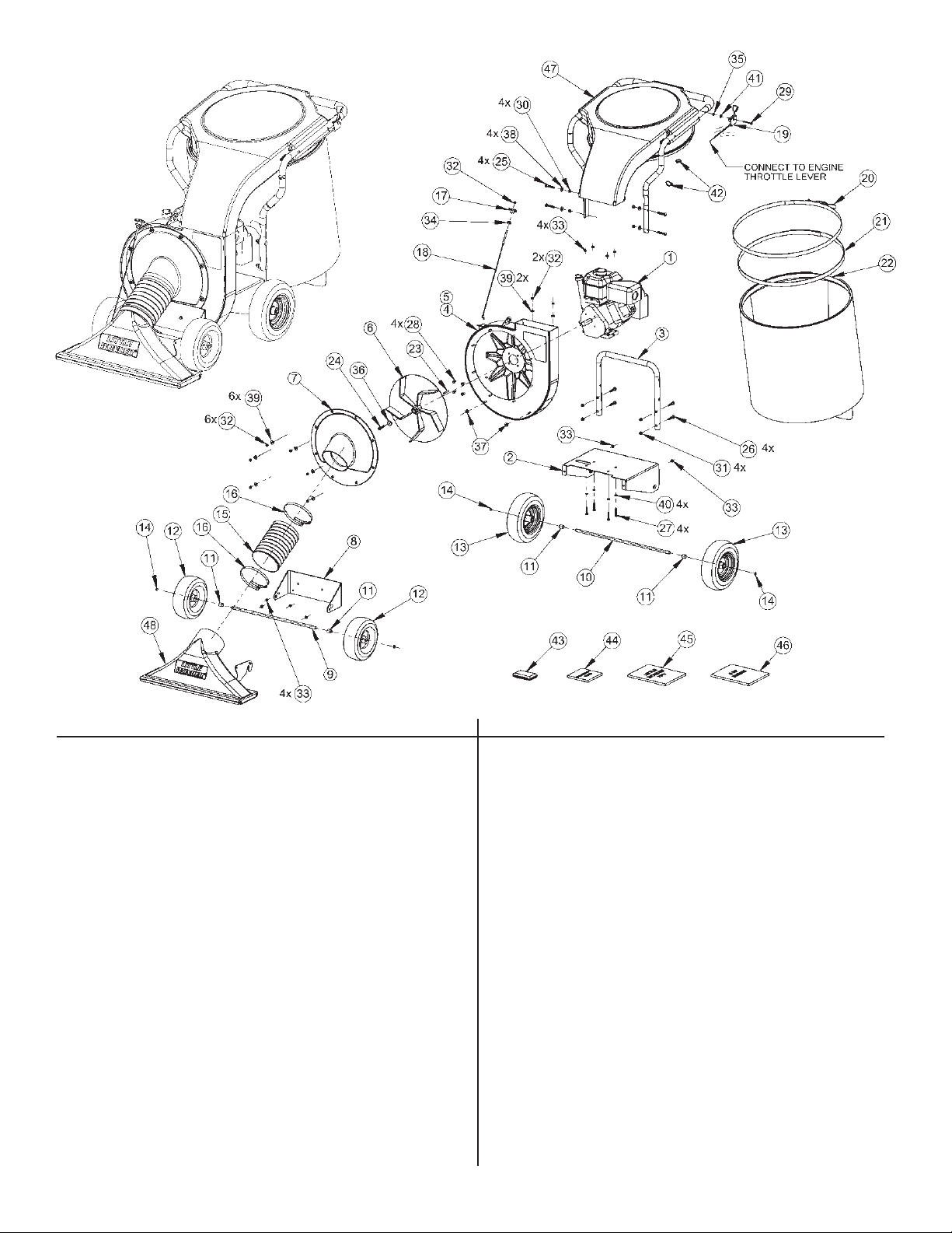
KEY NO.PART NO.DESCRIPTION QTY.
1 910914 ENGINE, 6 HP INTEK 1
2 600180 DECK, HPV, 6 HP 1
3 600184 HANDLE MOUNT 1
4 600186 HOUSING - WITH OUT LINER HOLES 1
5 600187 HOUSING - WITH LINER HOLES 1
6 600114 IMPELLER-BALANCED 1
7 600198 FRONT PLATE, VER. 2 1
8 600182 BRACKET, FRONT WHEELS 1
9 600188 AXLE, FRONT 1
10 600192 AXLE, REAR 1
11 600137 SPACER, WHEEL 4
12 934 WHEEL, 10" 2
13 920300 WHEEL, 12" 2
14 312 SNAP RING, 5/8" D 4
15 600102 HOSE, NOZZLE, 7" D x 10" LG 1
16 720420 BRIDGE CLAMP, HOSE, 7" D 2
17 600162 KNOB, 5/16-18, FEMALE 1
18 600104 CABLE, NOZZLE CONTROL 1
19 600103 THROTTLE CABLE CONTROL 1
20 600176 BAND CLAMP 1
21 600196 BAG SEAL STRAP 1
22 600177 DEBRIS BAG 1
23 915 KEY, 1/4" SQ x 2" LG 1
24 600524 BOLT, 3/8-24 x 1.75" LG 1
25 600504 BOLT, CARRIAGE, 3/8-16 x 2-1/4 4
K
EY NO.PART NO.DESCRIPTION QTY.
26 600525 BOLT, CARRIAGE, 3/8-16 x 2" LG 4
27 942 BOLT, HEX, 5/16-18 x 1-3/4" LG 4
28 910503 BOLT, SERRATED FLANGE,
5/16-24 x 3/4" LG 4
29 600505 BOLT, HEX, 1/4-20 x 2-1/4 1
30 720518 NUT, NYLOCK, 3/8-16 4
31 720594 NUT, SERRATED FLANGE, 3/8-16 4
32 114C NUT, NYLOCK, 5/16-18 9
33 114B NUT, SERRATED FLANGE, 5/16-18 10
34 600507 NUT, WING, 5/16-18 1
35 600506 NUT, NYLOCK, 1/4-20 1
36 910527 WASHER, FAN, FLANGED 1
37 600523 WASHER, 5/16 ID x 3/16 TH 2
38 720516 WASHER, FLAT, 3/8, USS 4
39 720511 WASHER, FLAT, 5/16, USS 8
40 129D WASHER, SPLIT LOCK, 5/16 4
41 720510 WASHER, FLAT, 1/4, USS 1
42 720411 CABLE TIE, 7.5" 2
43 600500 HARDWARE BAG 1
44 16-102 WARRANTY CARD 1
45 600708 OWNERS MANUAL 1
46 N/A ENGINE MANUAL 1
47 SEE DETAIL COLLECTOR ASSEMBLY 1
48 SEE DETAIL NOZZLE ASSEMBLY 1
HPV Parts Assembly
Page 13
11
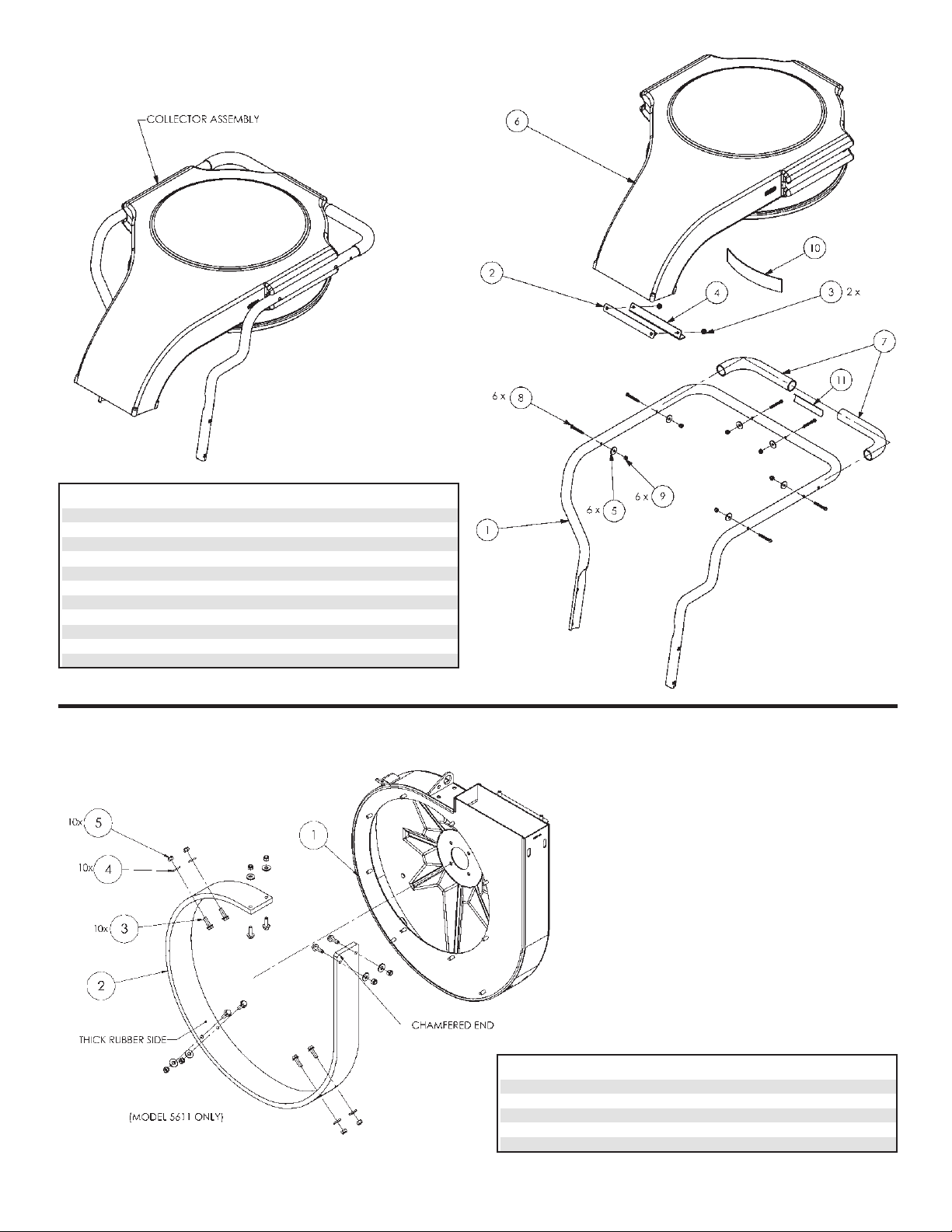
KEY NO. PART NO. DESCRIPTION QTY.
1 600130 HANDLE 1
2 600142 FLANGE CLAMP PLATE 1
3 114B NUT, SERRATED FLANGE, 5/16-18 2
4 600138 FLANGE ANGLE, COLLECTOR 1
5 600518 WASHER, 1/4", COLLECTOR 6
6 600101 DISCHARGE COLLECTOR 1
7 600153 GRIP 2
8 600509 BOLT, BUTTON SHCS, 1/4-20 X 2" LG 6
9 600506 NUT, NYLOCK, 1/4-20 6
10 600161 HOOK STRIP 1
11 600605 WARNING LABEL, DEBRIS BAG 1
HPV Collector Assembly
KEY NO. PART NO. DESCRIPTION QTY.
1 600187 HOUSING ASSEMBLY, WITH LINER HOLES 1
2 600175 LINER 1
3 720592 FLANGE BOLT, 5/16-18 X 1" LG 10
4 720511 WASHER, FLAT, 5/16, USS 10
5 114C NUTS, NYLOCK, 5/16-18 10
HPV Liner Assembly
Page 14
12
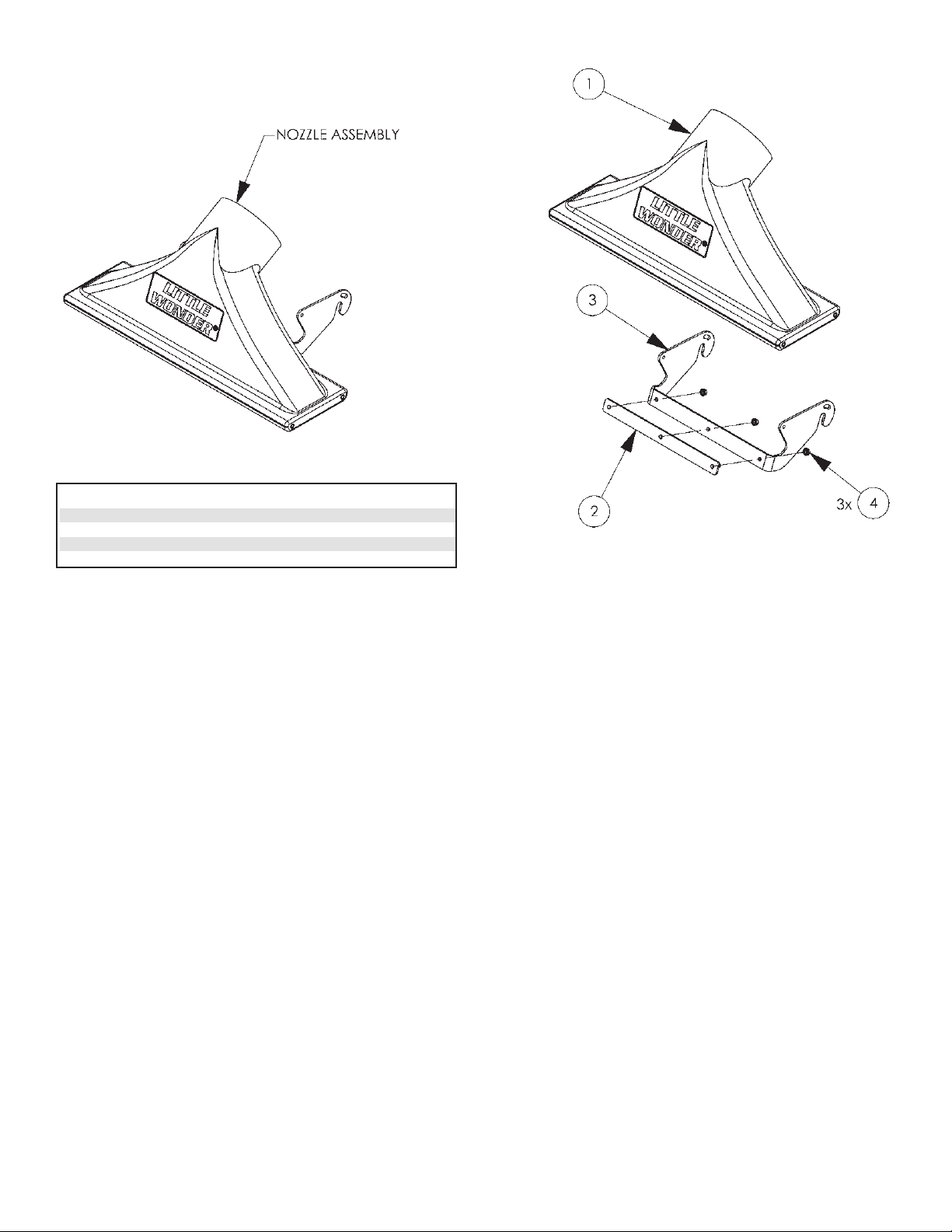
KEY NO. PART NO. DESCRIPTION QTY.
1 600100 NOZZLE 1
2 600133 NOZZLE CLAMP PLATE ASSEMBLY 1
3 600183 NOZZLE BRACKET, VER. 2" 1
4 114B NUT, SERRATED FLANGE, 5/16-18 3
HPV Nozzle Assembly
Page 15

LITTLE WONDER
®
DIVISION OF SCHILLER-PFEIFFER, INCORPORATED
1028 STREET ROAD, P.O. BOX 38
SOUTHAMPTON, PA 18966
PHONE 877-596-6337 • FAX 215-357-8045
www.littlewonder.com
Specifications, descriptions, and illustrative material in this literature are as accurate as known at the time of publication, but are subject to change without notice.
1 YEAR LIMITED SERVICE & WARRANTY POLICY
FOR HIGH PERFORMANCE VAC
The
Little Wonder
High Performance Vac is guaranteed against defects in material
and workmanship for a period of ONE YEAR from date of purchase, when used for
RESIDENTIAL SERVICE, or COMMERCIAL SERVICE. Any
Little Wonder
High
Performance Vac or part found to be defective within the warranty period is to be returned
to any registered Little Wonder Dealer.
Engines for all gasoline powered products are warranted separately by the engine
manufacture for a period of one year. Therefore, there are no warranties made, expressed or
implied, for engines of gasoline powered products by
Little Wonder
.
Transportation charges for parts and units submitted for replacement under this warranty
must be borne by the purchaser.
THIS WARRANTY shall not be effective if the product has been subject to misuse,
negligence or accident, or if the product has been repaired or altered outside of our
Southampton factory in any respect which affects its condition or operation.
Little Wonder
shall not be liable for any special indirect or consequential damages
arising from defective equipment. Any implied warranty, including merchantability of
fitness for a particular purpose, shall not extend beyond the written warranty period.
THIS WARRANTY shall only be effective if the enclosed Warranty/Registration card is
properly filled out and returned to
Little Wonder
, Div. of Schiller-Pfeiffer, Inc. at time
of purchase.
877-LWONDER
WARNING DANGER
THE ENGINE EXHAUST FROM THIS PRODUCT
CONTAINS CHEMICALS KNOWN TO THE STATE OF
CALIFORNIA TO CAUSE CANCER, BIRTH DEFECTS
OR OTHER REPRODUCTIVE HARM.
Page 16

Page 17

1
Table des matières Informations importantes
A. Introduction
De la part de tout le personnel de
Little Wonder
, nous
tenons à vous remercier de votre achat d’un aspirateur haute
performance
Little Wonder
. Cet appareil de ramassage
des déchets a été conçu suivant les normes les plus strictes afin
de vous assurer de nombreuses heures d’utilisation sans
incident.
Ce manuel contient les informations nécessaires à une
utilisation et un entretien sûrs et efficaces. Pour votre sécurité,
il est extrêmement important que vous lisiez et compreniez le
manuel dans son intégralité avant d’utiliser l’appareil.
Caractéristiques techniques :
Modèle Poids à sec Rotation maxi.
5601 182 lbs. (82,500 kg) 3400
5611 184 lbs. (83,400 kg) 3400
B. Informations sur l’entretien
Aspirateur haute performance
Faire appel au revendeur local
Little Wonder
.
Moteur
sous les rubriques « Fournitures de matériel de pelouses et
jardins », « Entretien des pelouses » ou « Tondeuses à
gazon ». Le revendeur aura besoin de connaître le modèle et le
numéro de série de votre moteur. Pour leur emplacement,
veuillez consulter le manuel d’utilisation fourni avec votre
moteur. Faire appel à un revendeur agréé Briggs & Stratton.
Vous trouverez une liste des revendeurs dans les Pages jaunes,
C. Informations particulières sur la sécurité
AVERTISSEMENT DANGER
ATTENTION : CE SYMBOLE ATTIRE VOTRE ATTENTION
SUR D’IMPORTANTES CONSIGNES DE SÉCURITÉ.
LORSQUE VOUS VOYEZ CE SYMBOLE,
TENEZ COMPTE DE L’AVERTISSEMENT ! SOYEZ
VIGILANT !
AVERTISSEMENT DANGER
POUR RÉDUIRE LES RISQUES D’ACCIDENTS,
RESPECTER LES CONSIGNES DE SÉCURITÉ
FIGURANT DANS CE MANUEL. LE NON-RESPECT DE
CES CONSIGNES PEUT ENTRAÎNER DES DOMMAGES
CORPORELS ET MATÉRIELS GRAVES.
AVERTISSEMENT DANGER
L’ÉCHAPPEMENT DU MOTEUR DE CE PRODUIT
CONTIENT DES PRODUITS CHIMIQUES DÉCLARÉS
PAR L’ÉTAT DE LA CALIFORNIE RESPONSABLES DE
CANCER, MALFORMATIONS CONGÉNITALES OU
AUTRES ANOMALIES DE LA REPRODUCTION.
Informations importantes
Introduction . . . . . . . . . . . . . . . . . . . . . . . . . . . .1
Informations sur l’entretien . . . . . . . . . . . . . . .1
Informations particulières sur la sécurité . . . . .1
Déballage
Informations sur le déballage . . . . . . . . . . . . . .2
Sécurité et avertissements
Décalcomanies de sécurité . . . . . . . . . . . . . .2-3
Consignes générales de sécurité
Avertissements – Ce qu’il ne faut pas faire . . .4
Avertissements – Ce qu’il faut faire . . . . . . .4-5
Avertissements concernant le moteur et le
carburant – Ce qu’il ne faut pas faire . . . . . . . .5
Avertissements concernant le moteur et le
carburant – Ce qu’il faut faire . . . . . . . . . . . . . .5
Consignes d’assemblage
Assemblage . . . . . . . . . . . . . . . . . . . . . . . . . . . .6
Plein d’huile et d’essence avant le démarrage .7
Utilisation de l’oreille de levage . . . . . . . . . . . .7
Consignes d’utilisation
Démarrage du moteur . . . . . . . . . . . . . . . . . . . .7
Passage de l’aspirateur . . . . . . . . . . . . . . . . . . .7
Vidage de sac à déchets . . . . . . . . . . . . . . . . . .7
Remplissage du réservoir de carburant . . . . . . .7
Rangement et entretien
Rangement . . . . . . . . . . . . . . . . . . . . . . . . . . . .8
Entretien . . . . . . . . . . . . . . . . . . . . . . . . . . . . . .8
Élimination des blocages dans les pièces
mobiles . . . . . . . . . . . . . . . . . . . . . . . . . . . . . . .9
Démontage du ventilateur . . . . . . . . . . . . . . . . .9
Nomenclature des pièces
Nomenclature des assemblages . . . . . . . . . . .10
Nomenclature des sous-ensembles HPV . . . .11
Garanties
Garantie . . . . . . . . . . . . . . . . .Couverture arrière
Page 18

2
Déballage
1. Enlever le collecteur, la tête d’aspiration et le sac à déchets
de la partie supérieure de l’emballage.
2. Enlever le séparateur en carton.
3. Découper et replier vers le bas la paroi latérale courte de la
boîte.
4. Faire rouler la base de l’aspirateur hors de la boîte.
N° de référence 600602
Décalcomanie
d’avertissement
N° de référence 600605
Décalcomanie d’avertissement
Attention :
Projection
d’objets.
Garder les
spectateurs à
l'écart.
Toujours
porter des
éléments de
protection de
la vision, de
l’ouïe et de la
respiration.
Avant d'effectuer
quelque
intervention de
service ou
d'entretien que ce
soit, débrancher le
fil de bougie.
S'assurer que
l'accélérateur est à
la position d'arrêt.
Il importe de lire
et de
comprendre le
manuel
d’utilisation.
Garder le
manuel
d’utilisation en
lieu sûr.
Garder les
mains et les
pieds à l'écart
des décharges
d’air. Le
ventilateur
rotatif cause des
blessures graves.
Sécurité et avertissements
A. Décalcomanies de sécurité
Les décalcomanies d'avertissement et d'information qu'on
trouve sur différentes parties de cet aspirateur constituent une
partie importante du système de sécurité.
Ces décalcomanies (ou étiquettes) doivent être remplacées si
elles deviennent illisibles par suite d’abrasion ou pour toute
autre raison.
Vous devez les remplacer lorsqu’elles deviennent difficiles à
lire. Leur emplacement et leur numéro de référence pour la
commande sont indiqués à la page 3.
AVERTISSEMENT DANGER
POUR ÉCARTER LES RISQUES DE BLESSURE GRAVE,
UTILISER ET ENTRETENIR CET ASPIRATEUR DE FAÇON
APPROPRIÉE ET PORTER UNE PROTECTION ADAPTÉE.
LIRE ET COMPRENDRE LES CONSIGNES DE SÉCURITÉ ET
TOUTES LES INSTRUCTIONS CONTENUES DANS CE
MANUEL.
PORTER DES ÉLÉMENTS DE PROTECTION DE L’OUÏE, DE
LA VISION ET DE LA RESPIRATION.
N° de référence
600604
NE PAS FAIRE FONCTIONNER L’APPAREIL
LORSQUE SON SAC N’EST PAS EN
PLACE.
ARRÊTER LE MOTEUR ET LE LAISSER S’IMMOBILISER
COMPLÈTEMENT AVANT DE RETIRER LE SAC.
ASPIRATEUR HAUTE PERFORMANCE
LA ROTATION DES LAMES PEUT
PROVOQUER DES BLESSURES
GRAVES. MAINTENIR TOUTES LES
PARTIES DU CORPS À L’ÉCART.
EMPÊCHER LES OBJETS GROS OU
DURS D’ENTRER DANS L’APPAREIL.
À UTILISER POUR LE RAMASSAGE DE
L’HERBE, DES FEUILLES ET DES
DÉCHETS.
NE PAS UTILISER L’APPAREIL
SANS SA TÊTE D’ASPIRATION
ET DISPOSITIF DE MISE EN SAC
OU SANS SON TUYAU
D’ASPIRATION ET TUYAU DE
REFOULEMENT.
Page 19

3
N° de référence
600604
Sécurité et avertissements
N° de référence
600602
Décalcomanie
d’avertissement
N° de référence 600605
Décalcomanie d’avertissement
ASPIRATEUR HAUTE PERFORMANCE
Page 20

4
Consignes générales de sécurité
1. Prendre le temps de lire et de comprendre ce manuel.
2. Porter des éléments. de protection de la vision, de l’ouïe et
de la respiration, ainsi que des chaussures et vêtements
adaptés
3. Pendant le fonctionnement de l’appareil, veiller à toujours
se trouver dans une position sure en conservant à tout
moment une posture ferme et un bon équilibre.
4. Éviter de travailler en présence d’enfants, d’animaux
domestiques et de curieux.
5. Ne jamais tenter d’utiliser un appareil qui est incomplet ou
qui a fait l’objet d’une modification non autorisée.
6. Éviter le contact et l’inhalation des liquides, brouillards,
poussières et gaz dangereux.
7. Ne pas autoriser les enfants à utiliser l’appareil.
8. Ne pas contourner ni enlever les dispositifs de sécurité.
12. Maintenir les mains à l’écart de l’orifice d’entrée du tuyau
et de la goulotte d’éjection.
13. Débrancher la bougie avant tout nettoyage ou entretien.
14. Porter dans gants pour la protection des mains.
15. Être conscient du fait que l’appareil est bruyant et peut
empêcher la communication de la parole pendant son
fonctionnement normal.
A. Avertissements – Ce qu’il ne faut pas faire
Ne pas essayer d’enlever des matières prises dans le collecteur
ou l’éjecteur lorsque l’appareil est en fonctionnement ou
lorsque le ventilateur tourne.
Ne pas installer de constituants, ni en enlever, pendant le
fonctionnement de l’appareil. Ne pas oublier d’arrêter le
moteur avant tout changement de configuration. S'assurer que
l'accélérateur est en position d'arrêt et que l’appareil est
complètement arrêté. Débrancher le fil de bougie avant
d’enlever toute matière.
Ne pas essayer de réparer cet appareil. Confier les réparations
à un revendeur Little Wonder ou technicien qualifié. S'assurer
que seules des pièces de rechange Little Wonder et des pièces
de rechange recommandées par le constructeur du moteur sont
utilisées.
Ne pas laisser le moteur en marche pendant que l’appareil est
sans surveillance.
Ne pas stocker, renverser ni utiliser d’essence à proximité
d’une flamme ou d’une source d’étincelles.
B. Avertissements – Ce qu’il faut faire
S’habiller adéquatement. Ne pas porter de vêtements flottants
ni de bijoux. Ils peuvent être happés par les pièces en
mouvement. L'utilisation de gants robustes, de chaussures
antidérapantes et de lunettes de sécurité est recommandée.
Toujours porter des protecteurs auditifs lorsque cela est
possible. Utiliser un filtre facial pour ne pas respirer la
poussière.
Rester toujours vigilant. Faire attention à ce que l’on fait et
faire preuve de discernement. Ne pas utiliser l’appareil
lorsqu’on est fatigué.
Maintenir en toutes circonstances les mains à l’écart de la prise
d’air et de la goulotte d’éjection. Maintenir les deux mains sur
le guidon lorsque l’appareil est en marche.
Entretenir et examiner systématiquement l’appareil avec
beaucoup de soin. Suivre les instructions d’entretien données
dans le manuel.
AVERTISSEMENT DANGER
9. LE VENTILATEUR CONTINUE À TOURNER PENDANT
UN MOMENT APRÈS L’ARRÊT DU MOTEUR.
AVERTISSEMENT DANGER
NE PAS FUMER PENDANT LE REMPLISSAGE DU
RÉSERVOIR DE CARBURANT.
AVERTISSEMENT DANGER
10. VENTILATEUR TOURNANT. NE PAS ESSAYER
D’ENLEVER DES MATIÈRES PRISES DANS LE
COLLECTEUR OU L’ÉCHAPPEMENT LORSQUE
L’APPAREIL EST EN FONCTIONNEMENT OU
LORSQUE LE VENTILATEUR TOURNE.
AVERTISSEMENT DANGER
NE PAS UTILISER L’APPAREIL SI LE SILENCIEUX EST
ENDOMMAGÉ OU ABSENT.
AVERTISSEMENT DANGER
11. NE PAS FAIRE FONCTIONNER L’APPAREIL S’IL
VIBRE DE MANIÈRE EXCESSIVE ; ARRÊTER
IMMÉDIATEMENT LE MOTEUR ! DÉBRANCHER LE FIL
DE BOUGIE ET DÉTERMINER SI LE ROTOR EST
ENDOMMAGÉ, SI UN DE SES BOULONS EST
DESSERRÉ, SI SA CLAVETTE EST LÂCHE OU SI UN
CORPS ÉTRANGER S’EST LOGÉ DANS L’APPAREIL.
Page 21

5
AVERTISSEMENT DANGER
SI L’APPAREIL EST UTILISÉ DE MANIÈRE
INAPPROPRIÉE OU SI LES CONSIGNES DE
SÉCURITÉ NE SONT PAS SUIVIES, L’UTILISATEUR
S’EXPOSE ET EXPOSE LES AUTRES À UN RISQUE
DE BLESSURE GRAVE.
PRENDRE LE TEMPS DE LIRE ET DE COMPRENDRE
CE QUI SUIT AVANT DE FAIRE FONCTIONNER CET
APPAREIL.
AVERTISSEMENT DANGER
MANIPULER LE CARBURANT AVEC PRÉCAUTION.
IL EST TRÈS INFLAMMABLE. POUR ÉCARTER LES
RISQUES D’INCENDIE ET DE DOMMAGES
CORPORELS ET MATÉRIELS GRAVES, NE PAS
REMPLIR LE RÉSERVOIR SI LE MOTEUR EST
CHAUD OU S’IL SE TROUVE À PROXIMITÉ D’UNE
SOURCE D’INFLAMMATION.
D. Avertissements concernant le moteur
et le carburant – Ce qu’il faut faire
Toujours utiliser de l’essence fraîche. L'utilisation
d’essence viciée peut causer des fuites.
Tirer le cordon du démarreur lentement jusqu'à ce
qu'une résistance se fasse sentir. Tirer ensuite le cordon
rapidement pour éviter les rebonds et prévenir des
blessures au bras ou à la main.
L’utilisation de silencieux à pare-étincelles est requise
par la loi de l’État de la Californie (article 4442 du
Code des ressources publiques de la Californie), ainsi
que dans d’autres États et municipalités. La loi fédérale
américaine s’applique sur les territoires fédéraux
américains.
Manipuler le carburant avec précaution ; il est très
inflammable. Ne jamais ajouter de carburant dans le
réservoir d’une machine dont le moteur est chaud ou en
marche. Ne pas inhaler les vapeurs de carburant, car
elles sont toxiques.
Le système d’allumage par étincelle satisfait toutes
les exigences des règlements canadiens sur le
matériel causant des interférences.
il émet du monoxyde de carbone et autres gaz toxiques.
Ne pas faire fonctionner le moteur si le système
d’allumage provoque des étincelles à l'extérieur du
cylindre. Durant les vérifications périodiques de la
bougie, maintenir la bougie à une distance suffisante du
cylindre pour éviter d’enflammer le carburant
s’évaporant du cylindre.
Ne pas vérifier la production d’étincelles avec la bougie
ou le fil de bougie enlevé et mis à la terre. Utiliser un
dispositif d’essai homologué. Les étincelles peuvent
enflammer les vapeurs d’essence.
Ne pas faire fonctionner le moteur en présence d’une
odeur d'essence ou autre possibilité d’explosion.
Ne pas faire fonctionner la machine en cas de présence
d’un déversement d’essence. Nettoyer complètement
l'essence déversée avant de mettre le moteur en marche.
Ne pas faire le plein de carburant à l'intérieur ou dans
un endroit mal aéré.
Ne pas faire fonctionner l’appareil en cas
d'accumulation de déchets autour du silencieux ou des
ailettes de refroidissement.
Pour éviter les brûlures graves, ne pas toucher les
silencieux, ailettes de refroidissement ou cylindres
chauds.
B. Advertencias – “Hacer siempre” –
continuación
Ranger l’appareil à l’intérieur. Lorsqu’il n’est pas utilisé,
conserver l’appareil dans un endroit abrité (au sec) où il n’est
pas accessible aux enfants. L’appareil et le carburant ne
doivent pas être rangés à l'intérieur d’une habitation. Garder
l'accélérateur en position d'arrêt.
Vérifier toujours que l’appareil est complètement assemblé. Ne
jamais le faire fonctionner si les protections et les déflecteurs
ne sont pas en place. S'assurer que tous les écrous, boulons et
vis sont à leur place et bien serrés.
Garder toujours l'accélérateur en position d'arrêt lorsque
l’appareil n'est pas en usage.
Garder une distance sûre entre plusieurs opérateurs qui
travaillent ensemble.
C. Avertissements concernant le moteur
et le carburant – Ce qu’il ne faut pas faire
Ne pas faire le plein de carburant ni en vérifier le
niveau lorsque l’on fume ou qu’on se trouve à proximité
d’une flamme nue ou autre source d’inflammation.
Arrêter le moteur et s’assurer qu’il est froid avant de
refaire le plein.
Ne pas laisser le moteur en marche pendant que
l’appareil est sans surveillance. Arrêter le moteur avant
de transporter l’appareil d’un endroit à un autre.
Ne pas mettre cet appareil en marche ni le faire
fonctionner à l’intérieur ou dans un endroit mal aéré car
Page 22

6
Consignes d’assemblage
AVERTISSEMENT DANGER
NE JAMAIS FAIRE FONCTIONNER L’APPAREIL SI LE
SAC À DÉCHETS N’EST PAS EN PLACE OU SI LA
TÊTE D’ASPIRATION N’EST PAS INSTALLÉE.
A. Assemblage
1. Fixer le collecteur sur la base :
• Boulonner le collecteur sur le châssis à l’aide des 4 jeux
de boulons munis de leur rondelle et de leur écrou.
• Faire glisser l’extrémité rectangulaire du collecteur sur le
châssis et en fixer la bride à l'aide des 2 rondelles et des 2
écrous fournis.
2. Fixer le câble de commande de l’accélérateur sur le guidon
du collecteur :
• Monter le levier de commande de l’accélérateur sur le
guidon à l’aide du boulon, de la rondelle et de l’écrou
fournis.
• À l’aide de deux attaches, fixer le câble de l’accélérateur
sur le guidon.
3. Installer le collier de serrage dans le sac à déchets (manipuler
le collier de serrage en se protégeant les mains avec des
gants) :
• Introduire l’extrémité du collier de serrage comportant la
pièce d’attache à trois trous dans l’ouverture gauche du
manchon du sac à déchets et faire coulisser le collier
jusqu’à ce que l’extrémité ressorte par l’ouverture droite.
• Alimenter l’extrémité de queue du collier (du côté du
fermoir) derrière la pièce d’attache dans le manchon.
• Rapprocher les broches du dispositif de verrouillage en
les pinçant et les brancher sur deux de la pièce d’attache
de manière à obtenir un serrage ferme sur le collecteur.
4. Fixer le sac à déchets en le plaçant sur la lèvre inférieure du
collecteur et en refermant le fermoir. Placer les broches dans
les trous appropriés de la pièce d’attache de manière à
obtenir un bon serrage. S’il est impossible d’obtenir un bon
serrage avec les trois trous disponibles, insérer la bande de
scellement :
• Décrocher les broches de la pièce d’attache.
• Sortir l’extrémité de queue du collier de serrage de
derrière la pièce
d’attache.
• Insérer une des
extrémités de la bande
de scellement derrière
le collier métallique et
dans le manchon
jusqu’à ce qu’elle
ressorte de l’autre côté
du manchon.
• Placer l’autre extrémité
de la bande de
scellement derrière la
pièce d’attache (par
chevauchement de
l’extrémité avant de la
bande de scellement).
• Insérer l’extrémité de
queue du collier de
serrage derrière la pièce
d’attache (par
chevauchement de la
bande de scellement).
• Brancher les broches
dans les trous
appropriés de la pièce
d’attache de manière à
fixer solidement le sac
à déchets sur le
collecteur.
5. Fixer la tête d’aspiration
sur la base :
• À l’aide d’un collier de
raccordement, fixer une
des extrémités du tuyau
sur la tête d’aspiration.
• Faire coulisser l’autre extrémité du tuyau sur le rebord
de l’alimentation sur le capot avant.
• Accrocher une des extrémités du support de la tête
d’aspiration sur l’essieu avant.
• Courber l’autre extrémité du support de la tête vers
l’intérieur jusqu’à ce qu’il s’accroche sur l’essieu et
engager les goupilles de support de roues dans les
logements du support de la tête.
• À l’aide d’un collier de raccordement, fixer le tuyau
sur l’admission du capot avant.
• Fixer le raccord de l’extrémité du câble de la tête
d’aspiration par le trou du support de la tête.
6. Dépose de la tête d’aspiration (pour le rangement ou le
nettoyage des blocages) :
• Arrêter le moteur et débrancher le fil de la bougie.
• À l’aide d’un tournevis plat ou d’une clé 5/16 de po,
desserrer le collier de raccordement du tuyau au capot
avant.
• En le faisant glisser, séparer le tuyau de l’admission
sur le capot avant.
• Courber une des extrémités du support de la tête
d’aspiration vers l’avant et faire pivoter l’ensemble
pour le décrocher de l’essieu.
• Pour décrocher de l’essieu l’autre extrémité du support
de la tête d’aspiration, faire pivoter dans l’autre sens et
soulever.
ENSEMBLE COLLECTEUR
CÂBLE DE L’ACCÉLÉRATEUR
SACHET DE MATÉRIEL
ATTACHES DE
CÂBLE
COLLIER DE
SERRAGE
BANDE DE
SCELLEMENT
SAC À DÉCHETS
DISPOSITIF DE
VERROUILLAGE À BROCHES
EXTRÉMITÉ
DE QUEUE
COLLIER DE SERRAGE
PIÈCE D’ATTACHE
ENSEMBLE TÊTE D’ASPIRATION
SUPPORT DE LA TÊTE D’ASPIRATION
TUYAU
OREILLE DE LEVAGE
ADMISSION SUR LE
CAPOT AVANT
CÂBLE DE LA TÊTE
D’ASPIRATION
SUPPORT DE
ROUES
COLLIERS DE
RACCORDEMEN
T
FERMOIR
Page 23

7
C. Vidage du sac à déchets
1. Arrêter le moteur et le laisser revenir complètement au
repos avant d’enlever le sac à déchets.
2. Faire rouler l’aspirateur jusqu’à l’endroit de décharge
désiré (tas de compost, bord du trottoir, zone boisée,
bâche, etc.)
3. Pour libérer le sac à déchets sur le sol, ouvrir le fermoir du
collier de serrage. Pour ne pas réduire la durée de vie du
sac, éviter de le traîner sur le sol.
4. Vider le contenu du sac à déchets (des sangles-poignées se
trouvent à la partie inférieure du sac pour en faciliter le
vidage).
5. Replacer le sac sur le collecteur.
D. Remplissage du réservoir d’essence
1. Arrêter le moteur et le laisser refroidir quelques minutes
avant de remplir le réservoir d’essence.
Consignes d’utilisation
AVERTISSEMENT DANGER
L’UTILISATEUR DE CET APPAREIL EST
RESPONSABLE DES ACCIDENTS OU DES DANGERS
ENVERS LUI-MÊME, LES AUTRES ET POUR LES
BIENS MATÉRIELS.
B. Passage de l’aspirateur
1. Régler la tête d’aspiration à la hauteur désirée en tournant
le bouton de commande, puis fixer sa position à l’aide de
l’écrou à oreilles.
2. Aspirer les déchets de la pelouse ou de la surface
artificielle. On peut aspirer les matières suivantes :
feuilles, brindilles et rameaux, glands, chardons, gousses,
tontes de gazon, paille, copeaux, paillis sec, litière, petites
canettes et bouteilles, articles en papier et articles en
mousse de polystyrène.
3. Ne pas utiliser en présence des conditions suivantes :
surfaces et déchets trop mouillés, surfaces couverte de
gravier, gros objets durs, pierres, longs objets fibreux
(liane, corde, ficelle, etc.) Ne pas faire entrer un objet de
force dans l’aspirateur.
AVERTISSEMENT DANGER
LE CARBURANT EST EXTRÊMEMENT
INFLAMMABLE. LE MANIPULER AVEC
PRÉCAUTION. LE GARDER À L’ÉCART DE TOUTE
SOURCE D’INFLAMMATION. NE PAS FUMER
DURANT LE REMPLISSAGE DU RÉSERVOIR.
AVERTISSEMENT DANGER
LE MOTEUR ÉMET DU MONOXYDE DE CARBONE. NE PAS
FAIRE FONCTIONNER L’APPAREIL NI REMPLIR SON
RÉSERVOIR D’ESSENCE DANS UN ENDROIT CONFINÉ.
A. Démarrage du moteur
1. Ouvrir le robinet d’arrivée d’essence.
2. Ouvrir le volet de départ.
3. Placer l’accélérateur sur la position de fonctionnement.
4. Tirer sur le cordon du démarreur une à trois fois.
5. Laisser le moteur démarrer.
6. Fermer le volet de départ.
7. Placer l’accélérateur sur la position de puissance
maximale. Toujours faire fonctionner l’aspirateur à plein
régime.
AVERTISSEMENT DANGER
MAINTENIR LA GRILLE DU LANCEUR ET TOUT LE
MOTEUR EXEMPTS DE TOUT DÉCHET. NE PAS
FAIRE FONCTIONNER LE MOTEUR EN PRÉSENCE
D’UNE ACCUMULATION D’HERBE, DE SALETÉ, DE
FEUILLES OU AUTRE MATIÈRE COMBUSTIBLE
PRÈS DU SILENCIEUX.
C. Utilisation de l’oreille de levage
L’aspirateur haute performance Little Wonder est doté d’une
oreille de levage pratique qu’on peut utiliser pour le déplacer.
Cette oreille de levage peut supporter un poids total de 114 kg
(250 lb).
AVERTISSEMENT DANGER
NE PAS FAIRE FONCTIONNER NI ENTRETENIR
L’APPAREIL LORSQU’IL EST SUSPENDU PAR
L’OREILLE DE LEVAGE.
AVERTISSEMENT DANGER
MANIPULER LE CARBURANT AVEC PRÉCAUTION.
IL EST TRÈS INFLAMMABLE. POUR ÉCARTER LES
RISQUES D’INCENDIE ET DE DOMMAGES
CORPORELS ET MATÉRIELS GRAVES, NE PAS
REMPLIR LE RÉSERVOIR SI LE MOTEUR EST
CHAUD OU S’IL SE TROUVE À PROXIMITÉ D’UNE
SOURCE D’INFLAMMATION.
B. Plein d’huile et d’essence avant le
démarrage
1. Little Wonder recommande l’utilisation d’huile SAE 30.
L’utilisation d’huile à viscosité multiple provoquerait une
forte consommation d’huile et endommagerait le moteur.
2. Après remplissage du réservoir d’essence, l’appareil est
prêt à être mis en marche.
3. Consulter les instructions sur le fonctionnement et
l’entretien du moteur pour une description plus détaillée
des types et quantités d’huile et d’essence à utiliser.
AVERTISSEMENT DANGER
NE PAS FAIRE FONCTIONNER L’APPAREIL S’IL
VIBRE DE MANIÈRE EXCESSIVE ; ARRÊTER
IMMÉDIATEMENT LE MOTEUR ! DÉBRANCHER LE
FIL DE BOUGIE ET DÉTERMINER SI LE ROTOR EST
ENDOMMAGÉ, SI UN DE SES BOULONS EST
DESSERRÉ, SI SA CLAVETTE EST LÂCHE OU SI UN
CORPS ÉTRANGER S’EST LOGÉ DANS L’APPAREIL.
Page 24

8
A. Rangement
1. Après chaque utilisation, faire fonctionner l’appareil avec le sac à déchet vide de manière à éjecter toutes les matières éparses qui
pourraient se trouver à l’intérieur.
2. Lorsqu’il n’est pas utilisé, conserver l’appareil dans un endroit abrité (au sec) qui n’est pas accessible aux enfants. Garder
l'accélérateur en position d'arrêt.
3. L’appareil et le carburant ne doivent pas être rangés à l'intérieur d’une habitation ou d’un endroit confiné.
4. Ne pas garder le carburant dans le réservoir de l’appareil pendant plus de 30 jours.
Rangement et entretien
Après les 8 premières
heures d’utilisation
✔
À chaque
utilisation
✔
✔
✔
✔
Toutes les 5
heures
✔
✔
Toutes les
25 heures
✔
Toutes les
50 heures
✔
✔
B. Entretien
Domaine
*Moteur
Vérifier l’absence d’une accumulation de déchets à
proximité du silencieux.
Vérifier que l’appareil ne vibre pas de manière excessive.
Vérifier qu’aucune pièce n’est desserrée ou endommagée.
Vérifier la propreté de la tête d’aspiration.
Vérifier la condition des décalcomanies.
Vérifier le niveau d’huile.
**Changer l’huile.
Nettoyer le filtre à air.
Nettoyer et inspecter le pare-étincelles de la bougie.
Voir le manuel du moteur
* Voir les consignes d’utilisation et d’entretien du moteur pour un programme d’entretien plus détaillé.
** En cas de charges ou températures ambiantes élevées, changer l’huile toutes les 25 heures.
Page 25

9
D. Instructions pour le démontage et remontage
du ventilateur
1. Débrancher le fil de bougie.
2. Enlever la tête d’aspiration.
3 Enlever la plaque frontale.
4. Enlever le boulon retenant le ventilateur sur le vilebrequin
du moteur.
5. Le ventilateur est doté un écrou 3/4-16 soudé sur son
moyeu. Y visser un boulon 3/4–16 d’au moins 12 cm de
long et de qualité au moins égale à classe 5 et séparer le
ventilateur du moteur en le poussant ou par effet de levier
(il est recommandé d’utiliser la vis de pression Little
Wonder node réf. 910505).
6. Remplacer le ventilateur endommagé ou usé par un
nouveau. Si, pendant le démontage du ventilateur, la
clavette (no915) a été extraite du logement de clavette, la
réinstaller en lui appliquant quelques gouttes de l’adhésif à
action instantanée Loc Tite 380 (« Black Max » node réf.
38050) et en la replaçant dans son logement.
(Le temps de prise est d’environ 1 minute.)
7. Utiliser un nouveau boulon (node réf. 600524) (en
l’enduisant de Loctite 242) et une nouvelle rondelle (node
réf. 910527) et terminer l’installation du ventilateur. Veiller
à assurer une bonne fixation pendant le remontage. Serrer
le boulon sous un couple de compris entre 55 N.m et 70
N.m (39 ft. lbs et 51 ft. lbs).
C. Élimination des blocages dans les pièces
mobiles
1. Soutenir l’appareil avec des cales en bois ayant une section
d’au 10 cm sur 5cm, de manière à ce que les roues soient
soulevées de 2 à 3 cm du sol.
2. Bloquer les roues arrière avec des cales.
3. Déposer la tête d’aspiration.
(Voir section 6 des instructions d’assemblage.)
4. Déposer l’ensemble de l’essieu avant.
5. Déposer le capot avant.
6. En portant des gants, nettoyer les débris se trouvant autour
du rotor et dans le carter.
AVERTISSEMENT DANGER
ARRÊTER LE MOTEUR AVANT DE DÉBRANCHER LE
TUYAU ET VÉRIFIER QUE TOUTES LES PIÈCES
MOBILES ONT CESSÉ DE BOUGER..
AVERTISSEMENT DANGER
S'ASSURER QUE L'ACCÉLÉRATEUR EST EN
POSITION D'ARRÊT ET QUE LE VENTILATEUR
S'EST ARRÊTÉ COMPLÈTEMENT.
AVERTISSEMENT DANGER
DÉBRANCHER LE FIL DE BOUGIE AVANT TOUT
NETTOYAGE OU ENTRETIEN.
AVERTISSEMENT DANGER
PORTER DES GANTS, CAR L’OBSTRUCTION PEUT
CONTENIR DES OBJETS COUPANTS.
Page 26

10
REPÈRE N
O
DE RÉF.DESCRIPTION QTÉ.
1 MOTEUR INTEK 6 Ch 1
2 600180 PLATE-FORME HPV 6 Ch 1
3 600184 MONTURE DE GUIDON 1
4 600186 CARTER – SANS TROUS POUR CHEMISE 1
5 600187 CARTER – AVEC TROUS POUR CHEMISE 1
6 600114 ROTOR ÉQUILIBRÉ 1
7 600198 CAPOT AVANT VERTICAL 2 1
8 600182 SUPPORT DES ROUES AVANT 1
9 600188 ESSIEU AVANT 1
10 600192 ESSIEU ARRIÈRE 1
11 600137 ENTRETOISE DE ROUES 4
12 934 ROUE DE 25 cm 2
13 920300 ROUE DE 30 cm 2
14 312 CIRCLIP, DIAM. 5/8 PO 4
15 600102
TUYAU DE LA TÊTE D’ASPIRATION, DIAM. 7 PO, LONG. 10 PO
1
16 720420 BRIDE DE TUYAU, DIAM. 7 PO 2
17 600162
BOUTON DE COMMANDE DE LA TÊTE D’ASPIRATION, FEM. 5/16-18
1
18 600104
CÂBLE DE COMMANDE DE LA TÊTE D’ASPIRATION
1
19 600103
CÂBLE DE COMMANDE DE L’ACCÉLÉRATEUR
1
20 600176 COLLIER DE SERRAGE 1
21 600196
BANDE DE SCELLEMENT DU SAC À DÉCHETS
1
22 600177 SAC À DÉCHETS 1
23 915
CLAVETTE À SECT. CARRÉE 1/4 PO, LONG. 2 PO
1
24 600524 BOULON, 3/8-24, LONG. 1,75 PO 1
25 600504
BOULON DE CARROSSERIE, 3/8-16 x 2 -1/4
4
R
EPÈRE NODE RÉF.DESCRIPTION QTÉ.
26 BOULON DE CARROSSERIE, 3/8-16 x LONG. 2 PO 4
27 942
BOULON HEXAGONAL, 5/16-18 x 1-3/4 PO
4
28 910503
BOULON DE FIXATION À BRIDE CANNELÉE,
5/16-24 x 3/4 PO 4
29 600505 BOULON HEXAGONAL, 1/4-20 x 2-1/4 1
30 720518 ÉCROU NYLOCK, 3/8-16 4
31 720594 ÉCROU À BRIDE CANNELÉE, 3/8-16 4
32 114C ÉCROU NYLOCK, 5/16-18 9
33 114B ÉCROU À BRIDE CANNELÉE, 5/16-18 10
34 600507 ÉCROU À OREILLES, 5/16-18 1
35 600506 ÉCROU NYLOCK, 1/4-20 1
36 910527 RONDELLE DE VENTILATEUR À BRIDE 1
37 600523 RONDELLE, DI 5/16 X FIL. 3/16 2
38 720516 RONDELLE PLATE USS 3/8 4
39 720511 RONDELLE PLATE USS 5/16 8
40 129D
RONDELLE DE BLOCAGE FENDUE, 5/16
4
41 720510 RONDELLE PLATE USS 1/4 1
42 720411 ATTACHE DE CÂBLE, 7,5 PO 2
43 600500 SACHET DE MATÉRIEL 1
44 16-102 FICHE DE GARANTIE 1
45 600708 MANUEL D’UTILISATION 1
46 S.O. MANUEL DU MOTEUR 1
47
VOIR DÉTAIL
ENSEMBLE COLLECTEUR 1
48
VOIR DÉTAIL
ENSEMBLE TÊTE D’ASPIRATION 1
Nomenclature des assemblages
RACCORDER AU LEVIER
DE L’ACCÉLÉRATEUR
Page 27

11
REPÈRE NODE RÉF. DESCRIPTION QTÉ.
1 600130 GUIDON 1
2 600142 PLAQUE D’ASSEMBLAGE DE BRIDE 1
3 114B ÉCROU À BRIDE CANNELÉE, 5/16-18 2
4 600138 CORNIÈRE DU COLLECTEUR 1
5 600518 RONDELLE DU COLLECTEUR, 1/4 PO 6
6 600101 COLLECTEUR D’ÉJECTION 1
7 600153 POIGNÉE 2
8 600509 BOULON SHCS, 1/4-20 X 2 PO 6
9 600506 ÉCROU NYLOCK, 1/4-20 6
10 600161 SUPPORT DE FIXATION 1
11 600605
ÉTIQUETTE D’AVERTISSEMENT DU SAC À DÉCHETS
1
Ensemble collecteur HPV
REPÈRE NODE RÉF. DESCRIPTION QTÉ.
1 600187 CARTER – AVEC TROUS POUR CHEMISE 1
2 600175 CHEMISE 1
3 720592 BOULON DE BRIDE, 5/16-18, LONG. 1 PO 10
4 720511 RONDELLE PLATE USS 5/16 10
5 114C ÉCROU NYLOCK, 5/16-18 10
Chemise HPV
ENSEMBLE COLLECTEUR
EXTRÉMITÉ BISEAUTÉE
(MODÈLE 5611 SEULEMENT)
PAROI EN CAOUTCHOUC ÉPAIS
Page 28

12
REPÈRE NODE RÉF. DESCRIPTION QTÉ.
1 600100 TÊTE D’ASPIRATION 1
2 600133
PLAQUE D’ASSEMBLAGE DE LA TÊTE D’ASPIRATION
1
3 600183 SUPPORT VERTICAL DE LA TÊTE D’ASPIRATION 2"1
4 114B ÉCROU À BRIDE CANNELÉE, 5/16-18 3
Tête d’aspiration HPV
ENSEMBLE TÊTE D’ASPIRATION
Page 29

LITTLE WONDER
®
DIVISION OF SCHILLER-PFEIFFER, INCORPORATED
1028 STREET ROAD, P.O. BOX 38
SOUTHAMPTON, PA 18966
Téléphone 877-596-6337 • Télécopieur 215-357-8045
www.littlewonder.com
Les caractéristiques, descriptions et illustrations de ce guide sont exactes au mieux de notre connaissance au moment de la publication, mais elles sont susceptibles
d’être modifiées sans préavis.
GARANTIE LIMITÉE DE RÉPARATION D’UN AN ET POLITIQUE DE
GARANTIE POUR L’ASPIRATEUR HAUTE PERFORMANCE HPV
L’aspirateur haute performance
Little Wonder
est garanti contre les vices de matériaux
et de main-d’œuvre pendant UN AN à compter de la date d’achat lorsqu’il est utilisé pour
un USAGE RÉSIDENTIEL ou COMMERCIAL. Tout aspirateur haute performance ou
pièce
Little Wonder
s’avérant défectueux(défectueuse) pendant la période de garantie
doit être renvoyé(e) à un revendeur agréé Little Wonder.
Les moteurs de tous les appareils à essence sont garantis séparément par le fabricant du
moteur pendant un an. Par conséquent, aucune garantie, explicite ou implicite, n’est fournie
par
Little Wonder
sur les moteurs des appareils à essence.
Les frais de transport des pièces détachées et des appareils renvoyés en vue de leur
remplacement dans le cadre de cette garantie incombent à l'acheteur.
CETTE GARANTIE sera de nul effet si le produit a fait l'objet d'une utilisation erronée, de
négligence ou d'un accident, ou si le produit a été réparé ou altéré hors de notre usine de
Southampton ou d'un centre de réparation agréé d'une manière qui influe sur son état ou
son fonctionnement.
Little Wonder
décline toute responsabilité en cas de dommages particuliers indirects
ou accessoires liés à la défectuosité du matériel. Aucune garantie implicite, notamment
garantie de qualité marchande ou d'aptitude à une fin particulière, ne s'étend au-delà de la
période de garantie spécifiée ci-dessus.
LA PRÉSENTE GARANTIE n’est valide que si la fiche de garantie et d’enregistrement cijointe a été correctement remplie et renvoyée à
Little Wonder
, division de la société
Schiller-Pfeiffer, Inc., au moment de l’achat.
877-LWONDER
AVERTISSEMENT DANGER
L’ÉCHAPPEMENT DU MOTEUR DE CE PRODUIT
CONTIENT DES PRODUITS CHIMIQUES DÉCLARÉS PAR
L’ÉTAT DE LA CALIFORNIE RESPONSABLES DE
CANCER, MALFORMATIONS CONGÉNITALES OU
AUTRES ANOMALIES DE LA REPRODUCTION.
Page 30

Page 31

1
Índice de materias Información importante
A. Introducción
En nombre de todos nosotros en
Little Wonder
,
quisiéramos darle las gracias por haber adquirido una
aspiradora HPV de alto rendimiento
Little Wonder
. Esta
máquina profesional para el manejo de los desechos, fue
diseñada con las normas más altas de la tecnología, para
garantizarle muchas horas de servicio ininterrumpido.
Este manual le proporcionará la información necesaria para la
operación, servicio eficiente y segura de este equipo. Antes de
operar la aspiradora HPV de alto rendimiento, y para su propia
seguridad, es significativamente importante que lea y entienda
el contenido de todo el manual.
Especificaciones:
Modelo Peso seco R.P.M. Máx.
5601 182 lbs. (82.500 kg) 3400
5611 184 lbs. (83.400 kg) 3400
B. Información del servicio
Unidad aspiradora de alto rendimiento
Comuníquese con su distribuidor
Little Wonder
en su
localidad.
Motor
Comuníquese con un distribuidor autorizado Briggs & Stratton.
Los distribuidores aparecen en las páginas amarillas de la guía
telefónica bajo las secciones de “Artículos para Patios y
Jardines”, “Mantenimiento de Jardines”, o “Podadoras de
Césped”. Su distribuidor necesitará saber el modelo y número
de serie impreso en el motor. Si desea conocer la ubicación de
su distribuidor, consulte el manual del operario que le fue
proporcionado con el motor.
C. Información especial de seguridad
ADVERTENCIA PELIGRO
ATENCIÓN: ESTE SÍMBOLO INDICA LAS
INSTRUCCIONES IMPORTANTES PARA SU SEGURIDAD.
CUANDO VEA ESTE SÍMBOLO,
¡PRÉSTELE ATENCIÓN A LA ADVERTENCIA!
¡MANTÉNGASE ALERTA!
ADVERTENCIA PELIGRO
CUMPLA CON LAS INSTRUCCIONES DE SEGURIDAD
MENCIONADAS EN ESTE MANUAL, PARA REDUCIR EL
POTENCIAL DE SUFRIR UN ACCIDENTE. OMITIR
CUMPLIR CON ESTAS INSTRUCCIONES PUDIERA DAR
COMO RESULTADO LESIONES CORPORALES Y/O
DAÑAR EL EQUIPO O LOS BIENES DE SU PROPIEDAD.
ADVERTENCIA PELIGRO
ES DEL CONOCIMIENTO DEL ESTADO DE
CALIFORNIA QUE EL HUMO DEL ESCAPE DEL
MOTOR INSTALADO EN ESTE PRODUCTO
CONTIENE PRODUCTOS QUÍMICOS QUE CAUSAN
CÁNCER, DEFECTOS EN EL NACIMIENTO, O
CUALQUIER OTRA CLASE DE LESIONES EN EL
SISTEMA REPRODUCTOR.
Información importante
Introducción . . . . . . . . . . . . . . . . . . . . . . . . . . .1
Información del servicio . . . . . . . . . . . . . . . . . .1
Información especial de seguridad . . . . . . . . . .1
Desempaque
Información para desempacarla . . . . . . . . . . . .2
Seguridad y Advertencias
Etiquetas engomadas de salvaguardias . . . . .2-3
Reglas generales de seguridad
Advertencias – “No hacer” . . . . . . . . . . . . . . . .4
Advertencias – “Hacer siempre” . . . . . . . . . .4-5
Advertencias con el motor y el combustible –
“No hacer” . . . . . . . . . . . . . . . . . . . . . . . . . . . .5
Advertencias con el motor y el combustible –
“Hacer siempre” . . . . . . . . . . . . . . . . . . . . . . . .5
Instrucciones del ensamblado
Ensamble . . . . . . . . . . . . . . . . . . . . . . . . . . . . . .6
Abastezca el motor con aceite y gasoline antes
de arrancarlo . . . . . . . . . . . . . . . . . . . . . . . . . . .7
Uso del perno elevador . . . . . . . . . . . . . . . . . . .6
Operación
Arranque del motor . . . . . . . . . . . . . . . . . . . . . .7
Aspirado . . . . . . . . . . . . . . . . . . . . . . . . . . . . . .7
Vaciado de la bolsa para los desechos . . . . . . .7
Reabastecimiento de combustible al motor . . .7
Almacenamiento y mantenimiento
Almacenamiento . . . . . . . . . . . . . . . . . . . . . . . .8
Mantenimiento . . . . . . . . . . . . . . . . . . . . . . . . .8
Eliminación de los obstáculos en los
componentes móviles . . . . . . . . . . . . . . . . . . . .9
Extracción de la turbina . . . . . . . . . . . . . . . . . .9
Números de los componentes
Números de los componentes en el ensamble de
la HPV . . . . . . . . . . . . . . . . . . . . . . . . . . . . . . .10
Números de los componentes secundarios en el
ensamble de la HPV . . . . . . . . . . . . . . . . . . . .11
Garantías
Garantía . . . . . . . . . . . . . . . . . . . .Contraportada
Page 32

2
Desempaque
1. Extraiga el ensamble del recolector, el ensamble de la tolva
y la bolsa para los desechos que fueron colocados en la
parte superior del empaque.
2. Extraiga el inserto de cartón.
3. Haga un corte en el lado más corto de la caja y dóblelo
hacia abajo.
4. Haga rodar la aspiradora HPV de alto rendimiento hacia
fuera de la caja.
Núm./Comp. 600602
Etiqueta de
advertencia
Núm./Comp. 600605
Etiqueta de advertencia
Cuidado:
Lanzamiento
de objetos.
Mantenga
alejados a los
curiosos.
Use siempre
la protección
para la vista,
el oído la
nariz.
Antes de hacer
cualquier
reparación o labor
de mantenimiento,
desconecte el
cable de la bujía.
Cerciórese que el
acelerador esté en
la posición STOP.
Lea y entienda
el contenido del
manual del
propietario.
Conserve su
manual del
propietario en un
lugar seguro.
Mantenga
alejadas las
manos y los pies
de las zonas de
descarga del
aire. Las aspas
giratorias de la
turbina le
causarán
lesiones graves.
Seguridad y Advertencias
A. Etiquetas engomadas de salvaguardias
Un elemento importante del sistema de seguridad incorporado
en esta aspiradora HPV de alto rendimiento son las etiquetas
de advertencia e información localizadas en varias partes de la
unidad.
Estas etiquetas engomadas (calcomanías) deberán sustituirse si
llegasen a ser ilegibles como resultado de los abrasivos, etc.
Queda bajo su responsabilidad sustituir las etiquetas
engomadas (calcomanías) cuando éstas no sean completamente
legibles. La ubicación de estas calcomanías, y los números de
los componentes correspondientes para solicitarlas, se ilustran
en la página 3.
ADVERTENCIA PELIGRO
EL USO O CUIDADO INADECUADO DE ESTA ASPIRADORA
HPV DE ALTO RENDIMIENTO, U OMITIR EL USO DEL
EQUIPO DE PROTECCIÓN ADECUADO, PUDIESE DAR
COMO RESULTADO LESIONES GRAVES.
LEA Y ENTIENDA TODAS LAS REGLAS PARA LA
OPERACIÓN SEGURA, ASÍ COMO TODAS LAS
INSTRUCCIONES IMPRESAS EN ESTE MANUAL.
USE EQUIPO DE PROTECCIÓN PARA EL OÍDO, LA VISTA Y
LA NARIZ.
Núm./Comp. 600604
NO OPERE LA ASPIRADORA SIN HABERLE
COLOCADO LA BOLSA PARA LOS
DESPERDICIOS.
ANTES DE EXTRAER LA BOLSA, APAGUE EL MOTOR Y
ESPERE A QUE SE DETENGA POR COMPLETO.
ASPIRADORA DE ALTO RENDIMIENTO
LAS ASPAS DE LA TURBINA PUEDEN
CAUSARLE GRAVES LESIONES
CORPORALES. MANTENGA ALEJADO
TODO SU CUERPO Y SUS
EXTREMIDADES.
EVITE QUE LOS OBJETOS DE GRAN
TAMAÑO Y DUROS ENTREN AL
INTERIOR DE LA ASPIRADORA. EL USO
INTENCIONAL DE LA ASPIRADORA ES
PARAASPIRAR CÉSPED, HOJAS
MUERTAS Y BASURA.
NO LA OPERE SIN LA TOLVA,
SIN EL SISTEMA DE
EMBOLSADO NI SIN LAS
MANGUERAS DE ABSORCIÓN
Y DESCARGA.
Page 33

3
P/N 600604
Seguridad y Advertencias
Núm./Comp. 600602
Etiqueta de
advertencia
Núm./Comp. 600605
Etiqueta de advertencia
ASPIRADORA DE ALTO RENDIMIENTO
Page 34

4
Reglas generales de seguridad
1. Lea y entienda el contenido del manual.
2. Use el equipo de protección para la vista, el oído y la
nariz, la indumentaria y calzado apropiado.
3. Mientras opera la máquina, en todo momento cerciórese
siempre estar en una posición firme y segura y manténgase
apoyado y equilibrado firmemente sobre sus piernas.
4. Mantenga a los infantes, mascotas y curiosos alejados del
área de trabajo.
5. Nunca intente usar la máquina sin todos sus componentes
instalados, o si el equipo fue de alguna manera adaptado o
modificado sin previa autorización.
6. Evite el contacto y la inhalación de los líquidos daños,
gases, aspersión, evaporación y polvo.
7. No permita que los infantes operen esta máquina.
8. No intente deshabilitar ni desinstalar ningunos de los
dispositivos de seguridad.
12. Mantenga las manos alejadas de la manguera de absorción
y la tolva de descarga.
13. Desconecte el cable de la bujía antes de hacer cualquier
labor de limpieza o mantenimiento.
14. Use guantes para protegerse las manos.
15. No olvide que el funcionamiento de la máquina es ruidoso,
durante su operación normal, y que pudiese interferir con
la comunicación hablada.
A. Advertencias – “No hacer”
No intente extraer los materiales acumulados en la entrada o
descarga del aire, mientras la aspiradora HPV de alto
rendimiento esté en funcionamiento o la turbina esté girando.
No instale ni desinstale los componentes de la aspiradora HPV
de alto rendimiento mientras está en funcionamiento.
Interrumpa el funcionamiento del motor y haga las
modificaciones necesarias. Cerciórese que el acelerador esté en
la posición STOP y las aspas de la turbina se hayan detenido
completamente. Desconecte el cable de la bujía antes de
extraer el material atascado.
No intente reparar la aspiradora HPV de alto rendimiento.
Haga que las reparaciones sean hechas por un distribuidor o
reparador calificado de Little Wonder. Cerciórese que
solamente sean instalados los componentes de repuesto Little
Wonder y aquellos recomendados por el fabricante del motor.
Nunca dejar el motor en funcionamiento mientras que la
aspiradora HPV de alto rendimiento esté desatendida.
No almacenar, derramar ni usar el combustible en las cercanías
de las flamas o chispas.
B. Advertencias – “Hacer siempre”
Vestir siempre con la indumentaria apropiada. No usar ropa
holgada ni alhajas. Estos artículos podrían ser atrapados por los
componentes en movimiento. Se recomienda el uso de guantes
reforzados, calzado antirresbalante y gafas de seguridad. Use
siempre protectores de los oídos, cuando le sea posible. Use
una mascarilla para evitar respirar el polvo.
Mantenerse siempre alerta. Observe lo que está haciendo y use
el sentido común. No opere la aspiradora HPV de alto
rendimiento si está fatigado.
Mantenga siempre las manos alejadas de las tolvas de
absorción y descarga del aire. Mantenga ambas manos en los
manubrios mientras la aspiradora esté en funcionamiento.
Mantener y revisar siempre y cuidadosamente su aspiradora
HPV de alto rendimiento. Seguir las instrucciones
mencionadas en este manual.
ADVERTENCIA PELIGRO
9. LA TURBINA SEGUIRÁ GIRANDO DESPUÉS DE
HABER APAGADO EL MOTOR.
ADVERTENCIA PELIGRO
EVITE FUMAR MIENTRAS ABASTECE EL TANQUE
DE COMBUSTIBLE.
ADVERTENCIA PELIGRO
10. TURBINA GIRATORIA NO INTENTE EXTRAER LOS
MATERIALES ACUMULADOS EN LA ENTRADA O
DESCARGA DEL AIRE, MIENTRAS LA UNIDAD
ESTÉ EN FUNCIONAMIENTO O LA TURBINA ESTÉ
GIRANDO.
ADVERTENCIA PELIGRO
NO USE LA ASPIRADORA HPV DE ALTO
RENDIMIENTO SIN HABÉRSELE INSTALADO EL
SILENCIADOR O SI ESTÁ DEFECTUOSO.
ADVERTENCIA PELIGRO
11. NO HAGA FUNCIONAR LA UNIDAD SI OCURRE
ALGUNA VIBRACIÓN EXCESIVA ¡APAGUE EL MOTOR
INMEDIATAMENTE! DESCONECTE EL CABLE DE LA
BUJÍA Y REVISE SI SE DAÑÓ EL IMPELENTE, SE
AFLOJÓ EL TORNILLO DEL IMPELENTE, LA CUÑA
DEL IMPELENTE ESTÁ FLOJA, O SE ALBERGÓ ALGÚN
CUERPO EXTRAÑO EN EL IMPELENTE.
Page 35

5
ADVERTENCIA PELIGRO
SI ESTA ASPIRADORA HPV DE ALTO RENDIMIENTO
SE USA DE MANERA INAPROPIADA, O NO SE
RESPETAN LAS PRECAUCIONES DE SEGURIDAD, EL
USUARIO ESTARÁ TOMANDO EL RIESGO DE
LESIONARSE ÉL MISMO Y A OTRAS PERSONAS.
LEA Y ENTIENDA LO SIGUIENTE, ANTES DE
INTENTAR OPERAR ESTA ASPIRADORA HPV DE
ALTO RENDIMIENTO.
ADVERTENCIA PELIGRO
MANEJE EL COMBUSTIBLE CON CUIDADO. ES
ALTAMENTE INFLAMABLE. ABASTECERLE
COMBUSTIBLE A UN MOTOR CALIENTE, O EN LAS
CERCANÍAS DE UNA FUENTE DE IGNICIÓN
PUDIERA PROVOCAR UN INCENDIO Y DAR COMO
RESULTADO LESIONES PERSONALES Y/O DAÑOS A
LOS BIENES DE SU PROPIEDAD.
D. Advertencias con el motor y el
combustible – “Hacer siempre”
Usar siempre combustible nuevo. El combustible que
haya perdido sus cualidades podrá causar filtraciones.
Tirar siempre lentamente de la cuerda del arrancador,
hasta sentir cierta resistencia. Después, tirar
rápidamente de la cuerda del arrancador, para evitar el
contragolpe del arrancador y prevenir lesionarse el
brazo, o la mano.
El uso de los silenciadores con parachispas es un
requisito de la ley en el Estado de California (Sección
4442 del Código de Recursos Públicos de California),
así como en otros estados o municipios. Las leyes
federales le son pertinentes a toda la federación.
Hacer que el combustible se maneje cuidadosamente, ya
que es altamente inflamable. Nunca añadirle
combustible al tanque mientras el motor esté caliente o
en funcionamiento. No inhale la evaporación del
combustible ya que es tóxico.
El sistema de ignición por chispa cumple con todos
los requisitos de la reglamentación canadiense para
los equipos que provocan interferencias.
No arrancar ni hacer funcionar la aspiradora HPV de
alto rendimiento en interiores, o en un área sin la
ventilación apropiada, ya que el motor emite monóxido
de carbono y otros gases venenosos.
Nunca hacer funcionar el motor cuando el sistema
eléctrico provoque chispas fuera del cilindro. Durante
las verificaciones periódicas de la bujía, mantenga la
bujía a una distancia segura del cilindro y así evitar
quemar el combustible en evaporación dentro del
cilindro.
Nunca verificar la chispa si se ha desconectado o
aterrizado el cable de la bujía. Use un dispositivo de
prueba apropiado. Las chispas pueden encender la
evaporación del combustible.
Nunca hacer funcionar el motor ante la presencia del
olor a combustible, o cuando existan algunas otras
circunstancias que pudieran provocar una explosión.
Nunca operar esta unidad si se ha derramado el
combustible. Limpie completamente el combustible
derramado, antes de arrancar el motor.
No rellenar el tanque de combustible en los interiores ni
en un área sin la ventilación apropiada.
No operar su aspiradora HPV de alto rendimiento si
existe una acumulación de desperdicios alrededor del
silenciador y las aletas de enfriamiento.
Nunca tocar el silenciador, el cilindro o las aletas de
enfriamiento cuando estén calientes ya que estos
pudieran causarle quemaduras graves.
B. Advertencias – “Hacer siempre” –
continuación
Almacenar siempre bajo techo su aspiradora HPV de alto
rendimiento. Cuando la aspiradora HPV de alto rendimiento no
esté en uso, manténgala bajo techo, en un área protegida (un
lugar seco), en donde no esté fácilmente al alcance de los
niños. La aspiradora HPV de alto rendimiento, así como el
combustible, no deberán ser conservados en el interior de una
casa. Mantenga el acelerador en la posición STOP.
Cerciórese siempre que la aspiradora HPV de alto rendimiento
esté totalmente ensamblada. Nunca operar su aspiradora HPV
de alto rendimiento sin las guardas y deflectores en su lugar.
Cerciórese que todas las tuercas, pernos y tornillos estén
instalados y apretados apropiadamente.
Mantenga siempre el acelerador en la posición “Stop”
mientras no esté en uso.
Procurar siempre que dos o más operarios estén a una
distancia segura cuando ambos operen equipos de manera
simultánea.
C. Advertencias con el motor y el
combustible – “No hacer”
Nunca añadir combustible ni verificar el nivel de
combustible si está fumando, o en las cercanías de
flamas abiertas o cualesquiera otras fuentes de ignición.
Interrumpa el funcionamiento del motor y revise que se
haya enfriado.
Nunca dejar el motor en funcionamiento mientras que la
aspiradora HPV de alto rendimiento esté desatendida.
Interrumpa el funcionamiento del motor antes de
trasladar la aspiradora HPV de alto rendimiento de un
lugar a otro.
Page 36

6
Instrucciones del ensamblado
ADVERTENCIA PELIGRO
NUNCA HAGA FUNCIONAR NI OPERE ESTA
MÁQUINA SALVO QUE SE LE HAYA COLOCADO LA
BOLSA PARA LOS DESPERDICIOS Y SE LE HAYA
INSTALADO LA TOLVA DE ABSORCIÓN.
A. Ensamble
1. Instale el ensamble del recolector en la base de la unidad:
• Atornille el ensamble del recolector al armazón con el
uso de los 4 juegos de tornillos, arandelas y tuercas.
• Deslice el extremo rectangular del recolector por encima
de la carcasa e instale la brida con el uso de los 2 juegos
de arandelas y tuercas.
2. Instale el cable de control del acelerador en el manubrio del
ensamble del recolector.
• Atornille en el manubrio la palanca de control del
acelerador con el uso de la arandela y la tuerca.
• Fije el cable del acelerador en 2 lugares del manubrio,
con el uso de los sujetadores del cable.
3. Instale la abrazadera con cincho en el interior de la bolsa
para los desechos (use guantes durante el manejo de la
abrazadera con cincho).
• Deslice el extremo del soporte de la abrazadera con
cincho a través de la apertura del lado izquierdo de la
manga en la bolsa para los desechos y hasta que salga
por el lado derecho.
• Guíe el extremo opuesto del cincho (por el lado del
sujetador) por detrás del soporte y hacia dentro de la
manga.
• Sujete el contorno del cable en el sujetador y únalos entre
sí, por medio de los 2 agujeros en el ajuste del soporte,
de manera que se ajusten firmemente por encima del
recolector.
4. Instale la bolsa para los desperdicios colocándola por encima
del labio inferior del recolector y cerrando al mismo tiempo
el sujetador y así inmovilizar la bolsa. Ajuste el contorno del
sujetador del cable en el agujero con la posición apropiada
en el soporte para cerciorarse que esté firmemente apretado.
Si no logra que la bolsa se apriete firmemente dentro del
alcance de los 3 agujeros de ajuste, inserte la correa selladora
de la bolsa:
• Desenganche el
contorno del cable
colocado en el soporte.
• Tire del extremo
opuesto del cincho por
detrás del soporte.
• Guíe un extremo de la
correa selladora por
detrás del cincho
metálico y a través del
canal colocado en el
otro lado.
• Empuje el otro extremo
de la correa selladora
por detrás del soporte
(traslapando el extremo
de la punta de la correa
selladora).
• Guíe el extremo de la
abrazadera del cincho
por detrás del soporte
(traslapando la correa
selladora).
• Enganche el contorno
del cable en los
agujeros apropiados del
soporte e inmovilice la
bolsa para los
desperdicios en el
recolector.
5. Instale el ensamble de la
tolva en la base de la
unidad.
• Instale un extremo de
la manguera en el ensamble de la tolva con el uso de la
abrazadera de puente.
• Deslice el otro extremo de la manguera por encima de
la orilla de la entrada de la placa delantera.
• Enganche un lado del soporte de la tolva por encima
del eje delantero.
• Doble hacia dentro el otro extremo del soporte de la
tolva, para engancharlo por encima del eje y enganche
los vástagos en el soporte de la rueda en las ranuras
colocadas el soporte de la tolva.
• Inmovilice la manguera en la entrada de la placa
delantera con el uso de la abrazadera de puente.
• Instale el adaptador del extremo del cable de la tolva a
través del agujero en el soporte de la tolva.
6. Para extraer el ensamble de la tolva (con el propósito de
almacenarla o eliminar los obstáculos):
• Apague el motor y desconecte la bujía.
• Afloje la abrazadera de la manguera colocada en la
placa delantera, con el uso de un destornillador plano o
una llave de tuercas de 5/16 pulg.
• Deslice la manguera hacia fuera de la entrada de la
placa delantera.
• Doble hacia dentro uno de los lados del soporte de la
tolva y gire el ensamble para extraer el gancho en el
eje.
• Gírela nuevamente hacia su lugar y levántela para
extraer el otro lado del soporte de la tolva colocado en
el eje.
ENSAMBLE DEL RECOLECTOR
CABLE DEL ACELERADOR
BOLSA CON HERRAJES
SUJETADORES
DEL CABLE
ABRAZADERA
DEL CINCHO
CORREA
SELLADORA
BOLSA PARA
LOS DESECHOS
CONTORNO DEL
CABLE
EXTREMO
DEL
CINCHO
ABRAZADERA DEL CINCHO
SOPORTE DE AJUSTE
ENSAMBLE DE LA TOLVA
SOPORTE DE LA TOLVA
MANGUERA
BIRLO ELEVADOR
ENTRADA DE LA PLACA
DELANTERA
CABLE DE LA
TOLVA
SOPORTE DE LA
RUEDA
ABRAZADERAS
DE PUENTE
SUJETADOR
Page 37

7
A. Arranque del motor
1. Abra la válvula de paso del combustible.
2. Cierre el estrangulador del carburador.
3. Coloque el acelerador en la posición "Run".
4. Tire de 1 a 3 veces de la soga del arrancador.
5. Espere a que el motor funcione unos cuantos segundos.
6. Abra el estrangulador del carburador.
7. Coloque el acelerador a su máxima velocidad. Opere
siempre la aspiradora a toda velocidad.
C. Vaciado de la bolsa para los desechos
1. Interrumpa el funcionamiento del motor y espere a que se
detenga totalmente antes de quitar la bolsa para los
desechos.
2. Haga rodar la aspiradora hasta el lugar deseado para
descargar la bolsa. (cúmulos de abono orgánico, guarnición
de la acera, zona boscosa, lona, etc.)
3.
Abra el sujetador colocado en la abrazadera del cincho para
soltar la bolsa y dejarla caer al piso. Evite arrastrar la bolsa
sobre la superficie para prolongar la vida útil de la misma
.
4. Vacíe el contenido de la bolsa para los desechos (la parte
inferior de la bolsa contiene unas correas como medio de
ayuda para volcar el contenido).
5. Vuelva a colocar la bolsa en el recolector.
D. Reabastecimiento de combustible al motor
1. Interrumpa el funcionamiento del motor y espere unos
cuantos minutos hasta que se enfríe y antes de abastecerle
el combustible.
Operación
ADVERTENCIA PELIGRO
EL OPERARIO DE ESTA ASPIRADORA HPV DE ALTO
RENDIMIENTO SE RESPONSABILIZA DE LOS
ACCIDENTES O PELIGROS A LOS QUE SE EXPONGA
ÉL MISMO, OTRAS PERSONAS, O BIENES DE SU
PROPIEDAD.
B. Aspirado
1. Ajuste la tolva a la altura deseada haciendo girar la perilla
de control de la tolva e inmovilícela con la tuerca de
mariposa.
2. Haga pasar la aspiradora por encima del césped o las
superficies pavimentadas. La aspiradora podrá recoger lo
siguiente: hojas muertas, pequeñas ramas y retoños,
bellotas, cardos, semillas en retoño, residuos del césped,
paja, pedacería de corteza, musgo seco, basura, pequeñas
latas y botellas, productos de papel y de poliestireno.
3. Evite que la aspiradora pase por encima de: superficies y
desperdicios excesivamente húmedos, superficies con
grava, objetos duros de gran tamaño, piedras, materiales
largos y fibrosos (viñas, cuerdas, hilos, etc.). Evite insertar
forzosamente cualquier cosa hacia el interior de la
aspiradora.
ADVERTENCIA PELIGRO
EL COMBUSTIBLE ES SUMAMENTE INFLAMABLE.
MANÉJELO CON CUIDADO. MANTÉNGALO
ALEJADO DE LAS FUENTES DE IGNICIÓN. NO FUME
MIENTRAS LE ABASTECE COMBUSTIBLE AL
EQUIPO.
ADVERTENCIA PELIGRO
EL MOTOR EMITE MONÓXIDO DE CARBONO. NO
LO HAGA FUNCIONAR NI LE ABASTEZCA
COMBUSTIBLE EN UN LUGAR CERRADO.
ADVERTENCIA PELIGRO
EVITE QUE SE ACUMULEN DESPERDICIOS TANTO
EN LA MALLA PROTECTORA DEL ARRANCADOR
CON RESORTE ANTAGÓNICO, COMO EN TODO EL
MOTOR. NO HAGA FUNCIONAR EL MOTOR SI EN
LA CERCANÍA DEL SILENCIADOR SE
ACUMULARON DESPERDICIOS DE CÉSPED,
TIERRA, HOJAS O CUALQUIER OTRO MATERIAL
COMBUSTIBLE.
C. Uso del perno elevador
La aspiradora HPV de alto rendimiento de Little Wonder se
surte con un perno elevador muy útil, mismo que podrá
aprovecharse cuando sea necesario mover la unidad. Este perno
elevador tiene una capacidad total de carga de 114 kg (250
lbs).
ADVERTENCIA PELIGRO
NO UTILICE NI REPARE LA UNIDAD MIENTRAS
ESTÉ SUSPENDIDA DEL PERNO ELEVADOR.
ADVERTENCIA PELIGRO
MANEJE EL COMBUSTIBLE CON CUIDADO. ES
ALTAMENTE INFLAMABLE. ABASTECERLE
COMBUSTIBLE A UN MOTOR CALIENTE, O EN LAS
CERCANÍAS DE UNA FUENTE DE IGNICIÓN
PUDIERA PROVOCAR UN INCENDIO Y DAR COMO
RESULTADO LESIONES PERSONALES Y/O DAÑOS A
LOS BIENES DE SU PROPIEDAD.
B. Abastezca el motor con aceite y gasoline antes
de arrancarlo
1. Little Wonder recomienda el uso de aceite SAE 30. El uso
de aceite con viscosidad múltiple dará como resultado un
mayor consumo de aceite y la posibilidad de dañar el
motor.
2. Añádale combustible al tanque del combustible y todo
estará listo para hacerla funcionar.
3. Consulte las instrucciones en la sección "Operación y
Mantenimiento" si desea obtener una descripción más
detallada del tipo y cantidad de aceite y combustible que
deberá usarse.
ADVERTENCIA PELIGRO
NO HAGA FUNCIONAR LA UNIDAD SI OCURRE
ALGUNA VIBRACIÓN EXCESIVA ¡APAGUE EL
MOTOR INMEDIATAMENTE! DESCONECTE EL
CABLE DE LA BUJÍA Y REVISE SI SE DAÑÓ EL
IMPELENTE, SE AFLOJÓ EL TORNILLO DEL
IMPELENTE, LA CUÑA DEL IMPELENTE ESTÁ
FLOJA, O SE ALBERGÓ EN EL IMPELENTE ALGÚN
CUERPO EXTRAÑO.
Page 38

8
A. Almacenamiento
1. Después de cada uso, haga funcionar la aspiradora HPV con la bolsa vacía colocada en su lugar y como medio de ayuda para
eliminar cualquier material suelto dentro de la carcasa.
2. Cuando la aspiradora HPV de alto rendimiento no esté en uso, almacénela bajo techo, en un área protegida (un lugar seco), en
donde no esté fácilmente al alcance de los niños. Mantenga el acelerador en la posición “Stop”.
3. La aspiradora HPV de alto rendimiento, así como el combustible, no deberán conservarse en el interior de una casa ni en
lugares con ventilación insuficiente.
4. No almacene el combustible en el interior del tanque del combustible durante más de 30 días.
Almacenamiento y mantenimiento
Después de las primeras
8 horas de uso
✔
Cada vez
que se use
✔
✔
✔
✔
Cada 5
horas
✔
✔
Cada 25
horas
✔
Cada 50
horas
✔
✔
B. Mantenimiento
Área
*Motor
Revise que en el área del silenciador no se hayan
acumulado los desperdicios.
Revise cualquier vibración excesiva.
Revise que no hayan componentes flojos o dañados.
Revise que esté limpia la tolva de absorción.
Revise las condiciones de las calcomanías.
Revise el nivel del aceite.
**Cambio del aceite.
Lave el purificador del aire.
Limpie y revise el parachispas de la bujía.
Consulte el Manual del Motor
* Consulte en el instructivo la sección “Operación y Mantenimiento” si desea obtener más detalles del programa de mantenimiento
y servicio
** Cambie el aceite cada 25 horas si se opera bajo condiciones de uso pesado o en ambientes con altas temperaturas.
Page 39

9
C. Instrucciones para desmontar y reinstalar la
turbina.
1. Desconecte el cable de la bujía.
2. Desmonte el ensamble de la tolva de absorción.
3 Desmonte el ensamble de la placa delantera.
4. Destornille el tornillo que sujeta la turbina con el cigüeñal
del motor.
5. La turbina tiene una tuerca de 19 mm (3/4 pulg.) - 16
soldada en el centro de la turbina. Inserte un tornillo de
19 mm - 16 (3/4 pulg.) con clasificación 5 (o mejor) y
haga palanca o empuje hacia fuera la turbina (se
recomienda el uso del tornillo extractor componente Little
Wonder Núm. 910505).
6. Cambie la turbina dañada o desgastada e instale una nueva.
Si durante la extracción de la turbina la cuña (Núm. 915)
fue extraída de la ranura, reinstálela aplicándole unas
cuantas gotas de adhesivo Loc-Tite 380 de secado rápido
(“Black Max” Comp./Núm. 38050) a la cuña y después
coloque la cuña en la ranura del eje. (El tiempo
aproximado de fraguado es de 1 minuto).
7. Coloque un tornillo nuevo (Núm. 600524) (añádale Loctite
242 al tornillo nuevo) y una arandela (Núm. 910527) y
termine completamente la instalación de la turbina.
Cerciórese que al instalar la turbina, ésta esté firmemente
inmovilizada. Atornille el tornillo a un par de torsión de
39-51 ft.lbs.
C. Eliminación de los obstáculos en los
componentes móviles
1. Sujete la carcasa con un tramo de madera de 5 x 10 cm (2
x 4 pulg), de manera que la rueda delantera esté a 2.5 cm
(1 pulg) de distancia por encima del nivel del piso.
2. Inmovilice las ruedas traseras con dos tramos de madera.
3. Extraiga el ensamble de la tolva colocada en la placa
delantera.
(Consulte el paso 6 en las Instrucciones de ensamble.)
4. Extraiga el ensamble de la rueda delantera.
5. Extraiga la placa delantera.
6. Colóquese los guantes y elimine cualquier desperdicio
acumulado alrededor del impelente y la carcasa.
ADVERTENCIA PELIGRO
INTERRUMPA EL FUNCIONAMIENTO DEL MOTOR,
ANTES DE DESCONECTAR LA MANGUERA, Y
CERCIÓRESE QUE TODOS LOS COMPONENTES
MÓVILES SE HAYAN DETENIDO COMPLETAMENTE.
ADVERTENCIA PELIGRO
CERCIÓRESE DE QUE EL ACELERADOR ESTÉ EN
LA POSICIÓN “STOP” Y LAS ASPAS DE LA TURBINA
SE HAYAN DETENIDO COMPLETAMENTE.
ADVERTENCIA PELIGRO
¡DESCONECTE EL CABLE DE LA BUJÍA ANTES DE
HACER CUALQUIER LABOR DE LIMPIEZA O
MANTENIMIENTO!
ADVERTENCIA PELIGRO
USE GUANTES PARA HACER ESTO YA QUE LA
OBSTACULIZACIÓN PUDIESE CONTENER OBJETOS
PUNZOCORTANTES.
Page 40

10
REF.COMP. NÚM.DESCRIPCIÓN CANT.
1 910914 MOTOR INTEK DE 6 H.P. 1
2 600180 PLATAFORMA, HPV, 6 H.P. 1
3 600184 SOPORTE DEL MANUBRIO 1
4 600186
CARCASA – CON AGUJEROS DEL REVESTIMIENTO EXTERIOR
1
5 600187
CARCASA – CON AGUJEROS DEL REVESTIMIENTO
1
6 600114 IMPELENTE EQUILIBRADO 1
7 600198 PLACA DELANTERA, VER. 2 2 1
8 600182 SOPORTE, RUEDAS DELANTERAS 1
9 600188 EJE, DELANTERO 1
10 600192 EJE, TRASERO 1
11 600137 ESPACIADOR, RUEDA 4
12 934 RUEDA – 25.5 CM (10 PULG) 2
13 920300 RUEDA – 30.5 CM (12 PULG) 2
14 312
ANILLO CON RESORTE – 5/8 PULG DIÁM.
4
15 600102
MANGUERA – TOLVA – 7 PULG. X 10 PULG LARGO
1
16 720420
ABRAZADERA DE PUENTE, MANGUERA, 7 PULG.
2
17 600162 PERILLA, 5/16 PULG – 18, HEMBRA 1
18 600104 CABLE, CONTROL DE LA TOLVA 1
19 600103 CABLE DE CONTROL DEL ACELERADOR1
20 600176 ABRAZADERA DEL CINCHO 1
21 600196 CORREA SELLADORA DE LA BOLSA 1
22 600177 BOLSA PARA LOS DESECHOS 1
23 915
CUÑA CUADRADA – 1/4 PULG X 2 PULG LONG.
1
24 600524
TORNILLO, 3/8 PULG) - 1.75 PULG LONG.
1
25 600504
TORNILLO DEL BRAZO 3/8 PULG-16 x 2 1/4 PULG
4
R
EF COMP. NÚM.DESCRIPCIÓN CANT.
26 600525
TORNILLO DEL BRAZO 3/8 PULG – 16 x 2 1/4 PULG
4
27 942
TORNILLO HEXAGONAL 5/16 PULG-18 x 1 1/4 PULG LONG.
4
28 910503 TORNILLO, BRIDA ASTRIADA,
5/16 -24 PULG x 3/4 PULG) LONG. 4
29 600505
TORNILLO HEXAGONAL 1/4 PULG - 20 x 2 1/4 PULG
1
30 720518
TUERCA, CONTRATUERCA DE NYLON –3/8 PULG - 16
4
31 720594
TUERCA, BRIDA ASTRIADA –3/8 PULG - 16
4
32 114C
TUERCA, CONTRATUERCA DE NYLON –5/16 PULG - 18
9
33 114B
TUERCA, BRIDA ASTRIADA –5/16 PULG - 18
10
34 600507 TUERCA, MARIPOSA, 5/16 PULG - 18 1
35 600506
TUERCA, CONTRATUERCA DE NYLON –/4 PULG - 20
1
36 910527 ARANDELA, TURBINA, ASTRIADA 1
37 600523
ARANDELA 5/16 PULG DI x 3/16 PULG TH
2
38 720516 ARANDELA, PLANA, 3/8 PULG, USS 4
39 720511 ARANDELA, PLANA, 5/16 PULG, USS 8
40 129D ARANDELA, PRESIÓN, 5/16 PULG 4
41 720510 ARANDELA, PLANA –1/4 PULG, USS 1
42 720411 SUJETADOR, CABLE, 7.5 PULG 2
43 600500 BOLSA CON HERRAJES 1
44 16-102 TARJETA DE LA GARANTÍA 1
45 600708 MANUAL DEL PROPIETARIO 1
46 N/D MANUAL DEL MOTOR 1
47 DETALLES ENSAMBLE DEL RECOLECTOR 1
48 DETALLES ENSAMBLE DE LA TOLVA 1
Ensamble de los componentes de la aspiradora HPV
CONECTE A LA
PALANCA DEL
ACELERADOR DEL
MOTOR
Page 41

11
REF. COMP. NÚM. DESCRIPCIÓN CANT.
1 600130 MANUBRIO 1
2 600142 PLACA DE LA ABRAZADERA DE LA BRIDA 1
3 114B TUERCA, BRIDA ASTRIADA –5/16 PULG - 18 2
4 600138 BRIDA INCLINADA, RECOLECTOR 1
5 600518 ARANDELA, 1/4 PULG, RECOLECTOR 6
6 600101 RECOLECTOR DE LA DESCARGA 1
7 600153 EMPUÑADURA 2
8 600509
TORNILLO, CABEZA DE CUBO SHCD, 1/4 PULG - 20 X 2 PULG LONG.
6
9 600506
TUERCA, CONTRATUERCA DE NYLON, 1/4 PULG - 20
6
10 600161 CINCHO CON GANCHO 1
11 600605
ETIQUETA DE ADVERTENCIA, BOLSA PARA DESPERDICIOS
1
Ensamble del recolector de la aspiradora HPV
REF. COMP. NÚM. DESCRIPCIÓN CANT.
1 600187
ENSAMBLE DE LA CARCASA, CON AGUJEROS DEL REVESTIMIENTO
1
2 600175 REVESTIMIENTO 1
3 720592 TORNILLO BRIDA, 5/16 PULG – 18 X 1 PULG LONG.10
4 720511 ARANDELA, PLANA, 5/16 PULG, USS 10
5 114C
TUERCAS, CONTRATUERCA DE NYLON, 5/16 PULG - 18
10
Ensamble del revestimiento de la aspiradora HPV
ENSAMBLE DEL RECOLECTOR
EXTREMO BISELADO
(SOLAMENTE EL MODELO 5611)
LADO CON CAUCHO GRUESO
Page 42

12
REF. COMP. NÚM. DESCRIPCIÓN CANT.
1 600100 TOLVA 1
2 600133
ENSAMBLE DE LA PLACA DE LA ABRAZADERA DE LA TOLVA
1
3 600183 SOPORTE DE LA TOLVA, VER. 2 2" 1
4 114B TUERCA, BRIDA ASTRIADA, 5/16 PULG - 18 3
Ensamble de la tolva de la aspiradora HPV
ENSAMBLE DE LA TOLVA
Page 43

LITTLE WONDER
®
DIVISION OF SCHILLER-PFEIFFER, INCORPORATED
1028 STREET ROAD, P.O. BOX 38
SOUTHAMPTON, PA 18966
Teléfono 877-596-6337 • FAX 215-357-8045
www.littlewonder.com
Las especificaciones, descripciones y material ilustrativo en este material impreso son de la manera más exacta posible hasta el momento de su publicación, no
obstante lo anterior, quedan sujetas a modificaciones sin previo aviso.
PÓLIZA DE SERVICIO Y GARANTÍA LIMITADA A 1 AÑO PARA LAS
ASPIRADORAS HPV DE ALTO RENDIMIENTO
La aspiradora HPV de alto rendimiento
Little Wonder
, está garantizada contra
defectos en sus materiales y mano de obra por un lapso de UN AÑO a partir de la fecha de
su adquisición, siempre y cuando su uso sea para el SERVICIO RESIDENCIAL, o
COMERCIAL. Cualesquiera de los componentes de la aspiradora HPV de alto rendimiento
Little Wonder
que se determinen estar defectuosos dentro del periodo de la garantía,
deberán ser devueltos a cualquier Distribuidor Little Wonder registrado.
Los motores instalados en todos los productos con motores a gasolina están garantizados
durante un año y por separado, a través del fabricante de dicho motor. Por lo tanto, no se
hace garantía alguna, ya sea expresa o implícita, para los motores a gasolina instalados en
los productos de
Little Wonder
.
El costo de la transportación de los componentes y las unidades enviadas para su reparación
bajo esta garantía deberá ser cubierto por el adquiriente.
ESTA GARANTÍA no surtirá efecto alguno si el producto ha sido sujeto al mal uso,
negligencia o accidente, o si el producto ha sido reparado o alterado fuera de nuestra
fábrica en Southhampton bajo cualquier circunstancia que afecte sus condiciones u
operación.
Little Wonder
no asumirá la responsabilidad que resulte de cualesquiera daños
especiales, indirectos, o consecuenciales debido a cualquier equipo que se determine estar
defectuoso. Cualquier garantía implícita, que incluya la comerciabilidad o adaptación para
un propósito en particular, no se extenderá más allá de la vigencia de lo manifestado en la
garantía.
ESTA GARANTÍA solamente entrará en vigor si la tarjeta de Registro y/o Garantía que se
anexa es llenada apropiadamente y devuelta a
Little Wonder
, Div. Of Schiller-Pfeiffer,
Inc., al momento de su adquisición.
877-LWONDER
ADVERTENCIA PELIGRO
ES DEL CONOCIMIENTO DEL ESTADO DE CALIFORNIA
QUE EL HUMO DEL ESCAPE DEL MOTOR INSTALADO
EN ESTE PRODUCTO CONTIENE PRODUCTOS
QUÍMICOS QUE CAUSAN CÁNCER, DEFECTOS EN EL
NACIMIENTO, O CUALQUIER OTRA CLASE DE
LESIONES EN EL SISTEMA REPRODUCTOR.
Page 44

LITTLE WONDER®
DIVISION OF SCHILLER-PFEIFFER, INCORPORATED
1028 STREET ROAD, P.O. BOX 38
SOUTHAMPTON, PA 18966
Tel. 877-596-6337 • Fax 215-357-8045
www.littlewonder.com
P/N 600708
7/05
 Loading...