

Page 1
© 2002 Little Wonder, Div. of Schiller Pfeiffer Inc. All Rights Reserved.
© 2002 Little Wonder, Div. de Schiller Pfeiffer Inc. Tous droits réservés.
© 2002 Little Wonder, División de Schiller Pfeiffer, Inc. Todos los Derechos Reservados.
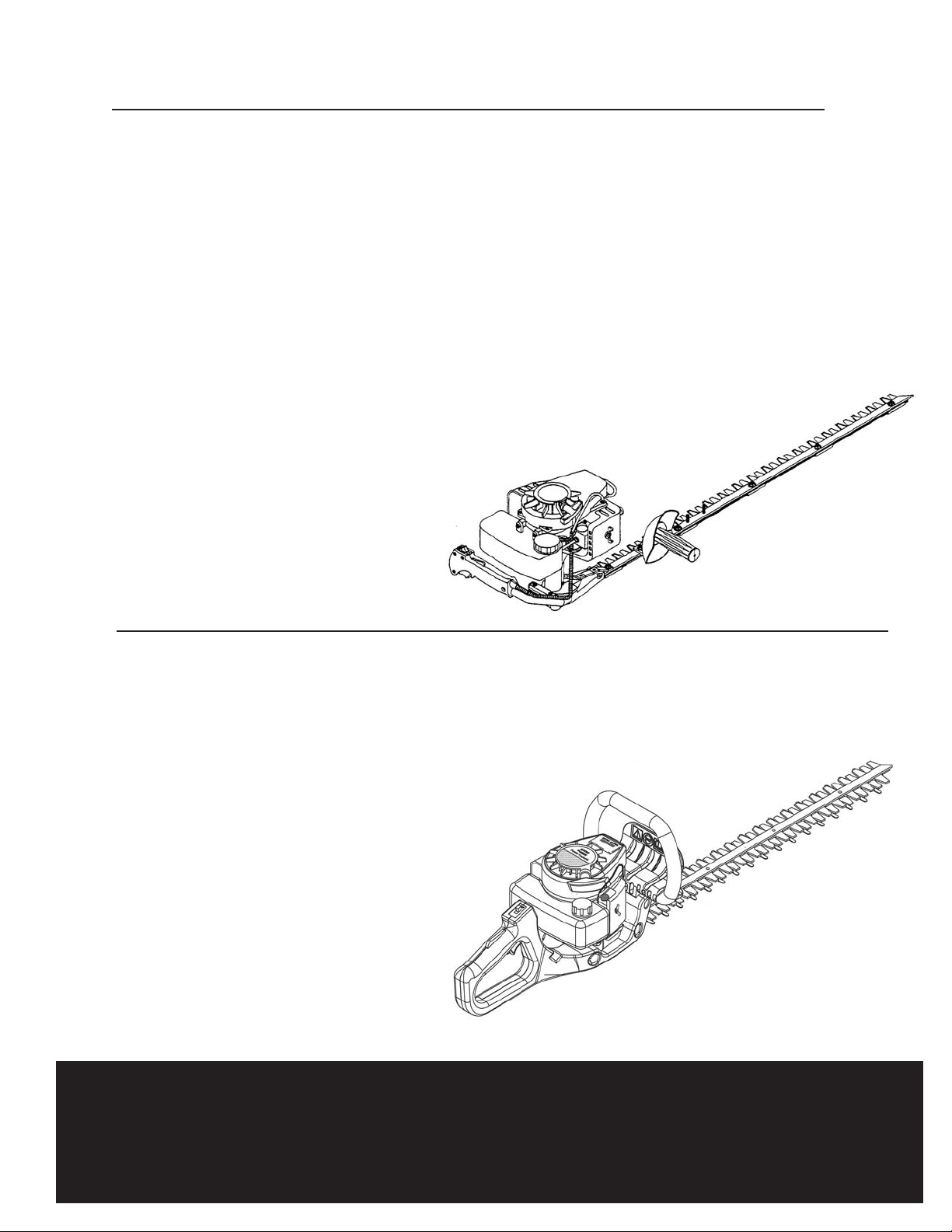
Double Edge Gasoline Hedge Trimmers
Taille-haies à double tranchant à essence
Podadoras de arbustos con motor a gasolina y
dos cuchillas
Model 2119 19"
Model 2124 24"
Model 2130 30"
Modèle 2119 19 po (48 cm)
Modèle 2124 24 po (60 cm)
Modèle 2130 30 po (76 cm)
Modelo 2119 19 pulg. (48 cm)
Modelo 2124 24 pulg. (60 cm)
Modelo 2130 30 pulg. (76 cm)
Single Edge Gasoline Hedge Trimmers
Taille-haies à un seul tranchant à essence
Podadoras de arbustos con motor a gasolina y una sola
cuchilla
Model 2230S 30"
Model 2242S 42"
Modèle 2230S 30 po (76 cm)
Modèle 2242S 42 po (106 cm)
Modelo 2230S 30 pulg. (76 cm)
Modelo 2242S 42 pulg. (106 cm)
Gas Hedge Trimmer - Owner’s Manual and Safety Instructions
Taille-haies à essence - Manuel de l’utilisateur et
Consignes de sécurité
Podadora de arbustos con motor a gasolina - Manual del propietario e
instructivo de seguridad
LITTLE WONDER
®
LITTLE WONDER
®
Page 2

Gas Hedge Trimmer -
Owner’s Manual and Safety
Instructions
Page 3
Important Information
A. Introduction.. . . . . . . . . . . . . . . . . . . . . . . . . . .3
B. Service Information . . . . . . . . . . . . . . . . . . . . .3
C. Special Safety Information . . . . . . . . . . . . . . . .3
Safety and Warnings
A. Safety Decals . . . . . . . . . . . . . . . . . . . . . . . . . .4
B. General Safety Rules. . . . . . . . . . . . . . . . . . . . .4
C. Warnings - Dont’s . . . . . . . . . . . . . . . . . . . . . .5
D. Warnings - Do’s . . . . . . . . . . . . . . . . . . . . . . . .5
E. Engine/ Fuel Warnings - Dont’s . . . . . . . . . . . .6
F. Engine/ Fuel Warnings - Do’s. . . . . . . . . . . . . .6
Assembly Instructions
A. Double Edge Models . . . . . . . . . . . . . . . . . . . .6
B. Single Edge Models... . . . . . . . . . . . . . . . . . . . .7
C. Break-In Procedure. . . . . . . . . . . . . . . . . . . . . .7
Operation
A. Fuel Mixture. . . . . . . . . . . . . . . . . . . . . . . . . . .7
B. Mixing Fuel . . . . . . . . . . . . . . . . . . . . . . . . . . . .7
C. Starting a Cold Engine. . . . . . . . . . . . . . . . . . . .8
D. Starting a Warm Engine. . . . . . . . . . . . . . . . . .8
E. Starting a Flooded Engine. . . . . . . . . . . . . . . . .8
F. Stopping the Engine . . . . . . . . . . . . . . . . . . . . .8
G. Trimming. . . . . . . . . . . . . . . . . . . . . . . . . . . . . .9
Maintenance
A. Lubrication . . . . . . . . . . . . . . . . . . . . . . . . . . . .9
B. Engine . . . . . . . . . . . . . . . . . . . . . . . . . . . . . . . .9
C. Long Term Storage (over 60 days). . . . . . . . .9
Service
A. Troubleshooting . . . . . . . . . . . . . . . . . . . . . . . .10
B. Engine Specifications . . . . . . . . . . . . . . . . . . . .10
C. Service Maintenance Guide . . . . . . . . . . . . . . .11
D. Blade Adjustment . . . . . . . . . . . . . . . . . . . . . . .11
E. Carburetor Adjustment. . . . . . . . . . . . . . . . . .12
Parts Explosions
A. Gear Housing Assembly -
Single Edge Hedge Trimmer . . . . . . . . . . . . . .13
B. Gear Housing Assembly - Double Edge
Hedge Trimmer . . . . . . . . . . . . . . . . . . . . . . . .13
C. Cutting Bar and Side Handle Assembly -
Single Edge Hedge Trimmer . . . . . . . . . . . . . .14
D. Engine and Rear Handle Assembly -
Single Edge Hedge Trimmer . . . . . . . . . . . . . .15
E. Handle Assembly - Double Edge
Hedge Trimmer . . . . . . . . . . . . . . . . . . . . . . . .16
F. Cutting Bar, Handle, and Engine Assembly -
Double Edge Hedge Trimmer . . . . . . . . . . . . .16
G. Engine SV-4B (H) Type IE . . . . . . . . . . . . . . . .17
H. Engine SV-4B (H) Type IE -
Starter, Ignition, Clutch . . . . . . . . . . . . . . . . . .19
Warranty . . . . . . . . . . . . . . . . . . . . . . . . . . .
20-21
A. Introduction
On behalf of everyone at Little Wonder, we would like to
thank you for your purchase of a Little Wonder Gasoline
Powered Hedge Trimmer. This professional trimming machine
was designed to the highest standards to ensure you many
hours of uninterrupted service.
This manual provides the information necessary for safe and
efficient operation and service. For your safety, it is critically
important that you read and understand this entire manual
before operating your hedge trimmer.
B. Service Information
Cutter Bar
Contact your local Little Wonder dealer.
Engine
Contact an authorized Echo dealer. Dealers are listed in the
Yellow Pages under “Lawn and Garden Equipment Supplies”,
“Lawn Maintenance” or “Lawn Mowers”.
C. Special Safety Information
WARNING - DANGER
ATTENTION: THIS SYMBOL POINTS OUT OUR
IMPORTANT SAFETY INSTRUCTIONS
WHEN YOU SEE THIS SYMBOL
HEED ITS WARNING! STAY ALERT!
Table of Contents
Important Information
WARNING - DANGER
TO REDUCE THE POTENTIAL FOR
ACCIDENTS, COMPLY WITH THE SAFETY
INSTRUCTIONS IN THIS MANUAL. FAILURE
TO COMPLY MAY RESULT IN SERIOUS
PERSONAL INJURY AND OR EQUIPMENT AND
WARNING - DANGER
THE ENGINE EXHAUST FROM THIS PRODUCT
CONTAINS CHEMICALS KNOWN TO THE
STATE OF CALIFORNIA TO CAUSE CANCER,
BIRTH DEFECTS OR OTHER REPRODUCTIVE
HARM.
Model
Double Edge
Single Edge
Weight, Dry
2119
x
11.7 lb.
2124
x
12.2 lb.
2130
x
12.9 lb.
2230S
x
12.25 lb.
2242S
x
13.25 lb.
Weight Specifications
3
Page 4
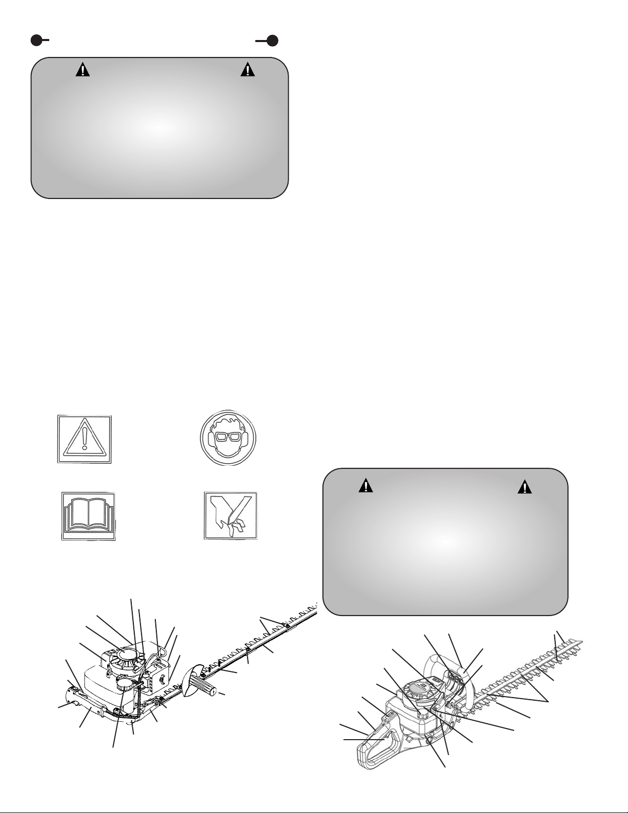
A. Safety Decals
An important part of the safety system incorporated in this
trimmer are the warning and information decals found on
various parts of the trimmer. These decals must be replaced in
time due to abrasion, etc. It is your responsibility to replace the
decals when they become hard to read. The location of these
decals and their part numbers for ordering are shown below.
B. General Safety Rules
1. THIS MACHINE CAN CAUSE SERIOUS INJURIES. Read
the instructions carefully for the correct handling, preparation,
maintenance, starting and stopping of the machine. Be familiar
with all controls and the proper use of the machine. Pay
particular attention to all sections regarding safety.
2. Always keep a firm grip on both handles while the blades
are moving and/or the engine is running. On double edge units
one hand grasps the front loop handle, while the other hand
grasps the rear handle. On single edge units the right hand
grasps the front side handle and the left hand grasps the rear
handle.
BE AWARE!!
The blades coast after throttle trigger
is released or engine is switched off. Make sure blades have
come to a complete stop and engine is off before releasing a
handle.
3. Maintain a firm footing and good balance, do not overreach
while trimming. Before you start to trim, check the work area
for obstacles that might cause you to lose your footing, balance
or control of the machine. While operating the machine always
be sure of a safe and secure operating position especially when
using steps or a ladder.
4. Keep area clear of children, pets, and bystanders.
5. Blades coast after throttle trigger is released or engine is
switched off.
6. Stop the engine before checking, maintenance or working
on the machine.
7. Never operate without guards, handles and safety devices
in place.
8. Never attempt to use an incomplete machine or one fitted
with an unauthorized modification.
9. To reduce fire hazard, keep engine and silencer free of
debris, leaves, or excessive lubricant.
10. Know how to stop the machine quickly in an emergency.
WARNING - DANGER
IMPROPER USE OR CARE OF THIS TRIMMER,
OR FAILURE TO WEAR PROPER PROTECTION
CAN RESULT IN SERIOUS INJURY.
READ AND UNDERSTAND THE RULES FOR
SAFE OPERATION AND ALL INSTRUCTIONS
IN THIS MANUAL.
WEAR HEARING PROTECTION.
WARNING!
WEAR EYE AND EAR
PROTECTION
READ AND UNDERSTAND
OWNER’S MANUAL BEFORE
USING! KEEP IN SAFE PLACE!
CUTTING HAZARD! KEEP BOTH
HANDS ON HANDLES AND
AWAY FROM BLADES!
EAR/ EYE
PROTECTION
LABEL P/N 4036
LITTLE WONDER
LABEL P/N 357
MUFFLER
LOCKOUT
TRIGGER
STOP
SWITCH
THROTTLE
TRIGGER
REAR
HANDLE
FUEL TANK CAP
GEAR HOUSING
WARNING LABEL P/N 300605
MODEL NO. LABEL
FRONT SIDE HANDLE
ADJUSTING
SCREW AND
BLADE GUARD
FRAME
BAR
STARTER HANDLE
SPARK PLUG WIRE
THROTTLE CABLE
PRIMER BULB
AIR CLEANER
CHOKE KNOB
CUTTING
BLADES
MUFFLER
FUEL TANK CAP
SERIAL NO.
LOOP HANDLE
CHOKE
KNOB
CUTTING
BLADES
FRAME BAR
ADJUSTING
SCREW & NUT
SAFETY COMB
STARTER HANDLE
AIR CLEANER
GEAR HOUSING
THROTTLE TRIGGER
REAR HANDLE
LOCK OUT TRIGGER
STOP SWITCH
WARNING SYMBOLS
PRIMER BULB
SPARK PLUG WIRE
4
Safety and Warnings
WARNING - DANGER
IF TRIMMER IS USED IMPROPERLY OR SAFETY
PRECAUTIONS ARE NOT FOLLOWED. THE
USER RISKS SERIOUS INJURY TO
THEMSELVES AND OTHERS.
READ AND UNDERSTAND THE FOLLOWING
BEFORE ATTEMPTING
TO OPERATE THIS HEDGE TRIMMER
Page 5
5
C. Warnings - Don’ts
Don’t use trimmer with one hand, keep both hands on handles
with fingers and thumbs encircling the handles, while blades are
moving, and engine is running.
Don’t overreach or stand on unstable support. Do not stand
on the top of a ladder while trimming. Use proper equipment
for reaching higher heights. Keep a good footing at all times.
Don’t ever grasp cutting blades for any reason.
Don’t operate the machine with a damaged or excessively
worn cutting device.
Don’t attempt to clear cut material while blades are moving,
and the engine is running. Never try to remove jammed
material before switching the engine off and making sure the
blades have stopped completely.
Don’t override safety features.
Don’t allow children or incapable people to operate this
trimmer.
Don’t operate this hedge trimmer while under the influence of
alcohol or drugs.
Don’t attempt to repair this hedge trimmer. Have repairs
made by a qualified dealer or repairman. See that only original
Little Wonder parts are used.
D. Warnings - Do’s
Always read and follow all instructions.
Always stay alert. Watch what you are doing and use common
sense. Do not operate unit when fatigued.
Always dress properly. Do not wear loose clothing or jewelry,
they might get caught in moving parts. Use sturdy proper fitting,
non-slip gloves. Gloves reduce the transmission of vibration to
your hands. Prolonged exposure to vibration can cause
numbness and other ailments. Wear non-skid foot wear to
ensure secure and proper footing.
Always wear ear and eye protection. Eye protection must
meet ANSI Z 87.1. To avoid hearing damage we recommend
hearing protection be worn whenever using the equipment.
Always keep both hands on both handles when trimmer is
running. Severe injuries can result if you try to use the hedge
trimmer with only one hand or with an insecure grip.
Always keep children, pets, and incapable persons away.
Always use trimmer properly. Cut only types and size of
growth described in the Trimming section of this manual.
Overloading or abusing your hedge trimmer can cause
premature failure and can result in injury. Use common sense.
Always keep a safe distance between two or more operators
when working together simultaneously.
Always inspect your unit before each use and ensure that all
handles, guards, safety devices and fasteners are secure,
operating, and in place.
Always maintain and examine your trimmer with care. Follow
maintenance instructions given in manual.
Always store trimmer in a sheltered area (a dry place) not
accessible to children. The hedge trimmer as well as fuel should
not be stored in a house.
Always be aware of your surroundings and stay alert for
possible hazards that you may not hear due to the noise of the
machine.
Always fit the cutting device guard when transporting or
storing the machine.
WARNING - DANGER
IF TRIMMER IS USED IMPROPERLY OR SAFETY
PRECAUTIONS ARE NOT FOLLOWED, THE
USER RISKS SERIOUS INJURY TO THEMSELVES
AND OTHERS.
READ AND UNDERSTAND THE FOLLOWING
BEFORE ATTEMPTING TO OPERATE THIS
HEDGE TRIMMER.
WARNING - DANGER
HANDLE FUEL WITH CARE. IT IS HIGHLY
FLAMMABLE. FUELING A HOT ENGINE OR
NEAR AN IGNITION SOURCE CAN CAUSE A
FIRE AND RESULT IN SERIOUS PERSONAL
INJURY AND/ OR PROPERTY DAMAGE.
Page 6
E. Engine/ Fuel Warnings - Don’ts
Don’t fuel, refuel or check fuel while smoking or near an open
flame or other ignition source. Stop engine and be sure it is
cool before refueling.
Don’t leave the engine running while the trimmer is
unattended. Stop engine before putting the trimmer down or
while transporting from one place to another.
Don’t start, run this trimmer indoors, or in an improperly
ventilated area as poisonous carbon monoxide and other gasses
are emitted.
Don’t run engine when electrical system causes spark outside
the cylinder. During periodical checks of the spark plug, keep
plug a safe distance from cylinder to avoid burning of
evaporated fuel from cylinder.
Don’t check for spark with spark plug or plug wire removed
and grounded. Use an approved tester. Sparks can ignite fumes.
Don’t crank engine with spark plug removed. If the engine is
flooded, open the choke (push choke knob in) and pull recoil
until engine starts. If this fails read and follow section IV. E. of
this manual.
Don’t run engine when the odor of gasoline is present or
other explosive conditions exist.
Don’t operate the unit if gasoline is spilled. Clean up spill
completely before starting engine.
Don’t refuel indoors or in an improperly ventilated area.
Don’t operate your trimmer if there is an accumulation of
debris around the muffler, and cooling fins.
Don’t touch hot mufflers, cylinders or cooling fins as contact
may cause serious burns.
F. Engine/ Fuel Warnings - Do’s
Always use fresh gasoline in the fuel mixture. Stale gasoline can
cause leakage.
Always pull starter cord slowly until resistance is felt. Then
pull cord rapidly to avoid kickback and prevent arm or hand
injury.
Always operate engine with spark arrestor installed and
operating properly. The use of spark arrestor mufflers is
required by law in the state of California (Section 4442 of the
California Public Resources Code), as well as in other states or
municipalities. Federal laws
apply on federal lands.
This spark ignition system
meets all requirements of
Canadian Interference-causing
Equipment Regulations.
Always handle fuel with
care; it is highly flammable.
Never add fuel to a machine
with a running or hot engine.
Do not inhale fuel fumes as
they are toxic.
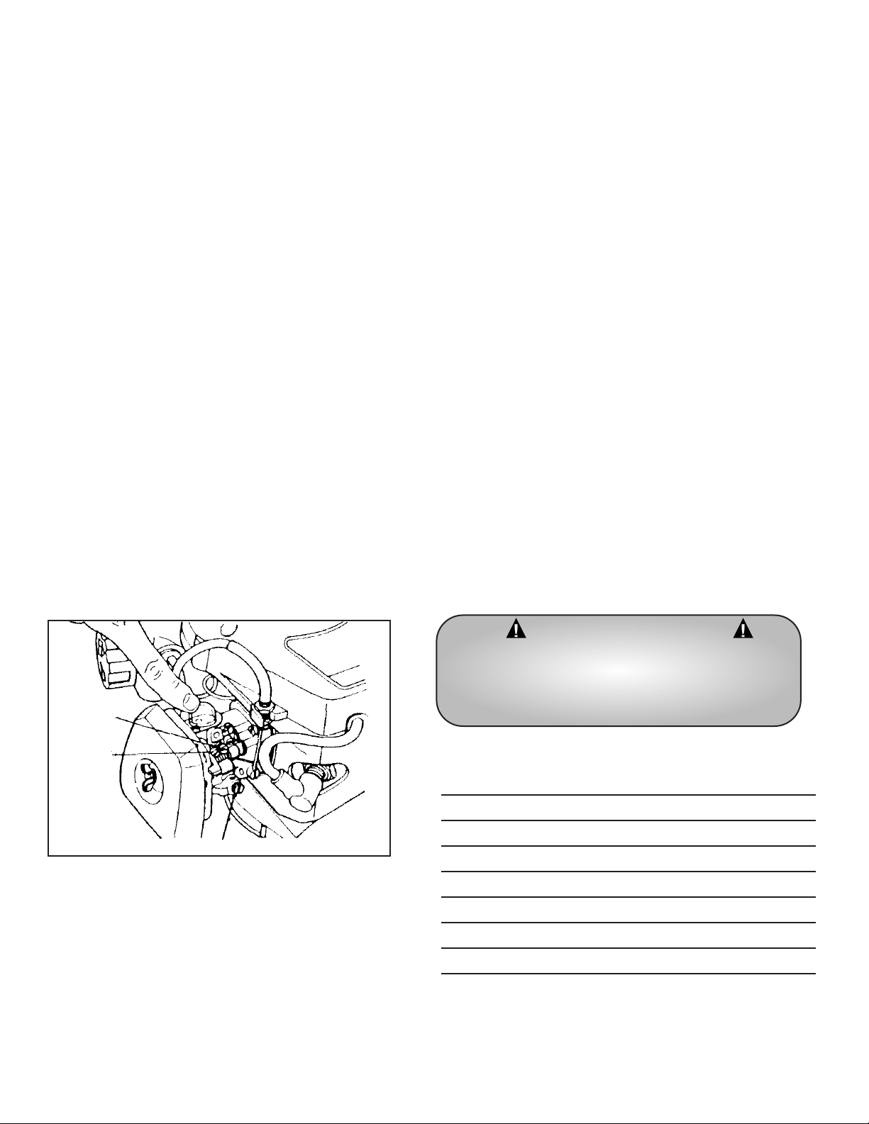
Your Little Wonder hedge trimmer has been assembled for
you at the factory. Before operating be sure all fasteners are
secure, and all guards and safety devices are in place and
operating properly.
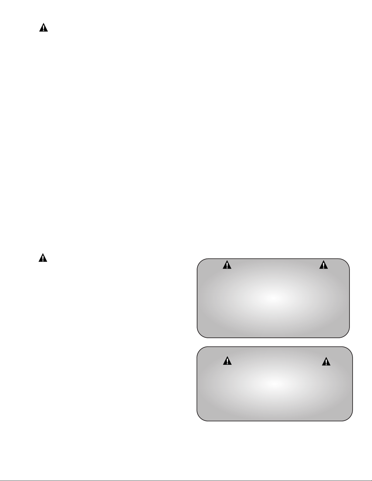
A. Double Edge Models
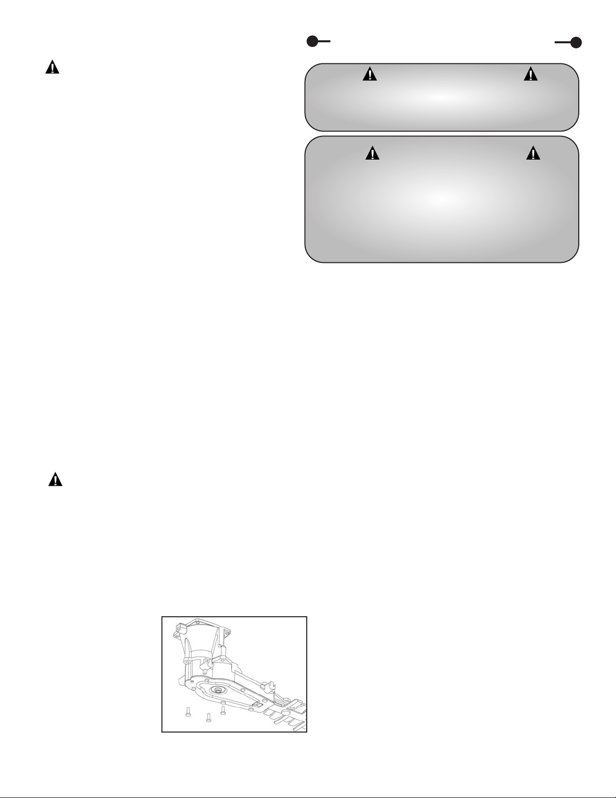
If the engine needs to be reinstalled:
1. Install the engine by first aligning the hex drive on the
trimmer gear housing with the hex socket of the engine’s clutch
drum.
2. Slide the engine with the attached engine adapter over he
gear housing stem until it is seated all the way down on the
gear housing.
3. Align the three threaded holes of the engine adapter with
the mounting holes of the gear housing.
4. Use three 8-32 x 5/8 screws with the attached dual action
spring washers. See Figure 1.
5. Release the throttle trigger and make sure the throttle
returns to the idle position, when the carburetor level rests on
the idle screw. Throttle movement should be smooth and
unobstructed.
B. Single Edge Models
1. Remove the cutter bar assembly, the engine with handle and
throttle assembly, the side handle, and hardware bag from their
boxes.
P/N Description Qty.
972 1/4-20 Lock Nut 2
300102 Handle Support Channel 2
300113 Spacer Tube 2
300111 Shock Absorber 4
300112 Support Plate 1
300505 1/4-20 x 2 21/2 2
3036-B 1/4-28 Flange Locknut 2
6
Assembly Instructions
WARNING - DANGER
BLADES ARE EXTREMELY SHARP! TO AVOID
INJURY WHEN UNPACKING THE HEDGE
TRIMMER, DO NOT GRASP THE BLADES.
WARNING - DANGER
IMPROPER ASSEMBLY OF THIS TRIMMER CAN
RESULT IN SERIOUS INJURY. MAKE SURE TO
FOLLOW ALL INSTRUCTIONS CAREFULLY.
IF YOU HAVE ANY QUESTIONS, CONTACT
YOUR LOCAL DEALER OR OUR FACTORY
AT (215) 357-5110.
Figure 1
Page 7
7
Operation
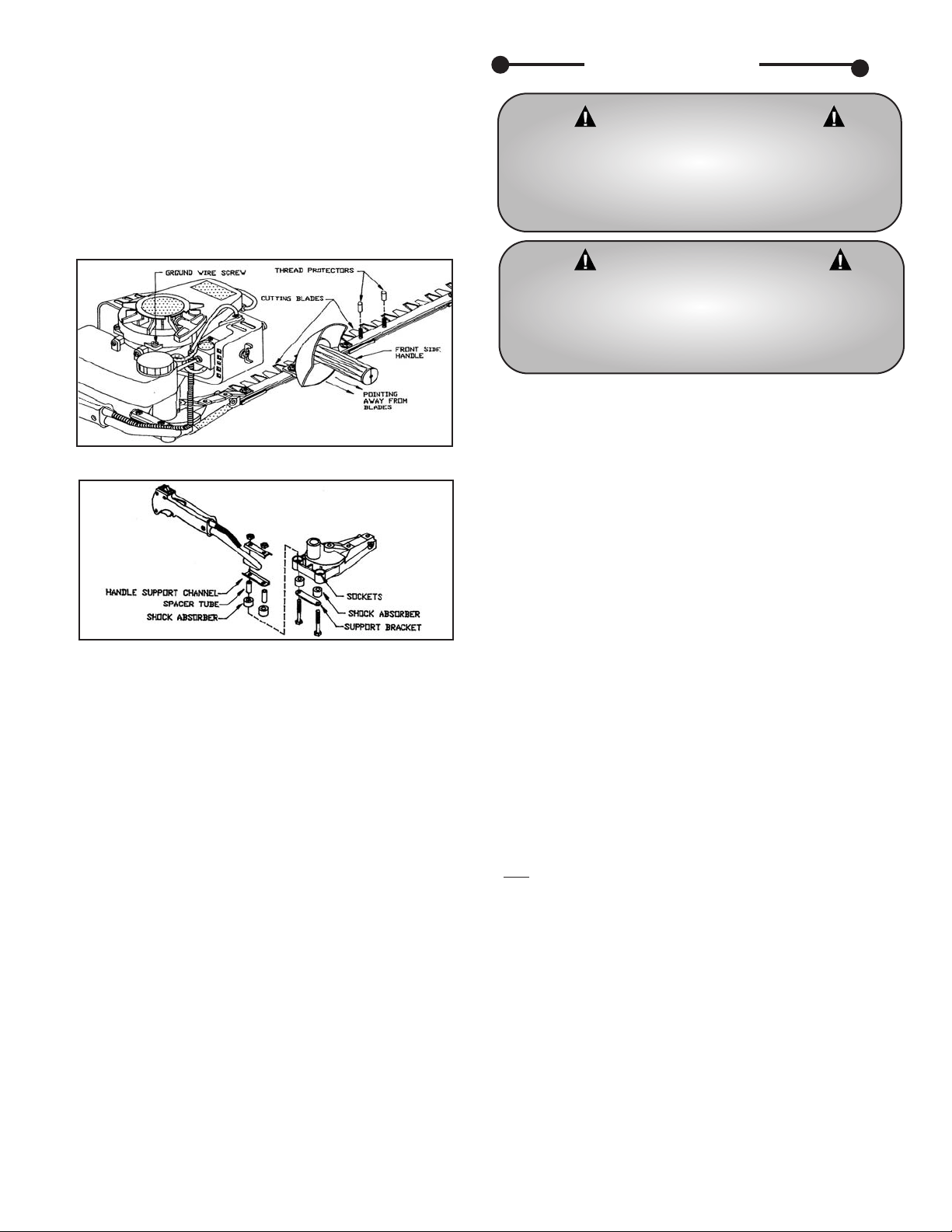
2. Place the front side handle over the two 1/4-28 studs
protruding from the frame bar in front of the gear housing. The
handle grip must be pointing away from the cutting blades as
illustrated (Figure 1). On Model 2230S use the set of studs
which places the handle in the most comfortable position for
you. Place the thread protectors over the set of studs that you
choose not to use at this time to protect the threads. Secure
the handle in place using two 1/4-28 flange locking nuts
provided. The nuts should be tightened enough to keep the
handle from moving but not so tight as to crush the plastic.
If the engine needs to be reinstalled:
1. Install the engine by first aligning the hex drive on the
trimmer gear housing with the single sided hex socket in the
engine.
2. Slide the engine over the 1" diameter stem containing
the hex drive on the gear housing until it is seated all the way
down on the gear housing. Tighten the 7/8" Phillips Pan Head
Screw (Pg. 12, Key #22).
3. Press shock absorbers into sockets on the gear housing
followed by the spacer tubes. Secure the handle and tubing
support channel, spacer, and bracket with the 1/4-20 hex bolts
and locking nuts supplied.
4. With the stop switch in the stop position, and the
engine not running, check the throttle for proper operation.
Grasp rear handle with left hand, depressing the lockout trigger
until it stops when the carburetor lever hits the carburetor
case. Release the throttle trigger and make sure the throttle
returns to the idle position, when the carburetor level rests on
the idle screw. Throttle movement should be smooth and
unobstructed.
C. Break-In Procedure
There are no special requirements for engine break-in. After
normal operation and two (2) tanks of fuel, engine break-in is
complete.
If adjustments are necessary, follow Special Carburetor
Adjustment Procedures on this supplementary Operator's
Information Sheet. All other adjustments and maintenance
procedures are in the complete Owner’s Manual.
A. Fuel Mixture
Your Little Wonder Single Edge Hedge Trimmer is powered by
an Echo Model SV-4B(H) Type IE, and Double Edge Hedge
Trimmer is powered by an Echo Model SV-4B(H2) Type IE.
Both models have two stroke, air cooled engines which require
a fuel mixture of gasoline and 2-stroke oil.
1. Important Engine Information
This unit is certified to operate on approved two-stroke fuel
(a mixture of 2-stroke oil and gasoline/ gasohol).
2. Fuel Statement
Gasoline - Use 89 Octane [R+M/2] gasoline or gasohol
known to be good quality. Gasohol may contain up to 10%
Ethanol (grain alcohol) or 15% MTBE (methyl tertiary-butyl
ether). Gasohol containing methanol (wood alcohol) is NOT
approved.
3. Two-Stroke Oil
A two-stroke engine oil meeting proposed ISO-L-EGD
Standard (ISO/CD 13738), must be used. LW brand Premium
50:1 oil meets this proposed standard. Engine problems due to inadequate lubrication caused by failure to use an ISO-L-EGD
approved oil, such as LW Premium 50:1 Two-stroke Oil, will
void the two-stroke engine warranty. (Emission related parts
only
are covered for two years, regardless of two-stroke oil used,
per the statement listed in the EPA Phase I/California Emission
Defect Warranty Explanation.)
B. Mixing Fuel
1. Pour 1/2 of the gasoline into a safe container. DO NOT
mix fuel in the engine fuel tank.
2. Add the oil to the gasoline and mix.
3. Add the remaining gasoline and remix.
4. Install fuel cap and wipe spilled fuel from container and area.
5. Important, two stroke fuel separates and ages. Do not mix
more than you will use in a month. Shake fuel container to
thoroughly mix fuel before each use. Do not attempt to run
your engine on gasoline only, use the proper fuel mixture.
WARNING - DANGER
THE OPERATOR OF THIS HEDGE TRIMMER IS
RESPONSIBLE FOR ACCIDENTS OR HAZARDS
OCCURRING TO HIMSELF, OTHER PEOPLE OR
THEIR PROPERTY.
WARNING - DANGER
FUEL IS EXTREMELY FLAMMABLE. HANDLE
IT WITH CARE. KEEP AWAY FROM IGNITION
SOURCES. DO NOT SMOKE WHILE FUELING
YOUR EQUIPMENT.
Figure 1
Figure 2
Page 8
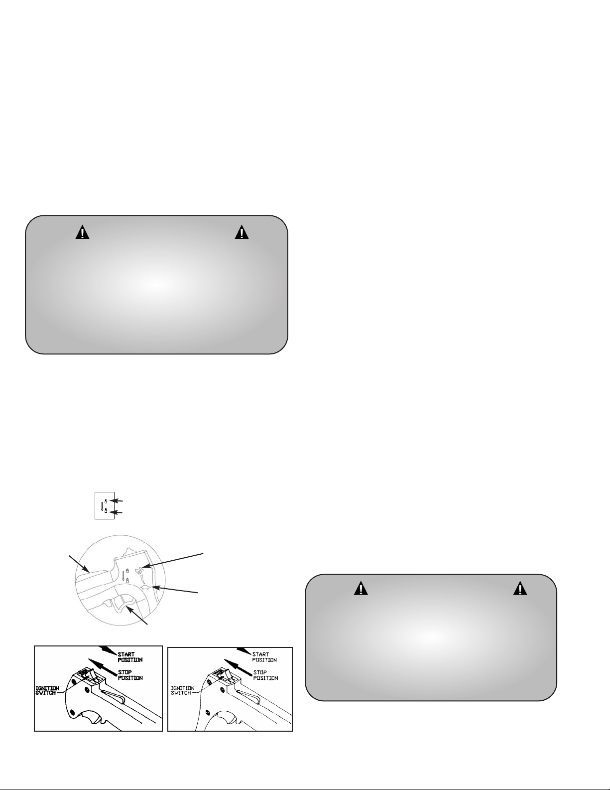
C. Starting a Cold Engine
The trimmer has a Start/Stop ignition switch which must be used
for starting and stopping the engine.
1. Place the hedge trimmer flat on the ground, or another
stable surface. Slide the ignition switch to the START position.
2. Pull choke knob out to COLD START (closed) position.
3. Push primer bulb 3 to 4 times, or until fuel is visible in the
clear fuel return line.
4. Pull starter rope until engine sputters.
Use short pulls, 1/2 to
2/3 of the rope length.
5. Push choke knob in to the RUN position.
6. Restart engine and allow it to warm up for 2-3 minutes.
7. With both hands on the handles, squeeze throttle trigger
gradually, to increase the engine speed and engage the blades.
NOTE: Allow engine to warm up 2-3 minutes before use. Failure
to do so will cause engine damage.
D. Starting a Warm Engine
1. Slide ignition switch to START position.
2. Push choke knob in to RUN (open) position.
3. If there is no fuel in the clear return line, push primer bulb
3-4 times or until fuel is visible in the line.
4. Pull starter rope using short pulls, 1/2 to 2/3 of the rope
length.
5. If engine fails to start in 4 pulls, use cold start procedure.
6.
With both hands on the handles, squeeze throttle trigger
gradually to increase
the engine speed and engage the blades.
E. Starting a Flooded Engine
1. Remove the cap from the spark plug and unscrew the plug
with a spark plug wrench. If the end of the spark plug is wet, the
engine may be flooded.
2. Use a paper towel or clean rag to dry the end of the spark
plug.
3. Reinstall the spark plug and cap.
4. Push the choke knob in (open position) and pull starter rope
three to four times.
5. Now pull the choke knob out (closed position) and pull the
starter rope until the engine sputters.
6. Finally, push the choke knob in (open position) and pull the
starter rope to start the engine
F. Stopping the Engine
1. Release the throttle trigger and allow engine to idle.
2.
Slide ignition switch to the STOP position.
3. Make sure blades have come to a complete stop before
releasing either handle.
8
Single Edge Trimmer
Double Edge Trimmer
WARNING - DANGER
AVOID ACCIDENTAL BLADE ENGAGEMENT.
DO NOT SQUEEZE TRIGGER WHEN STARTING.
MAINTAIN ENGINE’S PROPER IDLE SPEED
ADJUSTMENT (2500 - 2700 RPM)
MAX FULL THROTTLE ENGINE SPEED IS
10,500 - 11,000 RPM
WARNING - DANGER
IF ENGINE DOES NOT STOP WHEN SWITCH IS
PUT IN THE STOP POSITION, RELEASE THE
THROTTLE TRIGGER, ALLOW ENGINE TO
IDLE.
PUT THE TRIMMER DOWN, AND PULL THE
CHOKE KNOB OUT TO COLD STOP,
(CLOSED) POSITION.
Fast
Locked
Unlocked
Slow
Lockout
trigger
Throttle trigger
Squeeze trigger to increase speed
Page 9
9
G. Trimming
1. WARNING! Read and follow all safety instructions in the
manual before attempting to use this trimmer.
2. Only after you are familiar with your hedge trimmer and all
of its controls and the functions should you start the engine.
3. Once the engine is started grasp the handles securely, the
left hand should grasp the rear handle and the right hand should
grasp the front side handle on single edge trimmers. On double
edge trimmers, one hand grasps the front loop handle, while
the other hand grasps the rear handle.
4. Squeeze the throttle to accelerate the engine and engage
the blades.
5. Tilt the trimmer so the cutting teeth are angled slightly
toward the hedge or shrub and proceed to cut. Use
overlapping sweeping motions away from your body to achieve
a safe and even cut.
6. This unit is designed to cut any type of hedge or shrub;
however,
THICKNESS OF CUT SHOULD NOT EXCEED 1
INCH IN DIAMETER.
Misuse of this Hedge Trimmer will void the
warranty. ie: Cutting hedges or shrubs over 1" in
diameter or foreign objects such as wires, rocks, or
fences. Before trimming check work area for foreign
objects such as wires, cords, glass, fences, or rocks. Be
sure to remove any foreign objects from the work area. Failure to
properly maintain this hedge trimmer will void the warranty.
A. Lubrication
1. A few drops of a light #10 oil should be placed on the back
edge of each blade guard at each adjusting screw approximately
after every 4 hours of normal operation.
2. To obtain trouble free trimming, it is necessary to keep the
blades lubricated and clean. The gum that collects and builds up on
the blades can be removed with a 50-50 mixture of kerosene and
#10 oil. As petroleum products can shorten the life of some
plastics it is necessary to remove excess oil-kerosene mixture from
the plastic parts.
3. When blades are replaced, or any other time that the
bottom cover plate is removed, the grease level should be checked
for proper amount (approximately 3/4 full in the area of the gears)
and a new gasket (P/N319) should be used to insure proper seating
of the cover plate. Grease level should be checked and adjusted
after every 50 hours of use. Use only Lubrico M3-3K-9K
(P/N 16-78A) grease in the gear housing.
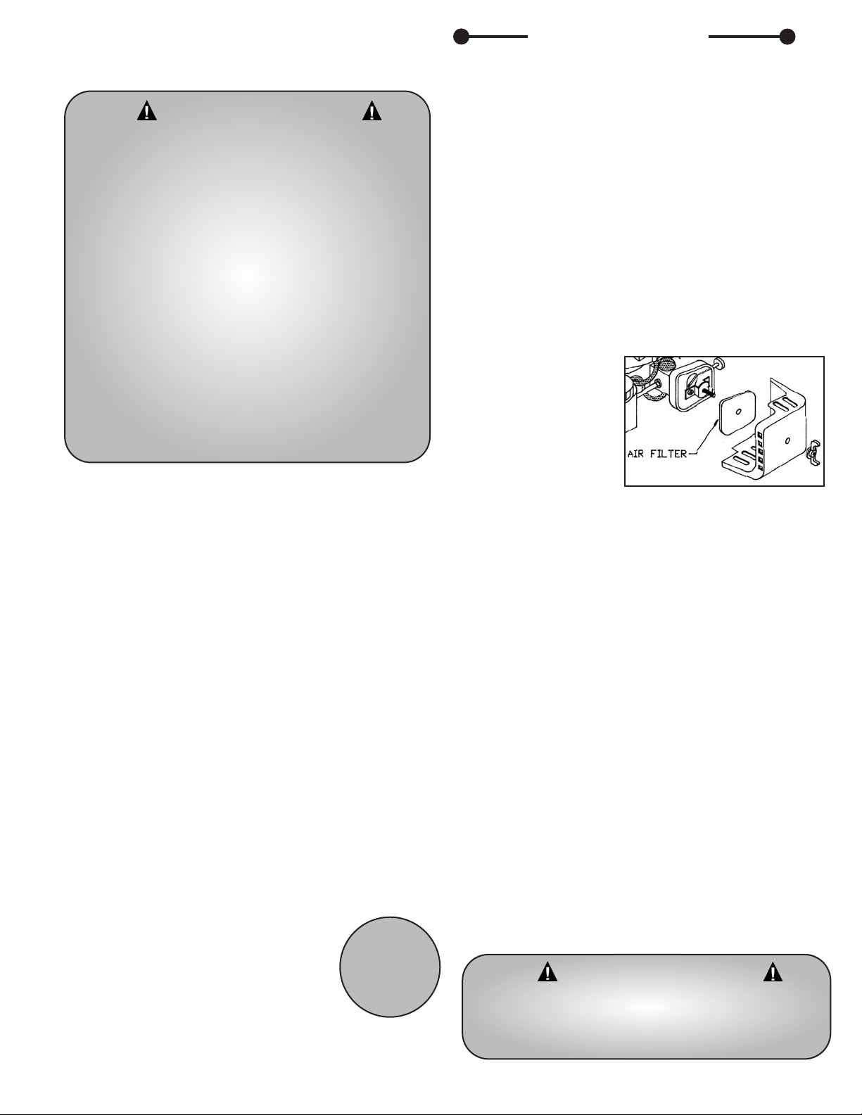
B. Engine
1. Air Filter
a. Clean the air filter
before each use. Remove wing
nut and air filter cover.
b. If filter is
excessively dirty or no longer
fits properly, replace it.
c. Re-install filter to
inside cover making sure it is
seated properly.
d. Re-install cover onto air cleaner case and secure with
wing nut.
2. Cooling Fins
Remove dirt and debris from around cooling fins and
exhaust before each use. Proper air circulation is essential for
engine performance and life.
C. Long Term Storage (over 60 days)
1. Store your trimmer in a dry and dust free space, out of the
reach of children.
2. Place the ignition switch in the stop position.
3. Clean the engine and blades thoroughly and coat the blades
with #10 oil to prevent rust.
4. Perform all required maintenance and service found in
this manual.
5. Drain the fuel tank and pull the starter rope several times
to remove the fuel from the carburetor.
6. Remove the spark plug and pour 1/4 oz. of fresh, clean,
two-stroke engine oil into the cylinder via the spark plug hole.
Cover the hole with a rag and pull the starter rope 2-3 times.
7. While looking through the spark plug hole pull the starter
rope until the piston reaches the top of its stroke and stop.
8. Install the spark plug, but leave the ignition cable
disconnected.
WARNING - DANGER
BLADES COAST AFTER RELEASING THROTTLE
OR STOPPING ENGINE.
KEEP A FIRM GRIP WITH BOTH HANDS WHILE
BLADES ARE MOVING AND/ OR ENGINE
IS RUNNING.
DO NOT STAND ON THE TOP OF A LADDER
WHILE TRIMMING.
MAKE SURE YOUR LADDER OR OTHER
SUPPORT IS STABLE AND ON FIRM GROUND.
KEEP A SURE FOOTING. DO NOT OVERREACH.
IF YOUR TRIMMER BECOMES JAMMED, RELEASE
THROTTLE AND STOP ENGINE. MAKE SURE
BLADES HAVE STOPPED COMPLETELY, THEN
REMOVE THE OBSTRUCTION.
1"
diameter
Maintenance
WARNING - DANGER
DO NOT STORE IN AN AREA WHERE FUEL FUMES
MAY ACCUMULATE AND REACH A FLAME
OR SPARK.
Page 10

10
B. Engine Specifications
Dry Weight 2.5 kg –– 5 lbs., 10 ounces
Type of Engine Air Cooled, Two stroke, Single-
Cylinder, Gasoline Engine
Rotation Counterclockwise, viewed from TOP
Bore 32.2 mm (1.268 in.)
Stroke 26.0 mm (1.04 in. )
Spark Plug NGK BPM7Y, Champion RCJ-7Y or
RCJ-8Y The spark plug gap is
0.65 mm (0.026”).
Refer to Owner’s Manual, for
service Procedure
Fuel Premixed two stroke fuel
Fuel Oil Ratio 50:1 ratio with ECHO or Little
Wonder oil
Gasoline Unleaded, 89 octane or higher
Displacement 21.2 cc (1.294 cu. in.)
Exhaust System Spark arrester muffler
Carburetor ZAMA diaphragm model C1U type.
RPM at idle 2800
+
-
250 RPM
Ignition System There are no adjustments required
for the ignition
Service
Problem
1. Blades don’t cut
cleanly.
2. Blades don’t
move when
throttle is
depressed.
3. Engine fails to
start
4. Engine hard to
start.
5. Engine misses.
6. Engine lacks
power.
7. Engine
overheats.
8. Engine noisy or
knocking.
9. Engine stalls
under load.
Cause
Blades are dull or not adjusted properly.
Engine is not seated properly on the gear
housing.
Blades are adjusted too tight.
ON/OFF switch is in OFF position.
No fuel in tank.
Fuel strainer clogged.
Fuel line clogged.
Spark plug shorted or fouled.
Spark plug is broken (cracked porcelain or
electrodes broken).
Ignition lead wire shorted, broken or
disconnected from spark plug.
Ignition inoperative (no spark from lead
wire).
Water in gasoline or stale fuel mixture.
Too much oil in fuel mixture.
Engine under or over choked.
Carburetor out of adjustment.
Gasket leaks (carburetor or
cylinder base gasket).
Weak spark at sparkplug
Air cleaner clogged.
Carburetor out of adjustment.
Muffler clogged.
Clogged exhaust ports.
Clogged spark arrestor
Poor compression.
Insufficient oil in fuel mixture.
Air flow obstructed.
Loose flywheel.
Spark plugs incorrect heat range.
Worn bearings, piston ring or cylinder walls.
Carburetor adjustment too “lean”.
Engine overheats.
Remedy
Have blades sharpened and adjusted.
Re-install engine following the assembly instructions. (pg. 4)
Re-adjust blades following service instructions. (pg. 9)
Move switch to ON.
Fill Tank.
Replace Strainer.
Clean fuel line.
Install new sparkplug.
Replace sparkplug.
Replace lead wire or attach to sparkplug.
Contact your nearest authorized dealer.
Drain entire system and refill with fresh fuel.
Drain and refill with correct mixture. If flooded by over
choking, proceed according to instructions in operation
section. If under choked, move choke lever to closed position
and crank two or three times. See “Carburetor Adjustment”
Replace gaskets. (pg. 10)
Contact your nearest authorized dealer.
Remove and clean. See “Carburetor Adjustment”. (pg. 10)
Clean or replace spark plug - set gap to 0.6-0.7 mm (.024
.028in.).
Contact your nearest authorized dealer.
Clean air cleaner.
See “Carburetor Adjustment”.
Clean carbon from muffler.
Remove muffler, rotate engine until the piston is at top of
cylinder. With a wooden scraper or blunt tool, remove all
carbon from exhaust ports. Be careful not to scratch or
damage piston or cylinder walls. Blow out all loose carbon
with compressed air. Install muffler and gasket.
Clean
Contact your nearest authorized dealer.
Mix fuel as described in starting instructions.
Clean flywheel, cylinder fins and screen.
Tighten flywheel nut.
Replace with plugs specified for engine.
Contact your nearest authorized dealer.
See “Carburetor Adjustment”.
Remove dust and dirt from between cylinder fins.
A. Troubleshooting
Page 11

11
Area
Air Filter
Fuel Filter
Spark Plug
Carburetor
Cooling System
Muffler (Spark Arrestor)
Gear Housing
Blades
Fuel Leaks
Fasteners
Labels
Handles
Guards / Safety Devices
Fuel Line
Starter Rope
Fuel Strainer
Choke
Ignition System
Maintenance
Clean
Replace
Inspect / Replace
Clean
Replace
Check / Rebuild
Replace
Inspect / Clean
Inspect / Clean
Check Grease
Inspect / Clean / Lubricate
Inspect / Repair
Inspect / Tighten / Replace
Inspect / Replace
Inspect / Replace
Inspect / Replace
Inspect / Replace
Inspect / Replace
Replace
Check
Clean
Replace
Frequency
Daily or every 4 hrs. use
Every 3 mths. or 100 hrs. use
Monthly
Every 3 mths. or 100 hrs. use
6 months or 300 hrs. use
6 months or 300 hrs. use
Yearly or 600 Hrs. use
†
Before Use
Monthly
Every 50 hours of use
After Use
Before Use
Before Use
Before Use
Before Use
Before Use
Monthly
Monthly
Every 3 mths. or 100 hrs. use
With each re-fueling
No maintenance
For coil and flywheel
C. Service Maintenance Guide
†
Replacement will be required for commercial use after 600 hours. For customer use, cleaning every six months is required.
Cleaning includes rebuild kits.
IMPORTANT: Time intervals shown are maximum. Actual use and your experience will determine the frequency of required
maintenance.
D. Blade Adjustment and Comb
Orientation
The care and adjustment of the blades is very important to the
efficient operation of the trimmer and especially to the long life of
the engine.
1. Place trimmer in vise, clamping on the frame bar. Be careful!
Blades are sharp!
2. Using a 7/16” wrench, loosen all blade locknuts and unscrew the
large head screws by two turns.
3. Starting with the screw nearest the gear housing, tighten the
screw until the blade guard of the single edge trimmer or the
protective comb of the double edge trimmer
can just be moved with finger pressure and a .0015" (1 1/2 thou.)
feeler blade just slips under the blade guard or comb. Tighten the
locknuts while holding the screw stationary in its correct adjusted
position.
4. Repeat Step 3 on the screws in turn until all are correctly
adjusted.
5. Orientation of the comb is very important. The comb has
staggered teeth for better cutting performance. Correct comb
orientation is shown below.
NOTE: Correct blade adjustment can only be achieved on
clean,
oiled blades.
Single Edge Double Edge Comb Orientation
Page 12
12
E. Carburetor Adjustment
1. General
NOTE: The diaphragm carburetor has three external
adjustments. Each adjustment affects the others.
The idle speed adjustment screw controls the throttle opening
at idle position.
The low (LO) speed adjustment screw controls the volume of
fuel mixture at low engine speed. It also controls the
supplementary fuel required to obtain smooth progression from
idling to high speed.
The high (HI) speed adjustment screw controls the volume of
fuel mixture at full throttle.
2. Carburetor Adjustment
Every unit is run at the factory and the carburetor is set in
compliance with EPA Phase I / California Emission Regulations.
In addition, the carburetor is equipped with HI and LO needle
adjustment limiters that prevent settings outside acceptable
limits. Limiter caps must remain or be replaced on both the Hi
and Lo carburetor adjusting screws. There is no limiter cap on
the idle screw.
NOTE: The needle screws have a sharp point. To avoid damage
to the carburetor, do not use excessive force.
a. Before adjusting carburetor clean or replace air filter and
muffler, "Spark Arrestor Screen".
b. Make sure the cutting attachment such as hedge clipper
blades are properly adjusted.
c. Start engine and run several minutes to bring to operating
temperature. Flash choke twice during warm-up to clear any
air from the fuel system.
NOTE: The Idle speed screws may have to be re-adjusted to
keep engine from stalling. The Engine must be at normal
operating temperature to adjust properly.
d. Stop engine. Turn HI speed needle counter-clockwise to
stop. Turn LO speed needle midway between full clockwise
stop and counter-clockwise stop.
e. Idle Speed Adjustment
Units with Cutting Attachments.
Turn "idle" speed adjustment screw CW (clockwise) until
cutting attachment begins to turn, then turn screw out
CCW (counter clockwise) until attachment stops turning.
Turn screw out, CCW, an additional 1/4 turn.
f. Start unit and accelerate to full throttle for 2-3 seconds to
clear any excess fuel in the engine, then return to idle.
Accelerate engine to full throttle to check for smooth
transition from idle to high speed. If engine hesitates turn
LO needle CCW 1/8 turn and repeat acceleration. Continue
adjustment until smooth acceleration results.
g. Check idle speed and reset if necessary as described in
“item e” above. If a tachometer is available idle speed
should be set as specified in the Owner’s Manual.
Important: Do not run the engine at full throttle or with no
load for more than 5-6 seconds to avoid engine damage.
Note: This hedge trimmer is equipped with a speed limiting
carburetor (the high speed circuit has a by-pass system). With
this feature the engine will continue to run even with the high
speed adjusting screw turned all the way in. Although the
engine will continue to run, it will only produce full power with
the HI adjusting screw opened to about 3/8 to 1/2 turn.
WARNING - DANGER
KEEP HANDS AWAY FROM THE BLADES WHILE
SERVICING THE HEDGE TRIMMER. BE SURE
TRIMMER IS SECURED AND BLADES ARE
GUARDED WHILE MAKING ADJUSTMENTS.
F. Notes
HI
LOW
IDLE SCREW
Page 13
13
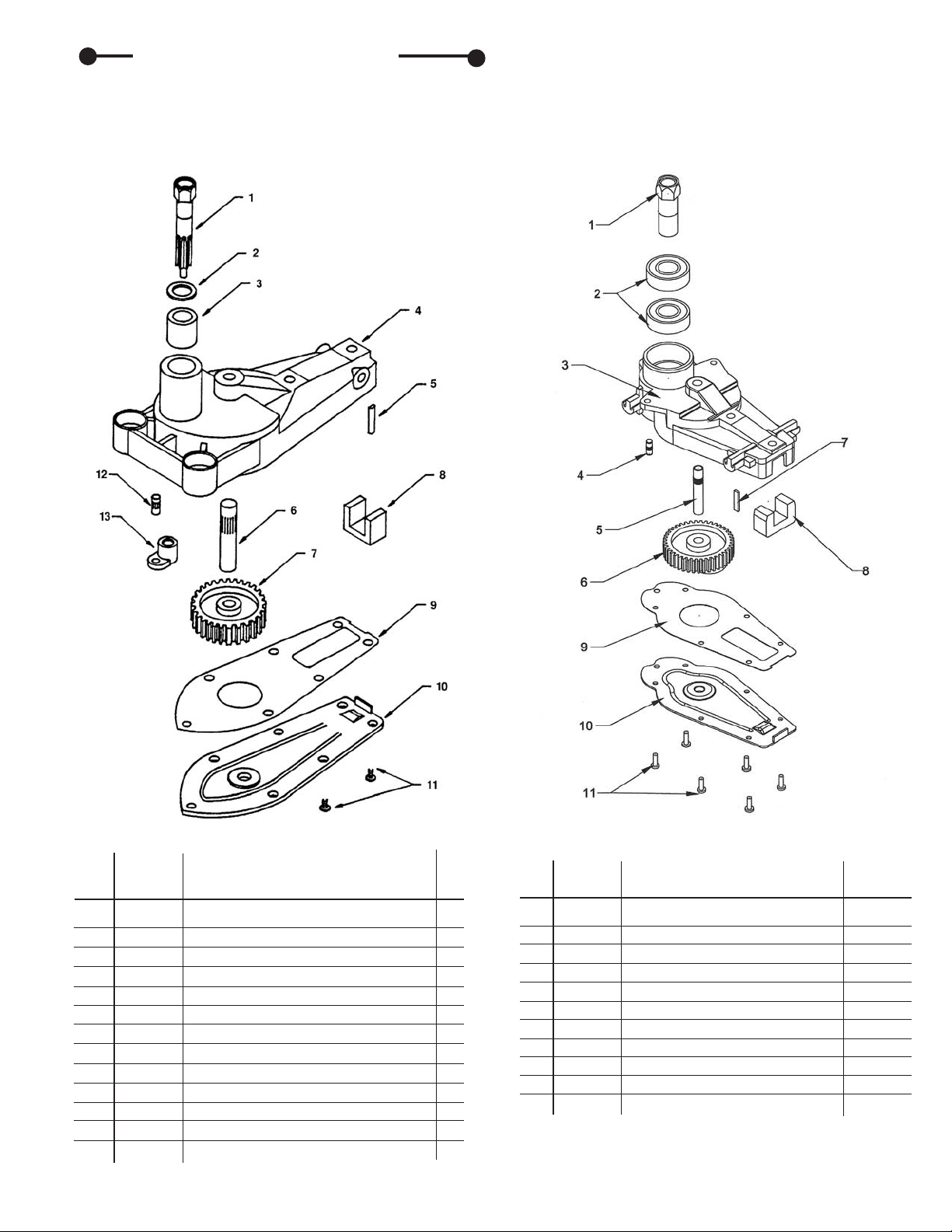
Parts Explosions
B. Gear Housing Assembly -
Double Edge Hedge Trimmer
Key
No. Part No. Description Qty.
1 320004 Pinion 1
2 320102 Bearing 2
3 320001 Gear Housing 1
4 16-80 Cover Plate Pin 1
5 16-61 Eccentric Shaft 1
6 320005 Eccentric Gear 1
7 D16-56F Wear Plate 1
8 314 Felt 1
9 320100 Gasket 1
10 320101 Cover Plate 1
11 16-81-1 6-32 x 5/16 Screw 6
A. Gear Housing Assembly -
Single Edge Hedge Trimmer
Key
No. Part No. Description Qty.
1 371 Pinion 1
2 375 Washer 1
3 374 Upper Bushing 1
4 300000
Gear Hsg Assem. (inc. Key No. 3, 6, 12
)1
5 D16-56F Wear Plate 1
6 16-61 Eccentric Shaft 1
7 372 Eccentric Gear 1
8 314 Felt 1
9 319 Gasket 1
10 316 Cover Plate 1
11 16-81 6-32 x 5/16 Screw Pack 1
12 16-80 Cover Plate Pin 1
13 373 Lower Bushing 1
Page 14

14
C. Cutting Bar and Side Handle Assembly - Single Edge Hedge Trimmer
Key
No. Part No. Description Qty.
1 300000 Gear Housing Assembly 1
216-54B 1/4-28 Whiz Flange Locknut (For Model 2230S) 7
216-54B 1/4-28 Whiz Flange Locknut (For Model 2242S) 9
3 300300 Frame Bar Brace 1
4 300200 Side Handle 1
5 300201 Grip 1
6 300310 30" Frame Bar (For Model 2230S) 1
6 300314 42" Frame Bar (For Model 2242S, Not Shown) 1
7 30-2 30" Inside Blade (For Model 2230S) 1
7 42-2 42" Inside Blade (For Model 2242S, Not Shown) 1
8 30-1 30" Outside Blade (For Model 2230S) 1
8 42-1 42" Outside Blade (For Model 2242S Not Shown) 1
9 16-93 Blade Guard (For Model 2230S) 5
9 16-93 Blade Guard (For Model 2242S) 7
10 16-54A Large Head Phillips Screw (For Model 2230S) 4
10 16-54A Large Head Phillips Screw (For Model 2242S) 6
11 300504 Large Head Screw 1/4-28 x 7/8 1
12 16-65 Connecting Rod Spacer 1
13 16-64 Connecting Rod 1
14 300316 Thread Protector (For Model 2230S) 2
15 3036-B 1/4-28 Flange Locknut 2
17 16-51B Drive Pin - Outside Blade 1
18 16-52B Drive Pin - Inside Blade 1
Page 15
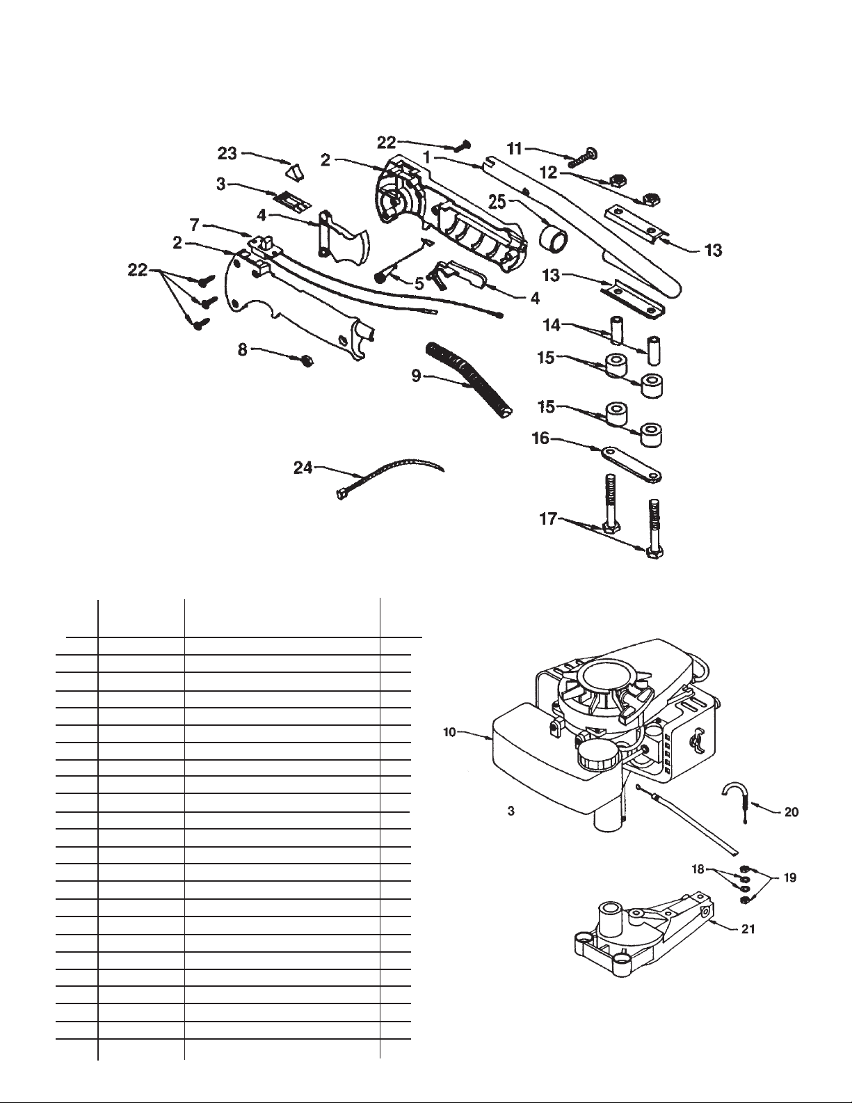
15
D. Engine and Rear Handle Assembly - Single Edge Hedge Trimmer
Key
No. Part No. Description Qty.
1 300101 Handle 1
2 300103 Grip (Set) 1
3 300117 Switch Plate 1
4 300122 Trigger Set 1
5 300108 Trigger \ Lockout Springs 1
7 300110 Switch/With Leads 1
8 973 10-32 Lock Nut 1
9 300116 Conduit 1
10 380E-4BHIE Engine 1
11 300503 10-32 x 1 1/4" Machine Screw 1
12 972 1/4-20 Lock Nut 2
13 300102 Handle Support Channel 1
14 300113 Spacer 2
15 300111 Shock Absorber 4
16 300112 Support Plate 1
17 300505 1/4-20 x 2 1/2" Bolt 2
18 4079 6MM Star Lock Washer 2
19 4078 6MM Nut 2
20 300115 Throttle Cable 1
21 300000 Gear Housing Assembly 1
22 300511 7/8" Phillips Pan Head Screw 4
23 300109 Switch Cap 1
24 300118 Cable Tie 1
25 376-1 Handle End Cap 1
Page 16
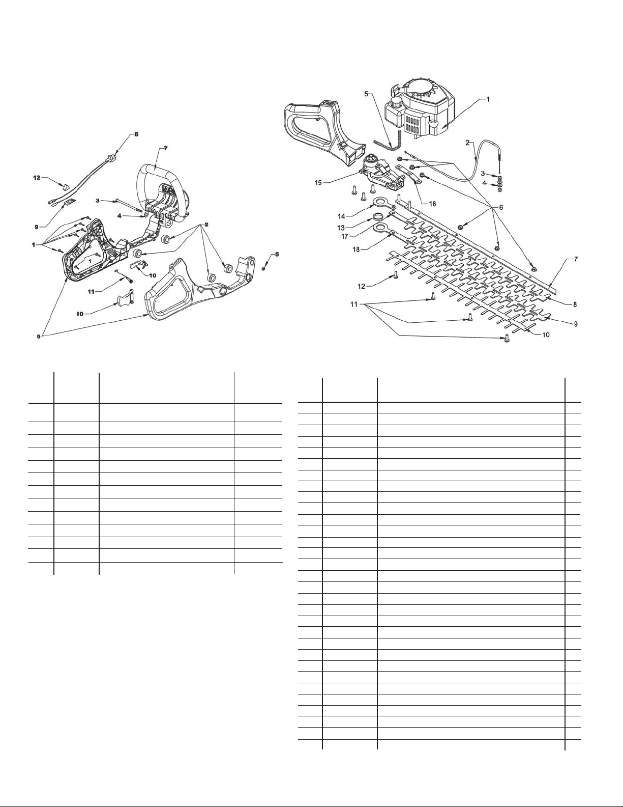
16
E. Handle Assembly -
Double Edge Hedge Trimmer
Key
No. Part No. Description Qty.
1 300511 7/8" Phillips Pan Head Screw 8
2 320403 Shock Absorber 4
3 320501 Bolt, 10-32 x 2 3/4 1
4 300508 #10 Flat Washer 1
5 973 10-32 Lock Nut 1
6 320400 Grip Handles Set 1
7 320404 Loop Handle with Guard 1
8 300120 Switch with Lead Wires 1
9 300117 Switch Plate 1
10 300122 Trigger Set 1
11 300108 Trigger/ Lockout Spring 1
12 300109 Switch Cap 1
13 300121 Terminal Eyelet Spade 1
F. Cutting Bar Assembly with Handle and
Engine - Double Edge Hedge
Trimmer
Key
No. Part No. Description Qty.
1 320900 Engine 1
2 300115 Throttle Cable 1
3 4078 6MM Nut 2
4 4079 M6 Washer 2
5 300119 Conduit 1
616-54B 1/4 - 28 Whiz Flange Locknut - Model 2130 7
Model 2124 6
Model 2119 5
7 320304 30" DBL Frame Bar w/Studs - Model 2130 1
7 320302 24" DBL Frame Bar w/Studs - Model 2124 1
7 320300 19" DBL Frame Bar w/Studs - Model 2219 1
8 30-2D 30" D.S. Inside Blade - Model 2130 1
8 24-2D 24" D.S. Inside Blade - Model 2124 1
8 19-2D 19" D.S. Inside Blade - Model 2119 1
9 30-1D 30" D.S. Outside Blade - Model 2130 1
9 24-1D 24" D.S. Outside Blade - Model 2124 1
9 19-1D 19" D.S. Outside Blade - Model 2119 1
10 30-42 30" Protective Comb - Model 2130 1
10 24-42 24" Protective Comb - Model 2124 1
10 19-42 19" Protective Comb - Model 2119 1
11 16-54A Large Head Phillips Screw - Model 2230D 4
Model 2224D 3
Model 2216D 2
12 300504 7/8" Large Head Phillips Screw 1
13 16-65 Connecting Rod Spacer 1
14 16-64 Connecting Rod 1
15 320000 Gear Housing Assembly 1
16 300300 Frame Bar Brace 1
17 16-52B Drive Pin Inside Blade 1
18 16-51B Drive Pin Outside Blade 1
19 320502 8-32 x 5/8” Phillips Screw 3
Page 17
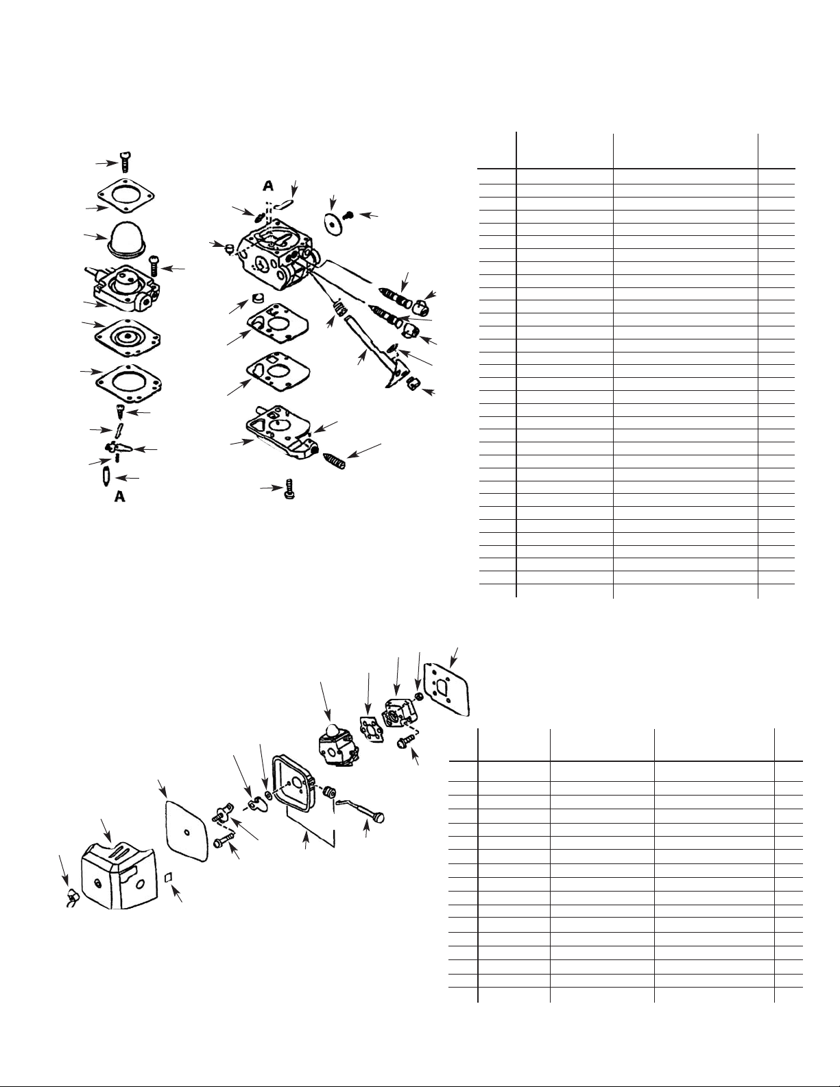
G. SV-4B (H2) Type IE Engine Parts Assembly - Double Edge
SV-4B (H) Type 1E Engine Parts Assembly - Single Edge
Key
No. Part No. Description Qty.
12520013123 Carburetor Assembly 1
1 1250013123 Screw 4
2 P005000620 Retainer 1
3 12538108660 Pump, Purge 1
4 12531005360 Screw 2
5 P005000600 Base, Purge` 1
6A B Diaphragm, Metering 1
7A B Gasket, Metering 1
8 12533942030 Screw 1
9A Pin, Metering Arm 1
10 A Lever, Metering 1
11 A Spring, Metering Lever 1
12 A Valve, Inlet Needle 1
13 A Plug, Welch 1
14 12531649030 Valve, Throttle 1
15 12531413930 Screw 1
16 12531813120 Needle, Low Speed 1
17 12532909860 Cap, Limiter L.S. 1
18 12532013310 Needle, High Speed 1
19 12532939030 Cap, Limiter H.S. 1
20 12532713930 Clip 1
21 12537242030 Swivel 1
22 12531713310 Shaft, Throttle 1
23 12531342030 Spring, Throttle Return 1
24 12537813310 Piece, Friction 1
25 12533306960 Spring, Idle Adjust 1
26 12531012820 Screw, Throttle 2
27 12532412820 Cover, Pump 1
28 A B Gasket, Fuel Pump 1
29 A B Diaphragm, Fuel Pump 1
30 A Strainer 1
31 12537613120 Nozzle, Main Check Valve 1
32 12532715130 Clip 1
Key
No. Part No. Description Remarks Qty.
1 13001042032 Gasket, Intake Included in kit 88900045131 1
2 90023805020 Screw 5 x 20 2
3 17851004560 Rod, Choke 1
4 13030104560 Case, Air Cleaner Includes Item 5 1
5 17881005230 Grommet 1
6 13041005360 Bracket, Air Cleaner 1
7 90024205057 Screw 5 x 57 2
8 89012140630 Label, Choke 1
9 90052800005 Nut, Wing 1
10 13032611522 Cover, Air Cleaner 1
11 13031004560 Filter, Air 1
12 17851504560 Shutter, Choke 1
13 17851600830 Spacer 1
14 12520013123 Carburetor, Asy. 1
15 13001642031 Gasket, Intake Included in kit 88900045131 1
16 13001742031 Insulator 1
17 90050000005 Nut 5 2
17
Carburetor
Air Filter with Carburetor
1
4
5
6
7
8
9
10
11
12
13
32
31
30
29
28
27
26
11
12
13
14
15
16
17
1
2
3
4
6
7
8
9
10
5
24
25
21
22
23
19
20
18
17
16
14
15
2
3
Page 18
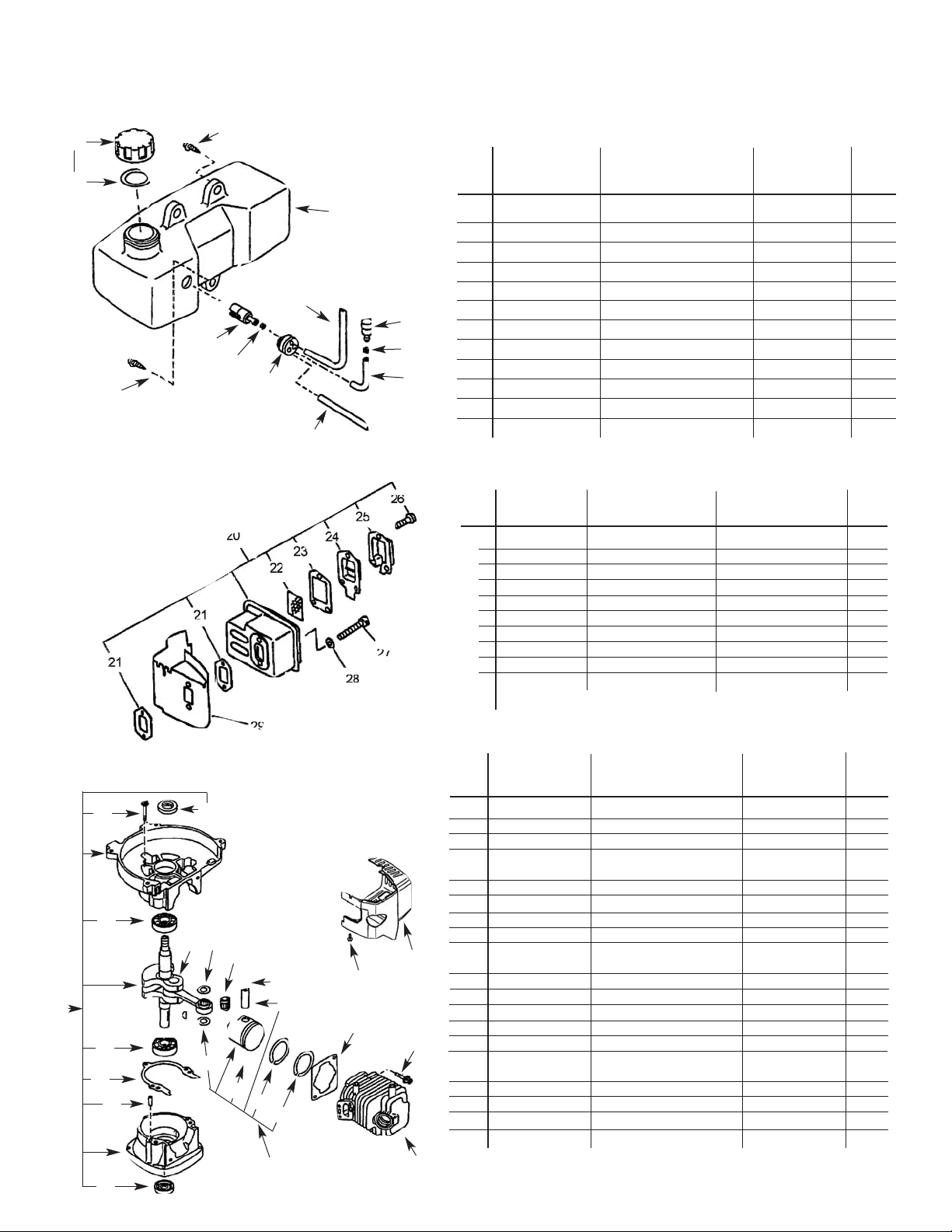
Key
No. Part No. Description Remarks Qty.
19 90027505015 Screw 5 x 15 3
20 13100511820 Tank, Fuel 1
21 13201011520 Pipe 3 x 5 x 210 1
22 13130040630 Valve, Check 1
23 13011100530 Clip, Pipe 1
24 131312244330 Pipe 3 x 5 x 70 1
25 13201049030 Pipe 3 x 6 x 50 1
26 13211546730 Grommet, Fuel 1
27 13201309820 Clip 1
28 13120507320 Strainer, Fuel 1
29 13100453530 Cap Asy., Fuel Tank
Includes item 30 1
30 131011655830 Gasket, Fuel Tank Cap 1
Key
No. Part No. Description Remarks Qty.
1 10020411520 Crankcase Kit
Includes items 2-6 1
2 10021242030 Seal, Oil 2
3 10021503930 Pin, Dowel 2
4 ----------------- Gasket, Crankcase Included in kit
88900045131 1
5 90081036201 Bearing, Ball 6201 2
6 90016205028 Bolt 5 x 28 3
7 10010012820 Crankshaft Asy. 1
8 61032502730 Key, Woodruff 1
9 10000006962 Piston, Kit Includes items
10-14 1
10 10001105330 Ring, Piston 2
11 10001504630 Circlip, Piston Pin 2
12 10001408960 Spacer, Piston Pin 2
13 10011305930 Bearing, Needle 1
14 10001311520 Pin, Piston 1
15 10101044332 Gasket, Cylinder Base Included in kit
88900045131 1
16 10101106561 Cylinder 1
17 90016205022 Bolt 5 x 22 2
18 90023804018 Screw 4 x 18 2
19 10150612821 Cover, Cylinder 1
G. SV-4B (H2) Type IE Engine Parts Assembly- Double Edge
SV-4B (H) Type 1E Engine Parts Assembly- Single Edge
Key
No. Part No. Description Remarks Qty.
20 14580011820 Muffler Asy.
Includes items 21-26
1
21 V104000160 Gasket, Muffler Included in kit 88900045131 2
22 14586240630 Screen, Muffler 1
23 14586642031 Gasket, Muffler Lid
Included in kit 88900045131 1
24 14587642030 Lid, Muffler 1
25 14586306960 Fixture Screen 1
26 90024204010 Screw 4 x 10 3
27 90010505050 Bolt 5 x 50 2
28 90000000005 Washer 5 2
29 14587105360 Cover, Muffler 1
18
Gas Tank
Muffler
Crankcase
19
29
30
19
21
22
23
24
25
16
15
18
19
17
11
13
12
7
9
26
27
28
20
11
10
10
12
14
5
1
4
3
2
5
6
2
Page 19
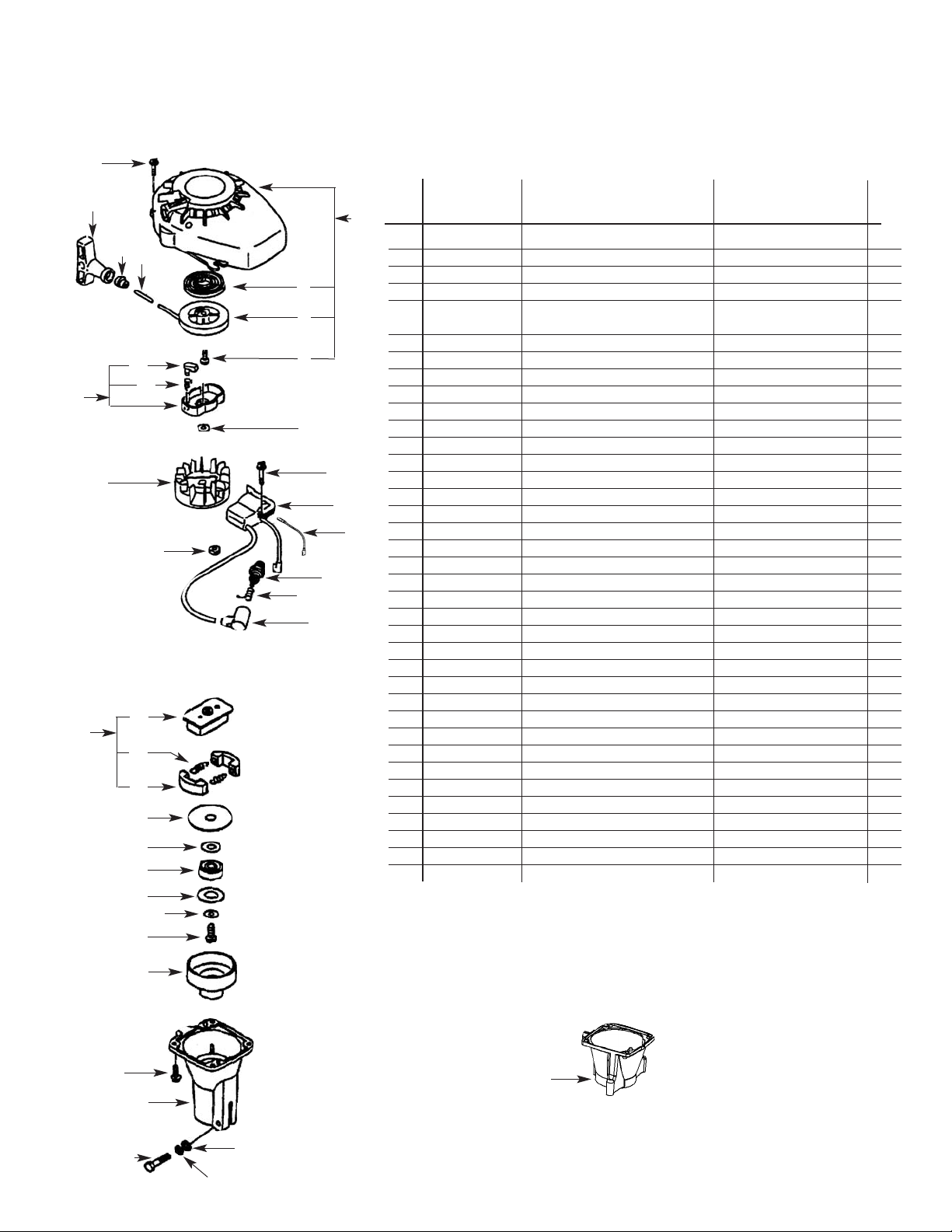
19
H. SV-4B (H2) Type IE Engine Parts Assembly- Double Edge
SV-4B (H2) Type IE Engine Parts Assembly - Single Edge
Single Edge Clutch Case
Double Edge Clutch Case
Key
No. Part No. Description Remarks Qty.
1 17720012820 Starter Asy. Includes items 2-7 1
2 17722042030 Spring, Rewind 1
3 17721544430 Drum, Starter 1
4 17723644330 Screw 1
5 ----------------- Rope. Starter
use bulk rope 99944400040 1
3.0 x 890 (.12 x 33.5)
6 17722742030 Guide, Rope 1
7 17722811120 Grip, Starter 1
8 90023804016 Screw 4 x 16 4
9 90060500008 Washer, Spring 8 1
10 90016204022 Bolt 4 x 22 2
11 15660152130 Coil, Ignition 1
12 99944500071 Spark Plug BPM-7Y 1
13 15901103432 Coil Spark Plug 1
14 15901201620 Cap, Spark Plug 1
15 15611004920 Bushing 1
16 15680105360 Flywheel Includes items 18, 19 1
17 17720212220 Pawl Asy., Starter 1
18 17723442030 Spring, Pawl Return 2
19 17721844330 Pawl, Return 1
20 90060000005 Washer 5 1
21 90060500005 Washer, Spring 5 1
22 90011505025 Bolt 5 x 25 1
23 90023804014 Screw 4 x 14 4
24 61022311520 Case, Clutch (Single Edge) 1
24a A570000050 Case, Clutch (Double Edge) 1
25 17501004633 Drum, Clutch 1
26 90023806012 Screw 6 x 12 1
27 17501411520 Washer, Clutch 1
28 17504404630 Washer, Clutch 1
29 90080836000 Bearing, Ball 6000 1
30 90060000010 Washer 10 1
31 17501904630 Plate, Clutch Includes items 33-35 1
32 17500007531 Clutch Asy. 1
33 17500905131 Shoe, Clutch 2
34 17501805130 Spring, Clutch 2
35 17501605020 Hub, Clutch 1
36 16202152830 Lead, Ignition 1
Starter, Ignition, and Clutch
3
4
19
18
17
2
5
6
7
8
1
9
10
11
36
12
13
14
35
33
31
30
29
28
27
25
24
24a
23
22
20
21
26
32
15
16
34
Page 20

This is additional detailed information about the EPA PHASE I and the
CALIFORNIA EMISSIONS DEFECT WARRANTY
for your utility
and/or lawn and garden equipment engine.
WHAT DOES THIS WARRANTY COVER?
The Manufacturer warrants that your unit was designed, built and
equipped to conform with applicable EPA Phase I/California emissions
standards and that your unit is free from defects in material and
workmanship that would cause it to fail to conform with applicable
requirements within two (2) years. The warranty period begins on the
date the product is delivered to a retail purchaser. This is your
emission control system, DEFECTS WARRANTY.
HOW WILL A COVERED PART BE CORRECTED?
If there is a defect in a part covered by this warranty, The
Manufacturer's Authorized Service Dealer will correct the defect.
You will not have to pay anything to have the part adjusted, repaired
or replaced. This includes any labor and diagnosis for warranted
repairs performed by the dealer. In addition, engine parts not expressly
covered under this warranty but whose failure is a result of a failure of
a covered part will be warranted.
Emissions System repairs covered under this warranty should be
completed in a reasonable time, not to exceed 30 days.
IMPORTANT
If the diagnosis reveals no defect, the emission defect
warranty does not apply.
WHAT PARTS ARE COVERED BY THE EPA PHASE I/CALIFORNIA
EMISSIONS DEFECT WARRANTY?
•Any emission related part not scheduled for, "required maintenance"
(See Engine Owner’s Manual, "SERVICE MAINTENANCE
SCHEDULE") will be repaired or replaced within the warranty
period. The repaired or replaced part will be warranted for the
remaining Emissions Defect warranty period.
• Any emission related part scheduled for replacement during
"required maintenance" (See Engine Owner’s Manual, "SERVICE
MAINTENANCE SCHEDULE") is warranted for the period of time
prior to the first scheduled replacement point for that part. Any
such part repaired or replaced under warranty shall be warranted
for the remainder of the period prior to the first scheduled
replacement point for that part.
• Any manufacturer-approved replacement part may be used in the
performance of any warranty maintenance or repairs on emissionrelated parts, and must be provided without charge if the part is still
under warranty.
•Any replacement part that is equivalent in performance and
durability may be used in non-warranty maintenance or repairs, and
shall not reduce the warranty obligations of the manufacturer.
•The owner is responsible for the performance of the required
maintenance described in the Owner’s manual.
SPECIFIC EMISSION RELATED WARRANTED PARTS:
Carburetor (complete assembly or replaceable components)
Air Filter
Electronic Ignition System
Spark Plug
WHAT IS NOT COVERED BY THE EMISSIONS DEFECT
WARRANTY?
• Any failure caused by abuse, neglect, improper maintenance.
• Any failure caused by unapproved modifications, use of unapproved
add-on parts/modified parts or unapproved accessories.
EPA Phase I; California Air Resources Board, and your Equipment
Manufacturer are pleased to explain the emission control system
warranty on your (year) utility or lawn and garden equipment engine.
New utility and lawn and garden equipment engines must be designed,
built and equipped to meet stringent EPA Phase I/California anti-smog
standards. Echo, Incorporated must warrant the emission control
system on your utility or lawn and garden equipment engine for the
periods of time listed below provided there has been no abuse, neglect
or improper maintenance of your utility or lawn and garden equipment
engine.
Your emission control system may include parts such as the carburetor
fuel system, and the ignition system. Also included may be hoses,
belts, connectors and other emission-related assemblies.
Where a warrantable condition exists, The Manufacturer will repair
your utility or lawn and garden equipment engine at no cost to you
including diagnosis, parts and labor.
MANUFACTURER'S WARRANTY COVERAGE:
The 1996 and later utility and lawn and garden equipment engines
are warranted for two years. If any emission-related part on your
engine is defective, the part will be repaired or replaced by The
Manufacturer.
OWNER'S WARRANTY RESPONSIBILITIES:
• As the utility or lawn and garden equipment engine owner, you are
responsible for the performance of the required maintenance listed in
your Owner’s Manual . The Manufacturer recommends that you
retain all receipts covering maintenance on your utility or lawn and
garden equipment engine, but The Manufacturer cannot deny
warranty solely for the lack of receipts or for your failure to ensure
the performance of all scheduled maintenance.
• As the utility or lawn and garden equipment engine owner, you
should however be aware that The Manufacturer may deny you
warranty coverage if your utility or lawn and garden equipment engine
or a part has failed due to abuse, neglect, improper maintenance or
unapproved modifications.
• You are responsible for presenting your utility or lawn and garden
equipment engine to an The Manufacturer authorized service center
as soon as a problem exists. The warranty repairs should be completed
in a reasonable amount of time, not to exceed 30 days.
If you have any questions regarding your warranty rights and
responsibilities, you should contact your Product Manufacturer.
20
Emissions Defect
Warranty Explanation
Emissions Control
Warranty Statement
Page 21

5 YEAR LIMITED SERVICE & WARRANTY POLICY
FOR GASOLINE HEDGE TRIMMERS
All Little Wonder Gasoline Hedge Trimmers are guaranteed against defects in
material and workmanship for a period of FIVE YEARS from date of purchase, when used
for RESIDENTIAL SERVICE, or COMMERCIAL SERVICE. Any Little Wonder
Gasoline Hedge Trimmer or part found to be defective within the warranty period is to
be returned to any registered Little Wonder Dealer.
Engines for all gasoline powered products are warranted separately by the engine
manufacture for a period of a year. Therefore, there are no warranties made, expressed
or implied, for engines for gasoline powered products by Little Wonder.
Transportation charges for parts and units submitted for replacement under this warranty
must be borne by the purchaser.
THIS WARRANTY shall not be effective if the product has been subject to misuse,
negligence or accident, used in cutting hedges or shrubs greater than 1" in diameter, used
to cut foreign objects such as wire, rocks, or fences, or if the product has been repaired
or altered outside of our Southampton factory in any respect which affects its condition
or operation.
Little Wonder shall not be liable for any special indirect or consequential damages
arising from defective equipment. Any implied warranty, including merchantability of
fitness for a particular purpose, shall not extend beyond the written warranty period.
THIS WARRANTY shall only be effective if the enclosed Warranty/Registration card is
properly filled out and returned to Little Wonder, Div. of Schiller-Pfeiffer, Inc. at
time of purchase.
21
Specifications, descriptions, and illustrative material in this literature are as accurate as known at the time of publication, but are subject to change without notice.
P/N 320702
02/02
LITTLE WONDER®
DIVISION OF SCHILLER-PFEIFFER, INCORPORATED
1028 STREET ROAD, P.O. BOX 38
SOUTHAMPTON, PA 18966
PHONE 877-596-6337 • FAX 215-357-8045
www.littlewonder.com
Page 22

Taille-haies à essence - Manuel de
l’utilisateur et
Consignes de sécurité
Page 23

Informations importantes
A. Introduction . . . . . . . . . . . . . . . . . . . . . . . . . . .23
B. Informations sur l’entretien . . . . . . . . . . . . . . .23
C. Informations particulières de sécurité . . . . . . .23
Sécurité et avertissements
A. Autocollants de sécurité . . . . . . . . . . . . . . . . .24
B. Consignes générales de sécurité . . . . . . . . . . .24
C. Avertissements – À ne pas faire . . . . . . . . . . .25
D. Avertissements — À faire . . . . . . . . . . . . . . . .23
E. Avertissements concernant le moteur et le
carburant — À ne pas faire . . . . . . . . . . . . . . .26
F. Avertissements concernant le moteur et le .
carburant — À faire . . . . . . . . . . . . . . . . . . . . .26
Consignes d’assemblage
A. Modèles à double tranchant . . . . . . . . . . . . . .26
B. Modèles à un seul tranchant . . . . . . . . . . . . .26
C. Méthode de rodage . . . . . . . . . . . . . . . . . . . . .27
Mode d’emploi
A. Mélange de carburant. . . . . . . . . . . . . . . . . . . .27
B. Mélange du carburant . . . . . . . . . . . . . . . . . . .27
C. Démarrage d’un moteur froid . . . . . . . . . . . . .28
D. Démarrage d’un moteur chaud . . . . . . . . . . . .28
E. Démarrage d’un moteur noyé . . . . . . . . . . . . .28
F. Mise à l’arrêt du moteur . . . . . . . . . . . . . . . .28
G. Coupe . . . . . . . . . . . . . . . . . . . . . . . . . . . . . . . .29
Entretien
A. Lubrification . . . . . . . . . . . . . . . . . . . . . . . . . . .29
B. Moteur . . . . . . . . . . . . . . . . . . . . . . . . . . . . . . .29
C. Entreposage à long terme (plus de 60 jours) .29
Réparations et réglages
A. Dépannage . . . . . . . . . . . . . . . . . . . . . . . . . . . .30
B. Spécifications du moteur . . . . . . . . . . . . . . . . .30
C. Guide d’entretien . . . . . . . . . . . . . . . . . . . . . . .31
D. B. Réglage des lames . . . . . . . . . . . . . . . . . . . .31
E. Réglage du carburateur . . . . . . . . . . . . . . . . . .32
Vues éclatées
A. Ensemble de carter d’engrenages –
Taille-haies à un seul tranchant . . . . . . . . . . .33
B. Ensemble de carter d’engrenages –
Taille haies à double tranchant . . . . . . . . . . . .33
C. Ensemble de barre de coupe et de poignée
latérale – Taille-haies à un seul tranchant . . .34
D. Ensemble de moteur et de poignée
arrière – taille-haies à un seul tranchant . . . . .35
E. Ensemble de poignée -- taille-haies à
double tranchant . . . . . . . . . . . . . . . . . . . . . . .36
F. Ensemble de barre de coupe, poignée
et moteur – taille-haies à double tranchant .36
G. Moteur - SV-4B (H) Type IE . . . . . . . . . . . . . .37
H. Moteur - SV-4B (H) Type IE –
démarreur, allumage, embrayage . . . . . . . . . . .39
Garantie . . . . . . . . . . . . . . . . . . . . . . . . . . .
40-41
A. Introduction
Au nom de tout le personnel de Little Wonder, nous
tenons à vous remercier de votre achat d’un taille-haies à
essence Little Wonder. Cet appareil de coupe
professionnel a été conçu en fonction des normes les plus
strictes afin de vous procurer de nombreuses heures
d’utilisation ininterrompue.
Ce manuel contient les informations nécessaire en vue d’une
utilisation et d’un entretien efficaces et sûrs. Pour votre
sécurité, il est extrêmement important que vous lisiez et
compreniez le manuel dans son intégralité avant d’utiliser
l’appareil.
B. Informations sur l’entretien
Barre de coupe
Contactez votre vendeur Little Wonder local.
Moteur
Contactez un vendeur Echo agréé. Vous trouverez une liste des
vendeurs dans les Pages jaunes sous les rubriques « Fournitures
de matériel de pelouses et jardins », « Entretien des pelouses »
ou « Tondeuses à gazon ».
C. Informations particulières de sécurité
AVERTISSEMENT - DANGER
ATTENTION : CE SYMBOLE SOULIGNE NOS
IMPORTANTES CONSIGNES DE SÉCURITÉ.
LORSQUE VOUS VOYEZ CE SYMBOLE,
SUIVEZ SON AVERTISSEMENT ! DEMEUREZ
VIGILANT !
Table des matières
Informations importantes
AVERTISSEMENT - DANGER
POUR RÉDUIRE LES RISQUES D’ACCIDENTS,
RESPECTEZ LES CONSIGNES DE SÉCURITÉ
CONTENUES DANS CE MANUEL.
L’INOBSERVANCE DE CES CONSIGNES PEUT
CAUSER DES BLESSURES GRAVES ET/OU DES
DOMMAGES CONSIDÉRABLES AUX
ÉQUIPEMENTS ET AUX BIENS.
AVERTISSEMENT - DANGER
L’ÉCHAPPEMENT DU MOTEUR DE CE PRODUIT
CONTIENT DES PRODUITS CHIMIQUES QUE
L’ÉTAT DE LA CALIFORNIE CONNAÎT COMME
CAUSANT LE CANCER, DES MALFORMATIONS
CONGÉNITALES OU AUTRES LÉSIONS DU
SYSTÈME REPRODUCTEUR.
Modèle
Double tranchant
Un seul tranchant
Poids à sec:
2119
x
11.7 lb.
2124
x
12.2 lb.
2130
x
12.9 lb.
2230S
x
12.25 lb.
2242S
x
13.25 lb.
Spécifications de poids
23
Page 24

A. Autocollants de sécurité
Une partie importante du système de sécurité incorporé dans
ce taille-haies consiste en autocollants d’avertissement et
d’information que l’on retrouve sur différentes pièces du taillehaies. Ces autocollants doivent être remplacés avec le temps en
raison d’abrasion, etc. Il vous incombe de remplacer ces
autocollants lorsqu’ils deviennent difficiles à lire. Leur
emplacement et leur numéro de référence pour la commande
sont indiqués ci-dessous.
B. Reglas generales de seguridad
1. CETTE MACHINE PEUT CAUSER DES BLESSURES
GRAVES. Lire attentivement les instructions sur la façon
appropriée de manier, de préparer, d’entretenir, ainsi que de
mettre en marche et à l’arrêt la machine. Il importe de se
familiariser avec toutes les commandes et l’utilisation
appropriée de la machine. Accordez une attention particulière à
toutes les sections relatives à la sécurité.
2. Gardez toujours une prise ferme sur les deux poignées
lorsque les lames bougent et/ou le moteur tourne. Dans le cas
d’un appareil à double tranchant, tenez la poignée annulaire
avant d’une main et la poignée arrière de l’autre. Dans le cas
d’un appareil à un seul tranchant, tenez la poignée avant de la
main droite et la poignée arrière de la main gauche. SOYEZ
VIGILANT ! Les lames continuent leur mouvement pendant un
moment après le relâchement de la gâchette de l’étrangleur ou
la mise à l’arrêt du moteur. Assurez-vous que les lames se sont
complètement arrêtées et que le moteur est arrêté avant de
relâcher une des poignées.
3. Maintenez une posture stable et un bon équilibre ; restez
d’aplomb pendant l’opération de coupe. Avant de commencer à
couper, vérifiez l'aire de travail pour y relever tout obstacle
susceptible de vous faire perdre votre posture, l'équilibre ou le
contrôle de la machine. Pendant que vous utilisez la machine,
assurez-vous toujours d’avoir une position de travail sûre,
surtout lorsque vous utilisez un escabeau ou une échelle.
4. Évitez de travailler en présence d’enfants, d’animaux
domestiques et de curieux.
5. Les lames continuent leur mouvement pendant un moment
après le relâchement de de la gâchette de l’obturateur ou la
mise à l’arrêt du moteur.
6. Mettez le moteur à l’arrêt avant de vérifier, d’entretenir ou
de travailler sur la machine.
7. Ne jamais utilisez sans les protecteurs, les poignées et les
dispositifs de sécurité en place.
8. Ne tentez jamais d’utiliser une machine incomplète ou une
machine ayant fait l’objet d’une modification non autorisée.
9. Pour réduire le risque d’incendie, gardez le moteur et le
silencieux exempts de débris, de feuilles ou de lubrifiant
excessif.
10. Sachez comment arrêter le moteur rapidement dans une
urgence.
AVERTISSEMENT - DANGER
UNE UTILISATION OU UN ENTRETIEN
INAPPROPRIÉ DE CE TAILLE-HAIES OU LE
DÉFAUT DE PORTER UNE PROTECTION
APPROPRIÉE PEUT PROVOQUER DES
BLESSURES GRAVES.
VEUILLEZ LIRE ET COMPRENDRE LES RÈGLES DE
FONCTIONNEMENT AINSI QUE TOUTES LES
INSTRUCTIONS DE CE MANUEL.
PORTEZ UN CASQUE ANTIBRUIT.
24
Sécurité et avertissements
AVERTISSEMENT - DANGER
SI LE TAILLE-HAIES EST UTILISÉ DE MANIÈRE
INAPPROPRIÉE OU SI LES PRÉCAUTIONS DE
SÉCURITÉ NE SONT PAS SUIVIES,
L’UTILISATEUR RISQUE DES BLESSURES
GRAVES À LUI-MÊME ET À AUTRUI.
ASSUREZ-VOUS DE LIRE ET DE COMPRENDRE
CE MANUEL AVANT DE TENTER D’UTILISER CE
TAILLE-HAIES.
ÉTIQUETTE DE
PROTECTION
AUTIVE/OCULAIRE NO.
DE RÉFÉRENCE 4036
ÉTIQUETTE
LITTLEWONDER NO.
DE RÉFÉRENCE 357
SILENCIEUX
GÂCHETTE DE
VERROUILLAGE
GÂCHETTE DE
L’ÉTRANGLEUR
POIGNÉE
ARRIÈRE
BOUCHON DU
RÉSERVOIR DE
CARBURANT
CARTER D’ENGRENAGES
ÉTIQUETTE D’AVERTISSEMENT –
NO. DE RÉFÉRENCE 300605
ÉTIQUETTE DE NO. DE MODÈLE
POIGNÉE AVANT
RÉGLAGE DE LA VIS ET
DU PROTÈGE-LAME
BARRE DE CADRE
POIGNÉE DU DÉMARREUR
FIL DE BOUGIE
CÂBLE DE L’ÉTRANGLEUR
BULBE D’AMORCE
PURIFICATEUR
D’AIR
BOUTON DU STARTER
LAMES DE
COUPE
SILENCIEUX
BOUCHON DU
RÉSERVOIR DE
CARBURANT
ÉTIQUETTE DU NO. DE
SÉRIE
POIGNÉE
ANNULAIRE
LAMES DE
COUPE
POIGNÉE DU DÉMARREUR
PURIFICATEUR D’AIR
CARTER D’ENGRENAGES
GÂCHETTE DE
L’ÉTRANGLEUR
POIGNÉE ARRIÈRE
INTERRUPTEUR D’ARRÊT
SYMBOLES
D’AVERTISSEMENT
BULBE D’AMORCE
FIL DE BOUGIE
INTERRUPTEUR
D’ARRÊT
AVERTISSEMENT
PORTER UN CASQUE ANTIBRUIT ET
DES LUNETTES DE PROTECTION.
IL IMPORTE DE LIRE ET DE BIEN
COMPRENDRE LE MANUEL DE
L’UTILISATEUR AVANT D’UTILISER
L’APPAREIL. GARDER EN LIEU SÛR.
RISQUE DE SE COUPER GARDER LES
DEUX MAINS SUR LES POIGNÉES ET
À L’ÉCART DES LAMES.
BARRE DE
CADRE
RÉGLAGE DE LA VIS
ET DE L’ÉCROU
PEIGNE DE SÉCURITÉ
BOUTON DU
STARTER
GÂCHETTE DE
VERROUILLAG
Page 25

25
C. Avertissements – À ne pas faire
N’utilisez pas le taille-haies d’une seule main, gardez les deux
mains sur les poignées avec les doigts et les pouces encerclant
les poignées pendant que les lames bougent et que le moteur
tourne.
Ne vous penchez pas de manière dangereuse et ne montez
pas sur des supports instables. Ne montez pas au sommet
d’une échelle pour effectuer une opération de coupe. Utilisez
le matériel adéquat pour atteindre des points élevés.
Conservez une bonne posture et un bon équilibre en toute
circonstance.
Ne saisissez jamais les lames de coupe.
N’utilisez jamais la machine avec un dispositif de coupe
endommagér ou excessivement usé.
Ne tentez jamais de dégager des branches coupées lorsque
les lames sont en mouvement ou que le moteur tourne.
N’essayez jamais de retirer un objet bloqué avant de mettre le
moteur à l’arrêt et de vous assurer que les lames sont
complètement arrêtées.
Ne neutralisez pas les dispositifs de sécurité.
Ne laissez pas les enfants ou les personnes non compétentes
utiliser cet appareil.
N'utilisez jamais ce taille-haies si vous êtes sous l'influence de
l'alcool ou de stupéfiants.
N’essayez pas de réparer ce taille-haies. Confiez les
réparations à un technicien ou revendeur qualifié. Assurez-vous
que seules des pièces Little Wonder d'origine sont
utilisées.
D. Avertissements — À faire
Prenez toujours le temps de lire et de respecter toutes les
consignes.
Soyez toujours vigilant. Regardez ce que vous faites et faites
preuve de discernement. N'utilisez pas l’appareil lorsque vous
êtes fatigué.
Habillez-vous toujours adéquatement. Ne portez pas de bijoux
ni de vêtements amples car ils pourraient être happés par les
pièces en mouvement. Portez des gants solides, antidérapants
et de taille adaptée. Les gants réduisent la transmission de
vibrations à vos mains. L’exposition prolongée aux vibrations
peut causer un engourdissement et d’autres problèmes. Portez
des chaussures antidérapantes pour assurer une posture
adéquate et sûre.
Portez toujours des lunettes de protection et un casque
antibruit. Les lunettes de protection doivent satisfaire à la
norme ANSI Z 87.1. Pour éviter les lésions auditives, nous
recommandons le port d'un casque antibruit lors de chaque
utilisation de l’appareil.
Tenez toujours l’appareil des deux mains lorsqu’il est en
fonctionnement. Vous pouvez vous blesser gravement en tenant
le taille-haies d’une seule main ou en le tenant mal.
Maintenez toujours les enfants, les animaux domestiques et les
personnes incompétentes à l’écart.
Utilisez toujours l’appareil correctement. Ne coupez que les
branches dont le type et la dimension sont décrits dans la
section Coupe de ce manuel. La surcharge ou l’utilisation
abusive de ce taille-haies peut causer sa défaillance prématurée
et des blessures. Faites preuve de bons sens.
Conservez toujours une distance sûre entre vous et les autres
personnes lorsque vous ne travaillez pas seul.
Inspectez toujours l’appareil avant chaque usage et assurezvous que toutes les poignées, les protections, les dispositifs de
sécurité et les attaches sont bien fixés, en état de marche et en
place.
Entretenez et examinez toujours l’appareil avec soin. Suivez les
instructions d’entretien données dans le manuel.
Rangez toujours le taille-haies à l'abri (dans un endroit sec) et
là où les enfants n'ont pas accès. Le taille-haies ainsi que le
carburant ne doivent pas être rangés dans la maison.
Soyez toujours au courant de ce qui vous entoure et
demeurez à l’affût de risques éventuels que vous ne pouvez pas
entendre en raison du bruit de la machine.
Posez toujours le protecteur du dispositif de coupe lorsque
vous transportez ou entreposez la machine.
AVERTISSEMENT - DANGER
SI LE TAILLE-HAIES EST UTILISÉ DE MANIÈRE
INAPPROPRIÉE OU SI LES PRÉCAUTIONS DE
SÉCURITÉ NE SONT PAS SUIVIES,
L’UTILISATEUR RISQUE DES BLESSURES GRAVES
À LUI-MÊME ET À AUTRUI.
ASSUREZ-VOUS DE LIRE ET DE COMPRENDRE CE
MANUEL AVANT DE TENTER D’UTILISER CE
TAILLE-HAIES.
AVERTISSEMENT - DANGER
MANIEZ LE CARBURANT AVEC SOIN. IL EST TRÈS
INFLAMMABLE. LE REMPLISSAGE EN
CARBURANT D’UN MOTEUR CHAUD OU À
PROXIMITÉ D’UNE SOURCE D’INFLAMMATION
PEUT PROVOQUER UN INCENDIE ET CAUSER
DES BLESSURES GRAVES ET/OU DES DOMMAGES
MATÉRIELS CONSIDÉRABLES.
Page 26

E. Avertissements concernant le moteur
et le carburant - À ne pas faire
Ne faites pas le plein de carburant et ne vérifiez pas le
carburant en fumant, à proximité d’une flamme nue ou autre
source d’inflammation. Arrêtez le moteur et assurez-vous qu’il
est froid avant de refaire le plein.
Ne laissez pas le moteur en marche pendant que le taillehaies est sans surveillance. Arrêtez le moteur avant de poser le
taille-haies ou de le transporter d’un endroit à un autre.
Ne mettez pas ce taille-haies en marche et ne l’utilisez pas à
l’intérieur ou dans un endroit mal aéré car du gaz de monoxyde
de carbone et autres gaz toxiques sont émis.
Ne faites pas tourner le moteur lorsque le système électrique
provoque une étincelle à l'extérieur du cylindre. Durant les
vérifications périodiques de la bougie, tenez la bougie à une
distance sûre du cylindre pour éviter de brûler le carburant
évaporé du cylindre.
Ne vérifiez pas la formation d’étincelles avec la bougie ou le
fil de bougie enlevé et mis à la terre. Utilisez un dispositif d’essai
homologué. Les étincelles peuvent enflammer les gaz.
Ne faites pas démarrer le moteur avec la bougie déposée. Si
le moteur est noyé, ouvrez l’étrangleur (enfoncez le bouton de
l’étrangleur) et tirez le recul jusqu’à ce que le moteur se mette
en marche. Si ceci échoue, lisez et suivez la section IV. E. de ce
manuel.
Ne faites pas tourner le moteur s'il y a une odeur d'essence
ou s'il existe d'autres conditions explosives.
N'utilisez pas l’appareil si de l'essence a été déversée.
Nettoyez complètement l'essence déversée avant de mettre le
moteur en marche.
Ne faites pas le plein de carburant à l'intérieur ou dans un
endroit mal aéré.
N'utilisez pas le taille-haies en cas d'accumulation de débris
autour du silencieux et des ailettes de refroidissement.
Ne touchez pas aux silencieux, cylindres ou ailettes de
refroidissement chauds car le contact peut causer des brûlures
graves.
F. Avertissements concernant le moteur
et le carburant - À faire
Utilisez toujours de l'essence fraîche dans le mélange de
carburant. De l'essence viciée peut causer des fuites.
Tirez toujours le cordon du démarreur lentement jusqu'à ce
qu'une résistance se fasse sentir. Tirez ensuite le cordon
rapidement pour éviter les rebonds et prévenir des blessures au
bras ou à la main.
Faites toujours marcher le moteur avec un pare-étincelles
installé et en bon état de marche. L’utilisation de silencieux de
pare-étincelles est requise par la loi de l’État de la Californie
(article 4442 du Code des ressources publiques de la
Californie), ainsi que dans d’autres états ou municipalités. La loi
fédérale américaine s’applique sur les terres fédérales.
Ce système d’allumage par étincelle satisfait toutes les exigences
des règlements canadiens sur le
matériel causant des
interférences.
Maniez toujours le carburant
avec soin ; il est très
inflammable. N’ajoutez jamais de
carburant à une machine dont le
moteur est chaud ou en
marche. N’inhalez pas les gaz de
carburant car ils sont toxiques.
Le taille-haies Little Wonder a été assemblé pour vous à
l’usine. Avant de le faire fonctionner, assurez-vous que toutes
les attaches sont bien serrées et que tous les protecteurs et les
dispositifs de sécurité sont en place et fonctionnent
correctement.
A. Modèles à double tranchant
Si le moteur doit être remis en place :
1. Poser le moteur en alignant d’abord l’entraînement
hexagonal du carter d’engrenages du taille-haies sur la douille
hexagonale du tambour d’embrayage du moteur.
2. Faites glisser le moteur auquel est fixé l’adaptateur de
moteur par-dessus la tige du carter d’engrenages jusqu’à ce qu’il
soit calé à fond sur le carter d’engrenages.
3. Aligner les trois trous filetés de l’adaptateur de moteur
sur les trous de montage du carter d’engrenages.
4. Utiliser trois vis 8-32 x 5/8 auxquelles sont fixées les
rondelles à ressort à doubler action. Voir Figure 1.
5. Relâcher la gâchette de l’obturateur et s’assurer que
l’obturateur revient à la position de ralenti, lorsque le levier du
carburateur repose sur la vis de ralenti. Le mouvement de
l’obturateur doit être doux et non gêné.
B. Modèles à un seul tranchant
1. Retirer l’ensemble de barre de coupe, le moteur avec l’ensemble de
poignée et d’obturateur, la poignée latérale et le sac de ferrures de
montage de leurs boîtes.
N˚ de pièce Description Qté.
972 Contre-écrou 1/4-20 2
300102 Rainure de support de poignée 2
300113 Tube d’espacement 2
300111 Amortisseur 4
300112 Plaque de support 1
300505 2/4-20 x 21 1/2 2
3036-B Contre-écrou à bride 1/4-28 2
26
Consignes d’assemblage
AVERTISSEMENT - DANGER
LES LAMES SONT EXTRÊMEMENT COUPANTES.
POUR ÉVITER DE SE BLESSER PENDANT LE
DÉBALLAGE DU TAILLE-HAIES, NE PAS LE SAISIR
PAR LES LAMES.
AVERTISSEMENT - DANGER
UN ASSEMBLAGE INAPPROPRIÉ DE CE TAILLE-
HAIES PEUT PROVOQUER DES BLESSURES
GRAVES. ASSUREZ-VOUS DE SUIVRE TOUTES LES
CONSIGNES SOIGNEUSEMENT.
POUR TOUTE QUESTION, CONTACTEZ VOTRE
VENDEUR LOCAL OU NOTRE USINE AU (215) 357-
5110.
Figure 1
Page 27

27
Fonctionnement
2. Placer la poignée avant par-dessus les deux goujons de 1/4-28
faisant saillie depuis la barre de cadre devant le carter d’engrenages. La
prise de la poignée doit être dirigée en sens opposé aux lames, comme
illustré (Figure 1). Sur le modèle 2230S, utiliser la série de goujons qui
place la poignée dans la position la plus confortable pour vous. Placer
les protecteurs de filet par-dessus la série de goujons qu’on choisit de
ne pas utiliser à ce stade pour protéger les filets. Fixer la poignée en
place à l’aide de deux contre-écrous à bride de 1/4-28 fournis. Les
écrous doivent être suffisamment serrés pour empêcher la poignée de
bouger mais pas trop serrés pour écraser le plastique.
Si le moteur doit être remis en place :
1. Poser le moteur en alignant d’abord l’entraînement hexagonal
du carter d’engrenages du taille-haies sur la douille hexagonale à un seul
côté du moteur.
2. Faire glisser le moteur par-dessus la tige de 1 po (2,5 cm) de
diamètre contenant l’entraînement hexagonal sur le carter d’engrenages
jusqu’à ce qu’il soit calé à fond sur le carter d’engrenages. Serrer la vis à
tête cylindrique à dépouille et empreinte cruciforme de 7/8 po (Pg. 30,
Key No. 22).
3. Presser les amortisseurs dans les douilles du carter
d’engrenages, suivis des tubes d’espacement. Fixer la rainure de support
de poignée et de tubulure, l’entretoise et le support à l’aide des contreécrous et boulons hexagonaux de 1/4-20 fournis.
4. Avec l’interrupteur d’arrêt en position d’arrêt et le moteur qui
ne tourne pas, s’assurer que l’étrangleur fonctionne adéquatement.
Saisir la poignée arrière de la main gauche en appuyant sur la gâchette
de verrouillage jusqu’à ce qu’elle s’arrête lorsque le levier du
carburateur touche le carter du carburateur. Relâcher la gâchette de
l’obturateur et s’assurer que l’obturateur revient à la position de ralenti
lorsque le levier du carburateur repose sur la vis de ralenti. Le
mouvement de l’obturateur doit être doux et non gêné.
C. Méthode de rodage
Il n’y a aucune exigence particulière pour le rodage du moteur. Après
un fonctionnement normal et deux (2) réservoirs de carburant, le
rodage du moteur est terminé.
Si des réglages sont nécessaires, suivre les Méthodes spéciales de
réglage du carburateur sur cette fiche technique supplémentaire. Tous
les autres réglages et les méthodes d’entretien sont décrits dans le
Manuel de l’utilisateur.
A. Mélange de carburant.
Votre taille-haies à un seul tranchant Little Wonder possède un
moteur à injection Echo modèle SV-4B(H), et le taille-haies à
double tranchant possède un moteur à injection Echo modèle
SV-4B(H2). Les deux modèles comportent des moteurs
refroidis par air à deux temps qui nécessitent un mélange
d’essence et d’huile de lubrification.
1. Informations importantes sur le moteur
Cet appareil est homologué en vue de son fonctionnement sur du
carburant deux temps approuvé (un mélange d’huile deux temps et
d’essence/de gasohol).
2. Énoncé concernant le carburant
Essence – Utiliser de l’essence avec indice d’octane de 89 [R+M/2]
ou du gasohol connu comme étant de bonne qualité. Le gasohol peut
contenir jusqu’à 10 % d’éthanol (alcool éthylique) ou 15 % de MTBE
(éther butylique tertiaire de méthyle). Le gasohol contenant du
méthanol (alcool de bois) N’est PAS approuvé.
3. Huile deux temps
Une huile à moteur deux temps satisfaisant la norme ISO-L-EGD
proposée (ISO/CD 13738) doit être utilisée. L’huile LW Premium 50:1
satisfait cette norme proposée. Les problèmes de moteur attribuables
à une lubrification inadéquate en raison de la non-utilisation d’une
huile conforme à la norme ISO-L-EGD, telle que l’huile deux temps
LW Premium 50:1, annuleront la garantie du moteur deux
temps. (Les pièces liées aux émissions sont couvertes pendant deux
ans seulement, quelle que soit l’huile deux temps employée,
conformément à l’énoncé précisé dans l’Explication de la garantie des
défauts d’émission EPA Phase 1/Californie.)
B. Mélange du carburant
1. Verser la moitié de l’essence dans un récipient sûr. NE PAS
mélanger le carburant dans le réservoir à carburant du moteur.
2. Ajouter l’huile à l’essence et mélanger.
3. Ajouter le reste de l’essence et mélanger à nouveau.
4. Poser le bouchon et essuyer l’essence déversée sur le récipient et
dans la zone.
5. Important : Le carburant deux temps se sépare et vieillit. Ne
pas mélanger plus que la quantité qui sera utilisée en un mois. Agiter
le récipient de carburant pour mélanger soigneusement le carburant
avant chaque usage. Ne pas tenter de faire marcher le moteur à
l’essence seulement, utiliser le mélange approprié de carburant.
AVERTISSEMENT - DANGER
L’UTILISATEUR DE CE TAILLE-HAIES EST
RESPONSABLE DES ACCIDENTS OU DES
DANGERS À LUI-MÊME, AUX AUTRES PERSONNES
OU À LEURS BIENS.
AVERTISSEMENT - DANGER
LE CARBURANT EST EXTRÊMEMENT
INFLAMMABLE. ON DOIT LE MANIER AVEC SOIN.
TENEZ-LE LOIN DES SOURCES D’INFLAMMATION.
NE FUMEZ PAS EN FAISANT LE PLEIN DE VOTRE
ÉQUIPEMENT.
Figure 1
Figure 2
VIS DU FIL DE TERRE
PROTECTEUR DE FILET
POIGNÉE
AVANT
EN SENS
OPPOSÉ AUX
LAMES
RAINURE DE SUPPORT
DE POIGNÉE
TUBE D’ESPACEMENT
AMORTISSEUR
DOUILLES
AMORTISSEUR
SUPPORT
LAMES DE
COUPE
Page 28

C. Démarrage d’un moteur froid
Le taille-haies possède un interrupteur d’allumage marche/arrêt
qui doit être utilisé pour mettre le moteur en marche et à
l’arrêt.
1. Placer le taille-haies à plat sur le sol ou une autre surface
stable. Faire glisser l’interrupteur d’allumage à la position de
marche (START).
2. Tirer le bouton du starter vers l’extérieur à la position
(fermée) de démarrage à froid (COLD START).
3. Pousser le bulbe d’amorce trois ou quatre fois ou jusqu’à
ce que le carburant soit visible dans la conduite transparente
de retour de carburant.
4. Tirer le cordon du démarreur jusqu’à ce que le moteur ait
des ratés. Tirer le cordon du démarreur en utilisant des
mouvements courts, de la moitié aux deux tiers de la longueur
du cordon.
5. Enfoncer le bouton du starter à la position RUN.
6. Remettre le moteur en marche et le laisser se réchauffer
pendant 2 à 3 minutes.
7. Les deux mains étant sur les poignées, presser
graduellement la gâchette de l’étrangleur pour augmenter la
vitesse et engager les lames.
REMARQUE. – Laisser le moteur se réchauffer pendant 2 à 3
minutes avant usage. L’omission de la période de réchauffement
causera des dommages au moteur.
D. Démarrage d’un moteur chaud
1. Faire glisser l’interrupteur d’allumage à la position de
marche (START).
2. Enfoncer le bouton du starter jusqu’à la position (ouverte)
RUN.
3. S’il n’y a pas de carburant dans la conduite transparente de
retour, appuyer sur le bulbe d’amorce 3 ou 4 fois ou jusqu’à ce
que du carburant soit visible dans la conduite.
4. Tirer le cordon du démarreur en utilisant des mouvements
courts, de la moitié aux deux tiers de la longueur du cordon.
5. Si le moteur ne se met pas en marche en 4 coups, suivre la
procédure de démarrage d’un moteur froid.
6. Les deux mains étant sur les poignées, presser
graduellement la gâchette de l’étrangleur pour augmenter la
vitesse du moteur et engager les lames.
E. Démarrage d’un moteur noyé
1. Retirer le bouchon de la bougie et dévisser la bougie à
l’aide d’une clé à bougies. Si l’extrémité de la bougie est
mouillée, il se peut que le moteur soit noyé.
2. Utiliser un papier essuie-mains ou un chiffon propre pour
sécher l’extrémité de la bougie.
3. Remettre la bougie et le bouchon en place.
4. Enfoncer le bouton du starter (position ouverte) et tirer le
cordon du démarreur trois ou quatre fois.
5. Tirer maintenant le bouton du starter vers l’extérieur
(position fermée) et tirer le cordon du démarreur jusqu’à ce
que le moteur ait des ratés.
6. Enfin, enfoncer le bouton du starter (position ouverte) et
tirer le cordon du démarreur pour mettre le moteur en
marche
F. Mise à l’arrêt du moteur
1. Relâcher la gâchette de l’étrangleur et laisser le moteur
revenir au ralenti.
2. Faire glisser l’interrupteur d’allumage à la position d’arrêt
(STOP).
3. S’assurer que les lames se sont complètement arrêtées
avant de relâcher l’une ou l’autre poignée.
28
Taille-haies à un seul
tranchant
Taille-haies à double
tranchant
AVERTISSEMENT - DANGER
ÉVITER D’ENGAGER LA LAME PAR ACCIDENT.
NE PAS PRESSER LA GÂCHETTE AU DÉMARRAGE.
MAINTENIR UN RÉGLAGE APPROPRIÉ DE RALENTI
DU MOTEUR (2500 À 2700 TR/MIN)
LA VITESSE MAX. DU MOTEUR EST
10 500 À 11 000 TR/MIN
AVERTISSEMENT - DANGER
SI LE MOTEUR NE S’ARRÊTE PAS LORSQUE
L’INTERRUPTEUR EST PLACÉ À LA POSITION
D’ARRÊT, RELÂCHER LA GÂCHETTE DE
L’ÉTRANGLEUR ET LAISSER LE MOTEUR
REVENIR AU RALENTI.
DÉPOSER LE TAILLE-HAIES, ET TIRER LE BOUTON
DU STARTER VERS L’EXTÉRIEUR, À LA POSITION
(FERMÉE) DE DÉMARRAGE À FROID.
POSITION DE
MARCHE
POSITION D’ARRÊT
INTERRUPTEUR
D’ALLUMAGE
POSITION DE
MARCHE
POSITION
D’ARRÊT
INTERRUPTEUR
D’ALLUMAGE
Rapide
Appuyer sur la détente
pour augmenter la vitesse
Verrouillé
Déverrouillé
Lent
Gâchette de
verrouillage
Gâchette de l’étrangleur
Page 29

29
G. Coupe
1. AVERTISSEMENT - Il importe de lire et de suivre
toutes les consignes de sécurité du manuel avant de tenter
d’utiliser ce taille-haies.
2. Ne pas mettre le moteur en marche avant d’avoir pris une
connaissance générale du taille-haies et d’en connaître toutes
les commandes et les fonctions.
3. Une fois le moteur en marche, saisir les poignées
fermement, la main gauche doit saisir la poignée arrière et la
main droite doit saisir la poignée avant sur les taille-haies à un
seul tranchant. Dans le cas d’un appareil à double tranchant,
tenir la poignée annulaire avant d’une main et la poignée arrière
de l’autre.
4. Presser l’étrangleur pour accélérer le moteur et engager les
lames.
5. Incliner le taille-haies de telle sorte que les dents de coupe
soient inclinées légèrement vers la haie ou le buisson à couper
et commencer l’opération de coupe. Utiliser un mouvement de
balayage à recouvrement en éloignant l’appareil de votre corps
pour obtenir une coupe égale et sans danger.
6. Cet appareil est conçu de manière à couper tout type de
haie ou de buisson ; cependant,
L’ÉPAISSEUR DE LA COUPE NE DOIT PAS
DÉPASSER UN POUCE (2,5 cm) DE DIAMÈTRE.
Une utilisation erronée de ce taille-haies annulera sa
garantie, en particulier, la coupe de haies ou
d’arbustes dont le diamètre des branches dépasse
un pouce (2,5 cm) ou la coupe d’objets étrangers
tels un fil métallique, un caillou ou une clôture.
Avant d’effectuer la coupe, vérifier l’absence sur
l’aire de travail d’objets étrangers tels que fils
métalliques, cordes, verre, clôtures et cailloux. Veiller à
éliminer tout objet étranger de l’aire de travail. Un manque
d’entretien correct annule la garantie de ce taille-haies.
A. Lubrification
1. Environ toutes les quatre heures d’utilisation normale, placer
quelques gouttes d’une huile légère (no 10) sur le bord arrière de
chaque protège-lame, au niveau de chaque vis de réglage.
2. Pour éviter les incidents, il est nécessaire de maintenir les
lames lubrifiées et propres. La sève qui s’accumule sur les lames peut
être enlevée à l’aide d’un mélange 50-50 de kérosène et d’huile no 10.
Les produits à base de pétrole pouvant diminuer la durée de vie de
certains plastiques, il est nécessaire d’enlever l’excédent du mélange
huile-kérosène se trouvant sur les pièces en matière plastique.
3. Au cours du remplacement des lames ou chaque fois que la
plaque inférieure du carter est enlevée, vérifier que la quantité de
graisse présente est correcte (environ au trois-quart plein dans la zone
des engrenages) et utiliser un nouveau joint (nº de pièce 319) pour
assurer une bonne assise de la plaque de carter. Vérifier et rectifier le
niveau de graisse après environ 50 heures d’utilisation. N’utiliser que
de la graisse Lubrico M3-3K9K (no de pièce. 16-78A) dans le carter
d’engrenages.
B. Moteur
1. Filtre à air
a. Nettoyer le filtre à
air avant chaque usage. Déposer
l’écrou à oreilles et le capot du
filtre.
b Si le filtre est
excessivement sale ou ne fait plus
bien, on doit le remplacer.
c Remettre le filtre en place à l’intérieur du couvercle en
s’assurant qu’il est bien calé.
d Remettre le couvercle en place sur le boîtier du
purificateur d’air et fixer à l’aide d’un écrou à oreilles.
2. Ailettes de refroidissement
Enlever la saleté et les débris autour des ailettes de
refroidissement et de l’échappement avant chaque usage. Une
circulation d’air appropriée est essentielle aux prestations et à la durée
du moteur.
C.
Entreposage à long terme (plus de 60 jours)
1. Le taille-haies doit être rangé dans un endroit sec et exempt
de poussière, hors de la portée des enfants.
2. Faire glisser l’interrupteur d’allumage à la position d’arrêt
(STOP).
3. Nettoyer le moteur et les lames soigneusement et enduire les
lames d’huile nº 10 pour prévenir la rouille.
4. Effectuer toutes les interventions requises d’entretien et de
services décrites dans le présent manuel.
5. Vidanger le réservoir de carburant et tirer le cordon du
démarreur plusieurs fois afin de retirer le carburant du carburateur.
6. Retirer la bougie et verser 1/4 d’once (7 ml) d’huile à moteur
deux temps propre et fraîche dans le cylindre à travers le trou de
bougie. Recouvrir le trou d’un chiffon et tirer le cordon du démarreur
deux ou trois fois.
7. Tout en regardant à travers le trou de la bougie, tirer le
cordon du démarreur jusqu’à ce que le piston atteigne le sommet de
sa course et arrêter.
8. Poser la bougie, mais laisser le câble d’allumage débranché.
AVERTISSEMENT - DANGER
LES LAMES CONTINUENT LEUR MOUVEMENT
PENDANT UN MOMENT APRÈS RELÂCHE DE
L’ÉTRANGLEUR OU MISE À L’ARRÊT DU MOTEUR.
MAINTENIR UNE PRISE FERME AVEC LES DEUX
MAINS PENDANT QUE LES LAMES SONT EN
MOUVEMENT ET/OU QUE LE MOTEUR TOURNE.
NE PAS MONTER AU SOMMET D’UNE ÉCHELLE POUR
EFFECTUER UNE OPÉRATION DE COUPE.
VÉRIFIER QUE L’ÉCHELLE OU TOUT AUTRE
SUPPORT UTILISÉ EST STABLE ET REPOSE SUR UN
SOL FERME.
MAINTENIR UNE BONNE POSTURE. RESTER
D’APLOMB.
SI UN BOURRAGE SE PRODUIT DANS LE TAILLE-
HAIES, RELÂCHER L’ÉTRANGLEUR ET METTRE LE
MOTEUR À L’ARRÊT. S’ASSURER QUE LES LAMES SE
SONT COMPLÈTEMENT ARRÊTÉES AVANT
D’ENLEVER L’OBSTRUCTION.
2,5 cm de
diamètre
Entretien
AVERTISSEMENT - DANGER
NE PAS RANGER LÀ OÙ LES GAZ DE CARBURANTA
PEUVENT S’ACCUMULER ET ATTEINDRE UNE
FLAMME OU UNE ÉTINCELLE.
FILTRE À AIR
Page 30

30
B. Spécifications du moteur
Poids à sec: 2,5 kg
Type de moteur: Moteur à essence deux temps, un seul
cylindre, refroidi par air
Rotation En sens anti-horaire, comme vu depuis le
DESSUS
Alésage 32,2 mm
Course 26,0 mm
Bougie NGK BPM7Y, Champion RCJ-7Y ou RCJ-8Y
L’écartement des bougies est de 0,65 mm
(0,026 po). Se reporter au Manuel de
l’utilisateur pourconnaître la procédure de
service
Carburant Carburant prémélangé deux-temps
Rapport carburant-huile Rapport de 50:1 avec huile ECHO ou
Little Wonder
Essence Sans plomb, indice d’octane de 89 ou
plus
Cylindrée 21,2 cc
Système d’échappement Silencieux pare-étincelles
Carburateur Modèle à diaphragme ZAMA de type
C1U tr/min au ralenti 2800 +- 250
tr/min
Système d’allumage Aucun réglage n’est requis pour
l’allumage
Réparations et réglages
Problème
1. Les lames ne
coupent pas de
manière nette.
2. Les lames ne
bougent pas lorsque
l’on appuie sur
l’obturateur.
3. Le moteur ne se
met pas en marche
4. Il est difficile de
mettre le moteur en
marche.
5. Le moteur a des
ratés..
6. Le moteur n’a pas
suffisamment de
puissance.
7. Le moteur
surchauffe.
8. Le moteur est
bruyant ou cogne.
9. Le moteur cale
sous charge.
Cause
Les lames sont émoussées ou ne sont pas
réglées correctement.
Le moteur n’est pas calé adéquatement sur le
carter d’engrenages.
Les lames sont trop serrées.
L’interrupteur marche/arrêt est à la position
d’arrêt.
Il n’a a pas de carburant dans le réservoir.
Le filtre-tamis à carburant est colmaté.
La conduite de carburant est colmatée.
La bougie est court-circuitée ou encrassée.
La bougie est brisée (porcelaine fissurée ou
électrodes brisées).
Le conducteur d’allumage est court-circuité,
brisé ou débranché de la bougie.
L’allumage ne fonctionne pas (aucune étincelle
formée par le conducteur).
Il y a de l’eau dans l’essence ou le mélange de
carburant est vicié.
Il y a trop d’huile dans le mélange de
carburant.
Le moteur est insuffisamment ou
excessivement étranglé.
Le carburateur a besoin d’être ajusté.
Le joint fuit (joint de la base du cylindre ou du
carburateur)
Étincelle faible au niveau de la bougie
Purificateur d’air colmaté
Le carburateur a besoin d’être ajusté.
Silencieux colmaté
Orifices d’échappement colmatés.
Pare-étincelles colmaté
Compression insuffisante
Quantité insuffisante d’huile dans le mélange
de carburant.
Écoulement d’air obstrué.
Volant lâche.
Plage de chaleur incorrecte des bougies.
Paliers, segment de piston ou parois de
cylindre usés.
Ajustement du carburateur trop « maigre ».
Le moteur surchauffe.
Correction
Faire affûter et ajuster les lames.
Remettre le moteur en place conformément aux consignes
d’assemblage. (pg. 22)
Réajuster les lames conformément aux consignes de service.
(pg. 27)
Mettre l’interrupteur à la position de marche.
Remplir le réservoir
Remplacer le filtre-tamis.
Nettoyer la conduite de carburant.
Poser une bougie neuve.
Remplacer la bougie.
Remplacer le conducteur ou le fixer à la bougie.
Contacter votre vendeur agréé le plus proche.
Vidanger l’ensemble du système et refaire le plein en utilisant
le mélange approprié.
Vidanger et refaire le plein en utilisant le mélange approprié.
Si le moteur est noyé par un étranglement excessif, procéder
conformément aux instructions de la section de
fonctionnement. Si le moteur est insuffisamment étranglé,
mettre le levier du starter à la position fermée et lancer le
moteur deux ou trois fois. Se reporter à la section « Réglage
du carburateur ». Remplacer les joints. (pg. 28)
Contacter votre vendeur agréé le plus proche.
Déposer et nettoyer. Se reporter à « Réglage du carburateur ». (pg. 28)
Nettoyer ou remplacer la bougie – régler l’écartement à 0,60,7 mm (0,024 0,028 po).
Contacter votre vendeur agréé le plus proche.
Nettoyer le purificateur d’air.
Se reporter à « Réglage du carburateur ».
Enlever le carbone sur le silencieux.
Déposer le silencieux, tourner le moteur jusqu’à ce que le piston
soit sur le dessus du cylindre. À l’aide d’une raclette en bois ou
d’un outil émoussé, enlever tout le carbone sur les orifices
d’échappement. Veiller à ne pas rayer ni endommager le piston ou
les parois du cylindre. Enlever tout le carbone lâche en soufflant à
l’aide d’air comprimé. Poser le sile«z0P«ã¿nt.
Nettoy«Pê
Contacter votre vendeur agréé le plus proche.
Mélanger le carburant comme décrit dans les instructions de
démarrage.
Nettoyer le volant, les ailettes de cylindre et le grillage.
Serrer l’écrou du volant.
Remplacer par des bougies spécifiées pour le moteur.
Contacter votre vendeur agréé le plus proche.
Se reporter à « Réglage du carburateur ».
Enlever la poussière et la saleté d’entre les ailettes de
cylindre.
A. Localisation des pannes
Page 31

31
Domaine
Filtre à air
Filtre à carburant
Bougie
Carburateur
Système de refroidissement
Silencieux (pare-étincelles)
Carter d’engrenages
Lames
Fuites de carburant
Attaches
Autocollants
Poignées
Protecteurs et dispositifs de sécurité
Conduite de carburant
Cordon du démarreur
Filtre de carburant
Starter
Système d’allumage
Entretien
Nettoyer
Remplacer
Inspecter / remplacer
Nettoyer
Remplacer
Vérifier / rebâtir
Remplacer
Inspecter / nettoyer
Inspecter / nettoyer
Vérifier la graisse
Inspecter / nettoyer / lubrifier
Inspecter / réparer
Inspecter / serrer / remplacer
Inspecter / remplacer
Inspecter / remplacer
Inspecter / remplacer
Inspecter / remplacer
Inspecter / remplacer
Remplacer
Vérifier
Nettoyer / remplacer
Fréquence
Chaque jour ou toutes les 4 heures d’utilisation
Tous les 3 mois ou 100 hres d’utilisation
Chaque mois
Tous les 3 mois ou 100 hres d’utilisation
6 mois ou 300 hres d’utilisation
6 mois ou 300 hres d’utilisation
Chaque année ou toutes les 600 hres d’utilisation †
Avant usage
Chaque mois
Toutes les 50 heures d’utilisation
Après usage
Avant usage
Avant usage
Avant usage
Avant usage
Avant usage
Chaque mois
Chaque mois
Tous les 3 mois ou 100 hres d’utilisation
Lors de chaque remplissage de carburant
Aucun entretien o maintenance pour la bobine et
le volant
C. Guide d’entretien
†
Un remplacement sera requis pour usage commercial après 600 heures. Pour usage par le client, un nettoyage est requis tous les
six mois. Le nettoyage comprend des nécessaires rebâtis.
IMPORTANT : Les intervalles de temps indiqués sont des intervalles maximaux. L’utilisation effective et votre expérience
détermineront la fréquence de l’entretien requis.
D. Réglage des lames et orientation du
peigne
L’entretien et le réglage des lames sont très importants pour un
fonctionnement efficace du taille-haies et, en particulier, pour
une bonne durée de vie du moteur.
1. Placer le taille-haies dans un étau, en serrant sur la barre de
cadre. Attention ! Les lames sont coupantes !
2. À l’aide d’une clé de 7/16 (11 mm) de pouce, desserrer tous
les contre-écrous de lame et dévisser de deux tours les vis à
grosse tête.
3. En commençant par la vis la plus proche du carter
d’engrenages, serrer la vis jusqu’à ce que le protège-lame du
taille-haies à un seul tranchant ou le peigne de protection du
taille-haies à double tranchant puisse tout juste être déplacé
avec la pression des doigts et qu’une lame d’épaisseur de 0,0015
po (0,004 cm) puisse tout juste être glissée sous le protègelame ou le peigne. Serrer les contre-écrous tout en maintenant
la vis fixe dans sa position de réglage correcte.
4. Répéter l’étape 3 pour chaque vis, jusqu’à ce qu’elles soient
toutes correctement ajustées.
5. L’orientation du peigne est très importante. Le peigne
comporte des dents échelonnées pour mieux couper.
L’orientation appropriée du peigne est illustrée ci-dessous.
REMARQUE. – Un réglage correct des lames ne peut
s’effectuer que sur des lames propres et huilées.
Un seul tranchant Double tranchant Orientation du peigne
MARQUE FAISANT SAILLIE
ENTAILLE DE CE CÔTÉ
MARQUE
ORIENTATION DE CHANFREIN À
L’EXTRÉMITÉ FACE AU BOÎTIER
Page 32

32
E. Réglage du carburateur
1. Généralités
REMARQUE. – Le carburateur à diaphragme a trois réglages
externes. Chaque réglage affecte les autres.
La vis de réglage du ralenti contrôle l’ouverture de l’étrangleur
à la position ralenti.
La vis de réglage basse vitesse contrôle le volume de mélange
de carburant à bas régime du moteur. Elle contrôle également
la quantité supplémentaire de carburant requise pour obtenir
une progression régulière depuis le ralenti jusqu’à la haute
vitesse.
La vis de réglage haute vitesse contrôle le volume de mélange
de carburant à étranglement maximum.
2. Réglage du carburateur
Chaque appareil est mis en marche à l’usine et le carburateur
est réglé en conformité avec les Règlements d’émissions de la
Californie / EPA Phase 1. En outre, le carburateur est pourvu de
limiteurs de réglage à aiguille HI et LO qui empêchent les
réglages en dehors des limites acceptables. Les bouchons
limiteurs doivent demeurer ou être remplacés sur les deux vis
de réglage HI et LO du carburateur. Il n’y a pas de bouchon
limiteur sur la vis de ralenti.
REMARQUE. – Les vis à aiguille ont une pointe affûtée. Ne pas
utiliser une force excessive et ce, afin de ne pas endommager le
carburateur.
a. Avant de régler le carburateur, nettoyer ou remplacer le
filtre à air et le silencieux, le « grillage pare-étincelles » .
b. S’assurer que l’accessoire de coupe tel que les lames de la
cisaille à haies est bien ajusté.
c. Mettre le moteur en marche et attendre quelques minutes
qu’il atteigne la température de service. Activer le starter
deux fois durant le réchauffage pour éliminer tout air du
système de carburant.
REMARQUE. – Il peut être nécessaire de régler à nouveau les
vis de ralenti pour empêcher le moteur de caler. Le moteur
doit être à la température de service normale pour se prêter à
un réglage approprié.
d. Mettre le moteur à l’arrêt. Tourner l’aiguille haute vitesse en
sens anti-horaire jusqu’à la butée. Tourner l’aiguille basse
vitesse à mi-chemin entre la butée sens horaire et la butée
sens anti-horaire.
e. Réglage de la vis de ralenti
Appareils avec accessoires de coupe.
Tourner la vis de réglage de ralenti en sens horaire jusqu’à
ce que l’accessoire de coupe commence à tourner, puis
tourner la vis vers l’extérieur en sens anti-horaire jusqu’à ce
que l’accessoire cesse de tourner. Tourner la vis vers
l’extérieur, en sens anti-horaire, d’un quart de tour
supplémentaire.
f. Mettre l’appareil en marche et accélérer à fond pendant 2 à
3 secondes afin d’éliminer tout excédent de carburant dans
le moteur, puis revenir au ralenti. Accélérer le moteur au
maximum pour s’assurer d’une transition régulière du ralenti
à la haute vitesse. Si le moteur hésite, tourner l’aiguille LO
en sens anti-horaire d’un huitième de tour et répéter
l’accélération. Continuer le réglage jusqu’à obtention d’une
accélération régulière.
g. Vérifier le ralenti et régler à nouveau, au besoin, comme
décrit au point e ci-dessus. Si un tachymètre est disponible,
le ralenti doit être réglé comme précisé dans le Manuel de
l’utilisateur.
Important : Ne pas faire tourner le moteur à régime maximum
ni sans charge pendant plus de 5 à 6 secondes pour éviter
d’endommager le moteur.
Remarque – Ce taille-haies est pourvu d’un carburateur limiteur
de vitesse (le circuit à haute vitesse a un système de dérivation)
Grâce à cette fonction, le moteur continuera à tourner même
avec la vis de réglage haute vitesse tournée complètement vers
l’intérieur. Bien que le moteur continue à tourner, il ne
produira une puissance maximum qu’avec la vis de réglage HI
ouverte d’environ 3/8 à 1/2 tour.
AVERTISSEMENT - DANGER
MAINTENIR LES MAINS À L’ÉCART DES LAMES
PENDANT LE RÉGLAGE OU LA RÉPARATION DU
TAILLE-HAIES. S’ASSURER QUE LE TAILLE-HAIES EST
SOLIDEMENT FIXÉ ET QUE LES LAMES SONT
MUNIES D’UNE PROTECTION PENDANT LES
RÉGLAGES.
F. Remarques
Haute
Basse
Vis de ralenti
Page 33

33
Vues éclatées et
nomenclature
B. Ensemble de carter
d’engrenages – Taille haies à double
tranchant
No. de
No. de
code
. pièce Description Qté.
1 320004 Pignon 1
2 320102 Palier 2
3 320001 Carter d’engrenages 1
4 16-80
Cheville de la plaque de recouvrement
1
5 16-61 Arbre d’excentrique 1
6 320005 Engrenage à excentrique 1
7 D16-56F Plaque d’usure 1
8 314 Feutre 1
9 320100 Garniture 1
10 320101 Plaque de recouvrement 1
11 16-81-1 Vis 6-32 x 5/16 6
A. Ensemble de carter d’engrenages –
Taille-haies à un seul tranchant
No. de
No. de
code
. pièce Description Qté.
1 371 Pignon 1
2 375 Rondelle 1
3 374 Bague supérieure 1
4 300000 Ensemble de carter d’engrenages.
*(comprenant nos. de code 3, 6, 12) 1
5 D16-56F Plaque d’usure 1
6 16-61 Arbre d’excentrique 1
7 372 Engrenage à excentrique 1
8 314 Feutre 1
9 319 Garniture 1
10 316 Plaque de recouvrement 1
11 16-81 Ensemble de vis 6-32 x 5/16 1
12 16-80 Cheville de plaque de recouvrement 1
13 373 Bague inférieure 1
Page 34

C. Ensemble de barre de coupe et de poignée latérale –
Taille-haies à un seul tranchant
34
1 300000 Ensemble de carter d’engrenages 1
216-54B Contre-écrou à bride Whiz 1/4-28 (pour modèle 2230S) 7
216-54B Contre-écrou à bride Whiz 1/4-28 (pour modèle 2242S) 9
3 300300 Renfort de barre de cadre 1
4 300200 Poignée latérale 1
5 300201 Poignée 1
6 300310
Barre de cadre 30 po (76 cm) (pour modèle 2230S) 1
6 300314 Barre de cadre 42 po (106 cm) (pour modèle 2242S, non illustrée) 1
7 30-2 Lame intérieure 30 po (76 cm) (pour modèle 2230S) 1
7 42-2 Lame intérieure 42 po (106 cm) (pour modèle 2242S, non illustrée) 1
8 30-1 Lame extérieure 30 po (76 cm) (pour modèle 2230S 1
8 42-1 Lame extérieure 42 po (106 cm) (pour modèle 2242S, non illustrée)
1
9 16-93 Protège-lame (pour modèle 2230S) 5
9 16-93 Protège-lame (pour modèle 2242S) 7
10 16-54A Vis à empreinte cruciforme à grosse tête (pour modèle 2230S) 4
10 16-54A Vis à empreinte cruciforme à grosse tête (pour modèle 2242S) 6
11 300504 Vis à grosse tête 1/4-28 x 7/8 1
12 16-65 Entretoise de tige de raccordement 1
13 16-64 Tige de raccordement 1
14 300316 Protège-filet (pour modèle 2230S) 2
15 3036-B Contre-écrou à bride 1/4-28 2
17 16-51B Cheville d’entraînement – lame extérieure 1
18 16-52B Cheville d’entraînement – lame intérieure 1
No. de
No. de
code
. pièce Description Qté.
Page 35

35
D. Ensemble de moteur et de poignée arrière – taille-haies à un seul tranchant
1 300101 Poignée 1
2 300103 Poignée 1
3 300117 Plaque d’interrupteur 1
4 300122 Ensemble de gâchette 1
5 300108 Gâchette / ressorts de verrouillage 1
7 300110 Interrupteur avec conducteurs 1
8 973 Contre-écrou 10-32 1
9 300116 Conduit 1
10
380E-4BHIE
Moteur 1
11 300503 Vis à métaux 10-32 x 1 1/4 po 1
12 972 Contre-écrou 1/4-20 2
13 300102 Rainure de support de poignée 1
14 300113 Entretoise 2
15 300111 Amortisseur 4
16 300112 Plaque de support 1
17 300505 Boulon 1/4-20 x 2 1/2 po 2
18 4079 Rondelle de blocage en étoile 6MM 2
19 4078 Écrou 6MM 2
20 300115 Câble de l’étrangleur 1
21 300000 Ensemble de carter d’engrenages 1
22 300511 Vis à tête cylindrique à dépouille et
empreinte cruciforme 7/8 po 4
23 300109 Bouchon d’interrupteur 1
24 300118 Attache de câble 1
25 376-1 Bouchon de poignée 1
No. de
No. de
code
. pièce Description Qté.
Page 36

36
E. Ensemble de poignée -- taillehaies à double tranchant
1 300511
Vis à tête cylindrique à dépouille
et empreinte cruciforme 7/8 po
8
2 320403 Amortisseur 4
3 320501 Boulon, 10-32 x 2 3/4 1
4 300508 Rondelle plate No. 10 1
5 973 Contre-écrou 10-32 1
6 320400 Ensemble de poignées 1
7 320404
Poignée annulaire avec protecteur
1
8 300120 Interrupteur avec conducteurs 1
9 300117 Plaque d’interrupteur 1
10 300122 Ensemble de gâchette 1
11 300108
Gâchette / Ressort de verrouillage
1
12 300109 Bouchon d’interrupteur 1
13 300121 Cosse plate rectangulaire 1
F. Ensemble de barre de coupe, poignée et
moteur – taille-haies à double tranchant
1 320900 Moteur 1
2 300115 Câble de l’étrangleur 1
3 4078 Écrou 6MM 2
4 4079 Rondelle M6 2
5 300119 Conduit 1
6 16-54B Contre-écrou à bride Whiz 1/4-28 – modèle 2130 7
Modèle 2124 6
Modèle 2119 5
7 320304 Barre de cadre double 30 po (76 cm) avec goujons – modèle 2130 1
7 320302 Barre de cadre double 24 po (60 cm) avec goujons – modèle 2124 1
7 320300 Barre de cadre double 19 po (48 cm) avec goujons – modèle 2219 1
8 30-2D Lame intérieure deux côtés 30 po (76 cm) – modèle 2130 1
8 24-2D Lame intérieure deux côtés 24 po (60 cm) – modèle 2124 1
8 19-2D Lame intérieure deux côtés 19 po (48 cm) – modèle 2119 1
9 30-1D Lame extérieure deux côtés 30 po (76 cm) – modèle 2130 1
9 24-1D Lame extérieure deux côtés 24 po (60 cm) – modèle 2124 1
9 19-1D Lame extérieure deux côtés 19 po (48 cm) – modèle 2119 1
10 30-42 Peigne de protection 30 po (76 cm) – modèle 2130 1
10 24-42 Peigne de protection 24 po (60 cm) – modèle 2124 1
10 19-42 Peigne de protection 19 po (48 cm) – modèle 2119 1
11 16-54A Vis à empreinte cruciforme à grosse tête – modèle 2230D 4
Modèle 2224D 3
Modèle 2216D 2
12 300504 Vis à empreinte cruciforme à grosse tête 7/8 po 1
13 16-65 Entretoise de tige de raccordement 1
14 16-64 Tige de raccordement 1
15 320000 Ensemble de carter d’engrenages 1
16 300300 Renfort de barre de cadre 1
17 16-52B Cheville d’entraînement, lame intérieure 1
18 16-51B Cheville d’entraînement, lame extérieure 1
19 320502 Vis cruciforme 8-32 x 5/8” 3
No. de
No. de
code
. pièce Description Qté.
No. de
No. de
code
. pièce Description Qté.
Page 37

G. SV-4B (H2) Type IE - Double tranchant
SV-4B (H) Type IE - tranchant unique
12520013123 Ensemble de carburateur 1
1 1250013123 Vis 4
2 P005000620 Dispositif de retenue 1
3 12538108660 Pompe de purge 1
4 12531005360 Vis 2
5 P005000600 Base de purge 1
6A B Diaphragme de dosage 1
7A B Garniture de dosage 1
8 12533942030 Vis 1
9A Cheville du bras de dosage 1
10 A Levier de dosage 1
11 A Ressort du levier de dosage 1
12 A Soupape à pointeau d’admission 1
13 A Bouchon Welch 1
14 12531649030 Soupape de l’étrangleur 1
15 12531413930 Vis 1
16 12531813120 Pointeau, basse vitesse 1
17 12532909860 Bouchon, limiteur basse vitesse. 1
18 12532013310 Pointeau, haute vitesse 1
19 12532939030 Bouchon, limiteur haute vitesse. 1
20 12532713930 Pince 1
21 12537242030 Pivot 1
22 12531713310 Arbre de l’étrangleur 1
23 12531342030 Ressort de rappel d’étrangleur 1
24 12537813310 1 Pièce de friction 1
25 12533306960 Ressort de réglage du ralenti 1
26 12531012820 Vis de l’étrangleur 2
27 12532412820 Couvercle de pompe 1
28 A B Garniture de pompe à carburant 1
29 A B Diaphragme de pompe à carburant 1
30 A Filtre-tamis 1
31 12537613120 Buse de la soupape d’arrêt 1
32 12532715130 Pince 1
1 13001042032 Garniture d’admission
Compr. dans 88900045131
1
2 90023805020 Vis 5 x 20 2
3 17851004560 Tige du starter 1
4 13030104560 Boîtier du purificateur d’air Comprend la pièce 5 1
5 17881005230 Virole 1
6 13041005360 Support du purificateur d’air 1
7 90024205057 Vis 5 x 57 2
8 89012140630 Étiquette du starter 1
9 90052800005 Écrou à oreilles 1
10 13032611522 Couvercle du purificateur d’air 1
11 13031004560 Filtre à air 1
12 17851504560 Volet de fermeture du starter 1
13 17851600830 Entretoise 1
14 12520013123 Ensemble de carburateur 1
15 13001642031 Garniture d’admission
Compr. dans 88900045131
1
16 13001742031 Isolateur 1
17 90050000005 Écrou 5 2
37
No. de
No. de
code
.pièce Description Qté.
No. de
No. de
code
.pièce Description Remarques Qté.
Carburateur
1
4
5
6
7
8
9
10
11
12
13
32
31
30
29
28
27
26
24
25
21
22
23
19
20
18
17
16
14
15
2
3
Filtre à air et carburateur
11
12
13
14
15
16
17
1
2
3
4
6
7
8
9
10
5
Page 38

38
SV-4B (H2) Type IE - Double tranchant
SV-4B (H) Type IE - tranchant unique
1 10020411520
Nécessaire de carter-moteur
Comprend les pièces 2 à 6 1
2 10021242030 Joint d’étanchéité d’huile 2
3 10021503930 Cheville de serrage 2
4 -----------------
Garniture de carter-moteur
Compr. dans 88900045131 1
5 90081036201 Palier à billes 6201 2
6 90016205028 Boulon 5 x 28 3
7 10010012820 Ensemble de carter-moteur. 1
8 61032502730 Clavette disque 1
9 10000006962 Nécessaire de piston
Comprend les pièces 10 à 14
1
10 10001105330 Segment de piston 2
11 10001504630 Circlip de cheville de piston 2
12 10001408960 Entretoise de cheville de
piston 2
13 10011305930 Palier à aiguilles 1
14 10001311520 Cheville de piston 1
15 10101044332
Garniture de base de cylindre
Compr. dans 88900045131 1
16 10101106561 Cylindre 1
17 90016205022 Boulon 5 x 22 2
18 90023804018 Vis 4 x 18 2
19 10150612821 Couvercle de cylindre 1
No. de
No. de
code
. pièce Description Remarques Qté.
20 14580011820 Ensemble de silencieux
Comprend les pièces 21 à 26
1
21 V104000160 Garniture de silencieux Compr. dans 88900045131 2
22 14586240630 Grillage de silencieux 1
23 14586642031 Garniture de couvercle Comp. dans 88900045131
de silencieux 1
24 14587642030 Couvercle de silencieux 1
25 14586306960 Grillage d’appareil 1
26 90024204010 Vis 4 x 10 3
27 90010505050 Boulon 5 x 50 2
28 90000000005 Rondelle 5 2
29 14587105360 Couvercle de silencieux 1
No. de
No. de
code
.pièce Description Qté.
19 90027505015 Vis 5 x 15 3
20 13100511820 Réservoir de carburant 1
21 13201011520 Tuyau 3 x 5 x 210 1
22 13130040630 Soupape d’arrêt 1
23 13011100530 Pince de tuyau 1
24 131312244330 Tuyau 3 x 5 x 70 1
25 13201049030 Tuyau 3 x 6 x 50 1
26 13211546730 Virole de carburant 1
27 13201309820 Pince 1
28 13120507320 Filtre de carburant 1
29 13100453530 Ensemble de bouchon pour réservoir de
carburant (Comprend la pièce 30) 1
30 131011655830 Garniture du bouchon
du réservoir de carburant 1
No. de
No. de
code
.pièce Description Qté.
Réservoir de carburant
Silencieux
Carter
19
29
30
19
21
22
23
24
25
16
15
18
19
17
11
13
12
7
9
26
27
28
20
11
10
10
12
14
5
1
4
3
2
5
6
2
Page 39

39
H. SV-4B (H2) Type IE - Double tranchant – démarreur, allumage, embrayage
SV-4B (H) Type IE - tranchant unique – démarreur, allumage, embrayage
1 17720012820 Ensemble de démarreur
Comprend les pièces 2 à 7 1
2 17722042030 Ressort de rembobinage 1
3 17721544430 Tambour de démarreur 1
4 17723644330 Vis 1
5 ----------------- Corde. Démarreur
utiliser la corde en vrac 99944400040
1
3,0 x 890 (0,12 x 33,5)
6 17722742030 Guide de corde 1
7 17722811120 Poignée du démarreur 1
8 90023804016 Vis 4 x 16 4
9 90060500008 Rondelle de ressort 8 1
10 90016204022 Boulon 4 x 22 2
11 15660152130 Bobine d’allumage 1
12 99944500071 Bougie BPM-7Y 1
13 15901103432 Bougie de bobine 1
14 15901201620 Bouchon de bougie 1
15 15611004920 Bague 1
16 15680105360 Volant
Comprend les pièces 18, 19 1
17 17720212220
Ensemble de cliquet pour le démarreur
1
18 17723442030 Ressort de rappel de cliquet 2
19 17721844330 Rappel de cliquet 1
20 90060000005 Rondelle 5 1
21 90060500005 Rondelle frein 5 1
22 90011505025 Boulon 5 x 25 1
23 90023804014 Vis 4 x 14 4
24 61022311520
Carter d’embrayage (un seul tranchant)
1
24a A570000050
Carter d’embrayage (double tranchant)
1
25 17501004633 Tambour d’embrayage 1
26 90023806012 Vis 6 x 12 1
27 17501411520 Rondelle d’embrayage 1
28 17504404630 Rondelle d’embrayage 1
29 90080836000 Palier à billes 6000 1
30 90060000010 Rondelle 10 1
31 17501904630 Plaque d’embrayage
Comprend les pièces 33 à 35 1
32 17500007531 Ensemble d’embrayage 1
33 17500905131 Patin d’embrayage 2
34 17501805130 Ressort d’embrayage 2
35 17501605020 Moyeu d’embrayage 1
36 16202152830 Câble d’allumage 1
Carter d’embrayage
(un seul tranchant)
Carter d’embrayage (double tranchant)
No. de
No. de
code
. pièce Description Remarques Qté.
Démarreur, Allumage,
3
4
19
18
17
2
5
6
7
8
1
9
10
11
36
12
13
14
35
33
31
30
29
28
27
25
24
24a
23
22
20
21
26
32
15
16
34
Page 40

Vous trouverez ci-après des informations détaillées supplémentaires concernant
la GARANTIE SUR LES DÉFAUTS D’ÉMISSIONS CALIFORNIE et EPA PHASE I
pour votre moteur de matériel utilitaire et/ou matériel de pelouse et jardin.
QU’EST-CE QUI EST COUVERT PAR CETTE GARANTIE ?
Le fabricant garantit que votre appareil a été conçu, fabriqué et équipé de
manière à se conformer aux normes d’émissions applicables de la
Californie/EPA Phase I et que votre appareil est exempt de vices de matériaux
et d’exécution qui le rendraient non conforme aux exigences applicables dans
un délai de deux (2) ans. La période de garantie commence à la date à laquelle
le produit est livré à un acheteur au détail. Ceci est votre GARANTIE du
système de contrôle d’émissions.
COMMENT UNE PIÈCE COUVERTE SERA-T-ELLE CORRIGÉE ?
En cas de défectuosité d’une pièce couverte par la présente garantie, le centre
de service agréé du fabricant corrigera la défectuosité.
Vous n’aurez rien à payer pour faire régler, réparer ou remplacer la pièce. Ceci
comprend tous frais de main-d’oeuvre et de diagnostic concernant les
réparations effectuées sous garanties par le centre de service. En outre, les
pièces de moteur qui ne sont pas explicitement couvertes par la présente
garantie mais dont la défaillance résulte de la défaillance d’une pièce couverte
seront garanties.
Les réparations du système d’émissions couvertes par la présente garantie
seront effectuées dans un délai raisonnable ne dépassant pas 30 jours.
IMPORTANT
Si le diagnostic ne révèle aucun défaut, la garantie de défauts d’émissions
ne s’applique pas.
QUELLES PIÈCES SONT COUVERTES PAR LA GARANTIE DE DÉFAUTS
D’ÉMISSIONS CALIFORNIE/EPA PHASE I ?
• Toute pièce liée aux émissions et non prévue pour l’« entretien requis »
(voir « FRÉQUENCE D’ENTRETIEN » dans le Manuel d’utilisateur du
moteur) sera réparée ou remplacée durant la période de garantie. La pièce
réparée ou remplacée sera garantie pendant le reste de la période de
garantie des défauts d’émissions.
• Toute pièce liée aux émissions prévue pour remplacement durant l’
« entretien requis » (voir « FRÉQUENCE D’ENTRETIEN » dans le Manuel
d’utilisateur du moteur) est garantie pendant la période précédant le premier
point de remplacement prévu pour cette pièce. Une telle pièce ainsi réparée
ou remplacée sous garantie sera garantie pendant le reste de la période
précédant le premier point de remplacement prévu pour cette pièce.
•Toute pièce de rechange approuvée par le fabricant peut être utilisée dans
l’exécution de tout entretien ou réparation sous garantie sur des pièces liées
aux émissions, et elle doit être fournie gratuitement si la pièce est toujours
sous garantie.
• Toute pièce de rechange qui est de prestations et de durabilité équivalentes
peut être utilisée dans des interventions d’entretien ou de réparations hors
garantie, et elle ne réduira pas les obligations de garantie du fabricant.
• Il incombe au propriétaire d’effectuer l’entretien requis, comme décrit dans
le manuel de l’utilisateur.
PIÈCES SPÉCIFIQUES LIÉES AUX ÉMISSIONS COUVERTES PAR LA
GARANTIE :
Carburateur (ensemble complet ou composants remplaçables)
Filtre à air
Système d’allumage électronique
Bougie
CE QUI N’EST PAS COUVERT PAR LA GARANTIE SUR LES DÉFAUTS
D’ÉMISSIONS ?
• Toute défaillance causée par une utilisation abusive, une négligence ou un
entretien inapproprié.
• Toute défaillance causée par des modifications non approuvées, l’utilisation
de pièces ajoutées ou modifiées non approuvées ou l’utilisation
d’accessoires non approuvés.
L’EPA Phase I; le California Air Resources Board, et votre fabricant
d’équipement ont le plaisir d’expliquer la garantie du système de contrôle des
émissions sur le moteur (année) de votre matériel utilitaire ou matériel de
pelouse et jardin. Les moteurs neufs de matériel utilitaire et matériel de
pelouse et jardin doivent être conçus, construits et équipés de manière à se
conformer aux normes strictes anti-smog de la Californie/EPA Phase I. Echo,
Incorporated doit garantir le système de contrôle d’émissions de votre
moteur de matériel utilitaire ou matériel de pelouse et jardin pendant les
périodes indiquées ci-après à condition qu’il n’y ait aucune utilisation abusive,
aucune négligence ou aucun entretien inapproprié du moteur de votre matériel
utilitaire ou matériel de pelouse et jardin.
Votre système de contrôle d’émissions peut comprendre des pièces telles que
le système à carburateur et le système d’allumage. Il peut également
comprendre les flexibles, les courroies, les connecteurs et autres ensembles liés
aux émissions.
Dans un cas couvert par la garantie, le fabricant réparera le moteur de votre
matériel utilitaire ou matériel de pelouse et jardin sans qu’il ne vous en coûte
rien en fait de diagnostic, de pièces et de main-d’oeuvre.
COUVERTURE DE LA GARANTIE DU FABRICANT :
Les moteurs de matériel utilitaire et matériel de pelouse et jardin de 1996
et années subséquentes sont garantis pendant deux ans. Si toute pièce liée aux
émissions est défectueuse sur votre moteur, la pièce sera réparée ou
remplacée par le fabricant.
RESPONSABILITÉS DU PROPRIÉTAIRE EN MATIÈRE DE GARANTIE
•À titre de propriétaire du moteur de matériel utilitaire ou matériel de
pelouse et jardin, il vous incombe d’effectuer l’entretien requis, comme décrit
dans votre Manuel d’utilisateur . Le fabricant vous recommande de conserver
tous les reçus portant sur l’entretien du moteur de votre matériel utilitaire ou
matériel de pelouse et jardin, mais le fabricant ne peut refuser la garantie
uniquement en raison du manque de reçus ou de votre défaut de faire en sorte
que tout l’entretien prévu soit effectué.
•À titre de propriétaire du moteur de matériel utilitaire ou matériel de pelouse
et jardin, vous devriez, toutefois, savoir que le fabricant peut vous refuser la
garantie si votre moteur de matériel utilitaire ou matériel de pelouse et jardin
ou une pièce de celui-ci a fait défaut en raison d’une utilisation abusive, de
négligence, d’entretien inapproprié ou de modifications non approuvées.
•Il vous incombe de présenter votre moteur de matériel utilitaire ou matériel
de pelouse et jardin à un centre de service agréé du fabricant dès que
survient un problème.. Les réparations sous garantie seront effectuées dans un
délai raisonnable, ne dépassant pas 30 jours.
Pour toute question concernant vos droits et vos responsabilités en vertu de la
garantie, vous devez contacter le fabricant du produit.
40
Explication de la
garantie sur les défauts
d’émissions
Énoncé de la
garantie du contrôle
des émissions
Page 41

POLITIQUE DE GARANTIE ET SERVICE LIMITÉS DE 5 ANS POUR LES
TAILLE-HAIES À ESSENCE
Tous les taille-haies à essence Little Wonder sont garantis contre les vices de
matériaux et de main-d’œuvre pendant une période de CINQ ANS à compter de la date
d’achat lorsqu’ils sont utilisés pour un USAGE RÉSIDENTIEL ou COMMERCIAL. Tout
taille-haies à essence Little Wonder(ou pièce) s’avérant défectueux pendant la
période de garantie doit être renvoyé à un revendeur agréé Little Wonder.
Les moteurs de tous les produits à essence sont garantis séparément par le fabricant du
moteur pendant une période d’un an. Par conséquent, aucune garantie, explicite ou
implicite, n’est donnée par Little Wonder sur les moteurs des produits à essence.
Les frais de transport des pièces détachées et des appareils faisant l'objet d'un
remplacement dans le cadre de cette garantie incombent à l'acheteur.
LA PRÉSENTE GARANTIE ne couvre pas tout produit ayant fait l'objet d'une utilisation
incorrecte, d'une négligence ou d'un accident, ayant été utilisé pour couper des haies ou
des arbustes d’un diamètre supérieur à 1 po, ayant été utilisé pour couper des matières
étrangères telles que du fil métallique, des cailloux ou des clôtures ou ayant été réparé ou
transformé d'une manière qui affecte son état ou son fonctionnement ailleurs que dans
notre usine de Southampton.
Little Wonder décline toute responsabilité en cas de dommages particuliers indirects
ou accessoires liés à la défectuosité de l'équipement. Aucune garantie implicite, y compris
la garantie de commercialisation ou d'aptitude à une fin particulière, ne s'étend au-delà de
la période de garantie spécifiée ci-dessus.
LA PRÉSENTE GARANTIE n’est valide que si la fiche jointe de garantie et inscription a
été correctement remplie et renvoyée à la société Little Wonder, division de la
société Schiller-Pfeiffer, Inc., au moment de l’achat.
41
LITTLE WONDER
®
DIVISION OF SCHILLER-PFEIFFER, INCORPORATED
1028 STREET ROAD, P.O. BOX 38
SOUTHAMPTON, PA 18966
PHONE 877-596-6337 • FAX 215-357-8045
www.littlewonder.com
P/N 320702
02/02
Les spécifications, les descriptions et les illustrations de ce guide sont exactes au meilleur de notre
connaissance au moment de la publication, mais elles peuvent être modifiées sans préavis.
Page 42

Podadora de arbustos con motor a
gasolina - Manual del propietario e
instructivo de seguridad
Page 43

Información importante
A. Introducción . . . . . . . . . . . . . . . . . . . . . . . . . . .43
B. Información del servicio . . . . . . . . . . . . . . . . .43
C. Información especial de las salvaguardias . . . .43
Seguridad y Advertencias
A. Etiquetas engomadas de salvaguardias . . . . . . .44
B. Reglas generales de seguridad . . . . . . . . . . . . .40
C. Advertencias - No hacer . . . . . . . . . . . . . . . . .45
D. Advertencias - Hacer siempre . . . . . . . . . . . . .45
E. Advertencias del motor y/o combustible -
No hacer . . . . . . . . . . . . . . . . . . . . . . . . . . . . .46
F. Advertencias del motor y/o combustible –
Hacer siempre . . . . . . . . . . . . . . . . . . . . . . . . .46
Instrucciones del ensamblado
A. Modelos con dos cuchillas . . . . . . . . . . . . . . . .46
B. Modelos con una sola cuchilla . . . . . . . . . . . . .46
C. Procedimiento para el uso inicial . . . . . . . . . .47
Operación
A. Mezcla del combustible . . . . . . . . . . . . . . . . . .47
B. Mezclado del combustible . . . . . . . . . . . . . . . .47
C. Arranque del motor frío . . . . . . . . . . . . . . . . .48
D. Arranque del motor caliente . . . . . . . . . . . . . .48
E. Arranque del motor con el carburador
inundado con gasolina . . . . . . . . . . . . . . . . . . .48
F. Interrupción del funcionamiento del motor . .48
G. Podado . . . . . . . . . . . . . . . . . . . . . . . . . . . . . . .49
Mantenimiento
A. Lubricación . . . . . . . . . . . . . . . . . . . . . . . . . . . .49
B. Motor . . . . . . . . . . . . . . . . . . . . . . . . . . . . . . . .495
C. Almacenamiento a largo plazo
(más de 60 días) . . . . . . . . . . . . . . . . . . . . . . . .49
Servicio
A. Corrección de posibles averías . . . . . . . . . . . .50
B. Especificaciones del motor . . . . . . . . . . . . . . .50
C. Guía de mantenimiento y servicio . . . . . . . . . .51
D. Ajuste de la cuchilla . . . . . . . . . . . . . . . . . . . . .51
E. Ajuste del carburador . . . . . . . . . . . . . . . . . . .52
Diagrama de los componentes
A. Ensamble de la carcasa del engranaje –
Podadora de arbustos con una sola cuchilla . .53
B. Ensamble de la carcasa del engranaje –
Podadora de arbustos con dos cuchillas . . . . .3
C. Ensamble de la barra de corte y el manubrio
lateral – Podadora de arbustos con una sola
cuchilla. . . . . . . . . . . . . . . . . . . . . . . . . . . . . . . .54
D. Ensamble del motor y el manubrio trasero -
Podadora de arbustos con una sola cuchilla. .55
E. Ensamble del manubrio – Podadora de
arbustos con dos cuchillas . . . . . . . . . . . . . . . .56
F. Ensamble de la barra de corte, el manubrio,
y el motor – Podadora de arbustos con
dos cuchillas . . . . . . . . . . . . . . . . . . . . . . . . . . .56
G. Motor - SV-4B (H) Tipo IE . . . . . . . . . . . . . . .57
H. Motor - SV-4B (H) Tipo IE – Arrancador,
ignición, embrague . . . . . . . . . . . . . . . . . . . . . .57
Garantía . . . . . . . . . . . . . . . . . . . . . . . . . . . .
60-61
A. Introducción
En nombre de todos nosotros en Little Wonder,
queremos darle las gracias por haber adquirido la Podadora de
Arbustos Little Wonder con motor a gasolina. Este
equipo profesional para podar arbustos, fue diseñado con las
normas más altas de la tecnología, para garantizarle muchas
horas de servicio ininterrumpido.
Este manual le proporcionará la información necesaria para la
operación, servicio eficiente, y segura de este equipo. Antes de
operar la podadora de arbustos, y para su propia seguridad, es
significativamente importante que lea y entienda el contenido de
todo el manual..
B. Información del servicio
Barra de corte
Comuníquese con su distribuidor Little Wonder, en su
localidad.
Motor
Comuníquese con un distribuidor autorizado Echo. Los
distribuidores aparecen en las páginas amarillas de la guía
telefónica bajo las secciones de “Artículos para Patios y
Jardines”, “Mantenimiento de Jardines, o “Podadoras de
Césped”.
C. Información especial de las salvaguardias
ADVERTENCIA - PELIGRO
ATENCIÓN: ESTE SÍMBOLO PUNTUALIZA LAS
INSTRUCCIONES DE SEGURIDAD MÁS
IMPORTANTES.
CUANDO VEA ESTE SÍMBOLO, ¡PRÉSTELE
ATENCIÓN A LA ADVERTENCIA! ¡MANTÉNGASE
ALERTA!
Índice de materias
Información importante
ADVERTENCIA - PELIGRO
CUMPLA CON LAS INSTRUCCIONES DE
SEGURIDAD MENCIONADAS EN ESTE MANUAL,
PARA REDUCIR EL POTENCIAL DE SUFRIR UN
ACCIDENTE. OMITIR CUMPLIR CON ESTAS
INSTRUCCIONES PUDIERA DAR COMO
RESULTADO LESIONES PERSONALES Y/O DAÑAR
EL EQUIPO O SUS BIENES DE SU PROPIEDAD.
ADVERTENCIA - PELIGRO
ES DEL CONOCIMIENTO DEL ESTADO DE
CALIFORNIA QUE EL HUMO DEL ESCAPE DEL
MOTOR INSTALADO EN ESTE PRODUCTO
CONTIENE PRODUCTOS QUÍMICOS QUE
CAUSAN CÁNCER, DEFECTOS EN EL
NACIMIENTO, O CUALQUIER OTRA CLASE DE
LESIONES EN EL SISTEMA REPRODUCTOR.
Modelo
Dos cuchillas
Una sola cuchilla
Peso seco
2119
x
11.7 lb.
2124
x
12.2 lb.
2130
x
12.9 lb.
2230S
x
12.25 lb.
2242S
x
13.25 lb.
Especificaciones del peso
43
Page 44

A. Etiquetas engomadas de salvaguardias
Una parte importante del sistema de seguridad integrado en
esta podadora, son las etiquetas engomadas de advertencia e
información que han sido colocadas en varios componentes de
esta podadora. Estas etiquetas engomadas deberán ser
sustituidas con el transcurso del tiempo debido a los efectos
abrasivos. Queda bajo su responsabilidad sustituir estas
etiquetas cuando dejen de ser legibles o difíciles de entender. A
continuación se ilustra la ubicación de estas calcomanías y los
números correspondientes para solicitar sus componentes.
B. Reglas generales de seguridad
1. ESTE DISPOSITIVO PUEDE CAUSARLE LESIONES DE
GRAVEDAD. Lea cuidadosamente las instrucciones para su
manejo correcto, preparativos, mantenimiento, arranque e
interrupción del funcionamiento de este equipo. Familiarícese
con todos los controles y el uso apropiado de este equipo.
Préstele atención particularmente a todas las secciones
relacionadas con la seguridad.
2. En todo momento mantenga el equipo sujetado
firmemente, mientras las cuchillas estén en movimiento y/o el
motor esté funcionando. En el caso de las unidades con dos
cuchillas, una de las manos deberá sostenerse el manubrio del
frente, mientras que la otra mano deberá sostener el manubrio
trasero. En el caso de las unidades con una sola cuchilla, la
mano derecha deberá sostener el manubrio del frente, y con la
mano izquierda deberá sostenerse el manubrio trasero.
¡¡MANTÉNGASE ATENTO!! Las cuchillas seguirán girando
después de haber liberado el gatillo del acelerador, o
interrumpido el funcionamiento del motor. Antes de soltar el
manubrio, asegúrese de que las cuchillas se hayan detenido
completamente y el motor se haya apagado.
3. Manténgase equilibrado y apoyado firmemente sobre sus
pies, no intente tratar de estirarse mientras poda los arbustos.
Antes de iniciar las labores de podar los arbustos, verifique que
en el área no existan obstáculos que pudieran ser la causa de
un tropiezo, perder el equilibrio o el control del equipo.
Mientras opera el equipo, asegúrese en todo momento de
estarlo operando en una posición segura y confiable,
especialmente cuando esté apoyado en algunos escalones o
escalera.
4. Mantenga a los infantes, mascotas y curiosos alejados del
área de trabajo.
5. Las cuchillas seguirán girando después de haber liberado el
gatillo del acelerador, o interrumpido el funcionamiento del
motor.
6. Interrumpa el funcionamiento del motor antes de verificar
su funcionamiento, ejecutar alguna labor de mantenimiento, o
reparar el equipo.
7. Nunca opere el equipo sin habérsele instalado sus guardas,
manubrios, y dispositivos de seguridad.
8. Nunca intente usar el equipo sin todos sus componentes
instalados, o si equipo fue de alguna manera adaptado o
modificado sin previa autorización.
9. Procure mantener el motor y el silenciador sin
desperdicios, hojas, o exceso de lubricante, para evitar el riesgo
de provocar un incendio.
10. Si llegara a presentarse una emergencia, tenga pleno
conocimiento de cómo interrumpir rápidamente el
funcionamiento del motor.
ADVERTENCIA - PELIGRO
EL USO O CUIDADO INADECUADO DE LA
PODADORA, U OMITIR EL USO DEL EQUIPO DE
PROTECCIÓN ADECUADO, PUDIESE DAR COMO
RESULTADO LESIONES GRAVES.
LEA Y ENTIENDA TODAS LAS REGLAS PARA LA
OPERACIÓN SEGURA , ASÍ COMO TODAS LAS
INSTRUCCIONES IMPRESAS EN ESTE MANUAL.
USE EL EQUIPO DE PROTECCIÓN PARA LOS
OÍDOS.
¡ADVERTENCIA!
USE LA PROTECCIÓN PARA LA
VISTA Y LOS OÍDOS.
ANTES DE USAR LA PODADORA, LEA Y
ENTIENDA EL CONTENIDO DEL
MANUAL DEL OPERARIO. ¡CONSÉRVELO
EN UN LUGAR SEGURO!
¡PELIGRO DE SUFRIR UNA
CORTADURA! ¡MANTENGA AMBAS
MANOS SOBRE LOS MANUBRIOS Y
ALEJADAS DE LAS CUCHILLAS!
ETIQUETA DE
PROTECCIÓN PARA
LOS OÍDOS
NÚM./COMP. 4036
ETIQUETA LITTLE
WONDER
NÚM./COMP. 357
SILENCIADOR
FIADOR DEL
GATILLO
INTERRUPTOR DEL
FUNCIONAMIENTO
GATILLO DEL
ACELERADOR
MANIVELA
TRASERA
TAPA DEL
TANQUE DE
COMBUSTIBLE
CARCASA DEL
ENGRANAJE
ETIQUETA DE ADVERTENCIA
NÚM./COMP. 300605
ETIQUETA CON EL
NÚMERO DE MODELO
MANIVELA
DEL FRENTE
TORNILLO DE AJUSTE
Y GUARDA DE LA
CUCHILLA
ARMAZÓN
DE LA
BARRA
MANIVELA DE ARRANQUE
CABLE DE LA BUJÍA
CABLE DEL ACELERADOR
PERA DE PURGADO
PURIFICADOR
DEL AIRE
PERILLA DEL
ESTRANGULADOR
CUCHILLAS
DE CORTE
SILENCIADOR
TAPA DEL TANQUE
DE COMBUSTIBLE
ETIQUETA CON EL
NÚMERO DE MODELO
MANIVELA EN
SEMICÍRCULO
PERILLA DEL
ESTRANGULADOR
CUCHILLAS
DE CORTE
MANIVELA DE ARRANQUE
PURIFICADOR DEL AIRE
CARCASA DEL ENGRANAJE
GATILLO DEL ACELERADOR
MANIVELA TRASERA
FIADOR DEL GATILLO
INTERRUPTOR DEL
FUNCIONAMIENTO
SÍMBOLOGÍA DE LAS
ADVERTENCIAS
PERA DE PURGADO
CABLE DE LA BUJÍA
44
Seguridad y Advertencias
ADVERTENCIA - PELIGRO
SI ESTA PODADORA SE USA DE MANERA
INAPROPIADA, O NO SE RESPETAN LAS
PRECAUCIONES DE SEGURIDAD, EL USUARIO
ESTARÁ TOMANDO EL RIESGO DE LESIONARSE
ÉL MISMO Y A OTRAS PERSONAS.
LEA Y ENTIENDA LO QUE SE MENCIONA A
CONTINUACIÓN, ANTES DE INTENTAR
OPERAR ESTA PODADORA DE ARBUSTOS.
PEINE DE SEGURIDAD
TORNILLO DE
AJUSTE Y TUERCA
ARMAZÓN DE
LA BARRA
Page 45

45
C. Advertencias – Qué no hacer
No usar la podadora con una sola mano. Mantenga ambas
manos sobre los manubrios, con todos los dedos y los dedos
pulgares rodeándolos, mientras las cuchillas están en
movimiento y el motor en funcionamiento.
No intentar estirarse más allá de su alcance ni apoyarse sobre
un dispositivo inestable. No hacer sus labores de podar los
arbustos si está en la parte superior de una escalera. Use el
equipo apropiado para poder alcanzar los arbustos en las
alturas. Manténgase en todo momento bien apoyado sobre sus
pies.
No detener las cuchillas por cualquier razón.
No operar el equipo si el dispositivo de corte está dañado o
excesivamente desgastado.
No hacer el intento de extraer los materiales cortados que se
hayan acumulado en las cuchillas, mientras estén en
movimiento, y el motor funcionando. Nunca intente extraer
los materiales atascados en las cuchillas, sin haber interrumpido
el funcionamiento del motor, y haberse asegurado que las
cuchillas se hayan detenido totalmente.
No nulificar las características de seguridad.
No permitir que los infantes o las persona operen esta
podadora, sin no tienen la capacidad para hacerlo.
No operar esta podadora de arbustos si está bajo los efectos
de las bebidas alcohólicas, o drogas de alguna índole.
No hacer el intento de reparar esta podadora de arbustos.
Haga que las reparaciones sean hechas por un distribuidor o
reparador calificado. Vea que únicamente se utilicen
refacciones genuinas Little Wonder.
D. Advertencias – Qué sí hacer
Hacer lo que se le haya indicado al leer las instrucciones.
Hacer cualquier movimiento manteniéndose en alerta.
Observe lo que está haciendo y use el sentido común. No
opere este equipo si está fatigado.
Hacer que la ropa sea la apropiada. No use ropa holgada ni
alhajas, ya que estos artículos pudieran ser atrapados por los
componentes en movimiento. Use siempre guantes
antideslizantes, reforzados y bien ajustados. Los guantes
reducen la transmisión de la vibración en sus manos. La
exposición prolongada a la vibración, puede provocarle
adormecimiento en las manos y otras molestias. Use siempre
calzado antiderrapante, para que se apoye en las superficies con
firmeza y apropiadamente.
Hacer lo posible por usar protección para los ojos y el oído.
La protección de la vista deberá cumplir con la norma ANSI Z
87.1. Cuando use este equipo, y para evitar lesionarse los oídos
le recomendamos usar la protección adecuada.
Hacer que ambas manos estén colocadas en los manubrios,
mientras la podadora está en funcionamiento. Intentar sostener
y usar la podadora de arbustos con una sola mano, o no
sostenerla firmemente con ambas manos, pudiera dar como
resultado sufrir lesiones graves.
Hacer que los infantes, las mascotas y las personas
incapacitadas se mantenga alejadas.
Hacer uso de esta podadora con toda propiedad. Corte
solamente los arbustos del tipo y tamaño que se han descrito
en la sección de “Podado” mencionada en este manual. La carga
excesiva o abuso de la podadora de arbustos pudiera causar
fallas prematuras y resultar en lesiones al operario. Use el
sentido común.
Hacer que dos o más operarios estén a una distancia segura
cuando ambos operen equipos de manera simultánea.
Hacer que su unidad sea inspeccionada antes de usarla, y
asegurarse de que todos los manubrios, guardas, dispositivos de
seguridad y sujetadores estén apretados, funcionando
adecuadamente y en su lugar.
Hacer que la podadora sea examinada y mantenida con todo
cuidado. Siga las instrucciones mencionadas en este manual.
Hacer que la podadora sea conservada en un área protegida
(en un lugar seco), y que no esté al alcance de los infantes. La
podadora de arbustos, así como el combustible, nunca deberán
ser conservados dentro de una casa.
Hacer que los operarios estén alerta de sus alrededores, y
permanezcan alerta de toda posibilidad de tomar un riesgo que
pudiera dejar de escucharse debido al ruido que produce el
equipo.
Hacer que la guarda del dispositivo de corte esté instalada
mientras se transporta o almacena el equipo.
ADVERTENCIA - PELIGRO
SI ESTA PODADORA SE USA DE MANERA
INAPROPIADA, O NO SE RESPETAN LAS
PRECAUCIONES DE SEGURIDAD, EL USUARIO
ESTARÁ TOMANDO EL RIESGO DE LESIONARSE
ÉL MISMO Y A OTRAS PERSONAS.
LEA Y ENTIENDA LO QUE SE MENCIONA A
CONTINUACIÓN, ANTES DE INTENTAR OPERAR
ESTA PODADORA DE ARBUSTOS.
ADVERTENCIA - PELIGRO
MANEJE EL COMBUSTIBLE CON CUIDADO. ES
ALTAMENTE INFLAMABLE. ABASTECERLE
COMBUSTIBLE A UN MOTOR CALIENTE, O EN
LAS CERCANÍAS DE UNA FUENTE DE IGNICIÓN
PUDIERA PROVOCAR UN INCENDIO Y DAR
COMO RESULTADO LESIONES PERSONALES Y/O
DAÑOS A LOS BIENES DE SU PROPIEDAD.
Page 46

E. Advertencias del motor y/o
combustible – Qué no hacer
No añadir combustible ni verificar el nivel de combustible si está
fumando, o en las cercanías de flamas abiertas o cualesquiera otras
fuentes de ignición. Antes de abastecer el combustible, interrumpa el
funcionamiento del motor y asegúrese de que se haya enfriado.
No dejar el motor en funcionamiento mientras que la podadora haya
sido desatendida. Interrumpa el funcionamiento del motor antes de
dejar la podadora sobre la superficie, o mientras la transporta de un
lugar a otro.
No arrancar ni hacer funcionar la podadora en interiores, o en un área
sin la ventilación apropiada, ya que el motor emite monóxido de
carbono y otros gases venenosos.
No hacer funcionar el motor cuando el sistema eléctrico provoque
chispas fuera del cilindro. Durante las verificaciones periódicas de la
bujía, mantenga la bujía a una distancia segura del cilindro y así evitar
quemar el combustible en evaporación dentro del cilindro.
No verificar la chispa si se ha desconectado o aterrizado el cable de la
bujía. Use un dispositivo de prueba apropiado. Las chispas pueden
encender la evaporación del combustible.
No arrancar el motor sin habérsele instalado la bujía. Si el carburador
está inundado, abra el estrangulador (con la perilla del estrangulador
hacia dentro) y tire de la soga hasta que el motor arranque. Si no logra
hacerlo funcionar, siga las instrucciones en la sección IV, E de este
manual.
No hacer funcionar el motor ante la presencia del olor a gasolina, o
existan algunas otras circunstancias que pudieran provocar una
explosión.
No operar esta unidad si se ha derramado la gasolina. Limpie
completamente la gasolina derramada, antes de arrancar el motor.
No rellenar el tanque de combustible en los interiores ni en un área
sin la ventilación apropiada.
No operar su podadora si existe una acumulación de desperdicios
alrededor del silenciador y las aletas de enfriamiento.
No tocar el silenciador, el cilindro ni las aletas de enfriamiento cuando
estén calientes ya que estos pudieran causarle quemaduras graves.
F. Advertencias del motor y/o
combustible – Qué sí hacer
Hacer que siempre se use gasolina nueva cuando se mezcle el
combustible. La gasolina que haya perdido sus cualidades podrá causar
fallas.
Hacer que se tire lentamente de la soga del arrancador, hasta sentir
cierta resistencia. Ahora, tirar rápidamente de la soga del arrancador,
para evitar el contragolpe del arrancador y prevenir lesionarse el brazo
o la mano.
Hacer que el motor sea operado con el parachispas instalado y
funcionando apropiadamente. El uso de los silenciadores con
parachispas es un requisito de la ley en el Estado de California (Sección
4442 del Código de Recursos Públicos de California), así como en
otros estados o municipios. Las leyes federales le son pertinentes a
toda la federación.
Este sistema de ignición por chispa cumple con todos los requisitos de
la reglamentación canadiense
para los equipos que
provocan interferencias.
Hacer que el combustible se
maneje cuidadosamente, ya
que es altamente inflamable.
Nunca añadirle combustible al
tanque mientras el motor
esté caliente o en
funcionamiento. No inhale la
evaporación del combustible
ya que es tóxica.
Su podadora de arbustos Little Wonder ha sido
previamente ensamblada en la fábrica. Antes de operarla
asegúrese de que todos los dispositivos sujetadores estén
firmemente apretados y que los dispositivos de seguridad estén
su posición y funcionando apropiadamente.
A. Modelos con dos cuchillas
Si el motor necesita ser reinstalado:
1. Instale primero el motor alineando el impulsor hexagonal
de la carcasa del engranaje de la podadora, con la contra
hexagonal en el tambor del embrague del motor.
2. Deslice el motor, con el adaptador del motor sujetado,
por encima del vástago de la carcasa del engranaje hasta que
esté completamente asentado sobre la carcasa del engranaje.
3. Alinee los tres agujeros del adaptador del motor con los
agujeros en donde se apoyará sobre la carcasa del engranaje.
4. Use tres tornillos 8-32 x 5/8 pulg., con las arandelas de
presión y doble acción que se han anexado. Véase la Ilustración 1.
5. Libere el gatillo del acelerador y asegúrese de que el
acelerador retroceda a su posición en ralentí, cuando el nivel
del carburador se asiente sobre el tornillo del ralentí. El
movimiento del acelerador deberá ser suave y sin
obstrucciones.
B. Modelos con una sola cuchilla
1. Extraiga de la caja el ensamble de la barra de corte, el motor con el
manubrio, el ensamble del acelerador, el manubrio lateral, y la bolsa de
los herrajes.
Núm./Comp. Descripción Cant.
972 Contratuerca de 1/4 pulg. - 20 2
300102 Canal de soporte del manubrio 2
300113 Tubo espaciador 2
300111 Amortiguador 4
300112 Placa de apoyo 1
300505 1/4 – 20 x 2 21/2 pulg. 2
3036-B
Contratuerca con brida de 1/4 pulg. - 28
2
46
Instrucciones del ensamblado
ADVERTENCIA - PELIGRO
¡LAS CUCHILLAS ESTÁN SUMAMENTE FILOSAS!
PARA EVITAR LESIONARSE AL DESEMPACAR LA
PODADORA DE ARBUSTOS, EVITE SUJETARLA POR
LAS CUCHILLAS.
ADVERTENCIA - PELIGRO
EL ENSAMBLADO INAPROPIADO DE ESTA
PODADORA PUDIERA DAR COMO RESULTADO
LESIONARSE GRAVEMENTE. ASEGÚRESE DE
SEGUIR CUIDADOSAMENTE TODAS LAS
INSTRUCCIONES.
SI TUVIESE ALGUNA DUDA, COMUNÍQUESE CON
EL DISTRIBUIDOR LOCAL, O CON NUESTRA
FÁBRICA AL TELÉFONO (215) 357-5110.
Ilustración 1
Page 47

47
Operación
2. Coloque el manubrio del frente por encima de los vástagos de 1/4
pulg. – 28 que sobresalen del armazón de la barra frente a la carcasa del
engranaje. La empuñadura del manubrio deberá estar dirigida haca el
lado opuesto de las cuchillas de corte según se ilustra (Ilustración 1). En
la podadora Modelo 2230S apóyelo sobre los vástagos que se adapten
en una posición que le sea más cómoda. Coloque los protectores de las
cuerdas sobre el conjunto de vástagos que usted no haya seleccionado
hasta este punto. Fije el manubrio en su lugar con el uso de las dos
contratuercas de 1/4 pulg., con brida que se han provisto. Las tuercas
deberán apretarse lo suficiente para mantener fijo el manubrio, mas no
demasiado apretadas como para que se dañe el material plástico.
Si el motor necesita ser reinstalado:
1. Instale primero el motor alineando el impulsor hexagonal de la
carcasa del engranaje de la podadora, con la contra hexagonal con un solo
lado en el interior del motor.
2. Deslice el motor por encima del vástago de 1 pulg.,(2.5 cm) de
diámetro, mismo que contiene el impulsor hexagonal en la carcasa de
engranaje, hasta que esté completamente asentado sobre la carcasa del
engranaje. Apriete el tornillo con cabeza cónica tipo Phillips de 7/8 pulg.
(Pág. 48, Clave # 22).
3. Ejerza presión sobre los amortiguadores, hacia el interior de los
receptáculos en la carcasa del engranaje seguidos después por los tubos
espaciadores. Apriete el manubrio y el canal de soporte de los tubos, el
espaciador, la ménsula con los tornillos hexagonales de 1/4 pulg. – 20, y las
contratuercas provistas.
4. Con el interruptor del funcionamiento en su posición de apagado,
y el motor sin estar funcionando, verifique que el acelerador funcione
apropiadamente. Sostenga el manubrio trasero con la mano izquierda,
oprimiendo el fiador del gatillo hasta que se obstaculice cuando la palanca
del carburador toque la carcasa del carburador. Libere el gatillo del
acelerador y asegúrese de que el acelerador retroceda a su posición en
ralentí, cuando el nivel del carburador se asiente sobre el tornillo del
ralentí. El movimiento del acelerador deberá ser suave y sin obstrucciones.
C. Procedimiento para el uso inicial
No existen requisitos especiales para aflojar el motor. Después de
operarlo con normalidad y haber consumido dos (2) tanques de
combustible, se habrá dado por terminado el proceso de aflojar el motor.
Si fuese necesario hacerle algunos ajustes, siga las instrucciones especiales
para ajustar el carburador que se han incluido como suplemento a la hoja
de información para el operario. Cualesquiera otros ajustes y
procedimientos de mantenimiento se han incluido en el manual del
operario.
A. Mezcla del combustible
La podadora de ar
bustos Little Wonder es impulsada por un motor
Echo Modelo SV-4(H) Tipo IE, y la podadora de arbustos con dos
cuchillas es impulsada por un motor Echo Modelo SV-4B(H2) Tipo IE.
Ambos modelos están equipados motores de dos tiempos, y enfriados
por aire, que necesitan de una mezcla de gasolina y aceite lubricante.
1. Información importante acerca del motor
Esta unidad ha sido certificada para operar con combustible para
motores de dos tiempos (una mezcla de lubricante para motores de
dos tiempos y gasolina y/o gasohol).
2. Comunicado acerca del combustible
Gasolina – Use gasolina de 89 octanos (R+M/2) o gasohol de buena
calidad reconocida. El gasohol podrá contener hasta un 10% de etano
(alcohol de grano) o un 15% de MTBE (éter butílico metano terciario).
NO se aprueba el uso de gasohol que contenga metano (alcohol de
madera).
3. Aceite combustible para motores de dos tiempos
Deberá utilizarse un aceite lubricante para motores de dos tiempos
según lo establecen las normas ISO-L-EGD (ISO/CD 13738). La marca
LW Premium 50:1 cumple con la norma propuesta. Los problemas que
resulten en los motores, debido a una lubricación inadecuada y que
hayan sido causados por no haber utilizado el aceite lubricante ISO-LEGD, como lo es el aceite lubricante para motores de tiempos LW
Premium 50:1, invalidará la garantía del motor de dos tiempos.
(Los componentes que formar parte del sistema de emisiones están
cubiertos por la garantía de dos años, sin importar el tipo de aceite
lubricante para motores de dos tiempos, según lo establece el
comunicado mencionado por la EPA Fase I/Explicación de Defectos en la
Garantía de Emisiones para el Estado de California.
B. Mezclado del combustible
1. Vierta la mitad de la gasolina en un envase seguro. NO
MEZCLAR el combustible dentro del tanque de combustible
instalado en el motor.
2. Añádale el aceite lubricante a la gasolina y mézclelos.
3. Añádale el resto de la gasolina y vuelva a mezclarlos.
4. Instale la tapa del tanque de combustible, y limpie cualquier
cantidad derramada en el envase y el área.
5. Importante: el combustible mezclado con aceite se separa y
envejece. No mezclar más del combustible que utilizará durante un
mes. Agite bien el envase con el combustible con el fin de mezclarlo
antes de su uso. No intente hacer funcionar el motor solamente con
gasolina, use la mezcla apropiada de combustible
con aceite.
ADVERTENCIA - PELIGRO
EL OPERARIO DE ESTA PODADORA DE ARBUSTOS
ES RESPONSABLE DE LOS ACCIDENTES O
PELIGROS QUE SE EXPONGA ÉL MISMO, OTRAS
PERSONAS, O BIENES DE SU PROPIEDAD.
ADVERTENCIA - PELIGRO
EL COMBUSTIBLE ES SUMAMENTE INFLAMABLE.
MANÉJELO CON CUIDADO. MANTÉNGALO
ALEJADO DE LAS FUENTES DE IGNICIÓN. NO
FUME MIENTRAS LE ABASTEZCA COMBUSTIBLE
AL EQUIPO.
Ilustración 1
Ilustración 2
TORNILLO DEL CABLE DE TIERRA FÍSICA
PROTECTOR DE LAS CUERDAS
MANIVELA
DEL FRENTE
DIRIGIDAS HACIA EL LADO
OPUESTO DE LAS CUCHILLAS
CANAL DE SOPORTE
DEL MANUBRIO
TUBO ESPACIADOR
AMORTIGUADOR
RECEPTÁCULOS
AMORTIGUADOR
MÉNSULA DE
CUCHILLAS DE
CORTE
Page 48

C. Arranque del motor frío
La podadora ha sido equipada con un interruptor de encendido
y apagado (Start/Stop) mismo que deberá utilizarse al arrancar
o interrumpir el funcionamiento del motor.
1. Coloque la podadora de arbustos sobre la superficie del
suelo, o cualquier otra superficie estable. Deslice el interruptor
de la ignición hacia la posición de encendido (START).
2. Tire de la perilla del estrangulador hacia la posición de
arranque en frío (cerrado).
3. Apriete la pera de purgado de 3 a 4 veces, o hasta que el
combustible sea visible a través del tubo transparente de
recuperación del combustible.
4. Tire de la soga del arrancador hasta que el motor arranque
con cierta irregularidad. Tire de la soga con tiros cortos, a 1/2
o 2/3 de la longitud de la soga.
5.
Empuje la perilla del estrangulador hacia la posición de
arranque.
6. Vuelva a intentar arrancar el motor y permita que se
caliente durante 2 a 3 minutos.
7. Con ambas manos en los manubrios, ejerza presión
gradualmente sobre el gatillo del acelerador, para incrementar
la velocidad del motor y desembragar las cuchillas.
AVISO: Permita que el motor se caliente durante 2 o 3
minutos, antes de usarlo con normalidad. Omitir hacerlo de
esta manera pudiera dañar el motor.
D. Arranque del motor caliente
1. Deslice el interruptor de la ignición hacia la posición de
encendido (START).
2. Empuje la perilla del estrangulador hacia la posición de
arranque (abierto).
3. Si no puede apreciar la presencia de combustible en el tubo
transparente de retorno, apriete la perilla de purgado 3 o 4
veces, o hasta que el combustible pueda ser visible en el tubo.
4. Tire de la soga con tiros cortos, a 1/2 o 2/3 de la longitud
de la soga.
5. Si el motor no arranca después de tirar de la soga 4 veces,
siga el procedimiento indicado para arrancar el motor en frío.
6. Con ambas manos en los manubrios, ejerza presión
gradualmente sobre el gatillo del acelerador, para incrementar
la velocidad del motor y desembragar las cuchillas.
E. Arranque del motor inundado con
gasolina
1. Quite la bota del cable de la bujía y con el uso de una llave
para bujías, extraiga la bujía del motor. Si el extremo de la bujía
está húmedo, quizá el carburador se inundó con combustible.
2. Use una toalla de papel absorbente, o un paño limpio, para
secar el extremo de la bujía.
3. Reinstale la bujía y colóquele la bota del cable de la bujía.
4. Empuje la perilla del estrangulador (posición abierta) y tire
de la soga del arrancador tres o cuatro veces.
5. Ahora, tire hacia fuera la perilla del estrangulador (posición
cerrada) y tire de la soga del arrancador hasta que el motor
arranque con cierta irregularidad.
6. Finalmente, empuje la perilla del estrangulador (posición
abierta) y tire de la soga del arrancador para arrancar el motor.
F. Interrupción del funcionamiento del
motor
1. Libere el gatillo del acelerador y permita que el motor
retroceda a su velocidad de ralentí.
2. Deslice el interruptor de la ignición hacia la posición de
apagado (STOP).
3. Asegúrese de que las cuchillas se hayan detenido
completamente, antes de soltar cualesquiera de los manubrios.
48
Podadoras con una sola
cuchilla
Podadoras con dos
cuchillas
ADVERTENCIA - PELIGRO
EVITE QUE LAS CUCHILLAS SE DESEMBRAGUEN
ACCIDENTALMENTE.
AL INTENTAR ARRANCAR EL MOTOR, NO EJERZA
PRESIÓN SOBRE EL GATILLO DEL ACELERADOR.
MANTENGA EL AJUSTE APROPIADO DE LA
VELOCIDAD EN RALENTÍ (2500 – 2700 R.P.M.).
LA VELOCIDAD MÁXIMA DE ACELERACIÓN DEL
MOTOR ES DE 10,500 – 11,000 R.P.M.
ADVERTENCIA - PELIGRO
SI EL MOTOR NO LLEGASE A INTERRUMPIR SU
FUNCIONAMIENTO, UNA VEZ QUE HAYA
COLOCADO EL INTERRUPTOR EN LA POSICIÓN
DE APAGADO, LIBERE EL GATILLO DEL
ACELERADOR Y PERMITA QUE EL MOTOR
ALCANCE SU VELOCIDAD EN RALENTÍ.
COLOQUE LA PODADORA SOBRE LA SUPERFICIE
DEL SUELO Y TIRE DE LA PERILLA DEL
ESTRANGULADOR (POSICIÓN CERRADA) PARA
INTERRUMPIR DE INMEDIATO SU
FUNCIONAMIENTO.
POSICIÓN DE
ENCENDIDO
POSICIÓN DE
APAGADO
INTERRUPTOR
DE LA
IGNICIÓN
POSICIÓN DE
ENCENDIDO
POSICIÓN DE
APAGADO
INTERRUPTO
R DE LA
IGNICIÓN
Rápido
Tire del gatillo para
incrementar la velocidad
Bloqueado
Desbloqueado
Despacio
Fiador del gatillo
Gatillo del acelerador
Page 49

49
G. Podado
1.
¡ADVERTENCIA! Lea y siga todas las instrucciones de
seguridad mencionadas en manual, antes de intentar utilizar
esta podadora.
2. Usted deberá encender el motor de esta podadora de
arbustos, solamente después de haberse familiarizado con esta,
sus controles y funciones.
3. Una vez que el motor haya arrancado, sostenga firmemente
los manubrios, la mano izquierda deberá sostener el manubrio
trasero y la mano derecha deberá sostener el manubrio del
frente en las podadoras con una sola cuchilla. En el caso de las
unidades con dos cuchillas, una de las manos deberá sostenerse
el manubrio del frente, mientras que la otra mano deberá
sostener el manubrio trasero.
4. Ejerza presión sobre el gatillo del acelerador para acelerar
el motor y desembragar las cuchillas.
5. Incline la podadora de manera que las cuchillas estén en
apenas en un ángulo hacia el arbusto o seto que desee cortar.
Para lograr cortes seguros y homogéneos, hágalo con
movimientos traslapados y de barrido, manteniéndolos alejados
de su cuerpo.
6. Esta unidad ha sido diseñada para cortar cualquier tipo de
arbusto o seto, no obstante lo anterior,
EL ESPESOR DEL ARBUSTO NO DEBERÁ EXCEDER
1 PULGADA (2.5 cm) DE DIÁMETRO.
El uso inapropiado de esta podadora de arbustos
invalidará su garantía, si corta arbustos o setos con
un espesor superior a 1 pulgada (2.5 cm) de
diámetro, u objetos extraños como cables, rocas,
o cercas. Antes de podar un área, examínela
cuidadosamente y elimine los objetos extraños
como lo son los cables, sogas, vidrios, cercas, o
rocas. Asegúrese de haber eliminado cualesquiera
objetos en el área en donde trabajará. Omitir el
mantenimiento y conservación apropiado de esta podadora de
arbustos invalidará su garantía.
A. Lubricación
1. Después de haber operado normalmente la podadora durante
4 horas, deberá añadírseles unas cuantas gotas de aceite ligero del
número 10 a cada uno de los tornillos de ajuste colocados en los
extremos de las guardas.
2. Si desea obtener los mejores resultados de sus labores de
podado, será necesario mantener las cuchillas limpias y lubricadas. La
sabia de los arbustos que se adhiere y acumula en las cuchillas podrá
ser eliminada con una mezcla de 50 partes de keroseno, por cada 50
partes de aceite ligero del número 10. Debido a que los productos
derivados del petróleo acortan la vida útil de algunos materiales
plásticos, será necesario eliminar el exceso de la mezcla de keroseno
y aceite acumulada en los componentes de plástico.
3. Al sustituirse las cuchillas, o bajo cualquier otra circunstancia
se necesario quitar la placa de la cubierta, deberá verificarse el nivel
apropiado de grasa (aproximadamente 3/4 partes llena el área de los
engranes) y deberá instalársele un nuevo empaque; para asegurarse
que la placa de la cubierta se asiente apropiadamente sobre su base.
El nivel de grasa deberá ser verificado y rellenado después de haber
transcurrido 50 horas de uso. Use únicamente la grasa Lubrico M33K-9K (Núm. / Comp. 16-78A) en la carcasa del engranaje.
B. Motor
1. Purificador de aire
a. Antes de usa la
podadora, limpie el filtro
purificador de aire. Destornille la
tuerca de mariposa y extraiga la
cubierta del filtro purificador de
aire.
b. Si el filtro está
excesivamente sucio o no se adapta apropiadamente, reemplácelo.
c. Reinstale el filtro en el purificador de aire y asegúrese de que
se asiente apropiadamente.
d. Reinstale la cubierta del purificador de aire y fíjela con la
tuerca de mariposa.
2. Aletas de enfriamiento
Antes de usar la podadora, elimine todos los desechos y tierra
que se hayan acumulado alrededor de las aletas de enfriamiento y del
escape. La circulación adecuada del aire es esencial para lograr el
rendimiento operativo del motor y extender su vida útil.
C. Almacenamiento a largo plazo (más de 60 días)
1. Almacene su podadora en un lugar seco, sin polvo, y alejado
del alcance de los infantes.
2. Deslice el interruptor de la ignición hacia la posición de
apagado.
3. Limpie perfectamente bien el motor y las cuchillas, y para
prevenir la corrosión cubra las cuchillas con aceite ligero del número
10.
4. Lleve a cabo todas las labores de mantenimiento y servicio
mencionadas en este manual.
5. Vacíe el tanque de combustible y tire varias veces de la soga
del arrancador, para eliminar todo el combustible albergado en el
carburador.
6. Extraiga la bujía y vierta 1/4 oz (7 ml) de aceite para motores
de dos tiempos nuevo y limpio en el interior del cilindro a través del
espacio que ocupaba la bujía. Cubra el espacio que ocupaba la bujía
con un paño y tire 2 o 3 veces de la soga del arrancador.
7. Dirija la mirada por el espacio que ocupaba la bujía y tire de la
soga del arrancador, hasta que el pistón llegue hasta la parte más alta,
y permita que permanezca en esa posición.
8. Instale la bujía, pero deje el cable de la ignición desconectado.
ADVERTENCIA - PELIGRO
LAS CUCHILLAS SEGUIRÁN GIRANDO DESPUÉS DE
HABER LIBERADO EL GATILLO DEL ACELERADOR, O
AL HABERSE INTERRUMPIDO EL FUNCIONAMIENTO
DEL MOTOR.
MANTÉNGALA SUJETADA CON AMBAS MANOS
MIENTRAS LAS CUCHILLAS ESTÉN EN MOVIMIENTO
Y/O EL MOTOR ESTÉ FUNCIONANDO.
NO SE PARE EN LA PARTE SUPERIOR DE UNA
ESCALERA MIENTRAS HACE LAS LABORES DE PODAR
LOS ARBUSTOS.
ASEGÚRESE DE QUE SU ESCALERA O CUALQUIER
OTRO MEDIO DE APOYO SEA ESTABLE Y ESTÉ
FIRMEMENTE APOYADO SOBRE LA SUPERFICIE DEL
SUELO.
MANTÉNGASE BIEN APOYADO SOBRE SUS PIES. NO
INTENTE EXTENDER EL ALCANCE DE SUS BRAZOS.
SI SU PODADORA LLEGASE A ATASCARSE, LIBERE EL
GATILLO DEL ACELERADOR E INTERRUMPA EL
FUNCIONAMIENTO DEL MOTOR. ASEGÚRESE DE QUE
LAS CUCHILLAS SE HAYAN DETENIDO TOTALMENTE.
AHORA, EXTRAIGA CUALQUIER OBSTRUCCIÓN.
2.5 cm de
diámetro
Mantenimiento
ADVERTENCIA - PELIGRO
NO ALMACENE LA PODADORA EN UN ÁREA EN
DONDE PUDIERA ACUMULARSE LA EVAPORACIÓN
DEL COMBUSTIBLE Y ENTRAR EN CONTACTO CON
UNA FLAMA O CHISPA.
Filtro purificador
de aire
Page 50

50
B. Especificaciones del motor
Peso seco 2.5 kg – 5 lbs., 10 onzas
Tipo de motor: Enfriado por aire, de dos tiempos, un solo
cilindro, impulsado con gasolina.
Rotación En dirección contraria a las manecillas del
reloj, visto desde la parte superior.
Cilindrada 32.2 mm (1.268 pulg.)
Carrera 26.0 mm (1.04 pulg.)
Bujía NGK BPM7Y , Champion RCJ-7Y o RCJ-8Y. El
intervalo del electrodo de la bujía es de 0.65
mm (0.026 pulg.). Consulte en el manual del
operario el procedimiento para el servicio en
general.
Combustible Combustible premezclado para motores de
dos tiempos.
Relación de la Tasa del 50:1 con aceite ECHO o Little
mezcla de Wonder.
combustible
con el aceite
Gasolina Sin plomo, de 89 octanos o superior
Desplazamiento 21.2 c.c. (1.294 pulg. cu.)
Sistema de escape
Parachispas del silenciador
Carburador ZAMA modelo con diafragma, tipo C1U.
R.P.M. en ralentí 2800 +/- 250 R.P.M.
Sistema de ignición
No es necesario hacerle ajustes al sistema de
ignición.
Servicio
Problema
1. Las cuchillas no
cortan los arbustos
eficientemente.
2. Las cuchillas no
se mueven al tirar
del gatillo del
acelerador.
3. El motor no
arranca.
4. Se dificulta el
arranque del motor.
5. El motor falla.
6. El motor no tiene
potencia.
7. El motor se
sobrecalienta.
8. El motor hace
mucho ruido o
golpetea.
9. El motor se apaga
mientras corta los
arbustos..
Causa
Las cuchillas están desafiladas o no están
ajustadas apropiadamente.
El motor no está asentado apropiadamente
sobre la carcasa del engranaje.
Las cuchillas están demasiado ajustadas.
El interruptor ON/OFF está en la posición
de apagado (OFF).
El tanque de combustible está vacío.
El colador del combustible está obstaculizado.
El tubo del combustible está obstaculizado.
La bujía tiene un corto circuito o ha quedado
inservible.
La bujía está rota (la porcelana se ha fisurado
o el electrodo se ha roto).
El cable de la bujía tiene un corto circuito,
está roto o se ha desconectado de la bujía.
La ignición no está funcionando (no hay chispa
en el cable de la bujía).
Agua en el combustible, o la mezcla de
combustible ha perdido sus propiedades.
Demasiado aceite lubricante en la mezcla.
El estrangulador no está del todo cerrado, o
está demasiado cerrado.
El carburador está desajustado.
Fuga en el empaque (el empaque del
carburador o de la base del cilindro).
Chispa débil en la bujía.
El filtro purificador de aire está obstaculizado.
El carburador está desajustado.
El silenciador del motor está obstaculizado.
Los puertos de salida del escape están
obstaculizados.
El parachispas está obstaculizado.
Compresión insuficiente.
Insuficiente aceite lubricante en la mezcla.
El flujo del aire está obstaculizado.
El volante está flojo.
La característica de la bujía a la resistencia al
calor es incorrecta.
Los cojinetes, los anillos del pistón, o la
camisa del cilindro se han desgastado.
El ajuste del carburador está demasiado
“pobre”.
El motor se sobrecalienta.
Remedio
Haga que se afilen y ajusten las cuchillas.
Reinstale el motor siguiendo las instrucciones de
ensamblado. (Pág. 40)
Reajuste las cuchillas siguiendo las instrucciones de servicio.
(Pág. 45)
Coloque el interruptor en la posición de encendido (ON).
Llene el tanque de combustible.
Sustituya el colador.
Limpie el tubo del combustible.
Instale una bujía nueva.
Sustituya la bujía.
Sustituya el cable de la ignición o conéctelo a la bujía.
Comuníquese con su concesionario autorizado más cercano.
Vacíe totalmente el sistema y vuelva a llenarlo con
combustible nuevo.
Vacíelo y llénelo con la mezcla de combustible adecuada. Si el
carburador se inunda ´por haber mantenido el estrangulador
cerrado, proceda según lo indican las instrucciones en la sección
“Operación”. Si la posición del estrangulador es demasiado abierta,
mueva la palanca del estrangulador hacia la posición de cerrado y
tire dos o tres veces de la soga del arrancador. Vea “Ajuste del
carburador” Sustituya los empaques. (Pág. 46)
Comuníquese con su concesionario autorizado más cercano.
Extráigalo y límpielo. Vea “Ajuste del carburador”. (Pág. 46)
Limpie o sustituya la bujía – establezca el espacio del arco
voltáico del electrodo a 0.6 – 0.7 mm (.024 - .028 in.).
Comuníquese con su concesionario autorizado más cercano.
Limpie el filtro purificador de aire.
Vea “Ajuste del carburador”.
Elimine el carbón acumulado en el silenciador.
Extraiga el silenciador, haga girar el motor hasta que el pistón esté
en la parte superior del cilindro. Con el uso de un raspador de
madera o un cincel sin filo, elimine el carbón acumulado en los
puertos del escape. Tenga cuidado de no rayar o dañar el pistón, o
la camisa del cilindro. Elimine con aire comprimido todo el carbón
que haya limpiado. Instale el silenciador y su empaque.
Límpielo
Comuníquese con su concesionario autorizado más cercano.
Mezcle el combustible como se describió en las instrucciones
de arranque.
Limpie el volante, las aletas del cilindro y la malla.
Apriete la tuerca del volante.
Sustituya la bujía con una bujía especificada para esa clase de motor.
Comuníquese con su concesionario autorizado más cercano.
Vea “Ajuste del carburador”.
Elimine el polvo y la tierra acumulados entre las aletas del
cilindro.
A. Corrección de posibles averías
Page 51

51
Área
Purificador de aire
Filtro del combustible
Bujía
Carburador
Sistema de enfriamiento
Silenciador (parachispas)
Carcasa del engranaje
Cuchillas
Fugas de combustible
Sujetadores
Etiquetas engomadas
Manubrios
Guardas / Dispositivos de seguridad
Tubo del combustible
Soga del arrancador
Colador del combustible
Estrangulador
Sistema de ignición
Mantenimiento
Límpielo
Sustitúyalo
Inspeccione / Sustitúyalo
Límpielo
Sustitúyalo
Verifíquelo / Reconstrúyalo
Sustitúyalo
Inspecciónelo / Límpielo
Inspecciónelo / Límpielo
Verifique la cantidad de grasa
Inspecciónelo / Límpielo
Inspecciónelo / Repárelo
Inspecciónelo / Sustitúyalo
Inspecciónelo / Sustitúyalo
Inspecciónelo / Sustitúyalo
Inspecciónelo / Sustitúyalo
Inspecciónelo / Sustitúyalo
Inspecciónelo / Sustitúyalo
Sustitúyalo
Verifíquelo
Límpielo / Sustitúyalo
Frecuencia
Diariamente o cada 4 horas de uso.
Cada 3 meses, o cada 100 horas de uso.
Mensualmente
Cada 3 meses, o cada 100 horas de uso.
Cada 6 meses, o cada 300 horas de uso.
Cada 6 meses, o cada 300 horas de uso.
Anualmente o cada 600 horas de uso
†
Antes de usarse
Mensualmente
Cada 50 horas de uso
Después de usarse
Antes de usarse
Antes de usarse
Antes de usarse
Antes de usarse
Antes de usarse
Mensualmente
Mensualmente
Cada 3 meses, o cada 100 horas de uso.
Cada vez que se añada combustible
La bobina y el volante no requieren de
mantenimiento.
C. Guía de mantenimiento y servicio
†
Será necesario sustituir cuando su uso sea comercial o después de 600 horas de uso. Si su uso es doméstico, será necesario
limpiar cada seis meses. La limpieza incluye los artículos necesarios para su reconstrucción.
IMPORTANTE: Los intervalos de tiempo ilustran los máximos calculados. El uso palpable y su experiencia determinarán la
frecuencia con la que se necesitarán las labores de mantenimiento indicadas.
D. Ajuste de las cuchillas y orientación del
peine
El cuidado y ajuste de las cuchillas es de suma importancia para
que la podadora opere eficazmente, y especialmente extender la
vida útil del motor.
1. Coloque la podadora en un tornillo para bancos,
aprisionándola por el armazón de la barra. ¡Tenga cuidado! ¡Las
cuchillas están filosas!
2. Con el uso de una llave de tuercas de 7/16 pulg. (11 mm),
afloje las contratuercas de las cuchillas y destornille solamente
dos vueltas completas los tornillos grandes.
3. Empiece por el tornillo más cercano a la carcasa del
engranaje, apriételo hasta que apenas pueda mover con la fuerza
de los dedos la guarda de las cuchillas de la podadora con una
sola cuchilla, o con dos cuchillas, y la tira del calibrador a .0015
pulg. (.004 cm) apenas pueda deslizarse debajo de la guarda o el
peine. Apriete las contratuercas mientras sostiene el tornillo fijo
en su posición de ajuste correcta.
4. Repita el paso 3 en los tornillos subsecuentes, hasta que
todos estén ajustados correctamente.
5. La orientación del peine es de suma importancia. El peine
contiene dientes escalonados para el mejor desempeño de los
cortes. A continuación ilustramos la orientación correcta del
peine.
AVISO: El ajuste correcto de las cuchillas podrá lograse
únicamente si las cuchillas están limpias y lubricadas.
Una sola cuchilla Dos cuchillas Orientación del peine
EL HOYUELO SEÑALANDO
HACIA FUERA
LA RANURA DE ESTE LADO
HOYUELO
LA ORIENTACIÓN DEL EXTREMO DEL
BISEL SEÑALANDO HACIA LA CARCASA.
Page 52

52
E. Ajuste del carburador
1. Generalidades
AVISO: El carburador con diafragma contiene tres ajustes
externos. Cada uno de los ajustes afecta a los demás.
El tornillo de ajuste de la velocidad en ralentí controla la
abertura del acelerador en su posición en ralentí.
El tornillo que ajusta la baja velocidad (LO) controla el volumen
de la mezcla del combustible cuando el motor funciona a baja
velocidad. También controla el combustible complementario
que sea necesario para obtener un avance progresivo de la
velocidad en ralentí a más velocidad.
Cuando el motor se opera a máxima aceleración, el tornillo que
ajusta la alta velocidad (HI) controla el volumen de la mezcla del
combustible.
2. Ajuste del carburador
Cada una de las unidades es puesta en funcionamiento en la
fábrica y el carburador se ajusta de manera que cumpla con la
Reglamentación de las Emisiones del Estado de California EPA
Fase I. Además de esto, el carburador está equipado con
limitadores de ajuste de la aguja de alta y baja velocidad (HI y
LO), que previene los ajustes fuera de los límites aceptables. Las
tapas de los limitadores deberán permanecer en su lugar, o ser
reinstaladas en los tornillos de ajuste de alta y baja velocidad del
carburador. El tornillo de ajuste de la velocidad en ralentí no
contiene una tapa en su limitante.
AVISO: Los tornillos de la aguja tienen un extremo filoso. Para
evitar dañar el carburador, no los ajuste con fuerza excesiva.
a. Antes de ajustar el carburador, limpie o cambie el filtro
purificador de aire y el silenciador, la “malla del parachispas”.
b. Asegúrese de que el accesorio de corte, como lo son las
cuchillas de tijera para cortar arbustos, esté ajustado
apropiadamente..
c. Arranque el motor y permita que funcione durante varios
minutos hasta que alcance su temperatura operativa. Empuje
y tire del estrangulador un par de veces durante el
calentamiento del motor, para eliminar cualquier cantidad de
aire acumulada dentro del sistema de abasto de combustible.
AVISO: Quizá sea necesario ajustar los tornillos de velocidad en
ralentí para evitar que se apague el motor. El motor deberá
estar a su temperatura operativa normal para poder ajustarlo
adecuadamente.
d. Interrumpa el funcionamiento del motor. Gire el tornillo de
alta velocidad (HI) hacia el lado contrario del movimiento de
las manecillas del reloj, hasta su tope. Gire el tornillo de baja
velocidad (LO) hasta un punto medio entre el tope del giro
en la dirección de las manecillas del reloj y su dirección
opuesta.
e. Ajuste de la velocidad en ralentí
Unidades con accesorios de corte
Gire el tornillo de ajuste de la velocidad en “ralentí” hacia la
dirección del movimiento de las manecillas del reloj, hasta
que el accesorio de corte empiece a girar. Ahora, gire el
tornillo hacia el lado contrario hasta que el accesorio deje
de girar. Gire el tornillo al equivalente a una cuarta parte de
una vuelta completa, hacia el lado opuesto de la dirección de
las manecillas del reloj.
f. Arranque el motor y acelérelo a su máxima velocidad
durante 2 o e segundos, para eliminar cualquier cantidad de
combustible acumulada en el motor. Ahora, permita que
funcione a la velocidad en ralentí. Acelere el motor a su
máxima velocidad para verificar la transición ininterrumpida
de la velocidad en ralentí a su máxima aceleración. Si el
motor llegara a fallar, gire el tornillo LO 1/8 parte de una
vuelta completa, hacia el lado contrario de la dirección de
las manecillas del reloj. Continúe ajustando el carburador,
hasta que esté satisfecho con los resultados de la aceleración
deseada.
g. Verifique la velocidad en ralentí y restablézcala en caso
necesario, como se describió en el “párrafo e” arriba
mencionado. Si tiene a su disposición un tacómetro, la
velocidad en ralentí deberá ser ajustada según se ha
especificado en el manual del operario.
Importante: No haga funcionar el motor a su máxima
aceleración, o sin carga mecánica, durante más de 5 o 6
segundos, para evitar dañarlo.
Aviso: Esta podadora de arbustos está equipada con un
carburador con limitantes de aceleración (el circuito de alta
velocidad contiene un sistema de derivación). Esta característica
le permite al motor mantener la aceleración establecida, aún
cuando el tornillo de ajuste de la alta velocidad haya sido
completamente girado hasta su tope. Aún cuando el motor
continúe funcionando, este solamente lo hará a su máxima
aceleración cuando el tornillo de alta velocidad (HI) esté abierto
aproximadamente a 3/8 o 1/2 vuelta completa.
ADVERTENCIA - PELIGRO
MANTENGA LAS MANOS ALEJADAS DE LAS
CUCHILLAS, MIENTRAS REPARA LA PODADORA DE
ARBUSTOS. ASEGÚRESE DE QUE AL HACERLE
CUALQUIER REPARACIÓN A LA PODADORA, ESTÉ
FIRMEMENTE APOYADA Y LAS CUCHILLAS ESTÉN
PROTEGIDAS.
F. Notas
Alta
Baja
To r nillo del ralentí
Page 53

53
Diagrama de los
componentes
B. Ensamble de la carcasa del
engranaje – Podadora de arbustos
con dos cuchillas
Clave
Comp.
Núm
. Núm. Descripción Cant.
1 320004 Piñón 1
2 320102 Cojinete 2
3 320001 Carcasa del engranaje 1
4 16-80 Pasador de la placa de la cubierta 1
5 16-61 Eje excéntrico 1
6 320005 Engranaje excéntrico 1
7 D16-56F Placa de frotamiento 1
8 314 Felpa 1
9 320100 Empaque 1
10 320101 Placa de la cubierta 1
11 16-81-1 Tornillo 6-32 x 5/16 pulg. 6
A. Ensamble de la carcasa del
engranaje – Podadora de arbustos con
una sola cuchilla
Clave Comp.
Núm. Núm. Descripción Cant.
1 371 Piñón 1
2 375 Arandela 1
3 374 Casquillo superior 1
4 300000 Ensamble de la carcasa del engranaje
(incl. Clave Núm. 3, 6, 12) 1
5 D16-56F Placa de frotamiento 1
6 16-61 Eje excéntrico 1
7 372 Engranaje excéntrico 1
8 314 Felpa 1
9 319 Empaque 1
10 316 Placa de la cubierta 1
11 16-81 Paquete de tornillos 6-32 x 5/16 pulg. 1
12 16-80 Pasador de la placa de la cubierta 1
13 373 Casquillo inferior 1
Page 54

54
C. Ensamble de la barra de corte y el manubrio lateral –
Podadora de arbustos con una sola cuchilla.
1 300000 Ensamble de la carcasa del engranaje 1
2 16-54B Contratuerca Whiz con brida de 1/4-28 (para el modelo 2230S) 7
2 16-54B Contratuerca Whiz con brida de 1/4-28 (para el modelo 2242S) 9
3 300300 Puntal del armazón de la barra 1
4 300200 Manubrio lateral 1
5 300201 Empuñadura 1
6 300310 Armazón de la barra de 30 pulg. (76 cm) (para el modelo 2230S) 1
6 300314 Armazón de la barra de 42 pulg. (106 cm) (para el modelo 2242S
no ilustrado) 1
7 30-2 Cuchilla interior de 30 pulg. (76 cm) (para el modelo 2230S) 1
7 42-2 Cuchilla interior de 42 pulg. (106 cm) (para el modelo 2242S
no ilustrado) 1
8 30-1 Cuchilla exterior de 30 pulg. (76. cm) (para el modelo 2230S) 1
8 42-1 Cuchilla exterior de 42 pulg. (106 cm) (para el modelo 2242S
no ilustrado) 1
9 16-93 Guarda de las cuchillas (para el modelo 2230S) 5
9 16-93 Guarda de las cuchillas (para el modelo 2242S) 7
10 16-54A Tornillo largo con cabeza tipo Phillips (para el modelo 2230S) 4
10 16-54A Tornillo largo con cabeza tipo Phillips (para el modelo 2242S) 6
11 300504 Tornillo con cabeza grande de 1/4-28 x 7/8 pulg. 1
12 16-65 Espaciador de la varilla de enclavamiento 1
13 16-64 Varilla de enclavamiento 1
14 300316 Protector de las cuerdas (para el modelo 2230S) 2
15 3036-B Contratuerca con brida de 1/4 pulg. - 28 2
17 16-51B Pasador del impulsor – cuchilla exterior 1
18 16-52B Pasador del impulsor – cuchilla interior 1
Clave Comp.
Núm.
Núm. Descripción Cant.
Page 55

55
D. Ensamble del motor y el manubrio trasero -
Podadora de arbustos con una sola cuchilla.
1 300101 Manubrio 1
2 300103 Empuñadura (juego) 1
3 300117 Placa del interruptor 1
4 300122 Juego del gatillo del acelerador 1
5 300108 Gatillo / Resortes del fiador 1
7 300110 Interruptor con acometidas 1
8 973 Contratuerca 10-32 1
9 300116 Tubo conduit 1
10
380E-4BHIE
Motor 1
11 300503
Tornillo mecánico 10-32 x 1 1/4 pulg.
1
12 972 Contratuerca de 1/4 pulg. - 20 2
13 300102 Canal de soporte del manubrio 1
14 300113 Espaciador 2
15 300111 Amortiguador 4
16 300112 Placa de apoyo 1
17 300505 Tornillo de 1/4 – 20 x 2 1/2 pulg. 2
18 4079 Arandela de presión tipo estrella
de 6 mm 2
19 4078 Tuerca de 6 mm 2
20 300115 Cable del acelerador 1
21 300000
Ensamble de la carcasa del engranaje
1
22 300511 Tornillo con cabeza cónica tipo
Phillips de 7/8 pulg. 4
23 300109 Tapa del interruptor 1
24 300118 Sujetador del cable 1
25 376-1 Tapa del extremo del manubrio 1
Clave Comp.
Núm.
Núm. Descripción Cant.
Page 56

56
E. Ensamble del manubrio –
Podadora de arbustos con dos
cuchillas
1 300511 Tornillo con cabeza cónica tipo
Phillips de 7/8 pulg. 8
2 320403 Amortiguador 4
3 320501 Tornillo de 10-32 x 2 3/4 pulg. 1
4 300508 Arandela plana #10 1
5973 Contratuerca 10-32 1
6 320400 Juego de empuñaduras del
manubrio 1
7 320404 Manubrio de rizo con guarda 1
8 300120 Interruptor con cables de
acometida 1
9 300117 Placa del interruptor 1
10 300122 Juego del gatillo del acelerador 1
11 300108 Gatillo / Resorte del fiador 1
12 300109 Tapa del interruptor 1
13 300121 Terminal de espada y ojillo 1
F. Ensamble de la barra de corte, el
manubrio, y el motor – Podadora de arbustos
con dos cuchillas
1 320900 Motor 1
2 300115 Cable del acelerador 1
3 4078 Tuerca de 6 mm 2
4 4079 Arandela M6 2
5 300119 Tubo conduit 1
6 16-54B Contratuerca Whiz con brida de 1/4-28 Modelo 2130 7
Modelo 2124 6
Modelo 2119 5
7 320304 Armazón de la barra para dos cuchillas
de 76 cm con vástagos (modelo 2130) 1
7 320302 Armazón de la barra para dos cuchillas de
60 cm con vástagos (modelo 2124) 1
7 320300 Armazón de la barra para dos cuchillas de
48 cm con vástagos (modelo 2219) 1
8 30-2D Cuchilla interior para dos cuchillas de 76 cm (modelo 2130) 1
8 24-2D Cuchilla interior para dos cuchillas de 60 cm (modelo 2124) 1
8 19-2D Cuchilla interior para dos cuchillas de 48 cm (modelo 2119) 1
9 30-1D Cuchilla exterior para dos cuchillas de 76 cm (modelo 2130) 1
9 24-1D Cuchilla exterior para dos cuchillas de 60 cm (modelo 2124) 1
9 19-1D Cuchilla exterior para dos cuchillas de 48 cm (modelo 2119) 1
10 30-42 Peine protector de 30 pulg. (76 cm) (para el modelo 2130) 1
10 24-42 Peine protector de 24 pulg. (60 cm) (para el modelo 2124) 1
10 19-42 Peine protector de 19 pulg. (48 cm) (para el modelo 2119) 1
11 16-54A Tornillo largo con cabeza tipo Phillips Modelo 2230D) 4
Modelo 2224D 3
Modelo 2216D 2
12 300504 Tornillo con cabeza grande tipo Phillips de 7/8 pulg. 1
13 16-65 Espaciador de la varilla de enclavamiento 1
14 16-64 Varilla de enclavamiento 1
15 320000 Ensamble de la carcasa del engranaje 1
16 300300 Puntal del armazón de la barra 1
17 16-52B Pasador del impulsor – cuchilla interior 1
18 16-51B Pasador del impulsor – cuchilla exterior 1
19 320502 Tornillo Phillips 8-32 x 5/8 pulg. 3
Clave Comp.
Núm. Núm. Descripción Cant.
Clave Comp.
Núm. Núm. Descripción Cant.
Page 57

G. SV-4B (H2) Tipo IE - Dos cuchillas
SV-4B (H) Tipo IE - Una cuchilla
12520013123 Ensamble del carburador 1
1 1250013123 Tornillo 4
2 P005000620 Retén 1
3 12538108660 Pera de purgado 1
4 12531005360 Tornillo 2
5 P005000600 Base de la pera de purgado 1
6 A-B Diafragma dosificadora 1
7 A-B Empaque del dosificador 1
8 12533942030 Tornillo 1
9A Pasador del brazo dosificador 1
10 A Palanca del dosificador 1
11 A Resorte de la palanca del dosificador 1
12 A Válvula de la aguja de admisión 1
13 A Tapón Welch 1
14 12531649030 Válvula del acelerador 1
15 12531413930 Tornillo 1
16 12531813120 Aguja de baja velocidad 1
17 12532909860 Tapa del limitador de baja velocidad 1
18 12532013310 Aguja de alta velocidad 1
19 12532939030 Tapa del limitador de alta velocidad 1
20 12532713930 Sujetador 1
21 12537242030 Rótula 1
22 12531713310 Eje del acelerador 1
23 12531342030 Resorte de retroceso del acelerador 1
24 12537813310 Pieza de fricción 1
25 12533306960 Resorte del ajuste en ralentí 1
26 12531012820 Tornillo del acelerador 2
27 12532412820 Cubierta de la bomba 1
28 A-B
Empaque de la bomba de combustible 1
29 A-B Diafragma de la bomba de combustible
1
30 A Colador 1
31 12537613120
Boquilla de la válvula de retención primaria
1
32 12532715130 Sujetador 1
Clave Comp.
Núm. Núm. Descripción Cant.
Clave Comp.
Núm. Núm. Descripción Observaciones Cant.
1 13001042032 Empaque de la admisión
Incluido en 88900045131
1
2 90023805020 Tornillo 5 x 20 2
3 17851004560 Varilla del estrangulador 1
4 13030104560 Carcasa del purificador de aire Incluye el artículo 5 1
5 17881005230 Sello aislante 1
6 13041005360 Ménsula del purificador de aire 1
7 90024205057 Tornillo 5 x 57 2
8 89012140630 Etiqueta del estrangulador 1
9 90052800005 Tuerca de mariposa 1
10 13032611522 Cubierta del purificador de aire 1
11 13031004560 Filtro purificador de aire 1
12 17851504560 Obturador del estrangulador 1
13 17851600830 Espaciador 1
14 12520013123 Ensamble del carburador 1
15 13001642031 Empaque de la admisión
Incluido en 88900045131
1 1
16 13001742031 Aislante 1
17 90050000005 Tuerca 5 2
1
4
5
6
7
8
9
10
11
12
13
32
31
30
29
28
27
26
24
25
21
22
23
19
20
18
17
16
14
15
2
3
Purificador de aire y carburador
Carburador
11
12
13
14
15
16
17
1
2
3
4
6
7
8
9
10
5
57
Page 58

Clave Comp.
Núm. Núm. Descripción Observaciones Cant
.
1 10020411520 Juego del cárter
Incluye los artículos 2 -6 1
2 10021242030 Sello del lubricante 2
3 10021503930 Pasador del vástago 2
4 --------------- Empaque del cárter Incluido en 88900045131 1
5 90081036201
Cojinete con esferas 6201
2
6 90016205028 Tornillo 5 x 28 3
7 10010012820 Ensamble del cigüeñal 1
8 61032502730 Chaveta tipo Woodruff 1
9 10000006962 Juego del pistón
Incluye los artículos 10 -14
1
10 10001105330 Anillo del pistón 2
11 10001504630 Sujetador semicircular
del pasador del pistón 2
12 10001408960 Espaciador del pasador
del pistón 2
13 10011305930 Cojinete de la aguja 1
14 10001311520 Pasador del pistón 1
15 10101044332 Empaque de la base
del cilindro Incluido en 88900045131 1
16 10101106561 Cilindro 1
17 90016205022 Tornillo 5 x 22 2
18 90023804018 Tornillo 4 x 18 2
19 10150612821 Cubierta del cilindro 1
19 90027505015 Tornillo 5 x 15 3
20 13100511820 Tanque del combustible 1
21 13201011520 Tubo 3 x 5 x 210 1
22 13130040630 Válvula de retención 1
23 13011100530 Sujetador del tubo 1
24 131312244330 Tubo 3 x 5 x 70 1
25 13201049030 Tubo 3 x 6 x 50 1
26 13211546730 Sello aislante del tanque del combustible 1
27 13201309820 Sujetador 1
28 13120507320 Colador del tanque del combustible 1
29 13100453530 Ensamble de la tapa del
tanque del combustible (Incluye el artículo 30) 1
30 131011655830 Empaque de la tapa del
tanque del combustible 1
Clave Comp.
Núm. Núm. Descripción Observaciones Cant.
20 14580011820 Ensamble del silenciador Incluye los artículos 21 - 26 1
21 V104000160 Empaque del silenciador Incluido en 88900045131 2
22 14586240630 Malla del silenciador 1
23 14586642031 Empaque de la tapa Incluido en 88900045131 1
del silenciador
24 14587642030 Tapa del silenciador 1
25 14586306960 Malla del parachispas 1
26 90024204010 Tornillo 4 x 10 3
27 90010505050 Tornillo 5 x 50 2
28 90000000005 Arandela 5 2
29 14587105360 Cubierta del silenciador 1
58
Clave Comp.
Núm. Núm. Descripción Cant.
G. SV-4B (H2) Tipo IE - Dos cuchillas
SV-4B (H) Tipo IE - Una cuchilla
Tanque de combustible
Silenciador
Cárter
19
29
30
19
21
22
23
24
25
16
15
18
19
17
11
13
12
7
9
26
27
28
20
11
10
10
12
14
5
1
4
3
2
5
6
2
Page 59

59
H. SV-4B (H2) Tipo IE – Dos cuchillas - Arrancador, ignición, embrague
SV-4B (H) Tipo IE - Una cuchilla - Arrancador, ignición, embrague
1 17720012820 Ensamble del arrancador Incluye los artículos 2 -7 1
2 17722042030 Bobina de retroceso 1
3 17721544430 Tambor del arrancador 1
4 17723644330 Tornillo 1
5 ------------ Soga Arrancador
use soga a granel tipo 99944400040 1
Tornillo 3.0 x 890 (.12 x 33.5 pulg.)
6 17722742030 Guía de la soga 1
7 17722811120 Empuñadura del arrancador 1
8 90023804016 Tornillo 4 x 16 4
9 90060500008 Arandela del resorte 8 1
10 90016204022 Tornillo 4 x 22 2
11 15660152130 Bobina de ignición 1
12 99944500071 Bujía BPM-7Y 1
13 15901103432 Bobina 1
14 15901201620 Bota del cable de la bujía 1
15 15611004920 Casquillo 1
16 15680105360 Volante Incluye los artículos 18 y 19 1
17 17720212220 Ensamble del linguete del arrancador 1
18 17723442030
Resorte de retroceso del linguete
2
19 17721844330 Retractor del linguete 1
20 90060000005 Arandela 5 1
21 90060500005 Arandela del resorte 5 1
22 90011505025 Tornillo 5 x 25 1
23 90023804014 Tornillo 4 x 14 4
24 61022311520
Carcasa del embrague (una sola cuchilla)
1
24a A570000050
Carcasa del embrague (con dos cuchillas)
1
25 17501004633 Tambor del embrague 1
26 90023806012 Tornillo 6 x 12 1
27 17501411520 Arandela del embrague 1
28 17504404630 Arandela del embrague 1
29 90080836000 Cojinete con esferas 6000 1
30 90060000010 Arandela 10 1
31 17501904630 Plato del embrague Incluye los artículos 33 -35 1
32 17500007531 Ensamble del embrague 1
33 17500905131 Zapata del embrague 2
34 17501805130 Resorte del embrague 2
35 17501605020 Maza del embrague 1
36 16202152830 Acometida de la ignición 1
Carcasa del embrague (una
sola cuchilla)
Carcasa del embrague (con dos cuchillas)
Clave Comp.
Núm. Núm. Descripción Observaciones Cant.
Arrancador, Ignición, Embrague
3
4
19
18
17
2
5
6
7
8
1
9
10
11
36
12
13
14
35
33
31
30
29
28
27
25
24
24a
23
22
20
21
26
32
15
16
34
Page 60

La información adicional y detallada a continuación, se relaciona con la Fase I de
la EPA y la GARANTÍA DE LOS DEFECTOS EN LAS EMISIONES DEL
ESTADO DE CALIFORNIA que le atañe al motor instalado en su equipo para
cortar césped o cuidar jardines.
¿QUÉ ES LO QUE CUBRE ESTA GARANTÍA?
El fabricante garantiza por un lapso de dos (2) años que esta unidad fue
diseñada, fabricada y equipada cumpliendo las normas de emisiones en la Fase I
de la EPA para el Estado de California, y que esta unidad no tiene defectos en
los materiales utilizados para su fabricación, ni en la mano de obra, que pudiera
ser la causa de la falta de cumplimiento de los requisitos pertinentes. El
periodo de garantía se inicia a partir de la fecha en la que el producto le fue
entregado al comprador. Esta es la GARANTÍA CONTRA LOS DEFECTOS
relacionados con el control del sistema de emisiones.
¿CÓMO SE CORREGIRÁ UN COMPONENTE CUBIERTO POR LA
GARANTÍA?
Si existiese algún defecto en alguno de los componentes cubiertos por esta
garantía, el Concesionario de Servicio Autorizado por El Fabricante se hará
cargo de corregir el defecto.
Usted no deberá pagar nada por concepto del ajuste del componente, su
reparación, o sustitución. Esto incluye cualquier gasto, por la mano de obra y
diagnóstico de los componentes garantizados, en los que haya intervenido el
concesionario. Además de lo anterior, los componentes del motor que no
estén cubiertos por esta garantía, pero que debido a una falla de este se
determine la falla en algún otro componente, se respetará la garantía del
componente afectado.
Las reparaciones del sistema de emisiones cubiertas por esta garantía deberán
ser ejecutadas dentro de un lapso de tiempo razonable, sin exceder los 30 días.
IMPORTANTE
Si el diagnóstico determina que no existe defecto alguno, la garantía de defectos
en las emisiones dejará de ser la garantía pertinente.
¿CUÁLES SON LOS COMPONENTES QUE ESTÁN CUBIERTOS POR LA
GARANTÍA DE LOS DEFECTOS ESTABLECIDOS POR LA EPA FASE I PARA
EL ESTADO DE CALIFORNIA?
• Cualquier componente relacionado con la emisión de hidrocarburos que no
se haya considerado para su “mantenimiento necesario” (Ver en el manual
del operario la sección del motor “PROGRAMA DE SERVICIO DE
MANTENIMIENTO”) será reparado o sustituido dentro de la vigencia de la
garantía. El componente reparado o sustituido quedará protegido bajo el
periodo de tiempo remanente de la garantía de los defectos en las emisiones.
• Cualquier componente relacionado con la emisión de hidrocarburos que
deba ser sustituido durante el periodo de “mantenimiento necesario” (Ver
en el manual del operario la sección del motor “PROGRAMA DE SERVICIO
DE MANTENIMIENTO”) quedará garantizado durante el periodo de tiempo
previo al punto que se haya establecido como primer sustitución programada
de ese componente. Cualquier componente similar que sea reparado o
sustituido bajo la garantía deberá ser garantizado durante el remanente del
periodo previo a la primera sustitución programada de ese componente y
hasta ese punto.
• Cualquier componente sustituido con la aprobación previa del fabricante
podrá ser utilizado para el rendimiento operativo de cualquier
mantenimiento bajo garantía o reparaciones hechas a los componentes
relacionados con las emisiones, y deberán ser provistos sin costo alguno, si
dicho componente está aún bajo la cobertura de la garantía.
• Podrá utilizarse cualquier componente a sustituir que sea el equivalente al
original en su rendimiento y durabilidad cuando se hagan reparaciones o
labores de mantenimiento fuera de la garantía, mas no reducirá las
obligaciones del fabricante establecidas en la garantía.
• Es propietario deberá responsabilizarse de desempeñar las labores de
mantenimiento necesarias según se ha descrito en el manual del operario.
COMPONENTES ESPECÍFICOS GARANTIZADOS QUE SE RELACIONAN
CON LAS EMISIONES
Carburador (el ensamble completo o sus componentes
sustituibles)
Purificador de aire
Sistema de ignición electrónico
Bujía
¿QUÉ ES LO QUE NO CUBRE LA GARANTÍA DE LOS DEFECTOS EN LAS
EMISIONES?
• Cualquier falla provocada por el abuso, negligencia, y mantenimiento
inapropiado.
• Cualquier falla provocada por modificaciones, el uso de componentes
agregados, o el uso de accesorios sin previa autorización.
El Consejo de Recursos del Medio Ambiente de la EPA Fase I del Estado de
California, y el fabricante de este equipo tienen el gusto de explicarle la garantía
del sistema de control de las emisiones establecida para los motores instalados
en los equipos para ser utilizados en las labores de jardinería y corte de césped.
Los motores instalados en los nuevos equipos de jardinería y para cortar
césped deberán diseñarse, fabricarse y equiparse para cumplir con las normas
rigurosas contra la contaminación que ha establecido la EPA Fase I del Estado
de California. La empresa Echo Incorporated deberá garantizar el sistema de
control de emisiones instalado en todos los motores de los equipos para la
jardinería y para cortar césped durante los periodos de tiempo mencionados a
continuación, siempre y cuando no se haya abusado, omitido por negligencia, o
haber hecho labores inapropiadas de mantenimiento al motor instalado en el
equipo de jardinería y para cortar césped.
En el sistema de control de emisiones se pudieran incluir componentes como lo
es el carburador, el sistema de abasto de combustible, y el sistema de ignición.
También pudieran incluirse las mangueras, correas, conexiones y otros
ensambles relacionados con las emisiones.
En donde existan circunstancias cubiertas por la garantía, El Fabricante
reparará, sin costo alguno para el adquiriente, el motor instalado en los equipos
de jardinería y para cortar césped que pudiera incluir su diagnóstico,
refacciones y mano de obra.
COBERTURA DE LA GARANTÍA DEL FABRICANTE:
Los motores instalados en los equipos para la jardinería y para cortar
césped modelos 1996 y posteriores están garantizados por dos años. Si
cualquiera de los componentes del motor relacionados con las emisiones
resultaran estar defectuosos, ese componente será reparado o sustituido por
conducto de El Fabricante.
RESPONSABILIDADES DEL PROPIETARIO SEGÚN LA GARANTÍA:
• Como propietario del motor instalado en el equipo para la jardinería y
para cortar césped, usted será responsable de su funcionamiento según los
requisitos indicados en el manual del operario. El Fabricante recomienda que
conserve todos los recibos que cubran los gastos de mantenimiento del motor
de su equipo de jardinería y para cortar césped, no obstante esto, El
Fabricante no podrá negarse a cumplir con la garantía únicamente porque
usted no haya conservado los recibos de los gastos incurridos por las fallas,
como un medio para asegurarse de haberse cumplido con todas las labores de
mantenimiento programadas.
• Como propietario del motor instalado en el equipo para la jardinería y
para cortar césped, no obstante lo anterior, usted deberá estar consciente de
que El Fabricante pudiera negarle la cobertura de la garantía, si el motor
instalado en el equipo para la jardinería y para cortar césped o uno de sus
componentes ha fallado debido al abuso, negligencia, mantenimiento
inapropiado, o modificaciones hechas sin previa autorización.
• Usted será responsable de presentar, ante el centro de servicio autorizado
por El Fabricante, el motor instalado en el equipo para la jardinería o para
cortar césped una vez que el problema se llegara a presentar. Las reparaciones
cubiertas por esta garantía deberán ser ejecutadas dentro de un lapso de
tiempo razonable, sin exceder los 30 días.
Si tuviese alguna duda relacionada con sus derechos y responsabilidades ante la
garantía, comuníquese con el Fabricante del Producto.
60
Explicación de la
garantía de los defectos
en las emisiones
Manifestación de la
garantía del control
de las emisiones
Page 61

PÓLIZA DE GARANTÍA DE SERVICIO LIMITADA A 5 AÑOS PARA LAS
PODADORAS DE ARBUSTOS CON MOTOR A GASOLINA.
Todas las podadoras de arbustos Little Wonder con motor a gasolina, están
garantizadas contra defectos en sus materiales y mano de obra por un lapso de CINCO
AÑOS a partir de la fecha de su adquisición, siempre y cuando su uso sea para el
SERVICIO RESIDENCIAL, o COMERCIAL. Cualquier podadora de arbustos Little
Wonder con motor a gasolina, o alguno de sus componentes se determina estar
defectuosos dentro del periodo de la vigencia de la garantía, deberá devolverse a cualquier
Concesionario Little Wonder registrado.
Los motores instalados en todos los productos con motores a gasolina están garantizados
durante un año y por separado, a través del fabricante de dicho motor. Por lo tanto, no
se hace garantía alguna, ya sea expresa o implícita, para los motores a gasolina instalados
en los productos de Little Wonder.
El costo de la transportación de los componentes y las unidades enviadas para su
reparación bajo esta garantía deberá ser cubierto por el adquiriente.
ESTA GARANTÍA no surtirá efecto si el producto ha quedado sujeto al uso inapropiado,
negligencia o a un accidente y cuando se use para cortar los arbustos o setos con un
diámetro superior a 1 pulgada (2.54 cm), cuando se use para cortar objetos extraños
como lo son cables, rocas, o cercas, o si este producto ha sido reparado o alterado fuera
de nuestra fábrica en Southampton de cualquier manera que afecte sus condiciones u
operación.
Little Wonder no asumirá la responsabilidad que resulte de cualesquiera daños
especiales, indirectos, o consecuenciales debido a cualquier equipo que se determine estar
defectuoso. Cualquier garantía implícita, que incluya la comerciabilidad o adaptación para
un propósito en particular, no se extenderá más allá de la vigencia de lo manifestado en la
garantía.
ESTA GARANTÍA solamente entrará en vigor si la tarjeta de Registro y/o Garantía que se
anexa es llenada apropiadamente y devuelta a Little Wonder, Div. Of Schiller-Pfeiffer,
Inc., al momento de su adquisición.
61
Las especificaciones, descripciones y material ilustrativo en este material impreso son de la manera más exacta posible hasta el momento de su publicación,
no obstante lo anterior, quedan sujetas a modificaciones sin previo aviso.
Page 62

LITTLE WONDER®
DIVISION OF SCHILLER-PFEIFFER, INCORPORATED
1028 STREET ROAD, P.O. BOX 38
SOUTHAMPTON, PA 18966
PHONE 877-596-6337 • FAX 215-357-8045
www.littlewonder.com
P/N 320702
02/02
 Loading...