

Page 1
®
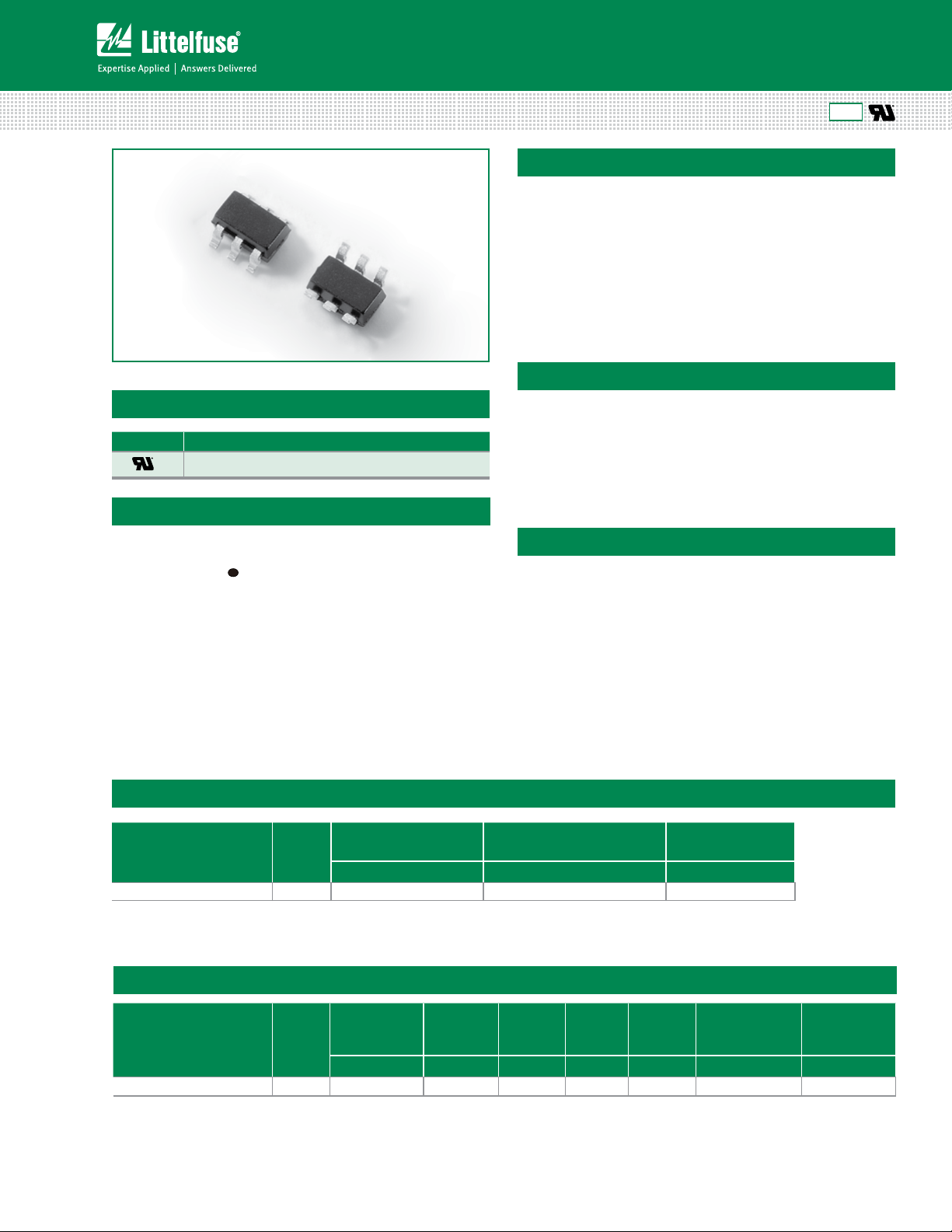
SIDACtor
Protection Thyristors
Broadband Optimized™ Protection
SDP Biased Series - SOT23-6
Agency Approvals
Agency Agency File Number
E133083
Pinout Designation & Schematic Symbol
RoHS
Description
This new SDP Biased series provides overvoltage
protection for applications such as VDSL2, ADSL2,
and ADSL2+ with minimal effect on data signals. This
silicon design innovation results in a capacitive loading
characteristic that is compatible with these high bandwidth
applications. This surface mount SOT23-6 package provides
a surge capability that exceeds most worldwide standards
and recommendations for lightning surge withstand
capability of tertiary protectors.
Features & Benefits
• Compatible with VDSL2
(30MHz)
• Balanced overvoltage
• Low prole
• Response time under
500ns
protection
• Low distortion
• Low insertion loss
Applicable Global Standards
1
6
• ANSI C62.41
• IEC 61000-4-12
• IEC 61000-4-5, 30A
2
3
5
4
(t
=8/20μs)
P
Absolute Maximum Ratings between pin1 and pin 3, Ta= 25ºC (Unless otherwise noted)
Part Number Marking
SDP0240T023G6RP
Notes:
1. The device must be in thermal equilibrium at 25ºC
P24 150 -65 to 150 30
Maximum Junction
Temperature
ºC ºC A Max
Storage Temperature Range
Electrical Characteristics between pin 1 and pin 3, Ta = 25°C
Part Number Marking
SDP0240T023G6RP
V
DRM
@I
=100nA
DRM
V min pA typ V max mA typ mA min pF max pF max
P24 19 300 29 40 10 3.0 0.5
@V
I
DRM
DRM
VS@1V/us I
=19V
H
I
S
• IEC 61000-4-2 level 4
-- 15kV (air discharge)
-- 8kV ( contact discharge)
I
pp
8/20µs
1
Delta Co@
Co@f=1MHz,2V
Line Bias
= 1 V to 19 V
© 2013 Littelfuse, Inc.
Specifications are subject to change without notice.
Revised: 11/04/13
1
SDP Biased Series SOT23-6
Page 2
®
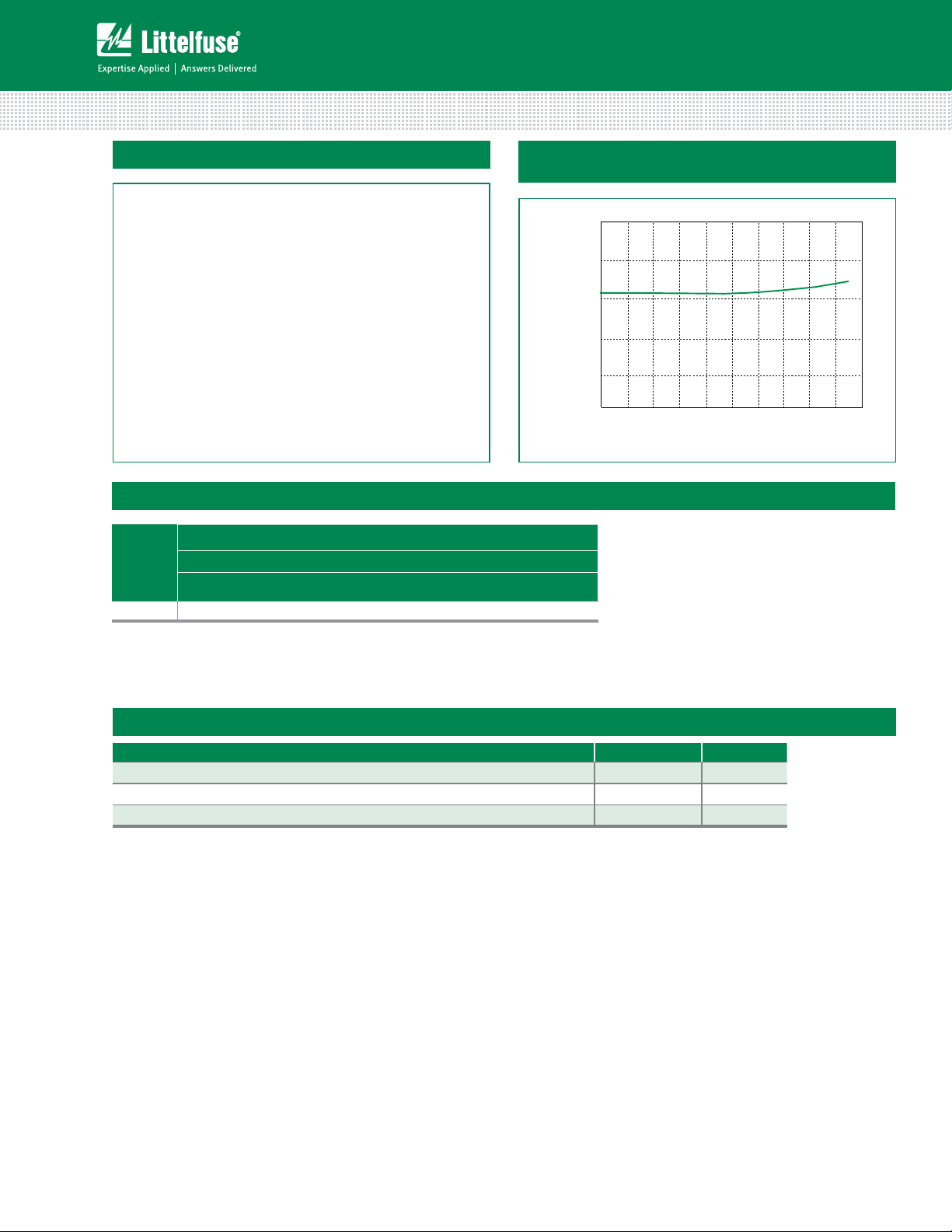
Voltage (Volt)
2.0
1.5
1.0
0.5
0.0
0
2
4
6
8101214
16
18 20
Capacitance (pF)
SIDACtor
Protection Thyristors
Broadband Optimized™ Protection
V-I: Characteristics
Surge Ratings
Series
G 30
Notes:
1 Volt age waveform in µs
2 Current waveform in µs
I
PP
1.2/50µs 1 / 8/20µs
A min
Typical capacitance against line voltage (without
external bias)
2
- Peak pulse current rating (I
- The device must be in thermal equilibrium at 25°C.
) is repetitive and guaranteed for the life of the product.
PP
Thermal Information
© 2013 Littelfuse, Inc.
Specifications are subject to change without notice.
Revised: 11/04/13
stinUgnitaRretemaraP
C˚051 ot 56-egnaR erutarepmeT egarotS
C˚051erutarepmeT noitcnuJ mumixaM
C˚062)s01 gniredloS( erutarepmeT daeL mumixaM
2
SDP Biased Series SOT23-6
Page 3

®
Junction Temperature (TJ) – °C
Percent of V
S
Change – %
1.08
1.06
1.04
1.02
1.00
0.98
0.96
-50 -25 0255075100 125150
Case Temperature ºC
1.2
1.1
1.0
0.9
0.8
0.7
0.6
-50 -25 0255075100 125150
Normalized I
H
SIDACtor
Protection Thyristors
Broadband Optimized™ Protection
Normalized VS Change vs. Junction Temperature
Soldering Parameters
Reflow Condition Pb-Free assembly
- Temperature Min (T
Pre Heat
Average ramp up rate (Liquidus Temp (T
to peak)
T
S(max)
Reflow
Peak Temp (TP) 250(+0/-5)°C
Time within 5°C of actual Peak Temp (t
Ramp-down Rate 6°C/sec. Max.
Time 25°C to Peak Temp (T
Do not exceed 260°C
- Temperature Max (T
- Time (Min to Max) (ts)
to TL - Ramp-up Rate
- Temperature (TL) (Liquidus)
- Temperature (tL)
)
s(min)
)
s(max)
)
P
)
L
)
p
150°C
200°C
60-180 secs.
3°C/sec. Max.
3°C/sec. Max.
+217°C
60-150 secs.
20-40 secs.
8 min. Max.
Normalized Holding Current vs. Case Temperature
© 2013 Littelfuse, Inc.
Specifications are subject to change without notice.
Revised: 11/04/13
3
SDP Biased Series SOT23-6
Page 4

®
O
P
R
M
Recommended Solder Pad Layout
SIDACtor
Protection Thyristors
Broadband Optimized™ Protection
Physical Specifications
Lead Plating SOT23: Matte Tin
Lead Material Copper Alloy
Lead Coplanarity 0.0004 inches (0.102mm)
Subsitute Material Silicon
Body Material Molded Epoxy
Flammability UL94-V-0
Notes:
1. All dimensions are in millimeters.
2. Dimensions include solder plating.
3. Dimensions are exclusive of mold ash & metal burr.
4. All specications comply to JEDEC MO-178
5. Blo is facing up for mold and facing down for trim/form, i.e. reverse trim/form.
6. Package surface matte tine
Dimensions - SOT23-6
Environmental Specifications
Mil-STD-883F, Method 1010.8 Condition
Temp Cycling
Bias Humidity
Pressure Cooker
High Temp Storage JESD 22-A103C Con B. 150°C, no bias 1000Hrs
HTRB
Thermal Shock
C-SAM
Wet Humidity
(Tin only)
C, -65°C to +150°C
168 Hrs, 85°C /60%RH+3IR-Reow,
260°C +5V, -0°C
JESD 22-A101-B 85°C , 85°CRH. 50V
168 Hrs, 85°C /60%RH+3IR-Reow,
260°C +5V, -0°C
JEDEC 22-A102C No Bias, 121°C,
100%RH 96Hrs/192Hrs.
168 Hrs, 85°C /60%RH+3IR-Reow,
260°C +5V, -0°C
JESD 22-108C
168 Hrs, 85°C /60%RH+3IR-Reow,
260°C +5V, -0°C
Mil-STD-883F, Method 1011.9 Condition
A, 0°C to 100°C
168 Hrs, 85°C /60%RH+3IR-Reow,
260°C +5V, -0°C
As per ow, JSTD-020C pre&post
preconditioning test.
JESD 201A standard: 55°C/85%RH
Dimensions
Inches Millimeters
Min Max Min Max
A - 0.057 - 1.450
A1 - 0.006 - 0.150
A2 - 0.051 - 1.300
b 0.014 0.020 0.350 0.508
C 0.004 0.008 0.090 0.200
D 0.110 0.118 2.800 3.000
E 0.102 0.118 2.600 3.000
E1 0.057 0.069 1.450 1.750
e - 0.037 - 0.950
e1 - 0.075 - 1.900
L (note 4.5) 0.004 0.023 0.100 0.600
N (note 6) 6 6
0°C 10°C 0°C 10°C
M - 0.102 - 2.590
O - 0.027 - 0.690
P - 0.039 - 0.990
R - 0.038 - 0.950
Notes:
1. Dimensioning and tolearances per ANSI 14.5M-1982.
2. Package conforms to EIAJ SC-74 (1992)
3. Dimensions D and E1 are exclusive of mold ash, protrusions, or gate burrs.
4. Foot lenth L measured at reference to seatng plane.
5. “L” is the length of at foot surface for soldering to substrate.
6. “N” is the number of terminal positions.
7. Controlling dimension: MILLIMETER. Converted inch dimensions are not necessarily
exact.
© 2013 Littelfuse, Inc.
Specifications are subject to change without notice.
Revised: 11/04/13
4
SDP Biased Series SOT23-6
Page 5

®
GENERAL INFORMATION
1. 3000 PIECES PER REEL.
2. ORDER IN MULTIPLES OF FULL REELS ONLY.
3. MEETS EIA-481 REVISION "A" SPECIFICATIONS.
2.0mm
4.0mm
C
L
1.75mm
1.5mm
DIA. HOLE
8mm
4.0mm
8.4mm
180mm
14.4mm
13mm
60mm
ACCESS HOLE
COVER TAPE
USER DIRECTION OF FEED
PIN 1
SOT-23 (8mm POCKET PITCH)
SIDACtor
Protection Thyristors
Broadband Optimized™ Protection
Part Numbering
Type
SIDACtor DSL Protector
Nominal Working voltage:
Construction variable:
0=single chip
SDP
024 0
T023 G
RP
6
Reel Pack
Number of pins
Surge Ipp rating
Package Type
Packing Options
Package Type Description Quantity
SOT23-6 Tape and Reel 3000
Embossed Carrier Tape & Reel Specification - SOT23-6
Part Marking
56
4
P24
123
Part Marking Code
© 2013 Littelfuse, Inc.
Specifications are subject to change without notice.
Revised: 11/04/13
5
SDP Biased Series SOT23-6
 Loading...