

Littelfuse SMA User Manual
SIDACtor
®
Baseband Protection (Voice-DS1)
SIDACtor® Series - SMA
Protection Thyristors
Description
SIDACtor® SMA Series are designed to protect
baseband equipment such as phones, faxes, modems,
line cards, CPE and DSL from damaging overvoltage
transients.
The series provides a surface mount solution that
enables equipment to comply with global regulatory
standards.
Features and Benefits
Agency Approvals
Agency Agency File Number
E133080
Schematic Symbol
• Low voltage overshoot
• Low on-state voltage
• Does not degrade
surge capability after
multiple surge events
within limit.
Applicable Global Standards
• TIA-968-A*
• TIA-968-B*
• ITU K.20/21 Enhanced
Level*
• ITU K.20/21 Basic Level
• Fails short circuit when
surged in excess of
ratings
• Low capacitance
• GR 1089 Intra-building
• IEC 61000-4-5*
• YD/T 1082
• YD/T 993
• YD/T 950
• GR 1089 Inter-building*
* Line impedance required to pass operationally
Electrical Characteristics
V
DRM
@l
Part Number Marking
P0080S1ALRP P-8A 6 25 50 800 2.2 4 25 35
P1800S1ALRP* P18A 170 220 15 0 800 2.2 4 15 50
P2300S1ALRP* P23A 190 260 150 800 2.2 4 15 50
P2600S1ALRP* P26A 220 300 150 800 2.2 4 15 50
P3100S1ALRP P31A 275 350 150 800 2.2 4 15 50
P3500S1ALRP* P35A 320 400 150 800 2.2 4 15 50
Notes:
- Absolute maximum ratings measured at TA= 25ºC (unless otherwise noted).
- Devices are bi-directional (unless otherwise noted).
- Parts with “*” are under development
=5µA
DRM
V min V max mA min mA max A max V max pF min pF max
V
S
@100V/µs
I
H
I
S
I
T
V
T
@IT=2.2 Amps
Capacitance
@1MHz, 2V bias
© 2012 Littelfuse, Inc.
Specifications are subject to change without notice.
Please refer to www.littelfuse.com for current information.
1
Revised: March 2, 2012
®
-I
50
100
0
t
r
t
d
0
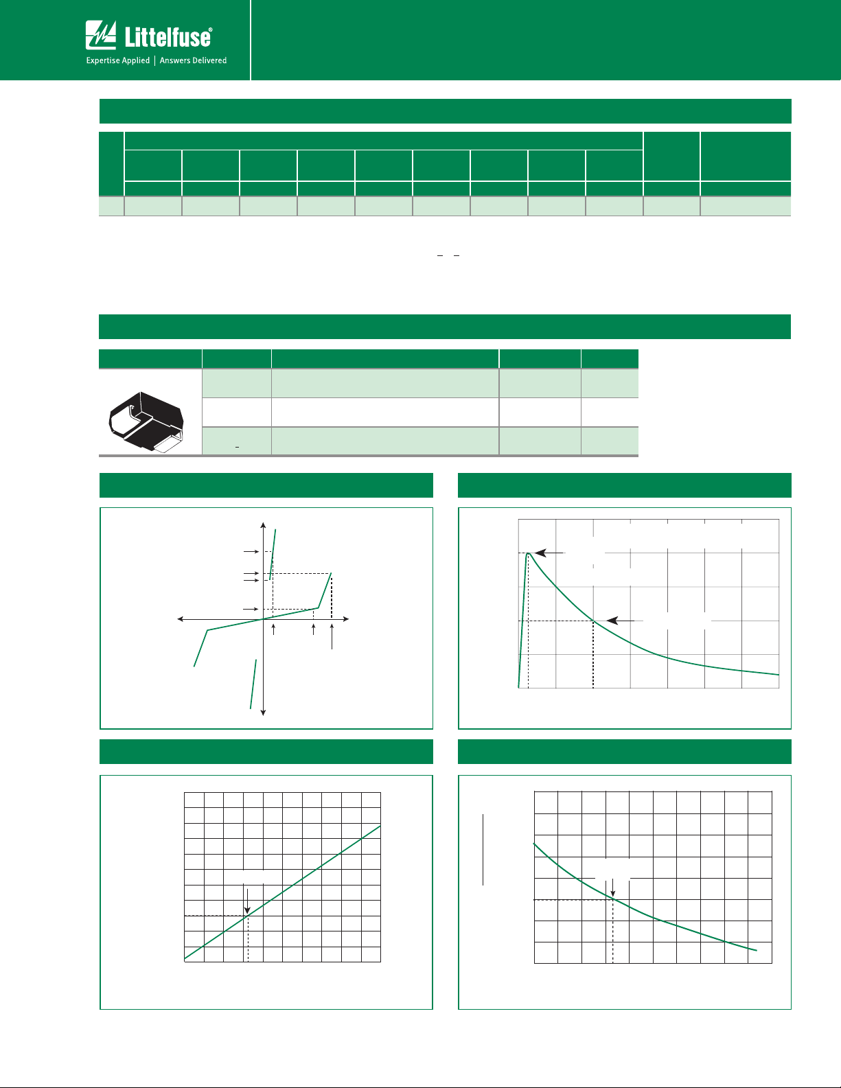
Peak
Value
Half Value
t – Time (µs)
I
PP
– Peak Pulse Current – %I
PP
tr = rise time to peak value
t
d
= decay time to half value
Waveform = t
r
x t
d
25°C
Case Temperature (TC) - ºC
2.0
1.8
1.6
1.4
1.2
1.0
0.8
0.6
0.4
-40 -20 020406080100 120140 160
Ratio of
I
H
I
H
(T
C
= 25ºC)
-8
-40 -20 020406080100 120140 160
-6
-4
0
2
4
6
8
10
12
14
Junction Temperature (TJ) – °C
Percent of V
S
Change – %
25 °C
SIDACtor
Protection Thyristors
Baseband Protection (Voice-DS1)
Surge Ratings
I
0.2x310
0.5x700
Series
1
2
2x10
2x10
1
2
8x20
1.2x50
1
2
10x160
10x160
1
2
PP
10x560
10x560
1
2
5x320
9x720
1
2
10x360
10x360
1
10x10 00
2
10x10 00
1
2
5x310
10x700
A min A min A min A min A min A min A min A min A min A min Amps/µs max
A 20 150 150 90 50 75 75 50 75 20 500
Notes:
1 Current waveform in µs
2 Volt age waveform in µs
- Peak pulse current rating (IPP) is repetitive and guaranteed for the life of the product.
- I
ratings applicable over temperature range of -40ºC to +85ºC
PP
- The device must initially be in thermal equilibrium with -40°C < T
< +150°C
J
Thermal Considerations
Package Symbol Parameter Value Unit
DO-214AC
T
J
Operating Junction Temperature Range -40 to +150 °C
1
2
I
TSM
50/60 Hz
di/dt
T
S
R
0JA
Storage Temperature Range -65 to +150 °C
Thermal Resistance: Junction to Ambient 90 °C/ W
V-I Characteristics tr x td Pulse Waveform
+I
I
T
I
S
I
H
I
-V
Normalized VS Change vs. Junction Temperature
DRM
+V
V
V
DRM
T
V
S
Normalized DC Holding Current vs. Case Temperature
© 2012 Littelfuse, Inc.
Specifications are subject to change without notice.
Please refer to www.littelfuse.com for current information.
2
Revised: March 2, 2012
 Loading...