

Page 1
Gas Discharge Tube (GDT) Products
SL1026 Series
SL1026 Series
Agency Approvals
AGENCY AGENCY FILE NUMBER
®
3 Electrode GDT Graphical Symbol
a
e
E128662
b
a = TIP
b = RING
e = GROUND
(centre electrode)
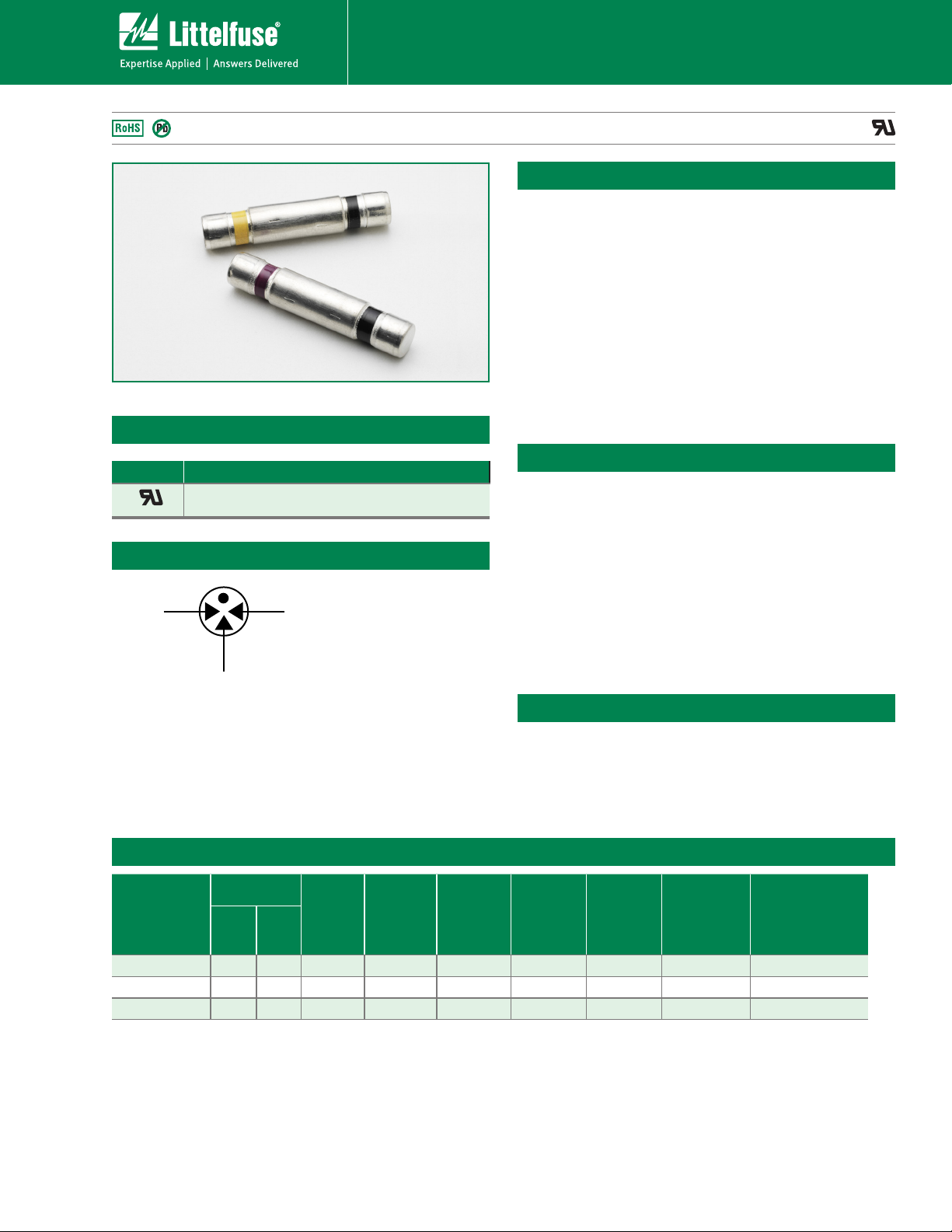
Description
The SL1026 Series is a heavy-duty transient
suppresser using Gas Plasma technology. In
response to transients that exceed the device's
breakover voltage, the device changes from a very
high impedance state to a low impedance state to
conduct harmful current away from the protected
system. The SL1026 is designed to protect electrical
and electronic equipment such as communications,
control and railway systems. Carefully designed
geometry ensures against short circuiting if a failure
occurs due to conditions and events beyond the
design criteria. Optional electrical mounting clip (part
SL1053 ) is available to aid mounting and connection.
Features
• RoHS compliant
• 55 kA surge capability
(single shot) tested with
8/20μS pulse as defined
by IEC 61000-4-5
• 40 kA surge capability
(repetitive)
• Will protect against
Trapezoidal waveforms
as specified in RIA 12.
• Will protect against
capacitor discharge
voltage transient
waveforms as specified
in RIA 12.
• Will protect against
double exponential
voltage transient
waveforms as specified
in IEC 571.
®
Applications
• Signaling equipment.
• Communication
equipment
• Trackside cabinets.
• Cell phone base
stations
• Control gear.
Electrical Characteristics
DC Voltage
100 V/sec
Part Number*
MIN MAX
SL1026-275 200 350 800 200 10 20 40 8 200
SL1026-400 300 500 900 200 10 20 40 8 200
SL1026-700 560 840 1300 200 10 20 40 8 200
NOTES:
End of life limits
-- DC: 50% of minimum initial DC breakdown voltage limit to 150% of maximum initial
DC breakdown voltage limit.
-- Impulse: less that 150% of initial impulse breakdown voltage limit.
1. Total current through center electrode, tested using SL1053B-NL holder
2. Exceeds capability of SL1053B-NL holder
DC
Voltage
1kV/µs
1
AC
Current
9 cycles
@50-60Hz
(Amps)
1
AC
Current
50Hz
1 sec x10
(Amps)
1
Surge
Current
8/20Sec
x 10
(kAmps)
1,2
Max
Single
Surge
8/20Sec
(kAmps)
1
Max Single
Surge
10/350Sec
(kAmps)
1
150(+) and 150(-)
10/1000Sec
(Amps)
©2009 Littelfuse, Inc.
Specifications are subject to change without notice.
Specifications are subject to change without notice.
Refer to www.littelfuse.com/series/SL1026.html for current information.
Please refer to www.littelfuse.com for current information.
Customer should verify actual device performance in their specific applications.
33
33
Revised: November 10, 2009
Revised: November 10, 2009
SL1026 Series
Page 2
Gas Discharge Tube (GDT) Products
SL1026 Series
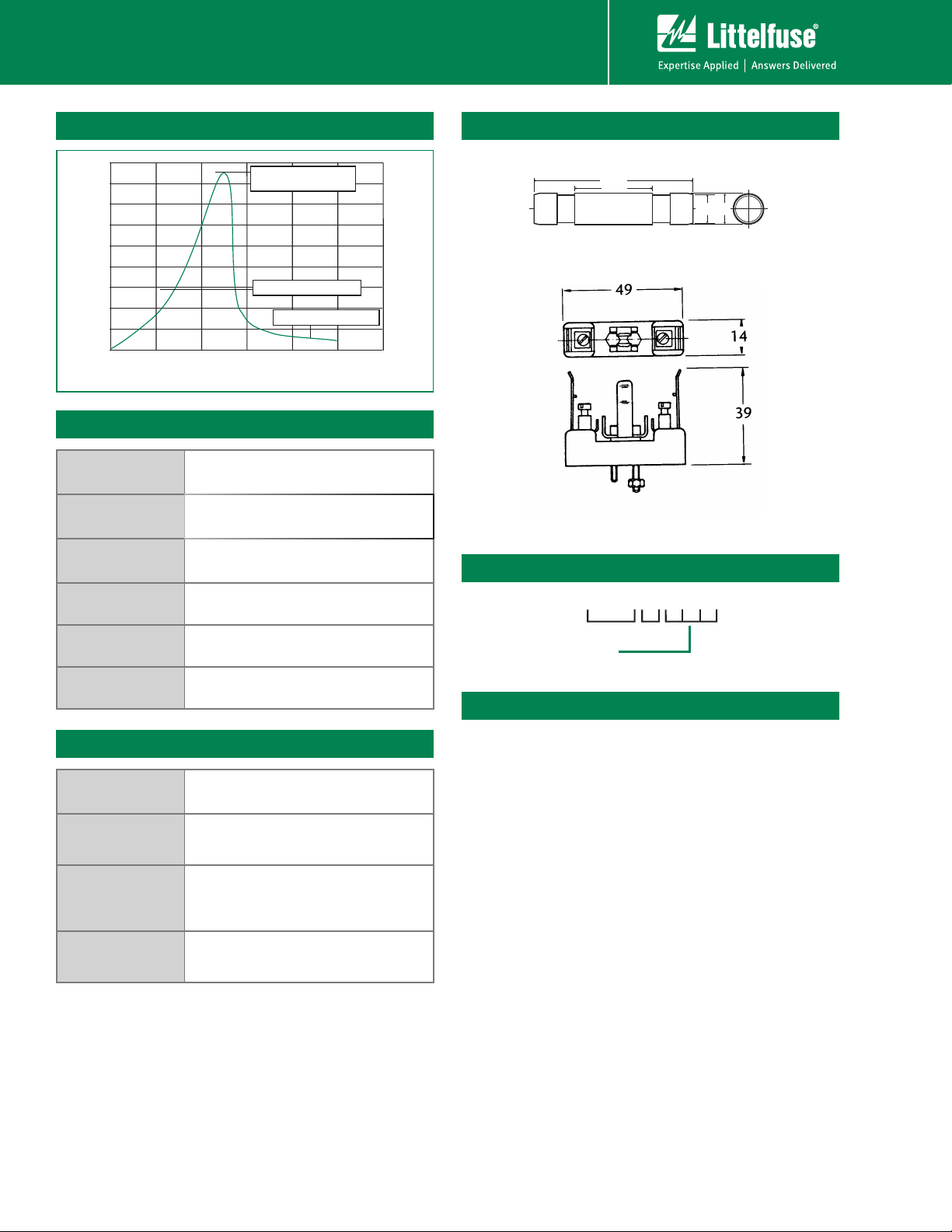
Voltage vs. Time Characteristic Product Dimensions
Max dynamic breakover
voltage
(V)
Voltage
Hold-over voltage
On-State voltage
0 200 400 600 800 1000 1200
Time (ns)
Electrical Specifications
Insulation
Resistance
Capacitance: <=2.5pf, 1MHz 0 Volts Bias
Holdover Voltage:
Arc Voltage:
Glow to Arc
Transition Current:
> 10GΩ at 100 Volts
<150mS, tested at 130 volts according to
ITU-T Rec. K.12 & REA PE 80
~35 Volts, On State Voltage at 1 Amp
(Depending on Voltage Type)
~1 Amp
SL1026 GDT Series Profile
45.0 Max
22.0 Ref
Type 1053 Holder Profile
All dimensions in mm
Part Numbering System
1026 –
SL
Voltage
Ø8.7
Max
Ø9.1
Max
Glow Voltage:
> 150 Volts, depending on Voltage
Type
Physical Specifications
Weight: 11g (0.388 oz.)
Materials:
Part Marking:
Storage and
Operating
Temperature:
Electrode Base: Nickel Iron Alloy
Electrode Plating: Nickel
Body: Ceramic
Color coded body
SL1026-275: Black/Black
SL1026-400: Black/Yellow
SL1026-700: Black/Red
-40°C to +90°C
Packaging
GDT devices are provided as bulk pack in poly bag --
20 pieces per bag and 5 bags per carton.
SL1026 Series
34
34
Revised: November 10, 2009
Revised: November 10, 2009
Specifications are subject to change without notice.
Specifications are subject to change without notice.
Please refer to www.littelfuse.com for current information.
Refer to www.littelfuse.com/series/SL1026.html for current information.
Customer should verify actual device performance in their specific applications.
©2009 Littelfuse, Inc.
 Loading...