

Page 1
Gas Discharge Tube (GDT) Products
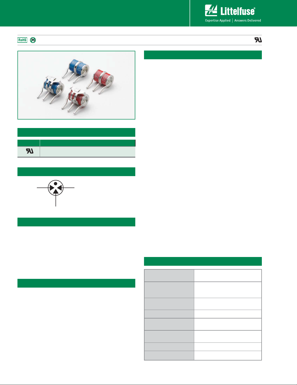
SL1021A/B, SL1024A/B and PMT8 Series
SL1021A/B, SL1024A/B and PMT8 Series
Agency Approvals
AGENCY AGENCY FILE NUMBER
®
3 Electrode GDT Graphical Symbol
a
e
Features
• RoHS compliant
• Low insertion loss
• Excellent response to
fast rising transients
• Ultra low capacitance
Applications
SL1021 / SL1024:
• Broadband equipment
• ADSL equipment
• XDSL equipment
• Satellite and CATV
equipment
• Splitters
• General telecom
equipment
E128662
b
a = TIP
b = RING
e = GROUND
(center electrode)
• 10KA (A suffix devices) /
20KA (B suffix devices)
surge capability tested
with 8/20s pulse as
defined by IEC 61000-4-5
• Available with thermal
failsafe option (add ‘F’
suffix to part number)
PMT8:
• Telecom network
interfaces
• Telephone line cards
• Repeaters
• Modems
• Line test equipment
®
Description
GDT circuit protection devices dissipate electrical
surge energy safely within a contained plasma gas.
Commonly used to help protect sensitive telecom and
networking equipment and lines, GDTs protect from
damage that may result from lightning strikes and
equipment switching operations.
The Littelfuse GDT series described in this document
are available in a variety of leaded and surface mount
forms and offered with and without optional failsafe clip. Please refer to the electrical specifications,
dimension and packaging options section of this
document for additional information.
SL1021A/B and SL1024A/B Series:
SL1021A/B and SL1024A/B series GDTs are designed
to offer high levels of performance on fast rising
transients in the range of 100V/S to 1KV/S, which
are those most likely created by induced lightning
disturbances.
These devices feature ultra low capacitance (typically
1.5pF or less) and are extremely robust with SL102xA
devices able to divert a 10,000 Amp pulse without
destruction, and SL102xB suffix devices able to divert
a 20,000 Amp pulse without destruction.
These series offer optimized internal geometry which
provide low insertion loss at high frequencies, ideal
for the protection of broadband and other high speed
transmission equipment.
PMT8 Series:
PMT8 GDT's are telecom grade devices designed to
meet the recommendations in CCITT-K12 and Bellcore
GR-1361-CORE. The three electrode configuration
is used in applications where simultaneous crowbar
action of two signal lines is required.
Product Characteristics
Materials
Product Marking
Glow to arc
transition current
Glow Voltage
Storage and Operation
Temperature
Transverse Voltage
(Delay Time)
Arc Voltage
Holdover Voltage
Dull Tin Plate 17.5 ± 12.5 Microns.
with ceramic insulator
‘LF’ mark, voltage& date code:
SL102xA - Red/White text
SL102xB & PMT8 - Blue/White text
~ 1Amp
~60-200 Volts
-40 to +90°C
< 0.2µSec (Tested to ITU-T Rec. K.12)
~10 to 35 Volts
<150mS (Tested to ITU-T Rec. K.12)
SL1021A/B, SL1024A/B and PMT8 Series
18
Revised: June 28, 2010
Specifications are subject to change without notice.
Customer should verify actual device performance in their specific applications.
Please refer to www.littelfuse.com for current information.
©2010 Littelfuse, Inc.
Page 2

Gas Discharge Tube (GDT) Products
SL1021A/B, SL1024A/B and PMT8 Series
Electrical Characteristics
Device Specifications (at 25°C) Life Ratings
Part
Number*
DC Voltage
100V/Sec.
MIN TYP MAX MIN
DC
Voltage
100 V/
Sec.
SL1021A090
SL1024A090
SL1021B090
SL1024B090
72 90 108
PMT 8 090
SL1021A145
SL1024A145
SL1021B145
116 145 174
500
SL1024B145
SL1021A150
SL1024A150
SL1021B150
120 150 180
SL1024B150
SL1021A200
150 200 250
SL1021A230
SL1024A230
SL1021B230
SL1024B230
184 230 276 450
PMT 8 230
SL1021A250
SL1024A250
SL1021B250
SL1024B250
200 250 300 500
PMT 8 250
SL1021A260
SL1024A260
SL1021B260
210 260 310 550 700
SL1024B260
SL1021A300
SL1024A300
SL1021B300
240 300 360 650 850
SL1024B300
SL1021A350
SL1024A350
SL1021B350
SL1024B350
280 350 420 700 900
PMT 8 350
SL1021A400
SL1024A400
SL1021B400
SL1024B400
PMT 8 400
320 400 480
850 950
SL1021A420
SL1024A420
SL1021B420
345 420 500
SL1024B420
SL1021A450
SL1024A450
SL1021B450
360 450 540 900 1000
SL1024B450
SL1021A500
SL1024A500
SL1021B500
400 500 600 950 1100
SL1024B500
SL1021A600
SL1024A600
NOTES:
*Max capacitance is 1.5 pF, measured at 1 MHz.
1. Total current through centre electrode, tested in accordance with ITU-T Rec K.12
2. SL A series
3. SL B series & PMT 8 series
480 600 720 1000 1200
DC
Voltage
1kV/
Sec.
650
600
650
Capaci-
tance
(@1Mhz)
<1.5pF
Insulation
Resistance
!
ȍ
DW9
!
ȍ
DW9
AC
Current
50Hz
1Sec.x10
10Amps
1
Surge
Current
8/20Sec
1
x10
10kA
20kA
2
3
Max
Single
Surge
8/20Sec
15kA
25kA
1
2
3
Max Single
Surge
10/350Sec
2
4kA
3
5kA
2
2.5kA
3
5kA
1
Surge Life
10/1000
Secx300
200Amps
1
©2010 Littelfuse, Inc.
Specifications are subject to change without notice.
Please refer to www.littelfuse.com for current information.
Customer should verify actual device performance in their specific applications.
19
Revised: June 28, 2010
SL1021A/B, SL1024A/B and PMT8 Series
Page 3

Gas Discharge Tube (GDT) Products
SL1021A/B, SL1024A/B and PMT8 Series
Time vs. Current for Failsafe
60
30
20
15
14
13
12
11
10
9
8
7
6
5
4
3
2
1
0.5
12 5 10 15 30
SL102xA with Failsafe
SL102xB or PMT8 500 Volt Higher Melting Point Solder
SL102xB or PMT8 350 Volt Higher Melting Point Solder
SL102xB or PMT8 90 Volt Higher Melting Point Solder
Voltage vs. Time Characteristic
Soldering Parameters - Reflow Soldering (Surface Mount Devices)
Reflow Condition Pb – Free assembly
- Temperature Min (T
Pre Heat
- Temperature Max (T
- Time (Min to Max) (ts) 60 – 180 secs
Average ramp up rate (Liquidus Temp
(T
) to peak
L
to TL - Ramp-up Rate 5°C/second max
T
S(max)
Reflow
- Temperature (TL) (Liquidus) 217°C
- Temperature (tL) 60 – 150 seconds
Peak Temperature (TP) 260
Time within 5°C of actual peak
Temperature (t
)
p
Ramp-down Rate 6°C/second max
Time 25°C to peak Temperature (T
Do not exceed 260°C
) 150°C
s(min)
) 200°C
s(max)
3°C/second max
+0/-5
°C
10 – 30 seconds
) 8 minutes Max.
P
T
Temperature
Soldering Parameters - Hand Soldering
Solder Iron Temperature: 350° C +/- 5°C
Heating Time: 5 seconds max.
Max dynamic breakover
voltage
(V)
Voltage
Hold-over voltage
On-State voltage
0 200 400 600 800 1000 1200
T
P
T
L
S(max)
T
S(min)
25
time to peak temperature
(t 25ºC to peak)
Preheat
t
S
Time (ns)
Ramp-up
t
P
t
L
Critical Zone
Ramp-down
Time
to T
T
L
P
Soldering Parameters - Wave Soldering (Thru-Hole Devices)
300
280
260
240
220
200
180
160
140
120
100
80
60
40
20
0
Temperature (°C) - Measured on bottom side of board
0
102030405060708090
Time (Seconds)
Preheat Time
SL1021A/B, SL1024A/B and PMT8 Series
100
110
120
130
140
150
160
170
180
190
200
210
220
230
Dwell Time
Cooling Time
Revised: June 28, 2010
Recommended Process Parameters:
Wave Parameter Lead-Free Recommendation
Preheat:
(Depends on Flux Activation Temperature)
Temperature Minimum:
Temperature Maximum:
Preheat Time: 60-180 seconds
Solder Pot Temperature:
Solder Dwell Time: 2-5 seconds
240
Note: Surge Arrestors with a Failsafe mechanism should be
individually examined after soldering
20
Customer should verify actual device performance in their specific applications.
(Typical Industry Recommendation)
100
° C
150
° C
280
° C Maximum
Specifications are subject to change without notice.
Please refer to www.littelfuse.com for current information.
©2010 Littelfuse, Inc.
Page 4

Gas Discharge Tube (GDT) Products
SL1021A/B, SL1024A/B and PMT8 Series
Device Dimensions
NOTE: Failsafe option dimensions shown in green.
Shaped Radial Leaded Devices:
12.4 ± 1
Type 04 / R
0.3mm
Minimum
Type 05 / P
0.3mm
Minimum
Gap
15
[0.590]
4.4
[0.173]
[0.173± 0.12]
Gap
15
[0.590]
4.4
[0.173]
[0.216± 0.12]
4.4± 0.3
5.5± 0.3
[0.488 ± 0.039]
11.8
[0.464]
10.10
[0.398]
12.4 ± 1
[0.488 ± 0.039]
11.8
[0.464]
10.10
[0.398]
16.8
[0.661]
4.4± 0.3
[0.173± 0.12]
16.8
[0.661]
5.5± 0.3
[0.216± 0.12]
9.9
[0.354]
9.9
[0.354]
1.0 DIA.
[0.039]
1.0 DIA.
[0.039]
Mounting Area
Mounting Area
9.0
[0.354]
8.1.
[0.319]
9.0
[0.354]
8.1.
[0.319]
Surface Mount Devices:
Type 01 / C
0.3mm
Minimum
Gap
Type 60
8.3 +0.3/-0.0
[0.327
+0.019/-0.00]
7.7 ± 0.3
[0.303 ± 0.019]
PROFILE VIEW
1.2 ± 0.0
[0.047 ± 0.000]
6.0 ± 0.0
[0.236 ± 0.000]
11.8
[0.464]
10.10
[0.398]
10.0 ± 0.3
[0.394 ± 0.019]
Ø7.0 ± 0.1
[0.275 ± 0.004]
SIDE VIEW
10.75 ± 0.0
[0.423 ± 0.000]
SOLDERING PAD LAYOUT
9.9
[0.354]
2.2 ± 0.0
[0.087 ± 0.000]
Mounting Area
TOP VIEW
1.2 ± 0.0
[0.047 ± 0.000]
8.5 ± 0.0
[0.335 ± 0.000]
Overall Product Space
DO NOT ENCROACH
9.0
[0.354]
8.1
[0.319]
8.0 +0.3/-0.1
[0.315
+0.019/-0.004]
Straight "T" Leaded Devices:
Type 14 / X
0.3mm
Minimum
Gap
[0.866]
22
50 ± 3
[1.968 ± 0.118 ]
11.8
[0.464]
10.10
[0.398]
23.8
[0.937]
1.0 DIA..
[0.039]
Mounting Area
9.0
[0.354]
8.1 DIA. MAX.
[0.319]
Straight Radial Leaded Devices:
14.7
Type 06 / Y
0.3mm
Minimum
Gap
[0.25 ± 0.25]
15
[0.590]
6.35 ± 0.5
[0.579]
11.8
[0.464]
10.10
[0.398]
9.9
[0.354]
16.8
[0.661]
6.35 ± 0.5
[0.25 ± 0.25]
1.0 DIA.
[0.039]
Mounting Area
9.0
[0.354]
8.1 DIA. MAX.
[0.319]
©2010 Littelfuse, Inc.
Specifications are subject to change without notice.
Please refer to www.littelfuse.com for current information.
Customer should verify actual device performance in their specific applications.
21
Revised: June 28, 2010
SL1021A/B, SL1024A/B and PMT8 Series
Page 5

Gas Discharge Tube (GDT) Products
SL1021A/B, SL1024A/B and PMT8 Series
Part Numbering System and Ordering Information
SL102x x xxx x x
Series
SL1021
SL1024
Surge Capability
A = 10kA
B = 20kA
Breakdown Voltage
090 = 90V
145 = 145V
150 = 150V
200 = 200V
230 = 230V
250 = 250V
260 = 260V
Configuration Code
(See Device Dimensions section)
C
R
P
Option Code
Blank = No failsafe
F or G = With Failsafe
300 = 300V
350 = 350V
400 = 400V
420 = 420V
450 = 450V
500 = 500V
600 = 600V
Y
X
Series
PMT8
Breakdown Voltage
090 = 90V
230 = 230V
250 = 250V
350 = 350V
400 = 400V
Configuration Code
(See Device Dimensions section)
01
04
05
06
Option Code
Blank = No Failsafe
F = With Failsafe
PMT8 xxx x x
10
14
60
Packaging
Device Type Description Quantity
Type 01 / C 100pcs/tray x 5 trays per carton 500
Type 04 / R 100pcs/tray x 5 trays per carton 500
Type 05 / P 100pcs/tray x 5 trays per carton 500
Type 06 / Y 100pcs/tray x 5 trays per carton 500
Type 14 / X 50pcs/tray x 5 trays per carton 250
Type 60 500pcs/reel* x 10 reels per carton 5000
* For tape and reel specifications, please contact factory.
SL1021A/B, SL1024A/B and PMT8 Series
22
Revised: June 28, 2010
Specifications are subject to change without notice.
Customer should verify actual device performance in their specific applications.
Please refer to www.littelfuse.com for current information.
©2010 Littelfuse, Inc.
 Loading...