

Page 1
335
www.littelfuse.com
8
GAS DISCHARGE
TUBES
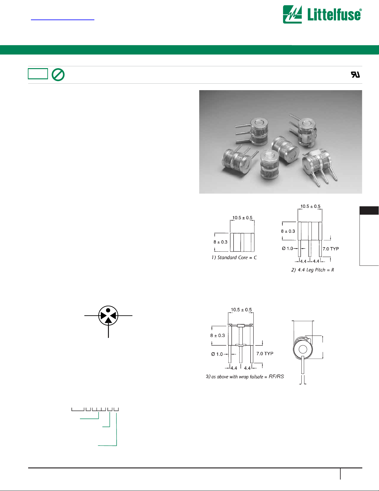
Gas Discharge Tubes
High Performance Beta Range
3 ELECTRODE GDT
a=TIP
b=RING
e=GROUND
(centre electrode)
GRAPHICAL SYMBOL
a
b
e
All dimensions in mm
ORDERING INFORMATION
Greentube™ SL1021A Series Gas Plasma Arresters
ø8.0+_0.2
9.5 MAX
ø1.0+_0.2
The SL1021A series offers high levels of performance on fast rising transients in the domain of 100V/µS to 1KV/µS, which are
those most likely from induced Lightning disturbances. The
SL1021A series also features ultra low capacitance (typically 1pF
or less) and optimised internal geometry which provides low
insertion loss at high frequencies, so are ideal for the protection
of broadband equipment. These devices are extremely robust
and are able to divert a 10,000Amp pulse without destruction.
FEATURES
• RoHS compliant except ‘RS’ suffix
• Low insertion loss
•
Excellent response to fast rising transients.
• Ultra low capacitance.
• 10KA surge capability tested with 8/20µs pulse as defined by
IEC 61000-4-5
• 20,000 A single shot surge capability tested with 8/20µs
pulse as defined by IEC 61000-4-5
• Available with thermal failsafe option
(add ‘F’ or ‘S’ suffix to part number)
• ROHS Compliant
Applications:
• Broadband equipment.
• ADSL equipment.
• XDSL equipment.
• Satellite and CATV equipment.
• General telecom equipment.
Mechanical Specifications:
Weight: 2.7g (0.095 oz.)
Materials: Electrode Base: Nickel Iron Alloy
Electrode Plating: Bright Sn
Body: Ceramic
Device Marking: Littelfuse ‘LF’ marking, Voltage and
date code.
®
SL1021A xxxC
SL1021A xxxR
SL1021A xxxRF
SL1021A xxxRS
查询SL1021A供应商
RoHS
Pb
1021 A
SL
Voltage
Pin Configuration
C=Core
R=Leaded
Failsafe Optio
F=Plastic
S=Solder
n
Page 2
336
www.littelfuse.com
Gas Discharge Tubes
Part Number
SL1021A145
SL1021A150
SL1021A200
6
SL1021A230
SL1021A250
SL1021A260
7
SL1021A300
SL1021A350
SL1021A400
SL1021A420
SL1021A450
SL1021A500
SL1021A600
DC Voltage
@ 100V/sec
(V)
145
150
200
230
250
260
300
350
400
420
450
500
600
DC
Breakover
Voltage
Min-Max
(V)
116-174
120-180
150-250
184-276
200-300
210-310
240-360
280-420
320-480
345-500
360-540
400-500
480-720
DC
Dynamic
Breakover
Voltage @
100/µs (V)
500
500
350
350
400
420
450
500
550
600
650
700
850
Max
Alternating
Discharge
Current
1,3
(A)
10
10
10
10
10
10
10
10
10
10
10
10
10
Max Single
Impulse
Discharge
Current
10/350µs
5
(kA)
2.5
2.5
2.5
2.5
2.5
2.5
2.5
2.5
2.5
2.5
2.5
2.5
2.5
Max Single
Impulse
Discharge
Current
8/20µs
5
(kA)
20
20
20
20
20
20
20
20
20
20
20
20
20
Max
Repetitive
Impulse
Discharge
Current
8/20µs
1,4
(kA)
10
10
10
10
10
10
10
10
10
10
10
10
10
Life Test
Rating
2
100 shots
100 shots
100 shots
100 shots
100 shots
100 shots
100 shots
100 shots
100 shots
100 shots
100 shots
100 shots
100 shots
(1) Total current through center (ground) electrode, both line electrodes pulsed simultaneously; half value through
each respective line terminal.
(2) 100 amps, 10/1000
µS pulse (does not apply to SL1021A200)
(3) 10 shots, A.C. 60Hz, 1 sec duration.
(4) 10 shots, 8/20
µS waveform
(5) either end (line) electrode to centre (ground) electrode
(6) Meets the requirements of BT Type 21A.
(7) Meets the requirements of BT Type 14A. Addition of ‘F’ (failsafe) option meets the requirements of BT type
number 14A/1.
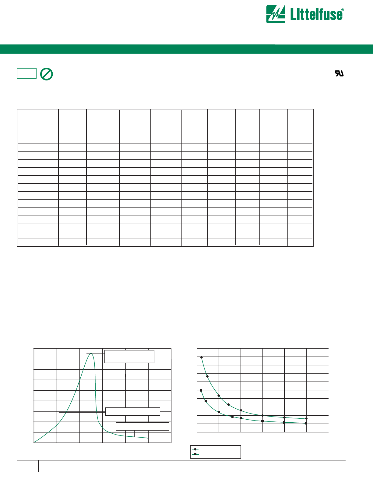
LITTELFUSE 3 TERMINAL ARRESTER SERIES
TOTALLY NON-RADIOACTIVE, UL RECOGNIZED
Greentube™ SL1021A Series Gas Plasma Arresters
High Performance Beta Range
Single
Impulse
Discharge
Current
8
(kA)
40
40
40
40
40
40
40
40
40
40
40
40
40
50
45
40
35
30
25
20
15
10
5
0
0 1 2 3 4 5 6
Current
(A)
(s)
1 line to ground
both lines to ground
Time vs. Current for Failsafe
®
RoHS
Pb
Voltage vs Time Characteristic
Max dynamic breakover
voltage
(V)
Voltage
Hold-over voltage
On-State voltage
0 200 400 600 800 1000 1200
Time (ns)
Page 3

337
www.littelfuse.com
8
GAS DISCHARGE
TUBES
Gas Discharge Tubes
Greentube™ SL1021A Series Gas Plasma Arresters
High Performance Beta Range
®
Solder T1 max = 266oC
Flow Area
T
1
= 239oC
200
300
Tm = 179oC
Forced Cooling
Preheating
Area
100
10 20 30 40
Time (seconds)
Temperature (˚C)
Profile for wave soldering
Notes:
T1 max
= Maximum Tab Temperature = 266oC
T
1
= Flow Tempearture of Solder = 239oC
Tm
= Melting Point of Solder = 179oC
Tamb
= 25
o
C
Maximum
p
ermissible rate of temperature change =
7
o
C / sec
RoHS
250
225
200
175
150
125
100
Temperature ˚C
75
50
25
0
0
Pb
Profile for reflowsoldering
50 100 150 200 250 300 350 400 450 500
Time in seconds
Page 4

338
www.littelfuse.com
Gas Discharge Tubes
ORDERING INFORMATION
Greentube™ SL1021B Series Gas Plasma Arresters
3 ELECTRODE GDT
a=TIP
b=RING
e=GROUND
(centre electrode)
GRAPHICAL SYMBOL
a
b
e
High Performance Beta Range
All dimensions in mm
The SL1021B series offers high levels of performance on fast rising transients in the domain of 100V/µS to 1KV/µS, which are
those most likely from induced Lightning disturbances. The
SL1021B series also features ultra low capacitance (typically 1pF
or less) and optimised internal geometry which provides low
insertion loss at high frequencies, so are ideal for the protection
of broadband equipment. These devices are extremely robust
and are able to divert a 20,000Amp pulse without destruction.
FEATURES
• RoHS compliant except ‘RS’ suffix
• Low insertion loss
• Excellent response to fast rising transients.
• Ultra low capacitance.
• 10KA surge capability tested with 8/20µS pulse as defined by
IEC 6100-4-5
• 20,000 A single shot surge capability tested with 8/20µs
pulse as defined by IEC 6100-4-5
• Available with thermal failsafe option (add ‘F’ or ‘S’ suffix to
part number)
Applications:
• Broadband equipment.
• ADSL equipment.
• XDSL equipment.
• Satellite and CATV equipment.
• General telecom equipment.
Mechanical Specifications:
Weight: 0.63g (0.022 oz.)
Materials: Electrode Base: Nickel Iron Alloy
Electrode Plating: Bright Sn
Body: Ceramic
Device Marking: Littelfuse ‘LF’ marking, Voltage and date
code. Blue.
®
SL1021A xxxC
SL1021B xxxR
SL1021B xxxRF
SL1021B xxxRS
RoHS
Pb
ø8.0+_0.2
9.5 MAX
ø1.0+_0.2
SL
1021 B
Voltage
Pin Configuration
C=Core
R=Leaded
Failsafe Optio
F=Plastic
S=Solder
n
 Loading...