

Page 1
Generator Control
Advanced
SIGMA SERIES
Generator Control and Protection System
1
2
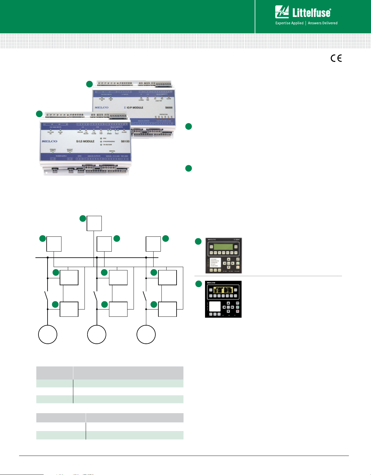
Simplified Circuit Diagram
A
S6610
(Power
Manager
Module)
B B B
S6500
(User-Interface
Module)
2 2 2
S6100
(Synchronizing &
Load-Sharing
Module)
1 1 1
S6000
(Input/Output &
Protection
Module)
S6500
(User-Interface
Module)
S6100
(Synchronizing &
Load-Sharing
Module)
S6000
(Input/Output &
Protection
Module)
S6500
(User-Interface
Module)
S6100
(Synchronizing &
Load-Sharing
Module)
S6000
(Input/Output &
Protection
Module)
Description
The SIGMA Generator Control and Protection System is a range of
integrated modules for protection and control of marine and land
based generators. The modules are marine approved and include all
relevant functions, such as protection of generators, synchronizing
and active/ reactive load sharing and Power Management.
IO/P Module S6000
1
Input/ Output and Protection Module
The SIGMA S6000 performs all measurements on the
generator side (voltages, currents, frequency), does the
generator protection, includes a non-essential load trip in
two steps and includes three measurement transducers.
S/LS Module S6100
2
Synchronizing and Load-Sharing Module
This module performs the control functions like synchronizing
and active and reactive load sharing. It performs the
measurements on the busbar side.
Accessories
A
B
Gen.
Amp.
Misc.
Volt.
kW kVAr Prot.
C/B CLOSED
PROTECTION TRIP
IN OPERATION
Mode
OFF DUTY
ENGINE ERROR
Duty
Reset Test
S6610 Power Manager Module
Controls the number of generators that are
supplying to the bus. It will issue start and
stop signals to the generators depending
on power requirement. There are 10 inputs
for large consumer requests.
SIGMA
Σ
S6500 User Interface Module
Page
This unit is optional, as the S6000/S6100
PAGE
PM
DOWN
also can be programmed from a PC.
Enter
Enter
It is possible to use one or more units
Yes
per installation.
No
ALARMPWR1 PWR2
GEN
A
GEN
B
Ordering Information
ORDERING
NUMBER
S6000.0010 Input/ Output and Protection Module– 5 A C/T
S6000.0020 Input/ Output and Protection Module–1 A C/T
S6100.0010 Synchronization and Load Sharing Module
ACCESSORIES REQUIREMENT
S6500.0010 Optional
S6610.0010 Optional
© 2013 Littelfuse Protection Relays & Controls
www.littelfuse.com/s6000
DESCRIPTION
GEN
C
Rev: 4-A-050313
Page 2
Generator Control
Sync On
Frequency Control
SHAFT GENERATOR
(GRID)
Next S6000 / S6100
Next S6100
Advanced
SIGMA Technical Data
FEATURES
Reverse power protection
Overcurrent trip
Short-circuit trip
Power trip
Excitation loss relay trip
Over/ Undervoltage trip
Nonessential load trip in 2 steps
RS485/ Modbus RTU (RS485)
Synchronizer
Load sharer
VAR load sharer
Indication of measurements
Programming of the
S6000 and S6100 modules
Load depending start and
stop of generators
Large consumer request
Large consumer inhibit
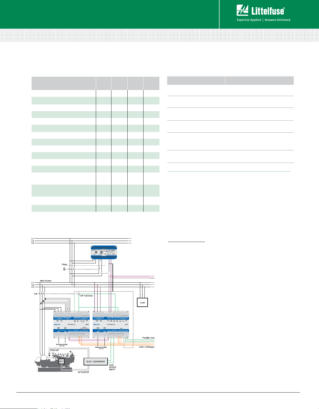
Wiring Diagram
SIGMA
S6000
•
•
•
•
•
•
•
•
S/LS
MODULE
S6100
•
•
•
PM
MODULE
S6610
• •
• •
•
•
•
UI
MODULE
S6500
Features & Benefits
FEATURES BENEFITS
3-phase true RMS
measurement
Analog outputs for speed
and voltage control
PWM outputs for speed
and voltage control
Pulse outputs for speed
and voltage control
Large consumer request
inputs with load feed back
Type-approved by marine
classification societies
Reliable measurement, high noise immunity
Fits most elec tronic governors and ECUs
Compatible with e.g. CAT and Woodward
Compatible with conventional governors,
motorized potentiometers and some ECUs
Optimizes quantity of running generators
and saves fuel
Pre-configured Marine Power
Management System
Specifications (S6000)
Primary Supply +24 Vdc (-30%/+30 %) Isolated, 500 mA
Backup Supply +24 Vdc (-30%/+30 %) Isolated, 500 mA
Environmental Temp Range –15°C to +70°C
Gen. Phase-Phase Voltage (GPPV) 63.0-690.0 Vac (-2 % /+2 %) 3-phased
Gen. Indicated Voltage (GIV) 63-32 kV AC
CT Secondary Current (CTSC) 1 A or 5 A (consumption 25 mW or
125 mW) 3-phased
Gen. Rated Frequency (GRF) 40.0 -500.0 Hz
Gen. Maximum Current (GMC) 0.5-3,000.0 A / 500-30,000 A
Protection Functions
C/B Trip Relay Contact rating: AC: 8 A, 250 Vac; DC: 8 A, 35 Vdc
NE1 Trip Relay Contact rating: AC: 8 A, 250 Vac; DC: 8 A, 35 Vdc
NE2 Trip Relay Contact rating: AC: 8 A, 250 Vac; DC: 8 A, 35 Vdc
Alarm Relay Contact rating: AC: 8 A, 250 Vac; DC: 8 A, 35 Vdc
CAN Bus Connection: Screw terminals,2-wire with COM
Protocol: CANopen derivative
RS232 Connection: Customized plug, 4-wire (non-isolated)
Function: Configuration, Debugging or
firmware update
Protocol: ANSI terminal
RS485 Connection: Screw terminals, 2-wire (isolated)
Protocol: MODBUS-RTU
EMC EN 50081-2:1993, EN 50263: 1999
Marine Tests EN 60945:1997, IACS E10:1997
Connections Plug-in screw terminals
(spring terminals available as option)
Mounting Screw mounting (4 pcs. 4.2 x 12 mm)
Weight 1,150 g
Dimensions H 145 mm (5.7”)
W 190 mm (7.5”)
D 64.5 mm (2.5”)
(limp back function)
© 2013 Littelfuse Protection Relays & Controls
www.littelfuse.com/s6100
Rev: 4-A-050313
 Loading...