

Littelfuse SE-330 User Manual
3714 Kinnear Place Saskatoon, SK Canada S7P 0A6 Ph: (306) 373-5505 Fx: (306) 374-2245 www.littelfuse.com/relayscontrols
SE-330 MANUAL
NEUTRAL-GROUNDING-RESISTOR MONITOR
REVISION 10-D-112913
LITTELFUSE STARTCO
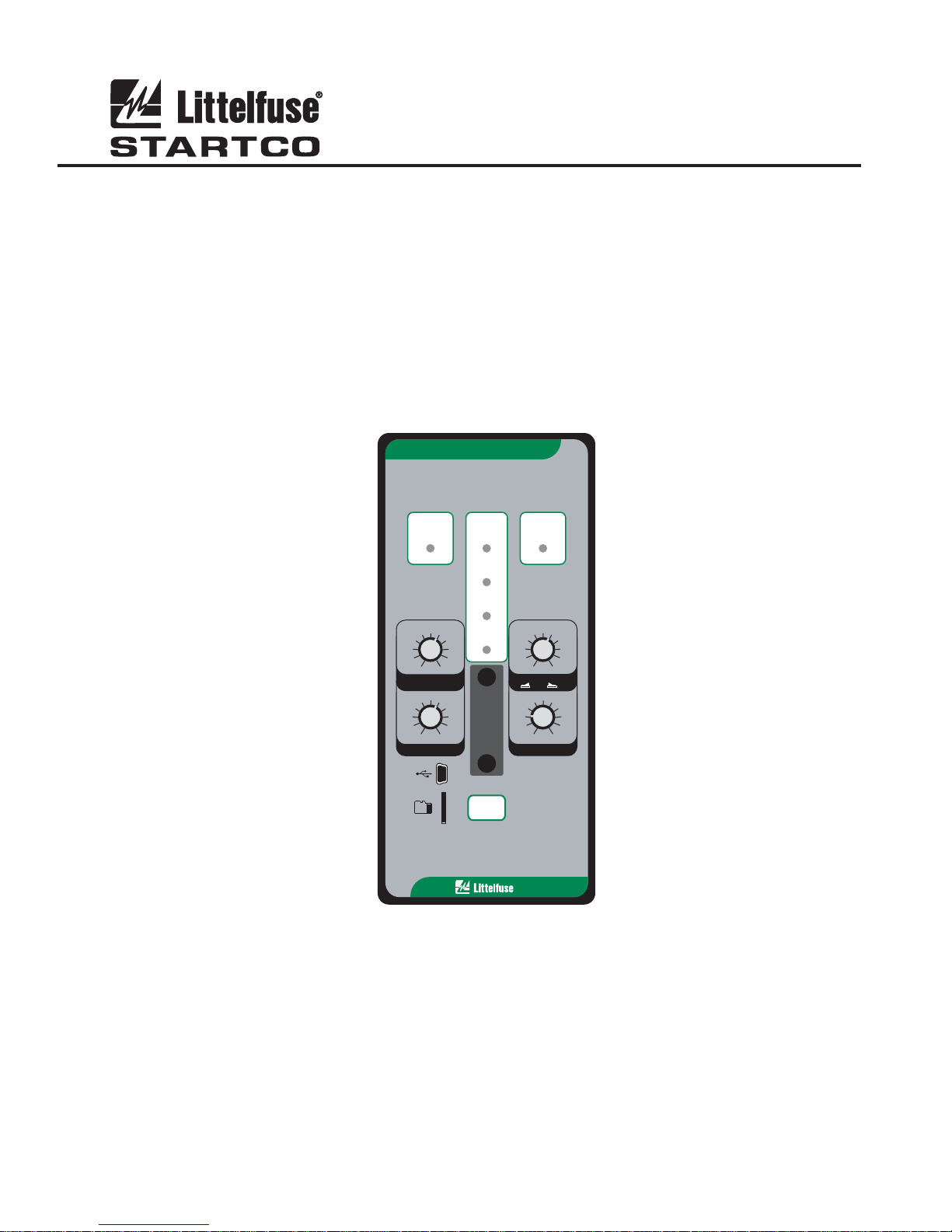
MONITOR
SE-330NEUTRAL-GROUNDING-RESISTOR
Document Number: PM-1200-EN
Printed in Canada.
GROUND
FAULT
10
8
680
4
GF TRIP LEVEL
(% CT RATING)
0.5
0.4
0.3
0.2
0.1
GF TRIP TIME (s)
TRIP
DIAGNOSTIC
CALIBRATED
RELAY K1
20
40
60
POWER
100
MEM2
0.7
1.0
2.0
3.0
5.0
10.0
RESET
RESISTOR
FAULT
TRIP
200
170
340
130
100 1200
60
200020
V TRIP LEVEL
N
20 K
Ω
100 K
S5
()
N
Vx 1
Vx 5
2.0
1.8
CAL
2.2
1.6
1.4
1.2
1.0
3.0
PULSE PERIOD (s)
800
1700
N
2.4
2.6
2.8
Ω
Copyright 2013 Littelfuse Startco
All rights reserved.

Page i
SE-330 Neutral-Grounding-Resistor Monitor Rev. 10-D-112913
This page intentionally left blank.

Page ii
TABLE OF CONTENTS
SECTION PAGE
1. General ................................................................. 1
1.1 Modern Resistance-Grounded Systems ................ 1
1.2 SE-330 NGR Monitoring ...................................... 1
2. Operation ............................................................. 2
2.1 Settings .................................................................. 2
2.1.1 GF Trip Time ............................................. 2
2.1.2 GF Trip Level ............................................ 2
2.1.3 V
2.1.4 Pulse-Period Adjustment ........................... 3
2.1.5 Configuration Settings ............................... 3
2.1.5.1 Relay K1 Function (S1) ................ 4
2.1.5.2 Trip-Relay Mode and
Trip-Memory Mode (S2) ........................... 4
2.1.5.3 Ground-Fault-Trip Latch (S3) ....... 4
2.1.5.4 Resistor-Fault-Trip Latch (S4) ...... 4
2.1.5.5 Sensing-Resistor Selection (S5) .... 4
2.1.5.6 Frequency (S6) .............................. 4
2.1.5.7 Upgrade Mode (S8) ....................... 4
2.2 Calibration ............................................................. 4
2.3 Pulsing Operation .................................................. 5
2.4 Trip Indication and Reset ...................................... 5
2.5 Remote Operation ................................................. 5
2.6 Relay K1 LED ....................................................... 5
2.7 Unit Healthy Output .............................................. 5
2.8 Diagnostic LED..................................................... 5
2.9 Analog Output ....................................................... 6
3. Installation ........................................................... 6
3.1 SE-330 .................................................................. 6
3.2 Sensing Resistor .................................................. 12
3.3 Ground-Fault CT ................................................. 20
3.4 Isolated Ground Connection ............................... 25
3.5 Pulsing Connection ............................................. 25
4. Data Interfaces .................................................. 26
4.1 SD Card ............................................................... 26
4.1.1 Datalogging .............................................. 26
4.1.2 Firmware Upgrade ................................... 26
4.2 USB Interface ...................................................... 26
4.3 Network Communications .................................. 26
5. Troubleshooting ................................................ 27
6. Technical Specifications.................................... 28
6.1 SE-330 ................................................................ 28
6.2 Sensing Resistors ................................................ 29
6.3 Current Sensors ................................................... 30
7. Ordering Information ....................................... 31
8. Warranty ........................................................... 32
9. Test Procedures ................................................. 33
9.1 Resistor-Fault Tests ............................................. 33
9.1.1 Calibration and Open Test ....................... 33
9.1.2 Voltage Test ............................................. 33
9.2 Sensing-Resistor Test .......................................... 33
9.3 Analog-Output Test ............................................. 33
9.4 Ground-Fault Performance Test .......................... 34
Appendix A SE-330 Revision History ............................. 35
SE-330 Neutral-Grounding-Resistor Monitor Rev. 10-D-112913
LIST OF FIGURES
FIGURE PAGE
1 Configuration Switches ............................................ 3
2 Analog-Output Connections ..................................... 6
3 SE-330 Connection Diagram .................................... 7
4 SE-330 Outline and Panel-Mounting Details ........... 8
5 SE-330 Outline and Surface-Mounting Details ........ 9
6 SE-IP65CVR-G Weatherproof Cover Outline ....... 10
7 SE-IP65CVR-G Weatherproof Cover Installation . 11
Trip Level ............................................. 2
N
8 ER-600VC Sensing Resistor .................................. 12
9 SE-MRE-600 Moisture-Resistant Enclosure Outline 13
10 ER-600VC Installed in SE-MRE-600 ...................... 14
11 ER-5KV Sensing Resistor ...................................... 15
12 ER-5WP Sensing Resistor ...................................... 16
13 ER-15KV Sensing Resistor .................................... 17
14 ER-25KV Sensing Resistor .................................... 18
15 ER-35KV Sensing Resistor .................................... 19
16 EFCT-1 Sensitive Ground-Fault Current
Sensor ..................................................................... 21
17 SE-CS30-70 Sensitive Ground-Fault
Current Sensor ........................................................ 22
18 EFCT-26 and SE-CS30-26 Sensitive Ground-
Fault Current Sensors ............................................. 23
19 RK-332 Remote Indication and Reset .................... 24
20 PGA-0520 Analog Percent Current Meter ............. 24
21 Simplified Isolated-Ground Connection ................. 25
22 Simplified Pulsing Connection ............................... 25
23 Ground-Fault-Test Circuits .................................... 34
LIST OF TABLES
TABLE PAGE
1 Typical Values for Tripping Systems ....................... 3
2 Ground-Fault Trip Levels for Selected CT’s ............ 3
3 Ground-Fault-Test Record ...................................... 34
DISCLAIMER
Specifications are subject to change without notice.
Littelfuse Startco is not liable for contingent or
consequential damages, or for expenses sustained as a result
of incorrect application, incorrect adjustment, or a
malfunction.

Page iii
SE-330 Neutral-Grounding-Resistor Monitor Rev. 10-D-112913
This page intentionally left blank.

Page 1
SE-330 Neutral-Grounding-Resistor Monitor Rev. 10-D-112913
1. GENERAL
1.1 MODERN RESISTANCE-GROUNDED SYSTEMS
A high-resistance-grounded system uses a neutralgrounding resistor (NGR) with a low let-through current
to limit ground-fault current. This is an improvement
over low-resistance or solidly-grounded systems because,
in those systems, a ground-fault flash hazard exists and a
ground fault can result in substantial point-of-fault
damage. High-resistance grounding eliminates these
problems and modern ground-fault protection operates
reliably at low current levels. Furthermore, the
probability of an arc-flash incident is significantly
reduced in a high-resistance-grounded system.
NGR selection depends on system charging current and
whether the system is an alarm-only or a tripping system.
Alarm-only systems are usually restricted to system
voltages up to 5 kV with NGR let-through currents of 5 A
or less. Occasionally, alarm-only systems up to 15 kV
and up to 10 A are used; however, they are not common
because a ground fault on such a system tends to escalate
to a phase-to-phase fault before the ground fault can be
located and cleared. Consult CEC 10-1102, NEC 250.36,
and NEC 250.186 for application details.
System charging current is the capacitive current that
flows to ground when a bolted ground fault occurs. This
current can be calculated or measured. For small systems,
the magnitude of charging current can be conservatively
estimated as ½ A per 1,000 kVA on low-voltage systems
and 1 A per 1,000 kVA on medium-voltage systems.
In an alarm-only system or in a tripping system without
selective coordination, choose an NGR with a let-through
current larger than the system charging current and set the
pick-up current of ground-fault devices at or below 50%
of the NGR let-through current.
In a tripping system with selective coordination, use
ground-fault devices with a definite-time characteristic to
achieve time coordination. Use the same pick-up current
for all ground-fault devices—this value must be larger
than the charging current of the largest feeder. Select an
NGR with a let-through current between five and 10 times
the pick-up current of the ground-fault devices.
Do not use a grounding transformer with a low-voltage
resistor:
The combined cost of a transformer and a low-
voltage resistor is more than the cost of a resistor
rated for line-to-neutral voltage.
A transformer saturated by a ground fault through a
rectifier can make ground-fault protection
inoperative.
Transformer inrush current up to 12 times rated
current can cause a ground-fault voltage larger than
expected.
A parallel transformer winding makes it difficult to
monitor NGR continuity.
A transformer can provide the inductance necessary
to cause ferroresonance if the NGR opens.
Following these guidelines will reduce the flash hazard,
reduce point-of-fault damage, achieve reliable groundfault protection, and ensure a stable system not subject to
ferroresonance.
1.2 SE-330 NGR M
ONITORING
The SE-330 is a microprocessor-based neutralgrounding-resistor monitor that detects NGR failures and
ground faults in resistance-grounded systems. The
SE-330 measures NGR resistance, NGR current, and
transformer or generator neutral-to-ground voltage. The
components required to monitor an NGR are an SE-330, a
20- or 100-k ER-series sensing resistor, and a current
transformer (CT).
Power-circuit elements, other than neutral-connected
NGR’s, that purposefully connect the power system to
ground are often not compatible with SE-330 NGR
monitoring. These elements include single-phase
grounding transformers, grounded-wye-primary potential
transformers (PT’s), and grounded-wye-primary power
transformers.
The SE-330 continuously measures NGR resistance in
an unfaulted system. It will trip on resistor fault if NGR
resistance varies from its calibrated value. When a
ground fault occurs, voltage is present on the neutral and
NGR current will flow if the NGR is healthy. The
SE-330 will trip on ground fault if fault current exceeds
the GF TRIP LEVEL setting for an interval equal to the
GF TRIP TIME setting. However, if the NGR fails open
during a ground fault, it is possible for fault resistance to
satisfy the NGR resistance measurement. To detect this
double-fault condition, the SE-330 measures neutral
voltage. If neutral voltage exceeds the V
TRIP LEVEL
N
setting and if NGR current is less than 5% of the current
transformer (CT) rating, the SE-330 will trip on resistor
fault. If the resistor-fault circuit is tripped and the neutral
voltage exceeds the V
TRIP LEVEL setting for an
N
interval greater than the GF TRIP TIME setting, the
ground-fault circuit will also trip.
Ground-fault current is sensed by a CT with a 1- or 5-A
secondary, or by a sensitive CT (EFCT-x or
SE-CS30-x) with a 50-mA secondary. The trip level of
the ground-fault circuit is adjustable from 2 to 100% of
the CT rating and trip time is adjustable from 0.1 to 10.0
seconds.
The SE-330 has four output relays. Relay K1 can be
assigned a trip or a pulsing function. Relays K2 and K3
provide ground-fault and resistor-fault indication. K4 is a
solid-state relay that provides UNIT HEALTHY
indication. When relay K1 is assigned the trip function, it
will operate on either a resistor fault or ground fault, and
it can be set to operate in the fail-safe or non-fail-safe
mode for undervoltage or shunt-trip applications. When
Page 2
SE-330 Neutral-Grounding-Resistor Monitor Rev. 10-D-112913
the pulsing function is selected, relay K1 is used to
control a contactor to assist in locating faults.
Additional features include LED trip indication, trip
memory, front-panel and remote reset, 4-20-mA analog
output, trip event recorder, USB local communications,
microSD™ data logging, and optional network
communications.
The SE-330 provides additional features over the
SE-330 legacy model (revision 04 or less):
When the trip level is set to MEM, the ground-fault
trip setting is defined by an internal non-volatile
memory variable. Range is 2 to 100% in 1%
increments of the CT-primary rating.
Indication relays can be set to fail-safe or non-fail-
safe.
The number of trip records has been increased to 100
and includes date and time stamping.
A microSD™ card interface can be used for long-
term data logging and firmware updates. A
microSD™ card and a microSD-to-SD adapter is
included. See Section 4.1.
For ease of connection to new devices, the RS-232
interface has been replaced by a Mini B USB port.
Dual Ethernet ports are available with support for
fiber-optic and RJ45 interfaces.
The IEC 61850 protocol has been added.
2. OPERATION
2.1 S
ETTINGS
2.1.1 GF TRIP TIME
GF TRIP TIME (definite time) is adjustable from 0.1 to
10.0 seconds. Time-coordinated ground-fault protection
requires this setting to be longer than the trip times of
downstream ground-fault devices.
A trip-time accumulator provides a ground-fault memory
function for detection of intermittent faults. The
accumulated time increases when a ground fault is detected
and decreases when a ground fault is not detected. A trip
will eventually occur when the time for fault current above
the trip level is greater than the time for fault current below
the trip level.
2.1.2 GF TRIP LEVEL
The SE-330 uses a Discrete-Fourier Transform (DFT)
Algorithm to measure the fundamental component of
NGR current.
Choose an NGR let-through current and a ground-fault
trip level according to the guidelines in Section 1.1. Set the
ground-fault trip level as a percentage (2 to 100) of the CTprimary rating. When the GF Trip Level is set to MEM, the
ground-fault setting stored in non-volatile memory is used.
This parameter must be set using a PC running
SE-MON330 (version 3.0 or newer) connected to the USB
interface. The setting range is 2 to 100% of CT primary
rating in 1% increments. The default value is 15%. Inputs
are provided for 5-, 1-, and 0.05-A-secondary CT’s. Typical
values for 5-, 15-, and 25-A tripping systems are shown in
Table 1. Ground-fault trip levels for selected CT’s are
shown in Table 2. For other systems, refer to the NGR
Monitor Set-Point Assistant at
www.littelfuse.com/relayscontrols. The Set-Point Assistant
is included with SE-MON330.
2.1.3 V
The SE-330 uses a DFT algorithm to measure the
fundamental component of neutral voltage (V
If neutral voltage is greater than the V
setting for 12 s and ground-fault current is less than 5% of
the CT rating, the SE-330 will trip on resistor fault. If the
resistor-fault circuit is tripped and the neutral voltage
exceeds the V
than the GF TRIP TIME setting, the ground-fault circuit
will also trip.
The V
S5 in the 20-k (Vx1) position, and the range is 100 to
10,000 V with switch S5 in the 100-k (Vx5) position.
Calculate the voltage across the NGR when NGR current is
equal to the pick-up current of the ground-fault circuit. Set
the V
and Section 2.1.5.5.
Typical values for 5-, 15-, and 25-A tripping systems are
shown in Table 1. For an NGR resistance greater than 2
k, use a 100-k sensing resistor. For other systems, refer
to the NGR Monitor Set-Point Assistant at
www.littelfuse.com/relayscontrols.
N
OTE: A resistor-fault trip is held off if the ground-fault
current is above 5% of the CT rating.
TRIP LEVEL
N
).
N
TRIP LEVEL
N
TRIP LEVEL setting for an interval greater
N
TRIP LEVEL range is 20 to 2,000 V with switch
N
TRIP LEVEL at the next largest value. See Fig. 1
N
Page 3
SE-330 Neutral-Grounding-Resistor Monitor Rev. 10-D-112913
TABLE 1. TYPICAL VALUES FOR TRIPPING SYSTEMS
SYSTEM
VOLTAGE
(VOLTS)
480
600
2,400
4,160
480
600
2,400
4,160
7,200
14,400
4,160
7,200
14,400
25,000
35,000
GF TRIP
(1)
LEVEL
(%)
2
4
6
8
10
20
40
60
80
100
(1)
When set to MEM, range is 2 to 100% in 1% increments.
* Setting not recommended.
2.1.4 P
ULSE-PERIOD ADJUSTMENT
Pulse period is the cycle time of relay K1 when the
SE-330 is configured for pulsing operation. Pulse period
is adjustable from 1.0 to 3.0 seconds with a fixed duty
cycle of 50%. For example, with the 1.0-s setting, relay
K1 will alternately be energized for 0.5 seconds and deenergized for 0.5 seconds when pulsing is enabled.
See Section 2.3 for detailed pulsing operation
information.
N
OTE: For pulsing configuration, set switch S1 to K1 =
PULSING and install an external pulse-enable switch.
2.1.5 C
ONFIGURATION SETTINGS
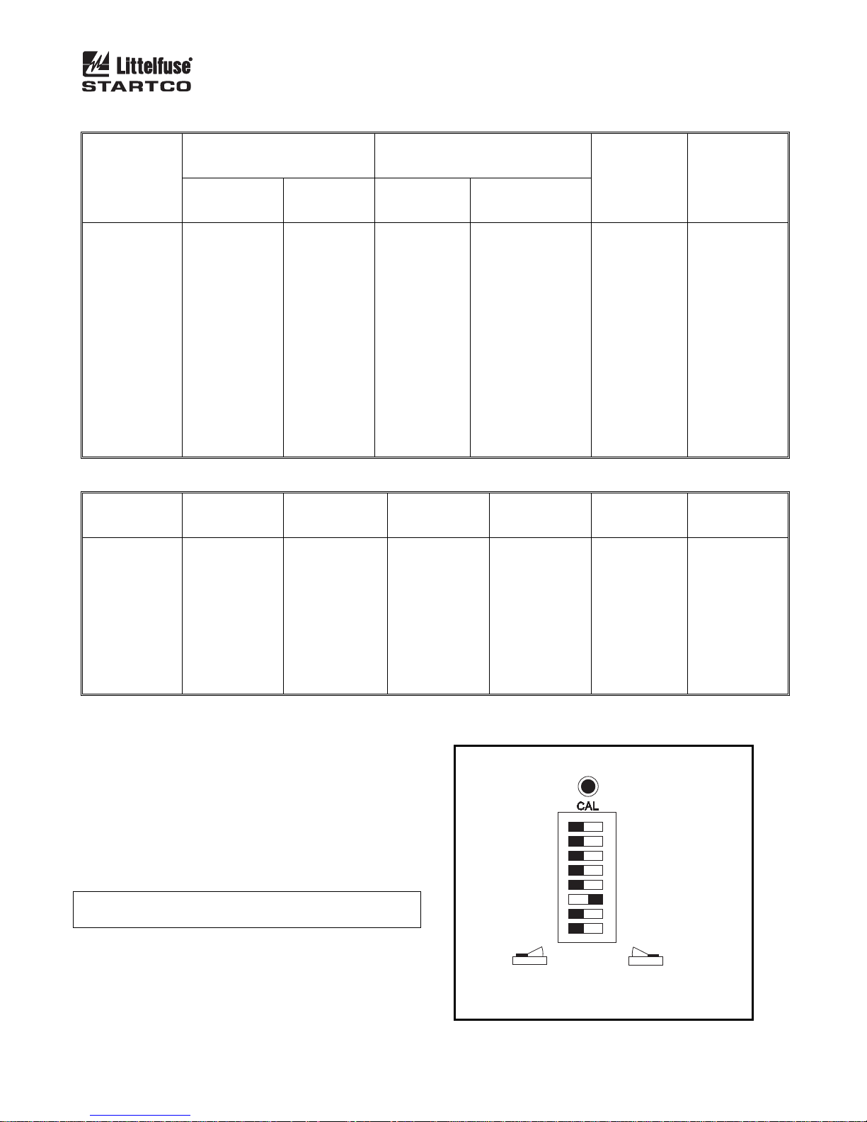
Eight configuration switches (S1 to S8) and a
calibration button are located behind the access cover on
the front panel. See Fig. 1.
NEUTRAL-GROUNDING
RESISTOR
CURRENT
(AMPERES)
5
5
5
5
15
15
15
15
15
15
25
25
25
25
25
RESISTANCE
(OHMS)
55
69
277
480
18
23
92
160
277
554
96
166
332
577
808
TABLE 2. GROUND-FAULT TRIP LEVELS FOR SELECTED CT’S
EFCT-x
5:0.05
(AMPERES)
SE-CS30-x
(AMPERES)
0.10
0.20
0.30
0.40
0.50
1.00
2.00
3.00
4.00
5.00
30:0.05
0.60
1.20
1.80
2.40
3.00
6.00
12.0
18.0
24.0
30.0
SENSING RESISTOR GROUND-
MODEL RESISTANCE
(SWITCH S5
SETTING)
ER-600VC
ER-600VC
ER-5KV
ER-5KV
ER-600VC
ER-600VC
ER-5KV
ER-5KV
ER-15KV
ER-15KV
ER-5KV
ER-15KV
ER-15KV
ER-25KV
ER-35KV
20 k
20 k
20 k
20 k
20 k
20 k
20 k
20 k
100 k
100 k
20 k
100 k
100 k
100 k
100 k
50:1
50:5
(AMPERES)
*
*
*
*
5
10
20
30
40
50
LATCHING GF TRIP
LATCHING RF TRIP
NOTE:
1. DEFAULT SETTINGS SHOWN.
100:1
100:5
(AMPERES)
*
*
*
8
10
20
40
60
80
100
K1 = TRIP
K1 FAIL-SAFE
20 kΩ
50 Hz
NOT USED
RUN
FIGURE 1. Configuration Switches.
FAULT
TRIP LEVEL
(AMPERES)
1.0
1.0
1.0
1.0
3.0
3.0
3.0
3.0
3.0
3.0
5.0
5.0
5.0
5.0
5.0
200:1
200:5
(AMPERES)
*
*
12
16
20
40
80
120
160
200
CALIBRATION BUTTON
K1 = PULSING
S1
K1 NON-FAIL-SAFE
S2
S3
NON-LATCHING GF TRIP
S4
NON-LATCHING RF TRIP
100 kΩ
S5
60 Hz
S6
S7
UPGRADE
S8
VN TRIP
LEVEL
(VOLTS)
60
100
340
800
60
100
340
800
170x5=850
340x5=1,700
800
170x5=850
340x5=1,700
800x5=4,000
1,200x5=6,000
400:1
400:5
(AMPERES)
*
16
24
36
40
80
160
240
320
400
Page 4
SE-330 Neutral-Grounding-Resistor Monitor Rev. 10-D-112913
2.1.5.1 RELAY K1 FUNCTION (S1)
Set switch S1 to K1 = TRIP to assign the trip function
to relay K1 and to activate switch S2. Relay K1 will
change state when a resistor-fault or ground-fault trip
occurs.
Set switch S1 to K1 = PULSING to configure relay K1
for pulsing operation. See Section 2.3.
2.1.5.2 T
RIP-RELAY MODE AND TRIP-MEMORY
MODE (S2)
Set switch S2 to select the operating mode of trip relay
K1. In the non-fail-safe mode, relay K1 energizes and its
contact closes when a trip occurs. The non-fail-safe mode
can be used to trip shunt-trip circuit breakers. In the
non-fail-safe mode, SE-330 trips are reset when supply
voltage is cycled.
In the fail-safe mode, relay K1 energizes and its contact
closes if there are no trips. Contacts open if there is a trip,
a loss of supply voltage, or a processor failure. In the
fail-safe mode, SE-330 trips are not reset when supply
voltage is cycled.
N
OTE: Switch S2 does not affect the operating modes of
relays K2, K3, and K4.
N
OTE: Switch S2 only affects relay K1 operating mode
when K1 is assigned the trip function (switch S1 set to K1
= TRIP). Trip memory is enabled when K1 is set to the
fail-safe mode, regardless of the switch S1 setting.
2.1.5.3 G
ROUND-FAULT-TRIP LATCH (S3)
Set switch S3 to select latching or non-latching groundfault-circuit operation. Non-latching operation defeats
ground-fault-trip memory. See Sections 2.1.5.2 and 2.4.
2.1.5.4 R
ESISTOR-FAULT-TRIP LATCH (S4)
Set switch S4 to select latching or non-latching
resistor-fault-circuit operation. Non-latching operation
defeats resistor-fault-trip memory. See Sections 2.1.5.2
and 2.4
2.1.5.5 S
ENSING-RESISTOR SELECTION (S5)
Set switch S5 to the resistance of the sensing resistor. For
the ER-600VC, ER-5KV, and ER-5WP, select 20 k. For
the ER-15KV, ER-25KV, and ER-35KV, select 100 k.
Switch S5 sets the resistor-fault trip value and the V
TRIP
N
LEVEL range. See Section 2.1.3.
2.1.5.6 F
REQUENCY (S6)
Set switch S6 to 50 or 60 Hz to tune the digital filter to
the line frequency of the monitored system.
2.1.5.7 U
PGRADE MODE (S8)
The microSD™ card is used for firmware upgrades.
See Section 4.1.2 for upgrade instructions.
OTE: An upgrade causes an SE-330 restart and this may
N
cycle the output relays.
2.2 CALIBRATION
The SE-330 measures the resistance change of the
NGR relative to the NGR-resistance value determined at
the time of calibration. When the resistance change is
greater than a threshold amount (500 Ω for 20-kΩ
systems, 2,500 Ω for 100-kΩ systems), a resistor-fault trip
occurs. Calibrate the SE-330 on new installations, if the
NGR is changed, or if the sensing resistor is changed.
N
OTE: If the SE-330 is not calibrated and is supplied
from the load side of the breaker (non-fail-safe mode),
calibrate within 12 seconds of power-up or it may trip and
interrupt its supply.
The CALIBRATION button is located behind the
access cover on the front panel, and it is recessed to
prevent inadvertent activation.
N
OTE: Calibration must be performed with the SE-330
connected to the sensing resistor and NGR of the installed
system.
To calibrate, press and hold the CALIBRATION button
until the green CALIBRATED LED turns off and returns
to on (if the LED is already off, press and hold until the
LED turns on). Calibration takes approximately two
seconds. If calibration is not successful, a resistor-fault
trip occurs, the RESISTOR FAULT TRIP LED will be
on, the CALIBRATED LED will be off, and the
DIAGNOSTIC LED will flash the calibration-error code.
See Section 2.8.
If latching resistor fault (switch S4) is selected, the
calibration-error code flashes until RESET is pressed
even if the CALIBRATED LED is on.
The calibration value is stored in non-volatile memory.
Page 5
SE-330 Neutral-Grounding-Resistor Monitor Rev. 10-D-112913
2.3 PULSING OPERATION
If switch S1 is set to K1 = PULSING, pulsing occurs
when terminal 16 is connected to terminal 17. Relay K1
operates at a 50% duty cycle and cycle time is adjustable
from 1.0 to 3.0 seconds. When terminals 16 and 17 are
not connected, K1 is not energized and its contact is open.
Relay K1 can be used to control a contactor rated for
use at the line-to-neutral voltage. The contactor causes
changes in neutral-to-ground resistance by adding or
shorting portions of the NGR. See Section 3.5. Pulsing
ground-fault current appears as zero-sequence current
upstream from the fault.
Pulsing ground-fault current is distinguishable from
charging current and noise, and it can be traced with a
clip-on ammeter or current probe. If pulsing current is
detected on a cable or conduit, the fault is downstream.
Systematic testing allows faults to be located without
isolating feeders or interrupting loads.
Stop pulsing when a fault is located.
2.4 T
RIP INDICATION AND RESET
Red LED's and indication relays indicate ground-fault
and resistor-fault trips. The indication relays K2 (GF) and
K3 (RF) operate in fail-safe or non-fail-safe mode. The
default is non-fail-safe mode. In this mode, the relays are
energized when a fault occurs. The relay mode setting is
stored in non-volatile memory and can be set using PCinterface SE-MON330 (version 3.0 or newer) software or
network communications.
When a trip occurs with latching operation selected, the
SE-330 remains tripped until reset with the front panel
button or the remote-reset input. See Sections 2.1.5.3 and
2.1.5.4. Terminals 15 and 16 are provided for remote reset
as shown in Fig. 3. The reset circuit responds only to a
momentary closure so that a jammed or shorted button
does not prevent a trip. The front-panel RESET button is
inoperative when terminal 15 is connected to terminal 16.
If non-latching operation is selected, trips and
corresponding indication automatically reset when the
fault clears and power-up trip memory is defeated even
when configuration switch S2 is set to fail-safe. The
maximum automatic reset time is 2.8 s.
The red DIAGNOSTIC LED annunciates latched
calibration-error and remote trips. See Section 2.8.
When supply voltage is applied with switch S2 set to
FAIL-SAFE, the SE-330 returns to its state prior to loss
of supply voltage unless switch S3 or S4 is set to nonlatching. When supply voltage is applied with switch S2
set to NON-FAIL-SAFE, SE-330 trips are reset. When a
local, remote, or network reset is issued, both trip LED's
will flash if they are off.
Resistor-fault-trip reset can take up to one second.
Resistor-fault trip-memory trip can take up to three
seconds after SE-330 power up.
2.5 R
EMOTE OPERATION
Relays K2 and K3 can be used for remote indication,
and terminals 15 and 16 are provided for remote reset.
RK-332 Remote Indication and Reset components are
shown in Fig. 19. Connect them as shown in Fig. 3.
RK-332 components are not polarity sensitive.
Indication relays can be set to fail-safe or non-fail-safe
operation using SE-MON330 or network
communications. The default mode is non-fail-safe. In
non-fail-safe mode, relays energize on fault.
Network-enabled SE-330’s can be remotely tripped and
reset by the network master. The red DIAGNOSTIC
LED indicates a network-initiated trip. See Section 2.8.
Refer to the appropriate SE-330 communications manual.
2.6 R
ELAY K1 LED
The yellow RELAY K1 LED follows the state of relay
K1 and is on when K1 is energized (contact closed).
2.7 U
NIT HEALTHY OUTPUT
UNIT HEALTHY relay K4 is energized when the
processor is operating. It can be ordered with N.O. or
N.C. contacts. See Section 7.
N
OTE: The K4 output changes state momentarily during
a processor reset.
N
OTE: K4-contact rating is 100 mA maximum.
IAGNOSTIC LED
2.8 D
The DIAGNOSTIC LED is used to annunciate trips
without individual LED indication. The number of short
LED pulses between pauses indicates the cause of the trip.
See Section 5.
Page 6
SE-330 Neutral-Grounding-Resistor Monitor Rev. 10-D-112913
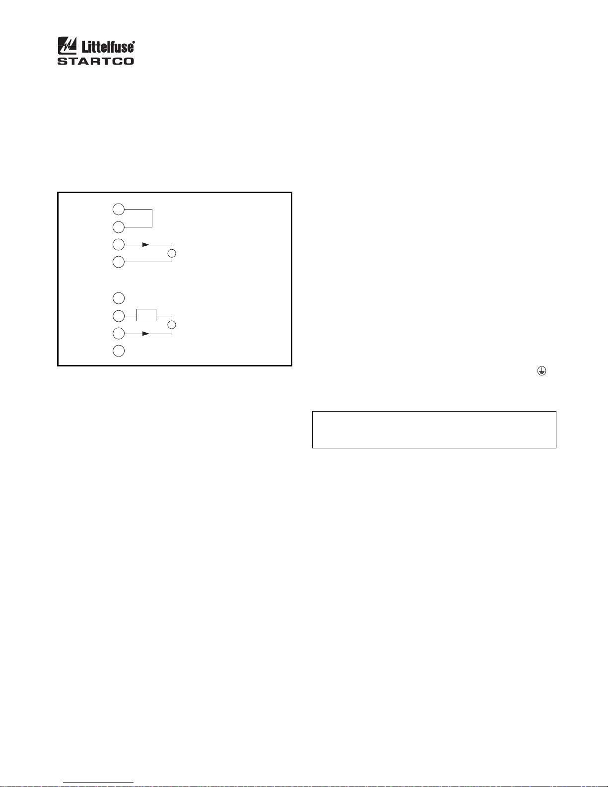
2.9 ANALOG OUTPUT
An isolated 4–20-mA output indicates NGR current
with full-scale output corresponding to the CT rating. An
internal 24-Vdc supply allows the analog output to be
connected as a self-powered output. Power from an
external supply is required for loop-powered operation.
See Fig. 2. A PGA-0520 analog meter can be panelmounted to display the NGR current. See Fig. 20 and
Section 7.
18
+24V
+
-
0V
+24V
+
-
0V
19
20
21
18
+
LOOP
SUPPLY
19
20
21
PGA-0520
-
PGA-0520
SELF-POWERED
LOOP POWERED
FIGURE 2. Analog-Output Connections.
3. INSTALLATION
3.1 SE-330
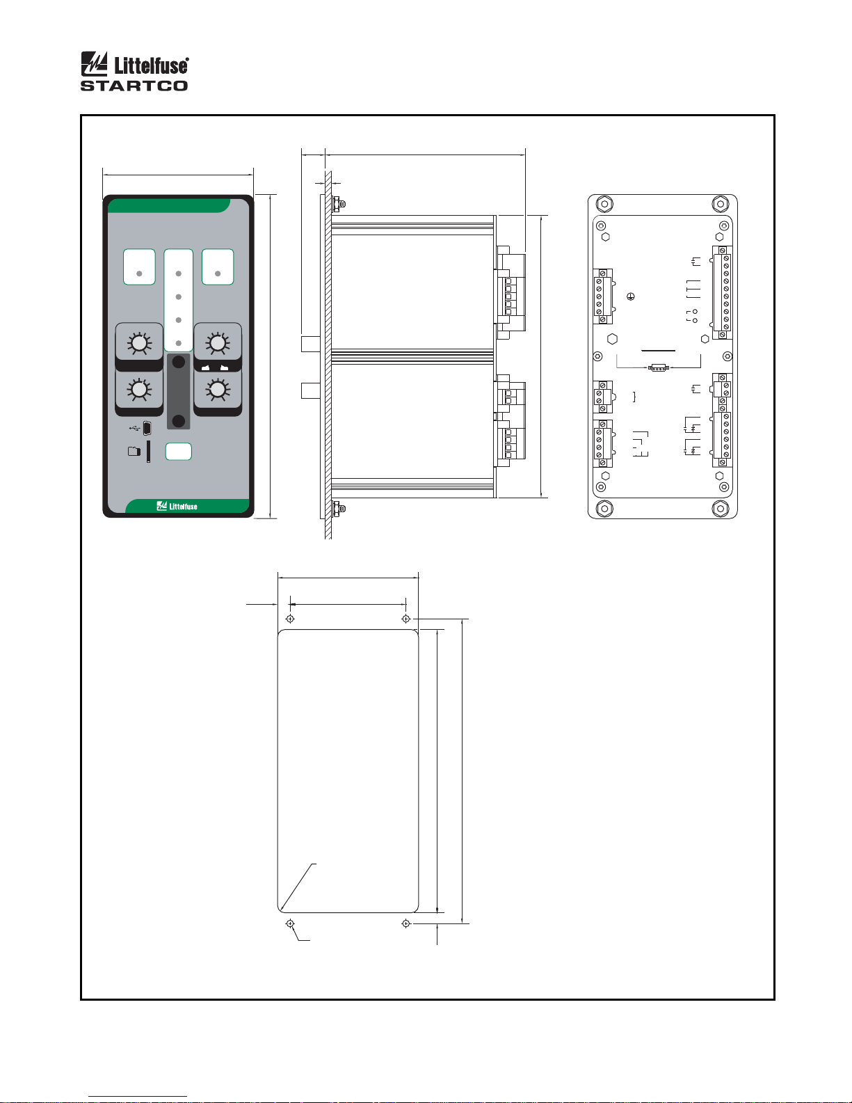
Outline and panel-cutout dimensions for the SE-330 are
shown in Fig. 4. To panel mount the SE-330, insert it
through the panel cutout and secure it with the four
included 8-32 locknuts and flat washers.
If an optional SE-IP65CVR-G Hinged Cover is used,
follow the included installation instructions. See Figs. 6
and 7.
All connections to the SE-330 are made with plug-in,
wire-clamping terminal blocks. Each plug-in terminal
block can be secured to the SE-330 by two captive screws
for reliable connections.
Outline dimensions and mounting details for surface
mounting the SE-330 are shown in Fig. 5. Fasten the
optional surface-mount adapter to the mounting surface
and make connections to the adapter terminal blocks.
Follow Fig. 5 instructions to mount or remove the SE-
330.
Ground terminal 7 (G) and connect terminal 6 (R) to
the sensing-resistor R terminal.
Use terminal 1 (L1) as the line terminal on ac systems,
or the positive terminal on dc systems. Use terminal 2
(L2/N) as the neutral terminal on ac systems or the
negative terminal on dc systems. Connect terminal 3 (
to ground. Connect terminal 4 (SPG) to terminal 5
(SPGA).
N
OTE: Disconnect terminal 1 (L1) and terminal 2 (L2/N)
before performing dielectric strength testing of the control
panel.
)
Page 7
SE-330 Neutral-Grounding-Resistor Monitor Rev. 10-D-112913
TRANSFORMER
OR GENERATOR
NOTE 1 NEUTRAL
NOTE 16
NOTE 12
XXX:1
OR
8
9
S1
XXX:5
10
5C
11
8910
S
SE-330
ALTERNATE CT
CONNECTIONS
REMOTE
RESET
PULSE
ENABLE
L/+ SUPPLY
NOTE 14
OPTIONAL
NETWORK COM
NOTE 10
1
L1
22
26
29
12
UNIT HEALTHY
NC
14
ANALOG OUTPUT
15
RESET
16
PULSE ENABLE
17
3
4
SPG
5
SPGA
R
R
R
G
Y
G
SE-330
INDICATION
GROUND-FAULT
TRIP
RESISTORFAULT TRIP
DIAGNOSTIC
CALIBRATED
RELAY K1
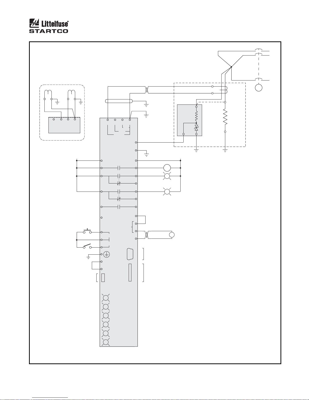
FIGURE 3. SE-330 Connection Diagram.
1
EFCT
NOTE 6
K1
K2
K3
K4
NOTE 7
POWER
1 A
NOTES 11 & 12
ER-SERIES
N/- SUPPLY
C
PGA-0520
SENSING
RESISTOR
11
5
C
5 A
6
R
7
G
2
GF
RF
L2/N
+24V
23
24
25
27
28
13
18
19
+
20
-
21
0V
NOTE 13 & 14
NOTE 8
NOTE 15
GROUND
FAULT
RESISTOR
FAULT
NOTE 2
EFCT-X
OR
SE-CS30-X
NOTE 3
N
NGR
NOTE 4
G
R
NOTE 5
C
NOTES:
1. USE SEPARATE LUG TO CONNECT SENSING RESISTOR TERMINAL N TO NEUTRAL.
2. LOCATE THESE COMPONENTS NEAR
TRANSFORMER OR GENERATOR.
3. ALTERNATE SENSING-RESISTOR
TERMINAL-N CONNECTION. THE NEUTRAL
CONNECTION IS NOT MONITORED.
4. VOLTAGE BETWEEN SENSING-RESISTOR
TERMINALS R AND G IS LIMITED TO 100 V BY
INTERNAL CLAMP.
5. SEE SECTION 3.4 FOR ISOLATED-GROUND
CONNECTION.
6. RELAY CONTACTS SHOWN WITH SE-330
DE-ENERGIZED.
USB PORT
NOTE 9
7. OPTIONAL N.C. K4 AVAILABLE.
8. LOOP-POWERED CONNECTION USES
MICRO SD
SLOT
TERMINALS 19 AND 20 ONLY.
9. MINI B USB DEVICE CONNECTOR.
10. REFER TO APPROPRIATE SE-330
COMMUNICATIONS INTERFACE MANUAL.
11. TWO-CONDUCTOR TWISTED CABLE
REQUIRED, SHIELDED RECOMMENDED.
12. CT CONNECTION IS NOT POLARITY
SENSITIVE.
13. CONNECT CONTACTS K1, K2, K3, AND K4
AS REQUIRED FOR PROTECTION,
INDICATION, AND CONTROL.
14. EXTERNAL LIGHTS AND SWITCHES NOT
INCLUDED WITH SE-330.
15. SELF-POWERED 4-20 mA OUTPUT.
16. TYPICAL TRIPPING SYSTEM.
Page 8
SE-330 Neutral-Grounding-Resistor Monitor Rev. 10-D-112913
98.3
(3.87)
LITTELFUSE STARTCO
MONITOR
GROUND
FAULT
DIAGNOSTIC
TRIP
CALIBRATED
RELAY K1
20
10
40
8
60
680
4
GF TRIP LEVEL
(% CT RATING)
0.5
0.4
0.3
0.2
0.1
GF TRIP TIME (s)
POWER
100
MEM2
0.7
1.0
CAL
2.0
3.0
5.0
10.0
RESET
FRONT VIEW
SE-330NEUTRAL-GROUNDING-RESISTOR
RESISTOR
FAULT
TRIP
200
170
340
130
800
100 1200
60
1700
200020
V TRIP LEVELN
20 K
Ω
()
S5
Vx 1
N
2.0
1.8
2.2
1.6
1.4
1.2
1.0
PULSE PERIOD (s)
212.6
Ω
100 K
Vx 5
N
2.4
2.6
2.8
3.0
(8.37)
16.0
(0.63)
132.0
(5.20)
PANEL THICKNESS
1.6 (0.06) TO 4.8 (0.19)
SIDE VIEW
185.4
(7.30)
UNIT
K4
HEALTHY
-
1
L1
-
2
L2/N
-
3
-
4
SPG
-
SPGA
5
DISENGAGE CAPTIVE RETAINING
SCREWS BEFORE REMOVING
PLUG-IN TERMINAL BLOCKS
-
R
6
-
G
7
-
S
8
-
1
9
-
5
10
5
A
-
C
11
PULSE ENABLE
ANALOG OUTPUT
ATTENTION
SENSING
RESISTOR
GROUND
E
F
RESISTOR
C
1
T
A
FAULT
FAULT
RESET
+
K2
K3
REAR VIEW
12
13
-
14
NC
15
16
17
-
24V
18
-
+
19
20
-
-
-
21
0V
22
K1
23
24
25
26
27
28
29
8.2
(0.32)
92.7
(3.65)
76.2
(3.00)
R=4.8 (0.19)
MAXIMUM
4.75 (0.187) DIA
4 LOCATIONS
186.0
7. 0
200.0
(7.32)
(0.28)
NOTES:
1. DIMENSIONS IN MILLIMETRES (INCHES).
(7.87)
PANEL-MOUNT CUTOUT
FIGURE 4. SE-330 Outline and Panel-Mounting Details.
 Loading...