

Page 1
QxxxxLTx Series
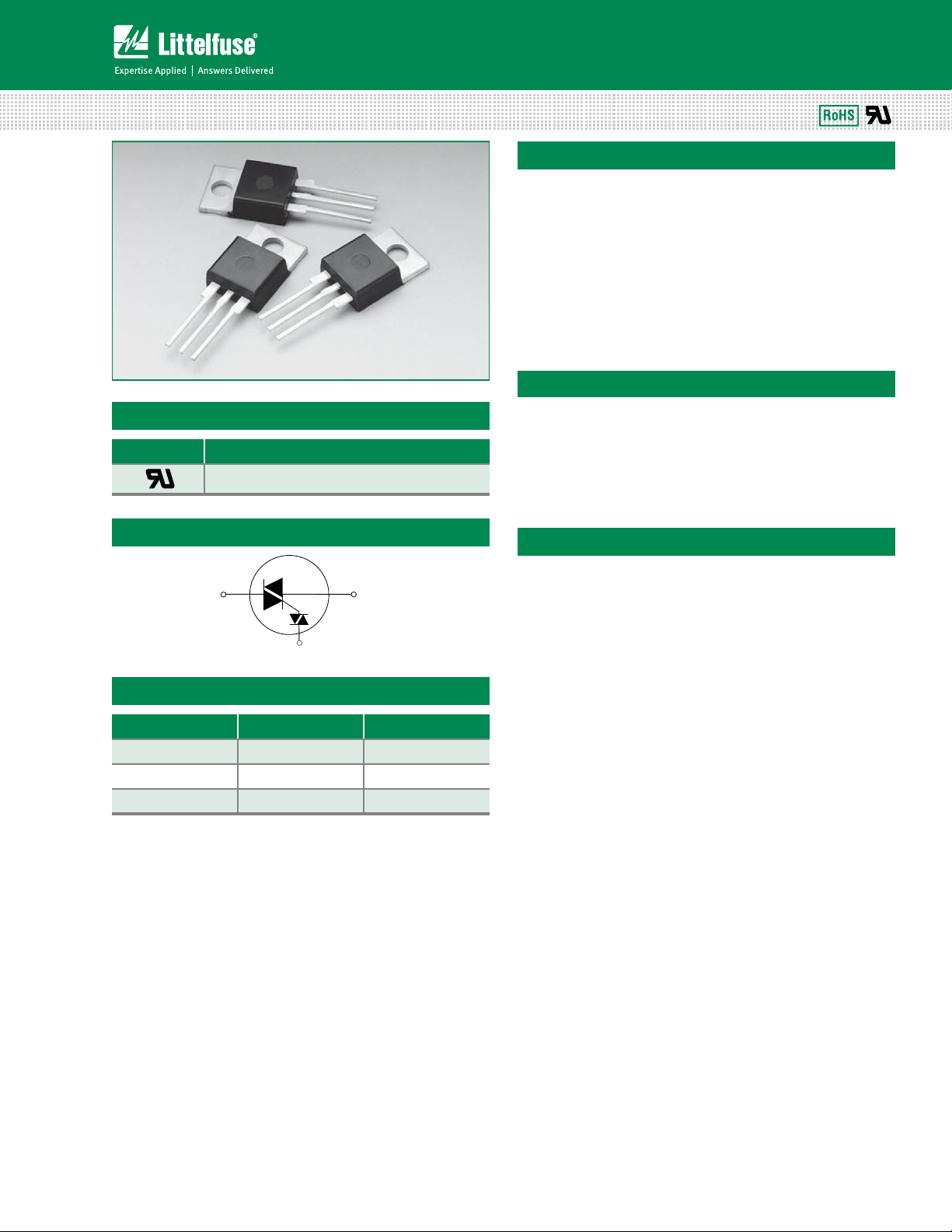
Teccor® brand Thyristors
4 / 6 / 8 / 10 / 15 Amp Quadracs
Description
The Quadrac is an internally triggered Triac designed for
AC switching and phase control applications. It is a Triac
and DIAC in a single package, which saves user expense
by eliminating the need for separate Triac and DIAC
components.
Standard type devices normally operate in Quadrants I & III
triggered from AC line.
Alternistor type Quadracs are used in circuits requiring high
dv/dt capability.
Features & Benefits
Agency Approval
Agency Agency File Number
®
L Package : E71639
Schematic Symbol
MT2 MT1
T
Main Features
Symbol Value Unit
I
T(RMS)
V
/ V
DRM
DIAC V
RRM
BO
4 to 15 A
400 to 600 V
33 to 43 V
t3P)4$PNQMJBOU
t(MBTToQBTTJWBUFE
t4VSHFDBQBCJMJUZVQUP
200 A
junctions
t7PMUBHFDBQBCJMJUZVQUP
600 V
Applications
Excellent for AC switching and phase control applications
such as lighting and heating. Typical applications are AC
solid-state switches, light dimmers, power tools, home/
brown goods and white goods appliances.
Alternistor Quadracs (no snubber required) are used in
applications with extremely inductive loads requiring
highest commutation performance.
Internally constructed isolated package is offered for ease
of heat sinking with highest isolation voltage.
QxxxxLTx Series
169
Specifications are subject to change without notice.
©2013 Littelfuse, Inc
Revised: 09/23/13
Page 2

Absolute Maximum Ratings
Teccor® brand Thyristors
4 / 6 / 8 / 10 / 15 Amp Quadracs
Value
Symbol Parameter
Qxx04LT: TC = 95°C
I
T(RMS)
RMS forward current
Qxx06LT/Qxx08LT/Qxx10LT: TC = 90°C
Qxx15LT: TC = 80°C
single half cycle; f = 50Hz;
T
(initial) = 25°C
I
TSM
2
tI
I
Peak non-repetitive surge current
2
t value for fusing tp = 8.3ms 12.5 26.5 41 60 166 A2s
J
single half cycle; f = 60Hz;
(initial) = 25°C
T
J
di/dt Critical rate-of-rise of on-state current f = 60Hz; T
I
GM
T
stg
T
J
Note: xx = voltage
Operating junction temperature range -40 to 125 °C
Electrical Characteristics (T
Peak gate current TJ = 125°C 1.5 A
Storage temperature range -40 to 150 °C
= 25°C, unless otherwise specified) – Standard Quadrac
J
Symbol Test Conditions
I
H
dv/dt
dv/dt(c) di/dt(c) = 0.54 x I
t
gt
(1) Reference test circuit in figure 10 and waveform in figure 11; CT = 0.1F with 0.1s rise time.
Note: xx = voltage
IT = 200mA (initial) MAX. 40 50 60 60 70 mA
V
= V
; gate open; TJ=100°C MIN.
D
DRM
= V
V
; gate open; TJ=125°C MIN.
D
DRM
/ ms; TJ = 125°C MIN. 3 4 V/s
T(rms)
400V 75 150 175 200 300
600V 50 125 150 175 200
400V 50 100 120 150 200
600V 50 85 100 120 150
(note 1) TYP. 3 s
Unit
Qxx04LT
Qxx06LT /
Qxx08LT /
Qxx06LTH
Qxx08LTH
Qxx10LT /
Qxx10LTH
Qxx15LT /
Qxx15LTH
4681015A
46 65 83 100 167
55 80 100 120 200
=125°C 50 70 100 A/µs
J
Value
Unit
Qxx04LT
Qxx06LT
Qxx08LT
Qxx10LT
Qxx15LT
V/s
A
Electrical Characteristics (T
= 25°C, unless otherwise specified) – Alternistor Quadrac
J
Symbol Test Conditions
I
H
IT = 20mA (initial) MAX. 50 50 60 70 mA
V
= V
; gate open; TJ=100°C MIN.
D
DRM
dv/dt
V
= V
; gate open; TJ=125°C MIN.
D
DRM
dv/dt(c) di/dt(c) = 0.54 x I
t
gt
(1) Reference test circuit in figure 10 and waveform in figure 11; CT = 0.1F with 0.1s rise time.
Note: xx = voltage
QxxxxLTx Series
(note 1) TYP. 3 s
/ ms; TJ = 125°C MIN. 25 30 V/s
T(rms)
170
Value
Qxx06LTH
Qxx08LTH
Qxx10LTH
400V 575 925
600V 425 775
400V 450 700
600V 350 600
Specifications are subject to change without notice.
Unit
Qxx15LTH
V/s
©2013 Littelfuse, Inc
Revised: 09/23/13
Page 3

Teccor® brand Thyristors
4 / 6 / 8 / 10 / 15 Amp Quadracs
Trigger DIAC Specifications
Symbol Test Conditions Value Unit
∆V
BO
V
BO
[∆V±] Dynamic Breakback Voltage, forward and reverse (note 1) MIN. 5 V
I
BO
C
T
(1) Reference test circuit in figure 10 and waveform in figure 11.
Static Characteristics
Symbol Test Conditions Value Unit
V
TM
/ I
I
DRM
RRM
Breakover Voltage Symmetry MAX. 3 V
Breakover Voltage, forward and reverse
MIN. 33
MAX. 43
Peak Breakover Current MAX. 25 uA
Trigger Firing Capacitance MAX. 0.1 µF
IT = 1.41 x I
V
/ V
DRM
A; tp = 380s MAX. 1.6 V
T(rms)
TJ = 25°C
RRM
= 100°C 500
J
= 125°C 2000
T
J
MAX.
10
V
µAT
Thermal Resistances
Symbol Parameter Value Unit
Qxx04LT 3.6
R
(J-C)
R
(J-A)
Note : xx = voltage
Junction to case (AC)
Junction to ambient 50 °C/W
Qxx06LT /
Qxx06LTH
Qxx08LT /
Qxx08LTH
Qxx10LT /
Qxx10LTH
Qxx15LT /
Qxx15LTH
3.3
2.8
2.6
2.1
°C/W
QxxxxLTx Series
171
Specifications are subject to change without notice.
©2013 Littelfuse, Inc
Revised: 09/23/13
Page 4

Teccor® brand Thyristors
4 / 6 / 8 / 10 / 15 Amp Quadracs
Figure 1: Normalized DC Holding Current
vs. Junction Temperature
2.0
1.5
= 25°C)
J
(T
H
1.0
/I
H
Ratio of I
0.5
0.0
-40 -15 10 35 60 85 110
Junction Temperature (T
) -- °C
Figure 3: On-State Current vs. On-State Voltage
(Typical) (6A to 15A)
50
45
TJ = 25°C
40
) – Amps
T
35
30
25
20
15
10
5
Instantaneous On-state Current (i
0
0.7 0.8 0.9 1.0 1.1 1.2 1.3 1.4 1.5 1.6 1.7
Instantaneous On-state Voltage (vT) – Volts
Qxx15LT
Qxx15LTH
Qxx06LT/Qxx06LTH
Qxx08LT/Qxx08LTH
Qxx10LT/Qxx10LTH
Figure 2: On-State Current vs. On-State Voltage
(Typical) (4A)
16
TJ = 25°C
14
) – Amps
T
12
10
8
6
4
2
Instantaneo us On-state Curr ent (i
0
0.7 0.8 0.9 1.0 1.1 1.2 1.3 1.4 1.5 1.6
Qxx04LT
Instan taneous On-state V oltage (vT) – Vol ts
Figure 4: Power Dissipation vs. RMS On-State
Current (Typical) (4A)
4.0
3.5
3.0
2.5
2.0
] - (Watts)
D(AV)
[P
1.5
1.0
Average On-S tate Power Dissipation
0.5
0.0
0.0 0.5 1.0 1. 5 2.0 2.5 3.0 3.5 4. 0
RMS On -State Current [I
Qxx04LT
CURRENT WAVEFORM: Sinusoidal
LOAD: Resistive or Inductive
CONDUCTION ANGLE: 360°
] - (Amps)
T(RMS)
Figure 5: Power Dissipation vs. RMS On-State Current
(Typical) (6A to 15A)
18
16
14
12
10
] - (Watts)
8
D(AV)
[P
6
4
2
Average On -State P ower Dissipation
0
024 6810121
QxxxxLTx Series
Qxx06LT/Qxx06LTH
Qxx08LT/Qxx08LTH
Qxx10LT/Qxx10LTH
RMS On -Sta te Curre nt [I
CURRENT WAVEFORM: Sinusoidal
LOAD: Resistive or Inductive
CONDUCTION ANGLE: 360°
] - (Amps)
T(RMS )
Qxx15LT
Qxx15LTH
4 16
Figure 6: Maximum Allowable Case Temperature
vs. RMS On-State Current
130
CURRENT WAVEFORM: Sinusoidal
LOAD: Resistive or Inductive
CONDUCTION ANGLE: 180°
Qxx10LT
Qxx10LTH
] - Amps
T(RMS )
Specifications are subject to change without notice.
172
120
110
) - °C
100
C
(T
Qxx04LT
90
Qxx06LT
80
Qxx06LTH
Qxx08LT
Qxx08LTH
Maxim um Allowabl e Case Temperature
70
0246810121
RMS On -Sta te Curre nt [I
Qxx15LT
Qxx15LTH
416
©2013 Littelfuse, Inc
Revised: 09/23/13
Page 5

Teccor® brand Thyristors
Typical (35V Device)
4 / 6 / 8 / 10 / 15 Amp Quadracs
Figure 7: Surge Peak On-State Current vs. Number of Cycles
1000
Qxx15LT/Qxx15LTH
100
) – Amps
TSM
10
Peak Surge (Non-repetitive)
On-state Current (I
Qxx06LT/Qxx06LTH
1
1 10 100 1000
Qxx10LT/Qxx10LTH
Qxx04LT
Surge Current Duration -- Full Cycles
Note: xx = voltage
Figure 8: DIAC VBO Change vs. Junction Temperature
6%
4%
2%
0%
Change -- %
-2%
BO
V
-4%
-6%
-8%
-40 -20 0 20 40 60 80 100 120 140
Junction Tempera ture (TJ) -- °C
Qxx08LT/Qxx08LTH
Supply Frequency: 60Hz Sinusoidal
Load: Resistive
RMS On-State Current: [I
Value at Specific Case Temperature
Notes:
1. Gate control may be lost during and immediately
following surge current interval.
2. Overload may not be repeated until junction
temperature has returned to steady-state
rated value.
Figure 9: Test Circuit
R
L
120 V
60 Hz
V
C
]: Maximum Rated
T(RMS)
D.U.T.
MT2
T
C
T
= 0.1 μF
MT1
Figure 10: Test Circuit Waveform
V
C
+V
QxxxxLTx Series
BO
0
-V
BO
I
L
+I
PK
0
-I
PK
Typical pulse base width is 10μs
ΔV+
Figure 11: Peak Output Current vs Triggering
Capacitance (Per Figure 9)
300
250
) – mA
t
ΔV-
t
173
PK
200
150
100
Peak Output Current (I
50
0
0.1 0.2 0.3 0.4 0.5 0.6 0.7 0.8 0.9 1.0
Triggering Capacitance (CT) – μF
Specifications are subject to change without notice.
©2013 Littelfuse, Inc
Revised: 09/23/13
Page 6

Soldering Parameters
R
do
Teccor® brand Thyristors
4 / 6 / 8 / 10 / 15 Amp Quadracs
Reflow Condition 1Co'SFFBTTFNCMZ
Pre Heat
- Temperature Min (T
- Temperature Max (T
) 150°C
s(min)
) 200°C
s(max)
- Time (min to max) (ts) oTFDT
Average ramp up rate (Liquidus Temp)
(TL) to peak
T
to TL - Ramp-up Rate 5°C/second max
S(max)
Reflow
- Temperature (TL) (Liquidus) 217°C
- Temperature (tL) oTFDPOET
Peak Temperature (TP) 260°C
Time within 5°C of actual peak
Temperature (tp)
5°C/second max
+0/-5
oTFDPOET
Ramp-down Rate 5°C/second max
Time 25°C to peak Temperature (TP) 8 minutes Max.
Do not exceed 280°C
Physical Specifications
Terminal Finish 1005 Matte Tin-plated
Body Material
UL Recognized epoxy meeting
flammability classification 94v-0
Lead Material Copper Alloy
Design Considerations
Careful selection of the correct device for the application’s
operating parameters and environment will go a long way
toward extending the operating life of the Thyristor. Good
design practice should limit the maximum continuous
current through the main terminals to 75% of the device
rating. Other ways to ensure long life for a power discrete
semiconductor are proper heat sinking and selection of
voltage ratings for worst case conditions. Overheating,
overvoltage (including dv/dt), and surge currents are
the main killers of semiconductors. Correct mounting,
soldering, and forming of the leads also help protect
against component damage.
t
T
P
T
L
T
S(max)
Temperature
T
S(min)
25
Ramp-up
Ramp-up
PreheatPreheat
t
S
time to peak temperature
P
t
L
Ramp-down
amp-
Time
Environmental Specifications
Test
High Temperature
Voltage Blocking
Temperature Cycling
Biased Temperature &
Humidity
High Temp Storage
Low-Temp Storage -40°C, 1008 hours
Thermal Shock
Autoclave
(Pressure Cooker Test)
Resistance to
Solder Heat
Solderability ANSI/J-STD-002, Category 3, Test A
Lead Bend MIL-STD-750: Method 2036, Condition E
Specifications and Conditions
MIL-STD-750: Method 1040, Condition A
Rated V
hours
(VAC-peak), 125°C, 1008
DRM
MIL-STD-750: Method 1051
-40°C to 150°C, 15-minute dwell,
100 cycles
EIA/JEDEC: JESD22-A101
320VDC, 85°C, 85%RH, 1008 hours
MIL-STD-750: Method 1031
150°C, 1008 hours
MIL-STD-750: Method 1056
0°C to 100°C, 5-minute dwell,
10-second transfer, 10 cycles
EIA/JEDEC: JESD22-A102
121°C, 100%RH, 2atm, 168 hours
MIL-STD-750: Method 2031
260°C, 10 seconds
QxxxxLTx Series
174
Specifications are subject to change without notice.
©2013 Littelfuse, Inc
Revised: 09/23/13
Page 7

Teccor® brand Thyristors
4 / 6 / 8 / 10 / 15 Amp Quadracs
Dimensions — TO-220AB (L-Package) — Isolated Mounting Tab
T
MEASURING POINT
C
E
C
D
G
A
B
F
R
L
H
K
J
MT1
MT2
T (Trigger)
O
P
AREA (REF.)
2
0.17 in
N
M
Note: Maximum torque
to be applied to mounting tab
is 8 in-lbs. (0.904 Nm).
8.13
.320
13.36
.526
7. 0 1
.276
Dimension
Inches Millimeters
Min Max Min Max
A 0.380 0.420 9.65 10.67
B 0.105 0.115 2.67 2.92
C 0.230 0.250 5.84 6.35
D 0.590 0.620 14.99 15.75
E 0.142 0.147 3.61 3.73
F 0.110 0.130 2.79 3.30
G 0.540 0.575 13.72 14.61
H 0.025 0.035 0.64 0.89
J 0.195 0.205 4.95 5.21
K 0.095 0.105 2.41 2.67
L 0.060 0.075 1.52 1.91
M 0.085 0.095 2.16 2.41
N 0.018 0.024 0.46 0.61
O 0.178 0.188 4.52 4.78
P 0.045 0.060 1.14 1.52
R 0.038 0.048 0.97 1.22
Product Selector
Part Number
400V 600V 800V 1000V
Qxx04LT X X Quadrac TO-220L
Qxx06LT X X Quadrac TO-220L
Qxx06LTH X X Alternistor Quadrac TO-220L
Qxx08LT X X Quadrac TO-220L
Qxx08LTH X X Alternistor Quadrac TO-220L
Qxx10LT X X Quadrac TO-220L
Qxx10LTH X X Alternistor Quadrac TO-220L
Qxx15LT X X Quadrac TO-220L
Qxx15LTH X X Alternistor Quadrac TO-220L
Note: xx = Voltage
Voltage
Type Package
QxxxxLTx Series
175
Specifications are subject to change without notice.
©2013 Littelfuse, Inc
Revised: 09/23/13
Page 8

Teccor® brand Thyristors
4 / 6 / 8 / 10 / 15 Amp Quadracs
Packing Options
Part Number Marking Weight Packing Mode Base Quantity
Qxx04LT
Qxx04LTTP Qxx04LT 2.2 g Tube 500 (50 per tube)
Qxx06LT Qxx06LT 2.2 g Bulk 500
Qxx06LTTP Qxx06LT 2.2 g Tube 500 (50 per tube)
Qxx06LTH Qxx06LTH 2.2 g Bulk 500
Qxx06LTHTP Qxx06LTH 2.2 g Tube 500 (50 per tube)
Qxx08LT Qxx08LT 2.2 g Bulk 500
Qxx08LTTP Qxx08LT 2.2 g Tube 500 (50 per tube)
Qxx08LTH Qxx08LTH 2.2 g Bulk 500
Qxx08LTHTP Qxx08LTH 2.2 g Tube 500 (50 per tube)
Qxx10LT Qxx10LT 2.2 g Bulk 500
Qxx10LTTP Qxx10LT 2.2 g Tube 500 (50 per tube)
Qxx10LTH Qxx10LTH 2.2 g Bulk 500
Qxx10LTHTP Qxx10LTH 2.2 g Tube 500 (50 per tube)
Qxx15LT Qxx15LT 2.2 g Bulk 500
Qxx15LTTP Qxx15LT 2.2 g Tube 500 (50 per tube)
Qxx15LTH Qxx15LTH 2.2 g Bulk 500
Qxx15LTHTP Qxx15LTH 2.2 g Tube 500 (50 per tube)
Note: xx = Voltage
Qxx04LT 2.2 g Bulk 500
DEVICE TYPE
Q: Quadrac
VOLTAGE RATING
40: 400V
60: 600V
CURRENT RATING
04: 4A
06: 6A
08: 8A
10: 10A
15: 15A
Q 60 10 L T H 56
PACKAGE TYPE
L: TO-220 (Isolated)
LEAD FORM DIMENSIONS
xx: Lead Form Option
TRIAC TYPE
(blank): Standard Triac
H: Alternistor Triac
Trigger
T: Internal Diac (33V – 43V)
Part Marking SystemPart Numbering System
TO-220 AB - (L Package)
Q6010LTH
YMXXX
®
Date Code Marking
Y:Year Code
M: Month Code
XXX: Lot Trace Code
QxxxxLTx Series
176
Specifications are subject to change without notice.
©2013 Littelfuse, Inc
Revised: 09/23/13
 Loading...