

Page 1
Teccor® brand Thyristors
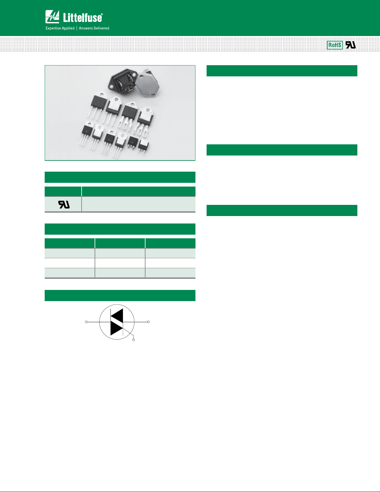
25 Amp Standard & Alternistor (High Commutation) Triacs
Qxx25xx & Qxx25xHx Series
Description
25 Amp bi-directional solid state switch series is designed
for AC switching and phase control applications such as
motor speed and temperature modulation controls, lighting
controls, and static switching relays.
Standard type devices normally operate in Quadrants I & III
triggered from AC line.
Alternistor type devices only operate in quadrants I, II, & III
and are used in circuits requiring high dv/dt capability.
Features & Benefits
Agency Approval
Agency Agency File Number
®
TO-220L, TO-218K, TO-218J &
Fastpak Packages: E71639
Main Features
Symbol Value Unit
I
T(RMS)
V
DRM/VRRM
I
GT
25 A
1000 V
50 to 80 mA
Schematic Symbol
MT2 MT1
t3P)4DPNQMJBOU
t(MBTToQBTTJWBUFE
t4VSHFDBQBCJMJUZVQ
to 250 A
junctions
t7PMUBHFDBQBCJMJUZVQ
to 1000 V
Applications
Excellent for AC switching and phase control applications
such as heating, lighting, and motor speed controls.
Typical applications are AC solid-state switches, industrial
power tools, exercise equipment, white goods and
commercial appliances.
Alternistor Triacs (no snubber required) are used in
applications with extremely inductive loads requiring
highest commutation performance.
Internally constructed isolated packages are offered for
ease of heat sinking with highest isolation voltage.
Qxx25xx & Qxx25xHx Series
G
131
Specifications are subject to change without notice.
©2013 Littelfuse, Inc
Revised: 09/23/13
Page 2

Teccor® brand Thyristors
25 Amp Standard & Alternistor (High Commutation) Triacs
Absolute Maximum Ratings – Standard Triac
Symbol Parameter Test Conditions Value Unit
Qxx25R5
I
T(RMS)
RMS on-state current
Qxx25N5
Qxx25P5 T
Qxx25R5
Qxx25N5
I
TSM
Peak non-repetitive surge current
Qxx25P5
Qxx25R5
2
I
tI
2
t Value for fusing
Qxx25N5
Qxx25P5 260
di/dt Critical rate-of-rise of on-state current f = 60Hz; T
I
P
T
GTM
G(AV)
stg
Peak gate current
Average gate power dissipation
T
= 125°C
J
T
= 125°C
J
Storage temperature range -40 to 125 °C
Qxx25R5
T
J
Operating junction temperature range
Qxx25N5
Qxx25P5 -25 to 125
= 85°C
T
C
= 57°C
C
full cycle; f = 50Hz;
T
(initial) = 25°C
J
full cycle; f = 60Hz;
T
(initial) = 25°C
J
full cycle; f = 50Hz;
T
(initial) = 25°C
J
full cycle; f = 60Hz;
TJ (initial) = 25°C
tp = 8.3ms
=125°C 100 A/s
J
25 A
167
200
220
250
166
2A
0.5 W
-40 to 125
A
A2s
°C
Absolute Maximum Ratings – Alternistor Triac
Symbol Parameter Test Conditions Value Unit
Qxx25LH5
Qxx25L6
Qxx25K6
I
T(RMS)
RMS on-state current
Qxx25J6
Qxx25RH5
Qxx25NH5
Qxx25R6
Qxx25NH6
full cycle; f = 50Hz;
T
(initial) = 25°C
I
TSM
2
tI
I
Peak non-repetitive surge current
2
t Value for fusing tp = 8.3ms 260 A2s
J
full cycle; f = 60Hz;
T
(initial) = 25°C
J
di/dt Critical rate-of-rise of on-state current f = 60Hz; T
I
GTM
P
G(AV)
T
stg
T
J
Note: xx = voltage
Operating junction temperature range -40 to 125 °C
Peak gate current TJ = 125°C 2 A
Average gate power dissipation TJ = 125°C 0.5 W
Storage temperature range -40 to 125 °C
TC = 65°C
TC = 85°C
25 A
TC = 95°C
208
250
=125°C 100 A/s
J
A
Qxx25xx & Qxx25xHx Series
132
Specifications are subject to change without notice.
©2013 Littelfuse, Inc
Revised: 09/23/13
Page 3

Teccor® brand Thyristors
25 Amp Standard & Alternistor (High Commutation) Triacs
Electrical Characteristics (T
= 25°C, unless otherwise specified) — Standard Triac
J
Value
Symbol Test Conditions Quadrant
I
GT
VD = 12V; RL = 60
V
GT
V
GD
I
H
VD = V
; RL = 3.3 k ; TJ = 125°C ALL MIN. 0.2 V
DRM
IT = 400mA (initial) MAX. 100 50 mA
*o**o*** MAX. 50
IV TYP. 120
*o**o*** MAX. 1.3
IV TYP. 2.5
400V
V
= V
dv/dt
; Gate Open; TJ = 125°C
D
DRM
= V
V
; Gate Open; TJ = 100°C
D
DRM
600V 225 475
800V 200 400
1000V 200 —
MIN.
Qxx25R5
Qxx25N5
275 —
Qxx25P5
Unit
mA
V
V/s
(dv/dt)c (di/dt)c = 13.3 A/ms; TJ = 125°C MIN. 5 V/s
t
gt
Electrical Characteristics (T
IG = 2 x IGT; PW = 15µs; IT = 35.4 A
= 25°C, unless otherwise specified) — Alternistor Triac
J
TYP. 4 3 s
Value
Qxx25R6
Symbol Test Conditions Quadrant
Qxx25RH5
Qxx25LH5
Qxx25NH5
Qxx25L6
Qxx25NH6
Qxx25K6
Unit
Qxx25J6
I
GT
V
GT
V
GD
I
H
dv/dt
VD = 12V; RL = 60
VD = V
; RL = 3.3 k ; TJ = 125°C *o**o*** MIN. 0.2 V
DRM
IT = 400mA (initial) MAX. 50 100 mA
V
= V
; Gate Open; TJ = 125°C
D
DRM
= V
V
; Gate Open; TJ = 100°C
D
DRM
(dv/dt)c (di/dt)c = 13.3 A/ms; T
t
gt
IG = 2 x IGT; PW = 15µs; IT = 35.4 A
= 125°C MIN. 20 30 V/s
J
*o**o*** MAX. 50 80 mA
*o**o*** MAX. 1.3 V
400V
600V 500 600
800V 400 475
MIN.
575 600
V/s
1000V — 400
TYP. 3 5 s
Static Characteristics
Symbol Test Conditions
V
TM
I
/ I
DRM
Note: xx = voltage, x = package
Qxx25xx & Qxx25xHx Series
IT = 35.4A; tp = 380 s MAX. 1.8 1.4 V
V
RRM
DRM
/ V
RRM
Value
Qxx25R5
Qxx25N5
Qxx25xH5
Qxx25P5
Qxx25x6
Qxx25NH6
TJ = 25°C
= 100°C
T
J
T
= 125°C o7 2000 5000
J
o7
1000V 20 —
o7 500 —
MAX.
1000V 1000 —
133
10 100
Specifications are subject to change without notice.
Unit
A
©2013 Littelfuse, Inc
Revised: 09/23/13
Page 4
Teccor® brand Thyristors
25 Amp Standard & Alternistor (High Commutation) Triacs
Thermal Resistances
Symbol Parameter Value Unit
Qxx25R5 / Qxx25N5
R
(J-C)
R
(J-A)
Note: xx = voltage, y = sensitivity
Junction to case (AC)
Junction to ambient
Qxx25R6 / Qxx25NH6
Qxx25RH5 / Qxx25NH5
Qxx25P5 1.6
Qxx25L6 / Qxx25LH5 2.0
Qxx25K6 / Qxx25J6 1.32
Qxx25Ry 45
Qxx25L6 / Qxx25LH5 50
0.89
°C/W
°C/W
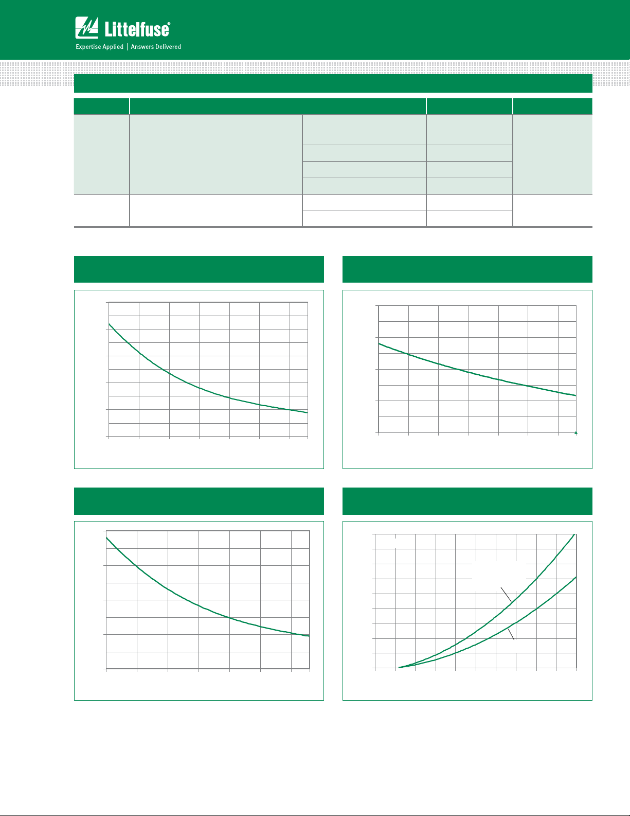
Figure 1: Normalized DC Gate Trigger Current
vs. Junction Temperature
2.5
2.0
C)
°
= 25
1.5
J
(T
GT
/I
GT
1.0
Ratio of I
0.5
0.0
-40 -15 10 35 60 85 110
Junction Tempera ture (TJ) -- (°C)
Figure 3: Normalized DC Holding Current
vs. Junction Temperature
2.0
1.5
C)
º
= 25
J
(T
H
/ I
1.0
H
Ratio of I
0.5
0.0
-40 -15 10 35 60 85 110
Junction Tempera ture (TJ) -- (ºC)
125
125
Figure 2: Normalized DC Gate Trigger Voltage
vs. Junction Temperature
2.0
1.5
= 25ºC)
J
(T
GT
/ V
GT
1.0
Ratio of V
0.5
0.0
-40 -15 10 35 60 85 110 125
Junction Tempera ture (TJ) -- (ºC)
Figure 4: On-State Current vs. On-State
Voltage (Typical)
90
TJ = 25°C
80
) – Amps
70
T
60
50
40
30
20
10
Instantaneo us On-state Current (i
0
0.7 0.8 0.9 1.0 1.1 1.2 1.3 1.4 1.5 1. 6 1.7
Instantaneous On-state Voltage (vT) – Vol ts
Qxx25P5/Qxx25R6
Qxx25L6/Qxx25NH6
Qxx25K6/Qxx25J6
Qxx25RH5/Qxx25LH5
Qxx25NH5
Qxx25R5
Qxx25N5
Qxx25xx & Qxx25xHx Series
134
Specifications are subject to change without notice.
©2013 Littelfuse, Inc
Revised: 09/23/13
Page 5

Teccor® brand Thyristors
25 Amp Standard & Alternistor (High Commutation) Triacs
Figure 5: Power Dissipation (Typical) vs. RMS
On-State Current
35
CURRENT WAVEFORM: Sinusoidal
LOAD: Resistive or Inductive
30
CONDUCTION ANGLE: 360°
25
20
] -- Watts
15
D(AV)
[P
10
5
Average On -State Po wer Dissipation
0
0 5 10 15 20 25
RMS On -Sta te Current [I
Qxx25R5
Qxx25N5
Qxx25P5/Qxx25R6
Qxx25L6/Qxx25NH6
Qxx25K6/Qxx25J6
Qxx25RH5/Qxx25LH5
Qxx25NH5
] -- Amps
T(RMS )
Figure 6: Maximum Allowable Case Temperature
vs. RMS On-State Current
130
120
110
100
90
) - °C
C
(T
80
70
CURRENT WAVEFORM: Sinusoidal
60
LOAD: Resistive or Inductive
Maxim um All owable Case Tem perature
CONDUCTION ANGLE: 360°
50
0 5 10 15 20 25 30
Qxx25L6
Qxx25LH5
RMS On -Sta te Current [I
Qxx25P5
Qxx25R6
Qxx25NH6
Qxx25RH5
Qxx25NH5
T(RMS )
Qxx25R5
Qxx25N5
Qxx25K6
Qxx25J6
] - Amps
Figure 7: Maximum Allowable Ambient Temperature vs. RMS On-State Current (TO-220 packages only)
120
CURRENT WAVEFORM: Sinusoidal
100
80
LOAD: Resistive or Inductive
CONDUCTION ANGLE: 360°
FREE AIR RATING
60
) --°C
A
(T
40
20
Maxim um All owable Ambient Tem perature
0
0.0 0.5 1.0 1.5 2.0 2. 5
RMS On -Sta te Current [I
T(RMS )
] -- Amps
Figure 8: Surge Peak On-State Current vs. Number of Cycles
1000
Qxx25P5/Qxx25R6
Qxx25L6/Qxx25NH6
Qxx25K6/Qxx25J6
Qxx25RH5/Qxx25LH5
Qxx25R5
Qxx25N5
Qxx25NH5
) – Amps
TSM
100
Peak Surge (Non-repetitive)
On-state Current (I
SUPPLY FREQUENCY: 60 Hz Sinusoidal
LOAD: Resistive
RMS On-State Current: [I
Specified Case Temperature
]: Maximum Rated Value at
T(RMS)
Notes:
1. Gate control may be lost during and immediately
following surge current interval.
2. Overload may not be repeated until junction
temperature has returned to steady-state
rated value.
10
1 10 100 1000
Qxx25xx & Qxx25xHx Series
Surge Current Duration -- Full Cycles
135
Specifications are subject to change without notice.
©2013 Littelfuse, Inc
Revised: 09/23/13
Page 6

Soldering Parameters
R
do
Teccor® brand Thyristors
25 Amp Standard & Alternistor (High Commutation) Triacs
Reflow Condition 1Co'SFFBTTFNCMZ
T
P
- Temperature Min (T
Pre Heat
- Temperature Max (T
- Time (min to max) (ts) oTFDT
Average ramp up rate (Liquidus Temp)
(TL) to peak
T
to TL - Ramp-up Rate 5°C/second max
S(max)
Reflow
- Temperature (TL) (Liquidus) 217°C
- Temperature (tL) oTFDPOET
Peak Temperature (TP) 260
Time within 5°C of actual peak
Temperature (tp)
) 150°C
s(min)
) 200°C
s(max)
5°C/second max
+0/-5
°C
oTFDPOET
T
L
T
S(max)
Temperature
T
S(min)
25
Ramp-up
Ramp-up
PreheatPreheat
t
S
time to peak temperature
Ramp-down Rate 5°C/second max
Time 25°C to peak Temperature (TP) 8 minutes Max.
Do not exceed 280°C
Physical Specifications Environmental Specifications
Terminal Finish 100% Matte Tin-plated
Body Material
UL recognized epoxy meeting flammability
classification 94V-0
Lead Material Copper Alloy
Design Considerations
Careful selection of the correct device for the application’s
operating parameters and environment will go a long way
toward extending the operating life of the Thyristor. Good
design practice should limit the maximum continuous
current through the main terminals to 75% of the device
rating. Other ways to ensure long life for a power discrete
semiconductor are proper heat sinking and selection of
voltage ratings for worst case conditions. Overheating,
overvoltage (including dv/dt), and surge currents are
the main killers of semiconductors. Correct mounting,
Test
High Temperature
Voltage Blocking
Temperature Cycling
Biased Temp &
Humidity
High Temp. Storage
Low-Temp Storage -40°C, 1008 hours
Thermal Shock
Autoclave
(Pressure Cooker Test)
Resistance to
Solder Heat
Solderability ANSI/J-STD-002, Category 3, Test A
Lead Bend MIL-STD-750: Method 2036, Condition E
Specifications and Conditions
MIL-STD-750: Method 1040, Condition A
Rated V
RRM
MIL-STD-750: Method 1051
-40°C to 125°C, 15-minute dwell,
100 cycles
EIA/JEDEC: JESD22-A101
320VDC, 85°C, 85%RH, 1008 hours
MIL-STD-750: Method 1031
150°C, 1008 hours
MIL-STD-750: Method 1056
0°C to 100°C, 5-minute dwell,
10-second transfer, 10 cycles
EIA/JEDEC: JESD22-A102
121°C, 100%RH, 2atm, 168 hours
MIL-STD-750: Method 2031
260°C, 10 seconds
soldering, and forming of the leads also help protect
against component damage.
t
P
t
L
Ramp-down
amp-
Time
, 125°C, 1008 hours
Qxx25xx & Qxx25xHx Series
136
Specifications are subject to change without notice.
©2013 Littelfuse, Inc
Revised: 09/23/13
Page 7

Teccor® brand Thyristors
25 Amp Standard & Alternistor (High Commutation) Triacs
Dimensions — TO-220AB (R Package) — Non-isolated Mounting Tab
7.01
.276
13.36
.526
2
Dimension
T
MEASURING POINT
C
E
Ø
C
D
G
A
MT2
B
F
R
L
H
K
J
MT1
MT2
GATE
O
P
NOTCH IN
GATE LEAD
TO ID.
NON-ISOLATED
TAB
N
M
AREA (REF.) 0.17 IN
8.13
.320
Note: Maximum torque to
be applied to mounting tab
is 8 in-lbs. (0.904 Nm).
Inches Millimeters
Min Max Min Max
A 0.380 0.420 9.65 10.67
B 0.105 0.115 2.67 2.92
C 0.230 0.250 5.84 6.35
D 0.590 0.620 14.99 15.75
E 0.142 0.147 3.61 3.73
F 0.110 0.130 2.79 3.30
G 0.540 0.575 13.72 14.61
H 0.025 0.035 0.64 0.89
J 0.195 0.205 4.95 5.21
K 0.095 0.105 2.41 2.67
L 0.060 0.075 1.52 1.91
M 0.085 0.095 2.16 2.41
N 0.018 0.024 0.46 0.61
O 0.178 0.188 4.52 4.78
P 0.045 0.060 1.14 1.52
R 0.038 0.048 0.97 1.22
Dimensions — TO-220AB (L Package) — Isolated Mounting Tab
7.01
.276
13.36
.526
2
T
MEASURING POINT AREA (REF.) 0.17 IN
C
E
Ø
C
D
G
A
B
F
R
L
H
K
J
MT1
MT2
GATE
O
P
N
M
8.13
.320
Note: Maximum torque to
be applied to mounting tab
is 8 in-lbs. (0.904 Nm).
Dimension
Inches Millimeters
Min Max Min Max
A 0.380 0.420 9.65 10.67
B 0.105 0.115 2.66 2.92
C 0.230 0.250 5.85 6.35
D 0.590 0.620 14.98 15.75
E 0.142 0.147 3.61 3.73
F 0.110 0.130 2.80 3.30
G 0.540 0.575 13.71 14.60
H 0.025 0.035 0.63 0.89
J 0.195 0.205 4.95 5.21
K 0.095 0.105 2.41 2.67
L 0.060 0.075 1.52 1.91
M 0.085 0.095 1.78 2.16
N 0.018 0.024 0.45 0.61
O 0.178 0.188 4.52 4.78
P 0.045 0.060 1.14 1.53
R 0.038 0.048 0.97 1.22
Qxx25xx & Qxx25xHx Series
137
Specifications are subject to change without notice.
©2013 Littelfuse, Inc
Revised: 09/23/13
Page 8

Teccor® brand Thyristors
25 Amp Standard & Alternistor (High Commutation) Triacs
Dimensions — TO-263 (N Package) — D2Pak Surface Mount
T
MEASURING POINT
16.89
C
C
GATE
V
A
S
K
D
F
2.16
.085
7. 0 1
.276
1.40
.055
2.03
.080
E
U
J
H
B
MT2
W
MT1
G
11.68
.460
7. 0 1
.276
.665
3.81
.150
8.89
.350
6.60
.260
AREA: 0.11
2
IN
8.41
7. 0 1
.331
.276
8.13
.320
Dimension
Inches Millimeters
Min Max Min Max
A 0.360 0.370 9.14 9.40
B 0.380 0.420 9.65 10.67
C 0.178 0.188 4.52 4.78
D 0.025 0.035 0.64 0.89
E 0.045 0.060 1.14 1.52
F 0.060 0.075 1.52 1.91
G 0.095 0.105 2.41 2.67
H 0.092 0.102 2.34 2.59
J 0.018 0.024 0.46 0.61
K 0.090 0.110 2.29 2.79
S 0.590 0.625 14.99 15.88
V 0.035 0.045 0.89 1.14
U 0.002 0.010 0.05 0.25
W 0.040 0.070 1.02 1.78
Dimensions — TO-218AC (K Package) — Isolated Mounting Tab
Measurement Point
T
C
A
P
MT1
MT2
B
F
R
K
L
E
U (diameter)
W
Gate
J
M
Q
N
Note: Maximum torque to
be applied to mounting tab
is 8 in-lbs. (0.904 Nm).
C
D
H
G
Dimension
Inches Millimeters
Min Max Min Max
A 0.810 0.835 20.57 21.21
B 0.610 0.630 15.49 16.00
C 0.178 0.188 4.52 4.78
D 0.055 0.070 1.40 1.78
E 0.487 0.497 12.37 12.62
F 0.635 0.655 16.13 16.64
G 0.022 0.029 0.56 0.74
H 0.075 0.095 1.91 2.41
J 0.575 0.625 14.61 15.88
K 0.211 0.219 5.36 5.56
L 0.422 0.437 10.72 11.10
M 0.058 0.068 1.47 1.73
N 0.045 0.055 1.14 1.40
P 0.095 0.115 2.41 2.92
Q 0.008 0.016 0.20 0.41
R 0.008 0.016 0.20 0.41
U 0.164 0.165 4.10 4.20
W 0.085 0.095 2.17 2.42
Qxx25xx & Qxx25xHx Series
138
Specifications are subject to change without notice.
©2013 Littelfuse, Inc
Revised: 09/23/13
Page 9

Teccor® brand Thyristors
25 Amp Standard & Alternistor (High Commutation) Triacs
Dimensions — TO-218X (J Package) — Isolated Mounting Tab
Measurement
Point
C
B
T
c
A
E
U
(diameter)
F
Z
D
Dimension
A 0.810 0.835 20.57 21.21
B 0.610 0.630 15.49 16.00
C 0.178 0.188 4.52 4.78
D 0.055 0.070 1.40 1.78
E 0.487 0.497 12.37 12.62
Inches Millimeters
Min Max Min Max
F 0.635 0.655 16.13 16.64
MT1
W
N
T
M
Y
K
V
X
Gate
R
S
P
MT2
L
Note: Maximum torque to
be applied to mounting tab
is 8 in-lbs. (0.904 Nm).
J
G
H
G 0.022 0.029 0.56 0.74
H 0.075 0.095 1.91 2.41
J 0.575 0.625 14.61 15.88
K 0.256 0.264 6.50 6.71
L 0.220 0.228 5.58 5.79
M 0.080 0.088 2.03 2.24
N 0.169 0.177 4.29 4.49
P 0.034 0.042 0.86 1.07
R 0.113 0.121 2.87 3.07
S 0.086 0.096 2.18 2.44
T 0.156 0.166 3.96 4.22
U 0.164 0.165 0.410 0.420
V 0.603 0.618 15.31 15.70
W 0.000 0.005 0.00 0.13
X 0.003 0.012 0.07 0.30
Y 0.028 0.032 0.71 0.81
Z 0.085 0.095 2.17 2.42
Dimensions — TO-3 (P Package) Fastpak — Isolated Mounting Tab
A
B
D
MT2
F
MT1
Gate
TC MeasuringPoint
Φ J (MT1, MT2)
M
5 - Φ N
Thickness off all three copper-alloy terminals is .032" (0.81 mm).
E
C
I
T
U
W
L
V
R
Φ K (Gate)
S
H
Φ G
Q
O
P
Dimension
T (MT1) 0.321 0.329 8.15 8.35
T (MT2) 0.321 0.329 8.15 8.35
T (Gate) 0.220 0.228 5.60 5.80
U (MT1) 0.246 0.254 6.25 6.45
U (MT2) 0.246 0.254 6.25 6.45
U (Gate) 0.183 0.191 4.65 4.85
Maximum torque to be applied to mounting tab is 8 in-lbs (0.904Nm).
Inches Millimeters
Min Max Min Max
A 1.531 1.543 38.90 39.20
B 1.177 1.185 29.90 30.10
C 0.843 0.850 21.40 21.60
D 0.780 0.795 19.80 20.20
E 0.783 0.791 19.90 20.10
F 0.874 0.906 22.20 23.00
G 0.161 0.169 4.10 4.30
H 0.386 0.465 9.80 11.80
I 0.508 0.587 12.90 14.90
J 0.079 0.087 2.00 2.20
K 0.047 0.055 1.20 1.40
L 0.307 0.319 7.80 8.10
M 0.372 0.396 9.45 10.05
N 0.043 0.059 1.10 1.50
O 0.315 0.331 8.00 8.40
P 0.098 0.106 2.50 2.70
Q 0.846 0.886 21.50 22.50
R 0.244 0.256 6.20 6.50
S 0.106 0.130 2.70 3.30
V 0.120 0.130 3.05 3.30
W 0.175 0.185 4.45 4.70
Qxx25xx & Qxx25xHx Series
139
Specifications are subject to change without notice.
©2013 Littelfuse, Inc
Revised: 09/23/13
Page 10

Product Selector
Teccor® brand Thyristors
25 Amp Standard & Alternistor (High Commutation) Triacs
Part Number
400V 600V 800V 1000V I - II - III IV
Voltage Gate Sensitivity Quadrants
Package
Qxx25R5 XXXX 50 mA120 mA (TYP) TO-220R
Qxx25N5 XXXX 50 mA120 mA (TYP) TO-263 D
2
-Pak
Qxx25P5 X X 50 mA 120 mA (TYP) Fastpak
Qxx25RH5 X X X 50 mA TO-220R
Qxx25LH5 X X X 50 mA TO-220L
Qxx25NH5 X X X 50 mA TO-263 D2-Pak
Qxx25R6 XXXX 80 mA TO-220R
Qxx25L6 XXXX 80 mA TO-220L
Qxx25NH6 XXXX 80 mA TO-263 D2-Pak
Qxx25J6 X X X 80 mA TO-218X
Qxx25K6 XXXX 80 mA TO-218AC
Packing Options
Part Number Marking Weight Packing Mode Base Quantity
Qxx25R5 Qxx25R5 2.20g Bulk 500
Qxx25R5TP Qxx25R5 2.20g Tube 500 (50 per tube)
Qxx25N5TP Qxx25N5 1.60g Tube 500 (50 per tube)
Qxx25N5RP Qxx25N5 1.60g Embossed Carrier 500
Qxx25RH5 Qxx25RH5 2.20g Bulk 500
Qxx25RH5TP Qxx25RH5 2.20g Tube 500 (50 per tube)
Qxx25LH5 Qxx25LH5 2.20g Bulk 500
Qxx25LH5TP Qxx25LH5 2.20g Tube 500 (50 per tube)
Qxx25NH5TP Qxx25NH5 1.60g Tube 500 (50 per tube)
Qxx25NH5RP Qxx25NH5 1.60g Embossed Carrier 500
Qxx25P5 Qxx25P5 21.4g Bulk 200
Qxx25R6 Qxx25R6 2.20g Bulk 500
Qxx25R6TP Qxx25R6 2.20g Tube 500 (50 per tube)
Qxx25L6 Qxx25L6 2.20g Bulk 500
Qxx25L6TP Qxx25L6 2.20g Tube 500 (50 per tube)
Qxx25NH6TP Qxx25NH6 1.60g Tube 500 (50 per tube)
Qxx25NH6RP Qxx25NH6 1.60g Embossed Carrier 500
Qxx25J6TP Qxx25J6 5.23g Tube 250 (25 per tube)
Qxx25K6TP Qxx25K6 4.40g Tube 250 (25 per tube)
Qxx25xx & Qxx25xHx Series
140
Specifications are subject to change without notice.
©2013 Littelfuse, Inc
Revised: 09/23/13
Page 11

Teccor® brand Thyristors
25 Amp Standard & Alternistor (High Commutation) Triacs
TO-263 Embossed Carrier Reel Pack (RP) Specifications
Meets all EIA-481-2 Standards
0.63
(16.0)
0.157
(4.0)
0.059
(1.5)
Gate
DIA
MT1 / Cathode
0.945
(24.0)
0.827
(21.0)
*
*Cover tape
MT2 / Anode
12.99
0.512 (13.0) Arbor
Hole Dia.
1.01
(25.7)
(330.0)
Dimensions
are in inches
(and millimeters).
Direction of Feed
Part Numbering System Part Marking System
DEVICE TYPE
Q: Triac or Alternistor
VOLTAGE RATING
40: 400V
60: 600V
80: 800V
K0: 1000V
CURRENT RATING
25: 25A
Q 60 25 N H6
SENSITIVITY
Standard Triac
5: 50mA
Alternistor
H5: 50mA
6: 80mA
H6: 80mA
PACKAGE TYPE
L : TO-220AB Isolated
R : TO-220AB Non-Isolated
N : TO-263 (D
K : TO-218AC Isolated
J : TO-218X Isolated
P : Fastpak
2
-Pak)
TO-220 AB - (L and R Package)
TO-263 AB - (N Package)
Q6025R5
M
Y
®
Date Code Marking
Y:Year Code
M: Month Code
XXX: Lot Trace Code
Fastpak - (P Package)
TO-218AC - (K Package)
TO-218X - (J Package)
Q6025K6
YMLXX
®
Date Code Marking
Y:Year Code
M: Month Code
L: Location Code
XX: Lot Serial Code
Qxx25xx & Qxx25xHx Series
141
Q6025P5
YMXXX
®
Specifications are subject to change without notice.
©2013 Littelfuse, Inc
Revised: 09/23/13
 Loading...