

Littelfuse Kxxx1GL User Manual
Teccor® brand Thyristors
Multipulse™ SIDACs
Kxxx1GL Series
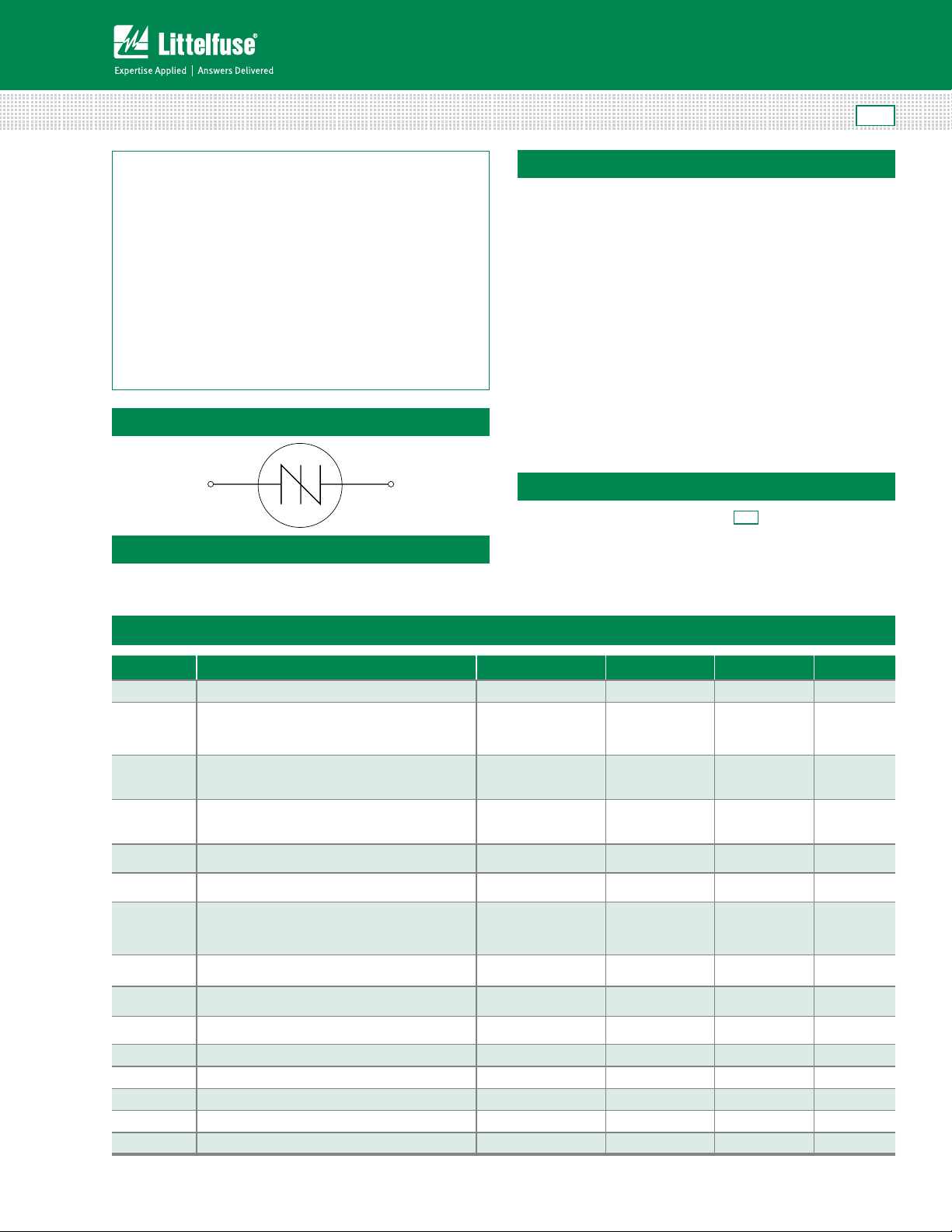
Schematic Symbol
Applications
Typical application circuit presented in Figure 10 of this data
sheet (Typical Metal Halide Ignitor Circuit).
RoHS
Description
The Multipulse™ SIDAC is a voltage switch used in MetalHalide lamp ignition circuits, as well as High Pressure
Sodium lamp ignition circuits for outdoor street and area
lighting. This robust solid-state switch is designed to handle
lamp igniter applications requiring operation at ambient
temperatures up to 90°C where igniter circuit components
can raise SIDAC junction temperature up to 125°C, especially
when the lamp element is removed or ruptured. Its excellent
commutation time (t
suited for producing multiple pulses in each half cycle of
50/60 Hz line voltage. The Multipulse
) makes this robust product best
COMM
™
SIDAC is offered in a
DO-15 axial leaded package.
Kxxx1GL SIDAC has a repetitive off-state blocking voltage
(V
) of 180V to 200V minimum depending actual device
DRM
type. Blocking capability is ensured by glass passivated
junctions for best reliability. The package is epoxy
encapsulated with tin plated copper alloy leads.
Features
• AC circuit oriented
RoHS
• Compliant
• Triggering Voltage of 200
to 265V
Electrical Specifications
Symbol Parameters Test Conditions Min Max Unit
V
T
I
TRM
V
BO
V
DRM
I
T(RMS)
I
H
R
S
t
COMM
I
BO
I
TSM
Peak Non-Repetitive Surge Current
On-State RMS Current, TJ < 125ºC
Dynamic Holding Current, R=100 Ω
Switching Resistance, RS=
(IS – IBO)
Non-repetitive 1 cycle On-State peak value
di/dt Critical Rate of Rise of On-State Current 150 A/μsec
dv/dt Critical Rate of Rise of Off-State Voltage 150 0 V/μsec
T
S
T
J
R
θJL
Kxxx1GL Series
Max Operating Junction Temperature -40 +125 °C
On-state Voltage IT=1A 3 V
TA=25 °C
Pulse Wave = 10μs,
50 A
Sine Wave, f=120Hz
Breakover/Trigger Voltage
Repetitive Peak Off-State Voltage
(VBO – VS)
________
Commutation Time TJ < 125ºC
Breakover Current
K2201GL
K2401GL
K2501GL
K2201GL
K2401GL
K2501GL
50/60Hz
Sine Wave
50/60Hz
Sine Wave
50/60Hz
Sine Wave
See test circuit and
waveform in Figure 9
50/60Hz
Sine Wave
60Hz
50Hz
200
220
240
230
250
265
180
190
200
1 A
30 TYP mA
100 Ω
100 μsec
10 uA
20.0
16.7
Storage Temperature Range -40 +125 °C
Thermal Resistance Junction to lead 18 °C/W
1
Specifications are subject to change without notice.
©2013 Littelfuse, Inc
Revised: 12/26/13
V
V
A
Teccor® brand Thyristors
81
Multipulse™ SIDACs
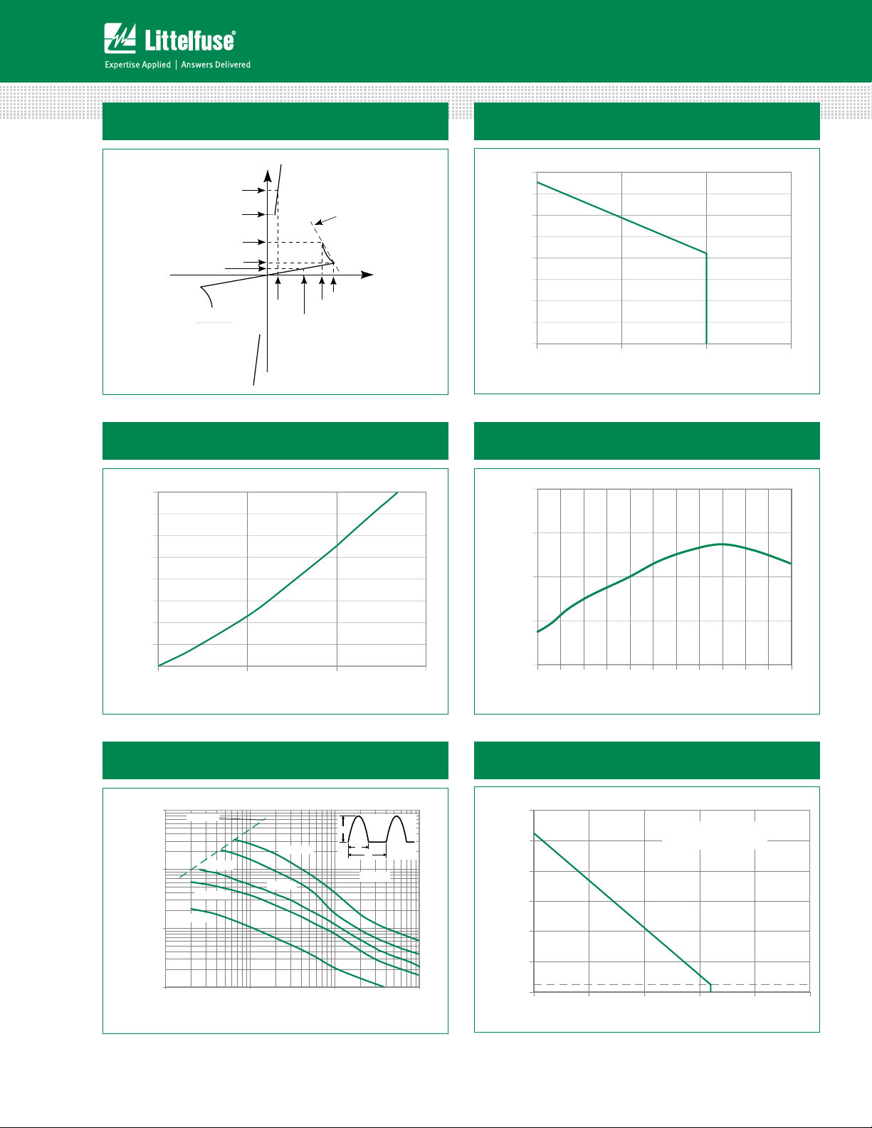
Figure 1: Characteristics
+I
I
T
I
H
I
S
I
BO
I
R
=
S
DRM
(VBO - VS)
- IBO)
(I
S
V
V
T
V
DRM
-V
-I
Figure 3: Power Dissipation (Typical)
vs. On-State Current
4.0
3.5
3.0
2.5
(Watts)
D
2.0
1.5
Average P
1.0
0.5
0.0
RMS On-State Current (Amps)
Figure 2: Maximum Allowable Lead/Tab Temperature
vs. On-State Current
130
120
R
S
+V
V
BO
S
110
100
90
80
Te mperature (°C)
70
Maximum Allowable Lead
60
50
2.01.51.00
RMS On-State Current (Amps)
Figure 4: VBO Change
vs. Junction Temperature
10.0
BO
5.0
0.0
Change (%)
-5.0
Normalized Percentage of V
-10.0
1.51.00.50.0
-40-25 -10520 35 50 65 80 95 11 0125
Junction Te mperature (°C)
Figure 5: Pulse On-State
Current Rating
1000
di/dt limit
100
)-Amps
TRM
10
Current (I
Repetitive Peak On-State
1
110 100 1000
Kxxx1GL Series
120 Hz
1KHz
5KHz
f = 5Hz
60 Hz
Pulse Base Width (tO)-µs
Figure 6: Maximum Allowable Ambient Temperature
vs. On-State Current
140
I
TM
t
O
1/f
TJ=125˚C
120
100
80
) - °C
A
(T
60
40
25
Maximum Allowable Ambient Te mperature
20
0.00.2 0.40.6 0.
RMS On-State Current [I
2
CURRENT WAVEFORM: Sinusoidal - 60Hz
LOAD: Resistive or Inductive
FREE AIR RATING
] - Amps
T(RMS)
Specifications are subject to change without notice.
©2013 Littelfuse, Inc
.0
Revised: 12/26/13
 Loading...