

Page 1
Global LCD Panel Exchange Center
www.panelook.com
LITEMAX DLF/DLH1954
Sunlight Readable 19” LED B/L LCD
(1st Edition 6/6/2008 )
All information is subject to change without notice.
Approved by Checked by Prepared by
David Sharline Eric
LITEMAX Electronics Inc.
8F, No.137, Lane 235, Bau-chiau Rd.,
Shin-dian City, Taipei County, Taiwan R.O.C.
Tel : 886-2-8919-1858
Fax: 886-2-8919-1300
Homepage:
http://www.litemax.com.tw
Page 1
One step solution for LCD / PDP / OLED panel application: Datasheet, inventory and accessory!
www.panelook.com
Page 2
Global LCD Panel Exchange Center
Record Revision
Version and Date Page Old Description New Description Remark
www.panelook.com
Page 2
One step solution for LCD / PDP / OLED panel application: Datasheet, inventory and accessory!
www.panelook.com
Page 3

Global LCD Panel Exchange Center
Contents
Record Revision 2
Contents 3
Handling Precautions 4
General Description 5
Display Characteristics 5
Optical Characteristics 6
Optical Test 6
Test Mode: 7
Functional Block Diagram 9
Absolute Maximum Ratings 10
Absolute Ratings of TFT LCD Module 10
Absolute Ratings of Backlight Unit 10
Absolute Ratings of Environment 10
Electrical Characteristics 11
TFT LCD Module 11
Pixel Format Image 12
The Input Data Format 13
Signal Description 14
Interface Timing 15
Power ON/OFF Sequence 17
Connector & Pin Assignment 18
TFT LCD Module 18
www.panelook.com
Page 3
One step solution for LCD / PDP / OLED panel application: Datasheet, inventory and accessory!
www.panelook.com
Page 4

Global LCD Panel Exchange Center
Handling Precautions
1) Since front polarizer is easily damaged, be extremely careful when handling panel.
2) Be sure to turn off power supply when inserting or disconnecting from input
connectors.
3) Wipe off water immediately. Long contact with water may cause discoloration or spots.
4) When the panel surface is soiled, wipe it with absorbent cotton or other soft cloth.
5) Since the panel is made of glass, it may break or crack if dropped or bumped on a
hard surface.
6) Since CMOS LSI is used in this module, be careful of static electricity by grounding
those handling the display.
7) Do not open nor modify the module assembly.
8) Do not press or touch the panel surface with hands or tools.
www.panelook.com
9) Do not press or move the reflector sheet at the back of the module in any direction.
10) **At the insertion or removal of the signal Interface Connector, be sure not to rotate
nor tilt the interface connector of the TFT module.
11) After installation of the TFT module into an enclosure (Desktop monitor Bezel, for
example), do not twist nor bend the TFT Module even momentarily. Design the
enclosure so that no bending/twisting forces are applied to the TFT module. Otherwise
the TFT module may be damaged.
Page 4
One step solution for LCD / PDP / OLED panel application: Datasheet, inventory and accessory!
www.panelook.com
Page 5
Global LCD Panel Exchange Center
General Description
AU1954 is a Color Active Matrix Liquid Crystal Display composed of a TFT-LCD panel, a
driver circuit, and a backlight system. The screen format is intended to support the SXGA
(1280(H) x 1024(V)) screen and 16.7M colors (RGB 6-bits + HiFRC data). All input signals
are LVDS interface compatible. Inverter card of backlight is not included. AU1954 is
designed for a display unit of outdoor display.
Display Characteristics
The following items are characteristics summary on the table under 25 ℃condition:
Items Unit Specifications
Screen Diagonal [mm] 482.6 (19.0" )
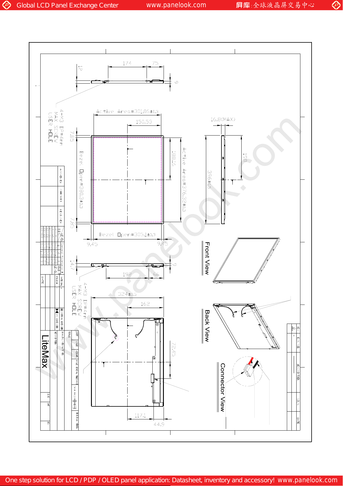
Active Area [mm] 376.32 (H) x 301.06 (V)
www.panelook.com
1280(x3) x 1024 Pixels H x V
Pixel Pitch [mm] 0.294 (per one triad) x 0.294
[cd/m
Optical ResponseTime [msec] 5 ms(Typ, on/off)
Nominal Input Voltage VDD [Volt] +5.0 V
Power Consumption
Weight [Grams] 2100
Physical Size (H x V x D) [mm] 396 (H) x 324 (V) x 16.3(D) (Typ)
[Watt]
Support Color
Temperature Range
Operating
Storage (Non-Operating) [
RoHS Compliance RoHS Compliance
oC] [oC]
R.G.B. Vertical Stripe Pixel Arrangement
Normally White Display Mode
2]
1000 (center, Typ) White Luminance
800 : 1 (Typ) Contrast Ratio
36.11W (Typ)
(PDD=5.11W, PBL=31 W )
Dual channel LVDS Electrical Interface
Hard-coating (3H), Non-Glare treatment Surface Treatment
16.7M colors (RGB 6-bit data + HiFRC
data)
0 to +50
-20 to +60
Page 5
One step solution for LCD / PDP / OLED panel application: Datasheet, inventory and accessory!
www.panelook.com
Page 6
Global LCD Panel Exchange Center
Optical Characteristics
The optical characteristics are measured under stable conditions at 25℃
(Room Temperature):
Optical Test
Test Conditions
Room
Temperature
Room Luminance 10nits
25℃
www.panelook.com
R. Humidity
50±10%
Surveying
Instruments
Panel
Model No M190EG02 Version V4
Brightness
TOPCON BM-7;KLEIN K-10
100% (R:100 %,G:100
Contrast
100%
%,B100 %)
Power
Consumption
Input Voltage 5V(Typ.) Input Current 1.02A(Typ.)
Backlight
CCFL or LED LED 96 PCS
Inverter LID19A01 Frequency None
Input Voltage 17.8V Input Current 1.73A
Power
Consumption
Test Data
Item Symbol Condition Data Unit Note
Color
chromaticity
Center Luminance of White Lc 1015
Average La 994
Uniform % Lu 78
Contrast Ratio CR 900 -
Color Saturation
Viewing Angle Deg
5.11W(Typ.)
31W Time 30 minute
Red
Green
Blue
White
Horizontal
Vertical
Rx 0.6337 Ry 0.3535 Gx 0.3292 Gy 0.5958 Bx 0.1437 By 0.0565 Wx 0.2906 Wy 0.3046 -
NTSC 75
θx+ 80
θx- 80
θy+ 80
θy-
θx=0
θy=0
BM-7
θx=0
θy=0
Klein
K-10
CR≧10
A/D Board
80
cd/
㎡
cd/
㎡
%
AD5621GA
Test Mode:
(1)(2)(3)
Test Mode:
(1)(4)
Test Mode:
(1)(3)
Page 6
One step solution for LCD / PDP / OLED panel application: Datasheet, inventory and accessory!
www.panelook.com
Page 7
Global LCD Panel Exchange Center
Reliability
Item fill the bill Note
Storage Temperature
Operating Temperature
High Temperature &Humidity
Thermal Shock
Life -----℃--------hours
Vibration
Shock(white carton)
Drop (white carton)
www.panelook.com
Max:60 ℃
Min:-20 ℃
Max:50 ℃ Time: 24 hours
Min:0 ℃ Time: 24 hours
50 ℃,RH 80 %,24 hours
0 ℃,0.5 hour to 50 ℃,0.5 hour
100 cycle,1 hour/cycle
1.5 G,10-200-10 Hz,30 Min
each Axis (X,Y,Z)
50 G,20 ms ,
Half-sine wave (X,Y,Z)
Height: 60 cm
1corner,3edges,6surfaces
(ASTMD4169-I)
Time: 24 hours
Time: 24 hours
Test Mode:(5)
Test Mode(6)
Test Mode:(7)
Test Mode:(7)
Test Mode:
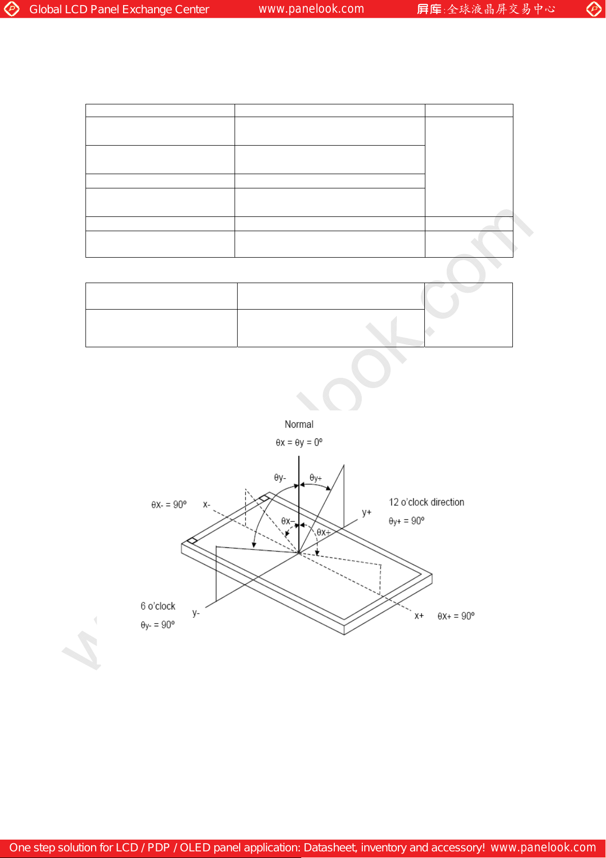
Note (1) Definition of Viewing Angle(θx,θy):
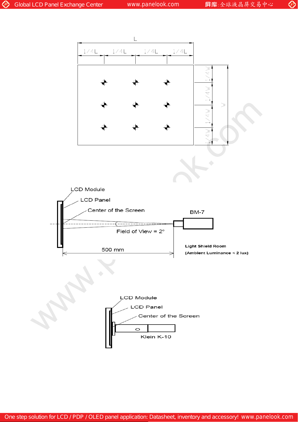
Note (2) Definition of Test Point:
Page 7
One step solution for LCD / PDP / OLED panel application: Datasheet, inventory and accessory!
www.panelook.com
Page 8
Global LCD Panel Exchange Center
1
2
3
www.panelook.com
BA C
Active Area
Note (3) BM-7 Measurement Setup:
Note (4) □Klein K-10 Measurement Setup:
Page 8
One step solution for LCD / PDP / OLED panel application: Datasheet, inventory and accessory!
www.panelook.com
Page 9
Global LCD Panel Exchange Center
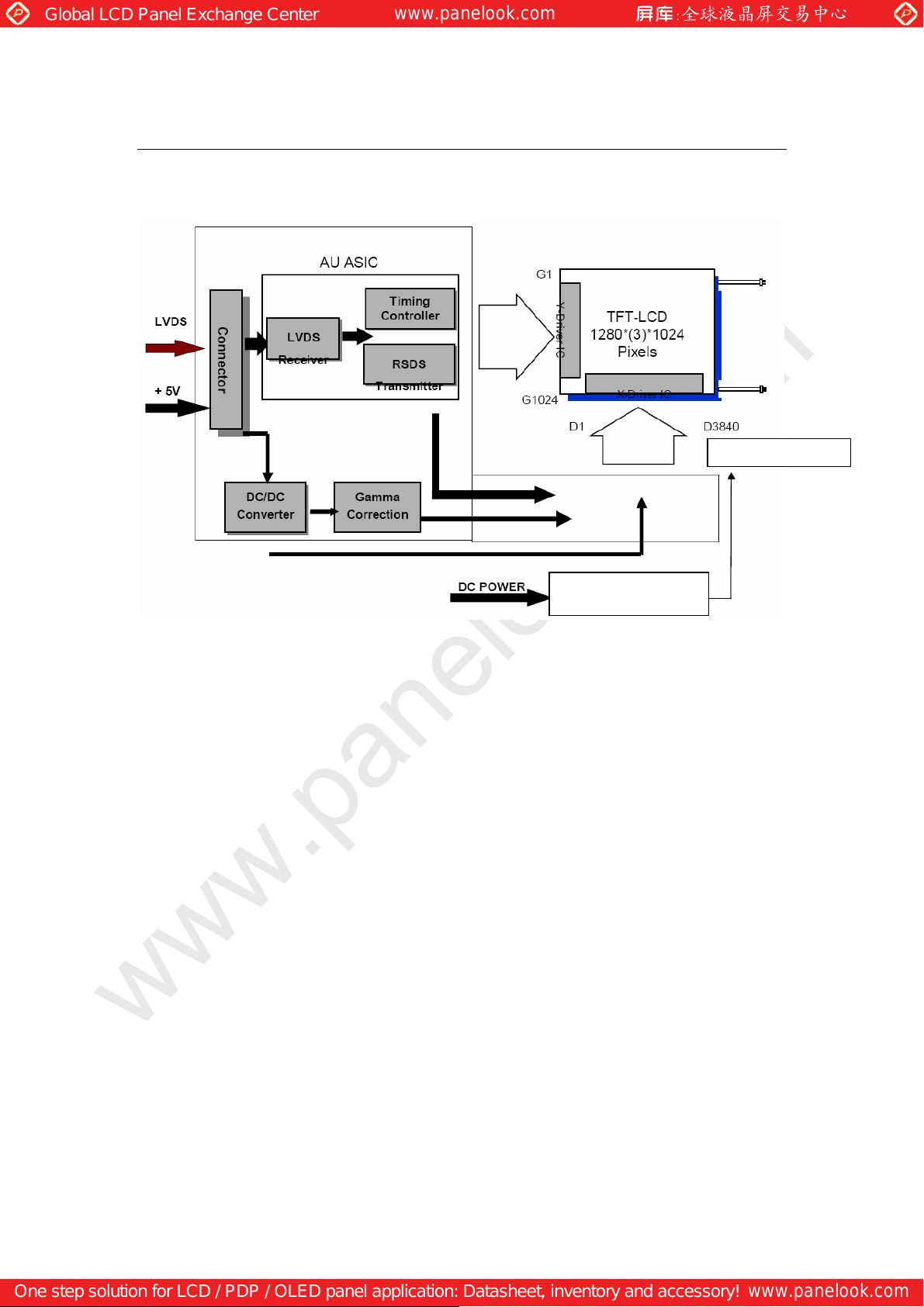
Functional Block Diagram
The following diagram shows the functional block of the 19.0 inches Color TFT-LCD
Module:
www.panelook.com
LED bar line
LED Driving Board
Page 9
One step solution for LCD / PDP / OLED panel application: Datasheet, inventory and accessory!
www.panelook.com
Page 10
Global LCD Panel Exchange Center
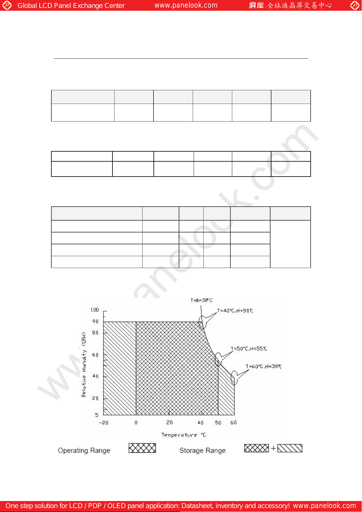
Absolute Maximum Ratings
Absolute maximum ratings of the module are as following:
Absolute Ratings of TFT LCD Module
Item Symbol Min. Max. Unit Conditions
www.panelook.com
Logic/LCD Drive
Voltage
VDD -0.3 +6 [Volt] Note 1, 2
Absolute Ratings of Backlight Unit
Item
LED Light bar
Current
Symbol Min Max Unit Conditions
I
LED
-
865 [mA] rms Note 1,2
Absolute Ratings of Environment
Item Symbol Min. Max. Unit Conditions
Operating Temperature TOP 0 +50 [oC]
Operation Humidity HOP 5 90 [%RH]
Storage Temperature TST -20 +60 [oC]
Storage Humidity HST
Note 1: With in Ta= 25℃
Note 2: Permanent damage to the device may occur if exceed maximum values
Note 3: For quality performance, please refer to AUO IIS (Incoming Inspection Standard).
5 90 [%RH]
Note 3
Page 10
One step solution for LCD / PDP / OLED panel application: Datasheet, inventory and accessory!
www.panelook.com
Page 11
Global LCD Panel Exchange Center
Electrical Characteristics
TFT LCD Module
Power Specification
Input power specifications are as follows:
Symble Parameter Min. Typ. Max. Unit Condition
www.panelook.com
VDD
IDD Input Current - 1.02 1.34 [A]
PDD VDD Power - 5.11 6.71 [Watt]
IRush Inrush Current - - 2.5 [A] Note 2
VDDrp
Logic/LCD Drive
Voltage
Allowable
Logic/LCD Drive
Ripple Voltage
4.5 5.0 5.5 [Volt]
[mV]
- - 100
p-p
±10%
VDD= 5.0V, All Black
Pattern At 75Hz, +30%
VDD= 5.0V, All Black
Pattern At 75Hz , Note 1
VDD= 5.0V, All Black
Pattern At 75Hz
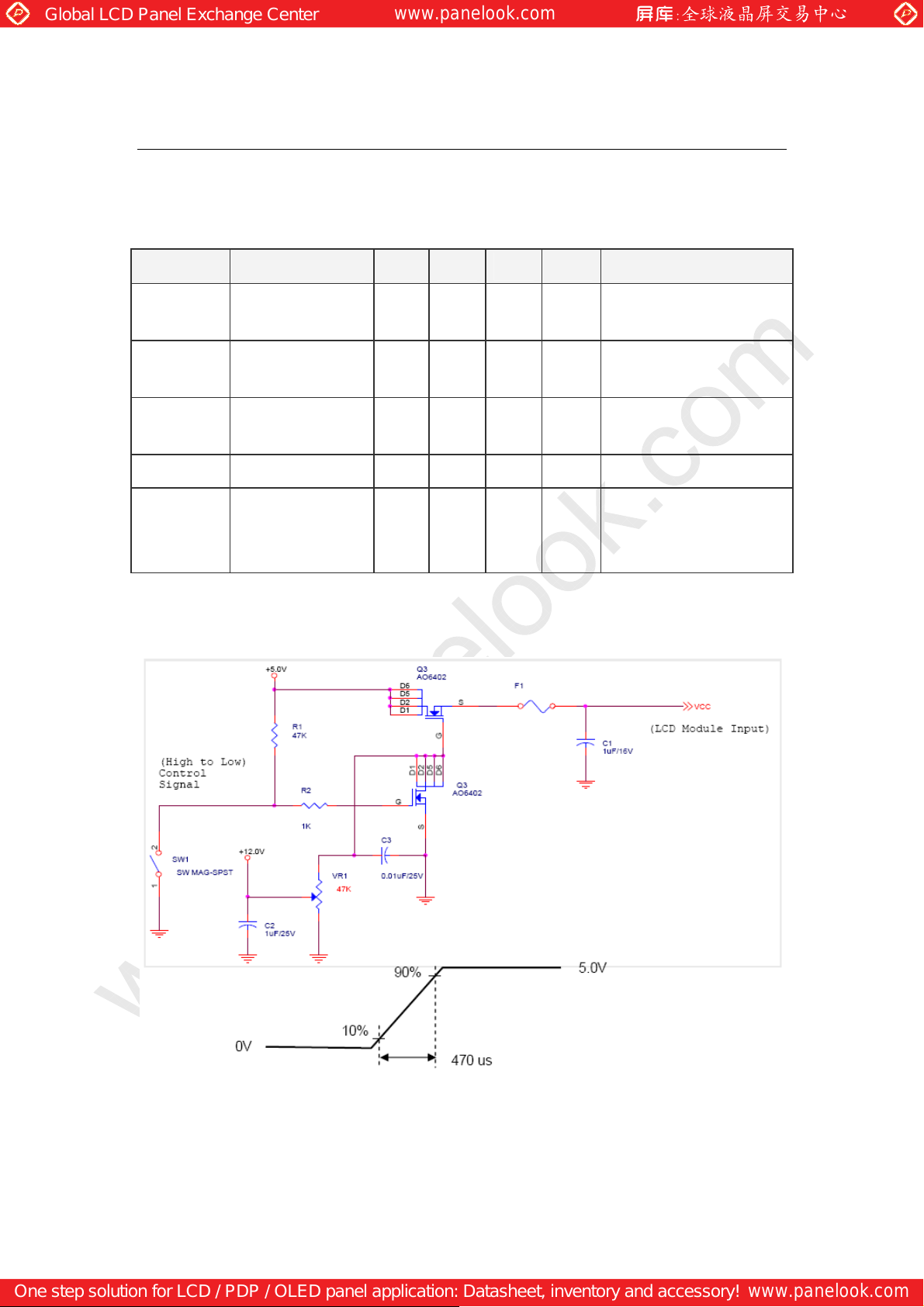
Note 1: The variance of VDD power consumption is ±30%.
Note 2: Measurement conditions:
Page 11
One step solution for LCD / PDP / OLED panel application: Datasheet, inventory and accessory!
www.panelook.com
Page 12
Global LCD Panel Exchange Center
Signal Characteristic
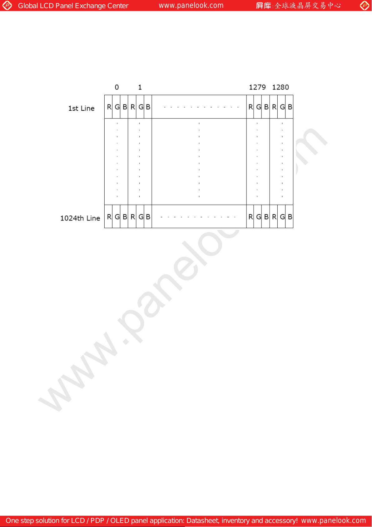
Pixel Format Image
Following figure shows the relationship of the input signals and LCD pixel format.
www.panelook.com
Page 12
One step solution for LCD / PDP / OLED panel application: Datasheet, inventory and accessory!
www.panelook.com
Page 13
Global LCD Panel Exchange Center
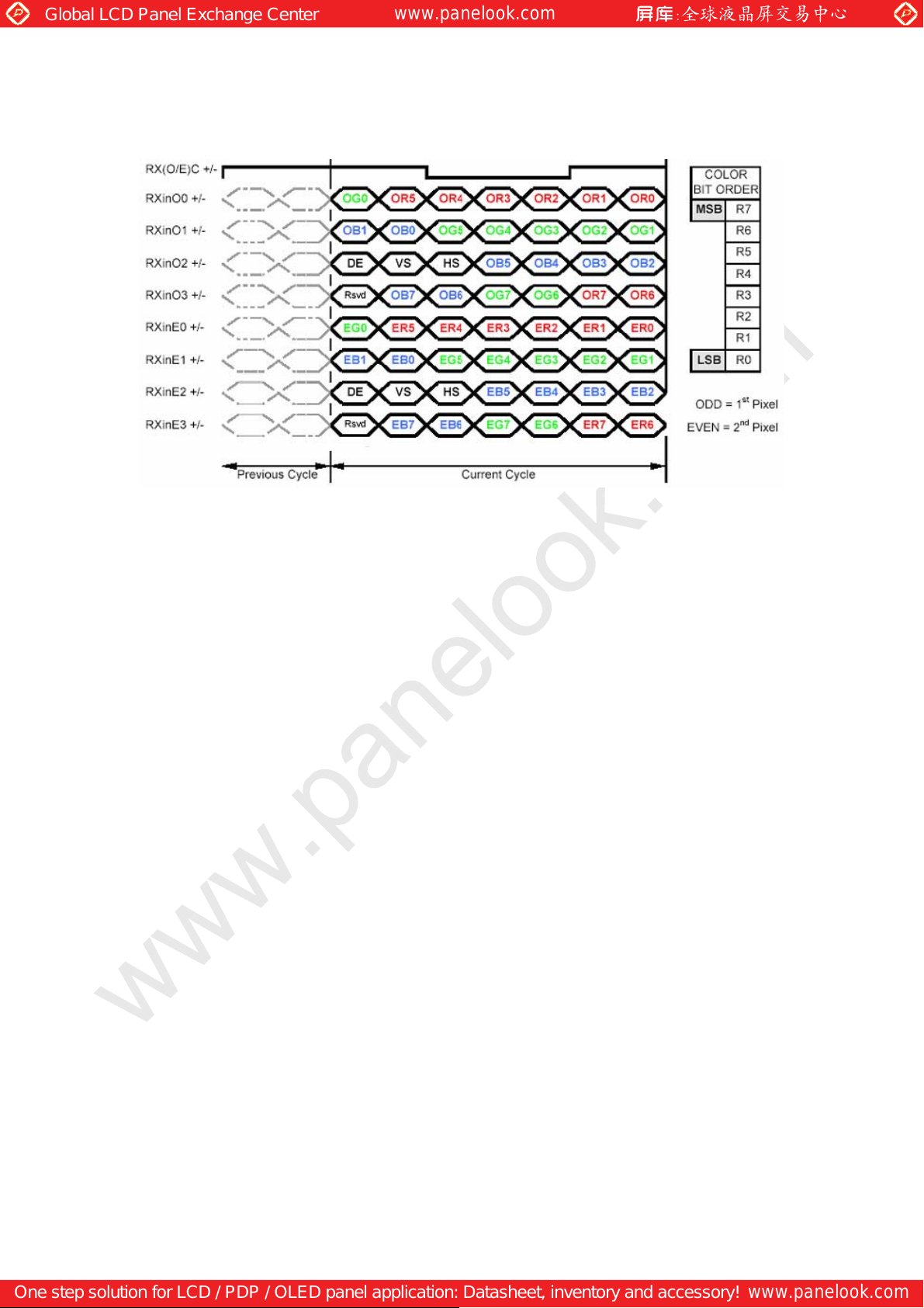
The Input Data Format
www.panelook.com
Note1: Normally, DE, VS, HS on EVEN channel is not used.
Note2: Please follow PSWG.
Note3: 8-bit in
Page 13
One step solution for LCD / PDP / OLED panel application: Datasheet, inventory and accessory!
www.panelook.com
Page 14
Global LCD Panel Exchange Center
Signal Description
The module using a pair of LVDS receiver SN75LVDS82(Texas Instruments) or
compatible. LVDS is a differential signal technology for LCD interface and high speed data
transfer device. Transmitter shall be SN75LVDS83(negative edge sampling) or compatible.
The first LVDS port(RxOxxx) transmits odd pixels while the second LVDS port(RxExxx)
transmits even pixels.
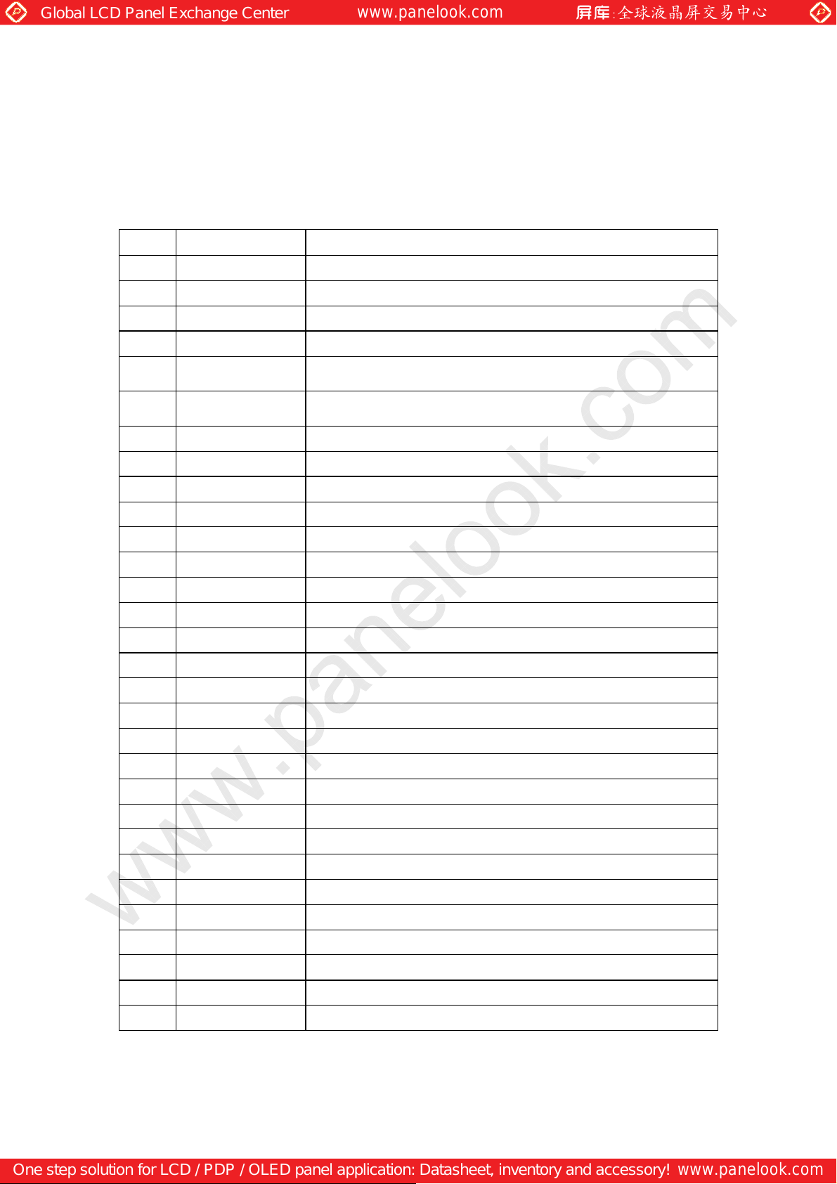
PIN # SIGNAL NAME DESCRIPTION
1 RxOIN0 Negative LVDS differential data input (Odd data)
2 RxOIN0+ Positive LVDS differential data input (Odd data)
3 RxOIN1 Negative LVDS differential data input (Odd data)
4 RxOIN1+ Positive LVDS differential data input (Odd data)
5 RxOIN2
6
7 VSS Power Ground
RxOIN2+
www.panelook.com
Negative LVDS differential data input (Odd data,
H-Sync,V-Sync,DSPTMG)
Positive LVDS differential data input (Odd data,
H-Sync,V-Sync,DSPTMG)
8 RxOCLKIN- Negative LVDS differential clock input (Odd clock)
9 RxOCLKIN+ Positive LVDS differential clock input (Odd clock)
10 RxOIN3 Negative LVDS differential data input (Odd data)
11 RxOIN3+ Positive LVDS differential data input (Odd data)
12 RxEIN0 Negative LVDS differential data input (Even data)
13 RxEIN0+ Positive LVDS differential data input (Even data)
14 VSS Power Ground
15 RxEIN1 Negative LVDS differential data input (Even data)
16 RxEIN1+ Positive LVDS differential data input (Even data)
17 VSS Power Ground
18 RxEIN2 Negative LVDS differential data input (Even data)
19 RxEIN2+ Positive LVDS differential data input (Even data)
20 RxECLKIN- Negative LVDS differential clock input (Even clock)
21 RxECLKIN+ Positive LVDS differential clock input (Even clock)
22 RxEIN3 Negative LVDS differential data input (Even data)
23 RxEIN3+ Positive LVDS differential data input (Even data)
24 VSS Power Ground
25 VSS Power Ground
26 NC No Connection ( for AUO test)
27 VSS Power Ground
28 VCC +5.0V Power Supply
29 VCC +5.0V Power Supply
30 VCC +5.0V Power Supply
Page 14
One step solution for LCD / PDP / OLED panel application: Datasheet, inventory and accessory!
www.panelook.com
Page 15
Global LCD Panel Exchange Center
Note1: Start from left side
www.panelook.com
Note2: Input signals of odd and even clock shall be the same timing. Note3: Please follow
PSWG.
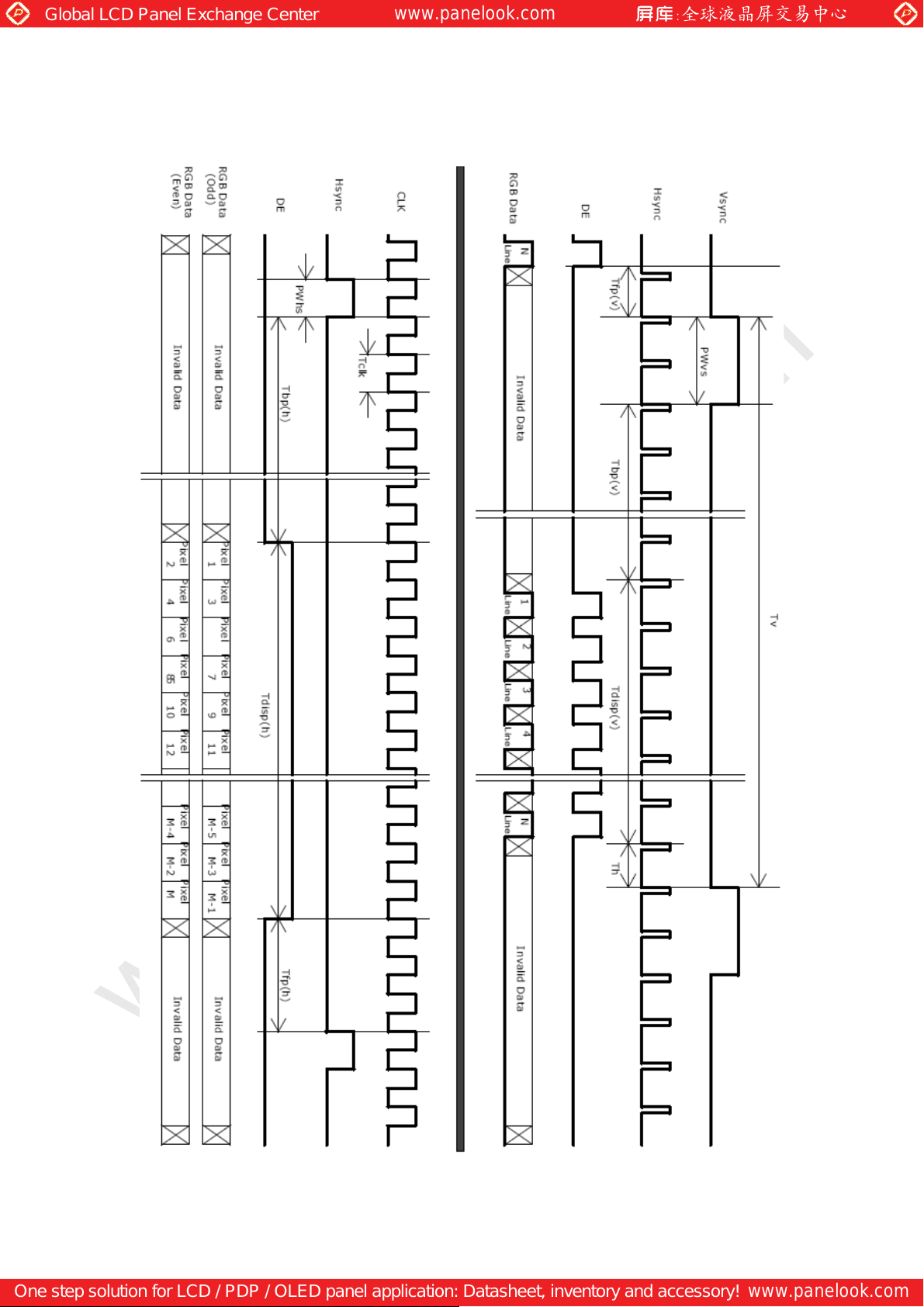
Interface Timing
Timing Characteristics
Item Symbol Min Typ Max Unit
Data CLK Tclk 40 54 67.5 MHz
H-section
V-section
Frame Rate F 50 60 75 Hz
Note : DE mode only
Period Th 680 844 1024 Tclk
Display Area Tdisp(h) 640 640 640 Tclk
Period Tv 1028 1066 2048 Th
Display Area Tdisp(v) 1024 1024 1024 Th
Page 15
One step solution for LCD / PDP / OLED panel application: Datasheet, inventory and accessory!
www.panelook.com
Page 16
Global LCD Panel Exchange Center
Timing Diagram
www.panelook.com
Page 16
One step solution for LCD / PDP / OLED panel application: Datasheet, inventory and accessory!
www.panelook.com
Page 17
Global LCD Panel Exchange Center
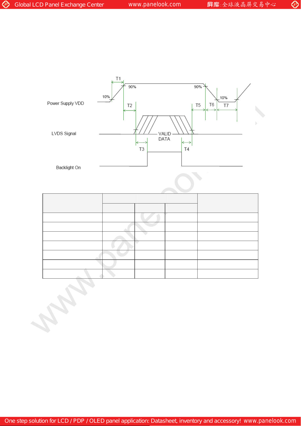
Power ON/OFF Sequence
VDD power and lamp on/off sequence is as follows. Interface signals are also shown in
the chart. Signals from any system shall be Hi-Z state or low level when VDD is off.
www.panelook.com
Power Sequence Timing
Value
Parameter
Min. Typ. Max.
T1 0.5 - 10 [ms]
T2 0 - 50 [ms]
T3 200 - - [ms]
T4 200 - - [ms]
T5 0 16 50 [ms]
T6 - - 10 [ms]
T7 500 - - [ms]
Note: The values of the table are follow PSWG.
Unit
Page 17
One step solution for LCD / PDP / OLED panel application: Datasheet, inventory and accessory!
www.panelook.com
Page 18
Global LCD Panel Exchange Center
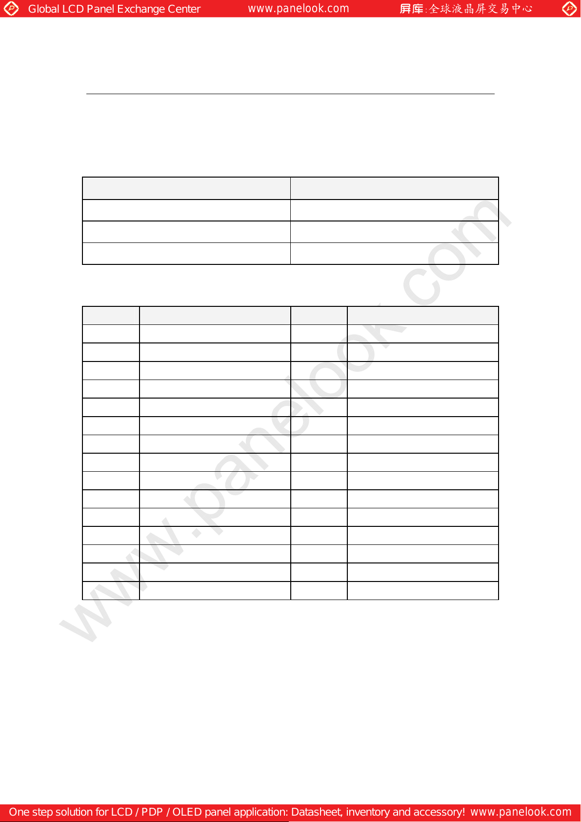
Connector & Pin Assignment
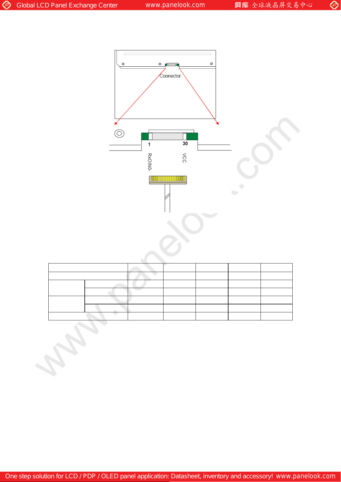
Physical interface is described as for the connector on module. These connectors are
capable of accommodating the following signals and will be following components.
TFT LCD Module
Connector
Connector Name / Designation Interface Connector / Interface card
Manufacturer JST or compatible
Type Part Number FI-XB30SSL-HF15
Mating Housing Part Number FI-X30HL
Pin Assignment
www.panelook.com
Pin# Signal Name Pin# Signal Name
1 RxOIN0 2 RxOIN0+
3 RxOIN1 4 RxOIN1+
5 RxOIN2 6 RxOIN2+
7 VSS 8 RxOCLKIN-
9 RxOCLKIN+ 10 RxOIN3-
11 RxOIN3+ 12 RxEIN0-
13 RxEIN0+ 14 VSS
15 RxEIN1 16 RxEIN1+
17 VSS 18 RxEIN2-
19 RxEIN2+ 20 RxECLKIN-
21 RxECLKIN+ 22 RxEIN3-
23 RxEIN3+ 24 VSS
25 VSS 26 NC
27 VSS 28 VCC
29 VCC 30 VCC
Page 18
One step solution for LCD / PDP / OLED panel application: Datasheet, inventory and accessory!
www.panelook.com
Page 19
Global LCD Panel Exchange Center
Backlight Unit
Physical interface is described as for the connector on module. These connectors are
capable of accommodating the following signals and will be following components.
Connector Name / Designation Lamp Connector / LED Backlight lamp
Manufacturer JST
www.panelook.com
Type Part Number
Mating Type Part Number
Signal for LED Backlight connector
Connector No. Pin No. Input Color Function
CN1
CN2
1 Vcc RED
2 Gnd Black
1
2 Gnd Black
Vcc RED
EHR-2
S2B-EH or Compatible
or Compatible
Positive pole
Negative pole
Positive pole
Negative pole
Page 19
One step solution for LCD / PDP / OLED panel application: Datasheet, inventory and accessory!
www.panelook.com
Page 20
Global LCD Panel Exchange Center
www.panelook.com
CL-X
3.Lightbar Cable:U13239 AWG22 L=180±10mm
2.Lightbar Connector
:EHR-2 or Compatible
1.Outline Tolerance:0.5mm
Note:
Jacky_Kuo
-
2008.3.11
CL-Y
CL-Y
LED Blacklight Power Cable
L=180±10mm
CL-X
mm
VHB,AUO,1954,1000nits,V1,M190EG02 V4, P
1:1 ± 0.5 AU1954E
AU1954 Outline Dimension(M190EG02)
AU1954E(911019545101)
OR Compatible
Herose JAE FI-XB30SSL-HF15
LiteMax
Electronic Inc.
A4 1-1 V1
Connector View
CL-Y
PIN1 PIN30
EHR-2 or Compatible
Positive pole
(RED)
(BLACK)
Page 20
One step solution for LCD / PDP / OLED panel application: Datasheet, inventory and accessory!
Negative pole
-
www.panelook.com
 Loading...