


Listen IR Divisible (Air) Wall Tech Note |
|
|
|||||||
Don’t miss a single sound. |
|
|
|||||||
Using Listen IR Products in Divisible (Air) Wall Applications |
|
|
|
|
|
|
|||
|
|
|
|
|
|
||||
|
|
|
|
|
|
||||
|
|
|
|
|
|
||||
|
|
|
|
|
|
||||
|
Venues |
|
Applications |
|
Listen Product Types Used |
||||
|
• Hotel Ballrooms |
|
• Assistive Listening |
|
• Stationary IR |
||||
|
• Convention Space |
|
• Language Interpretation |
|
• Digital IR |
||||
|
• Places of Worship |
|
• Government handicap |
|
|
|
|
|
|
|
• Other Venues |
|
compliance (USA-ADA) |
|
|
|
|
|
|
Overview
This tech note covers the technology required to design a wireless assistive listening and/or language interpretation system for multiple room divisible (air) wall rooms. In this application, the number and size of rooms changes on an as needed basis. Each new room must provide its own wireless listening/language interpretations system no matter what the configuration.
Example:
The ABC Convention Center has a configurable ballroom system that accommodates up to eight different rooms (see diagram 1). The rooms must be able to be divided into any of the possible configurations. For example, the room must be capable of eight separate rooms, one large room, two medium size rooms (A-D and E-H), etc.
A |
E |
|
|
B |
F |
|
|
C |
G |
|
|
D |
H |
|
|
Diagram 1. Example of an eight room air wall system. The ABC Convention Center requires that any combination of rooms be accommodated.
The core wireless transmission technology to be used is infrared (IR). Wireless FM (RF) technology is difficult to use in this application because of possible interference between the many channels in the area and because the listener would be required to change to the appropriate broadcast channel. A basic requirement this example above is that the listener only needs to turn the receiver on and adjust the volume.
IR offers the following advantages:
1It is secure. This signal is kept within the room.
2All users can use the exact same receiver without changing channels.
3An infinite number of rooms can be employed.
4The system can be used both for assistive listening and for language interpretation
Listen Technologies Corporation • 14912 Heritagecrest Way • Bluffdale • Utah 84065-4818 U.S.A. |
|
|
+1.801.233.8992 • +1.800.330.0891 North America • +1.801.233.8995 fax |
Page |
|
Listen Technologies Corporation All rights reserved 101807 |
||
|

Listen IR Divisible (Air) Wall Tech Note
Don’t miss a single sound.
Designing an Air Wall System Using IR Technology
The first consideration in designing a system is to determine whether you are designing a single channel system or a multiple channel system. For single channel systems, there are two possible design methods and for multiple channel systems, only one of those methods is possible.
Method 1: Single Channel Air Wall System Using Auto-Seek (No RF Switcher)
This method uses Listen’s Stationary IR product type. The auto-seek function of the LR-42/44 receivers is used to automatically search for a transmission channel in the room or area of a room where radiators are active. Four transmission channels are used. When a receiver is in auto-seek, it seeks for an active transmission channel on channels 1, 2, 3 and 4 and then stops on an active channel. When it loses the IR signal, it seeks for another signal on any one of the four channels.
Key Concept: It is important to understand that interference will occur if two different transmitter/radiator combinations are set to the same channel.
Radiators are placed in each room on transmission channels shown in diagram 2. When the air walls are closed all radiators are active and the auto-seek function of the receivers is used to find the channel in any given room. For example, let’s say that one room is on channel 3 and another room is on channel 2. When a user steps into the first room, the receiver will find this channel and lock on to it. When the user goes to the next room, the receiver will unlock from channel 3 and lock on channel 2.
Once air walls are opened, the interior room radiators are turned off by not routing any audio to the corresponding transmitters. When this happens the radiators are deactivated after 30 minutes. The exterior room radiators are designed to radiate enough IR to cover the interior room space.
Summary
1Radiators are placed in each room.
2Radiators in exterior rooms are designed such that when the interior walls are open, they radiate sufficient IR into interior rooms.
3When the air walls are open, the interior radiators must be turned off to prevent interference caused by two different transmission systems on the same channel. Radiators can be turned off (after 30 minutes) by not routing any audio to the corresponding transmitter.
4Receivers are set to auto-seek. In this function, the receivers search for a transmission channel and then locks on to that channel. When the transmission is lost, the receiver unlocks and looks for another transmission channel.
Let’s use an example to design a system for the ABC Convention Center. See diagram 2 and 3 for this discussion.
Refer to the diagram 2 that shows the air walls CLOSED. Rooms A and G are on channel 1, rooms B and H are on channel 2, so on and so forth. Each room has one to two radiators to cover the space. Rooms A, D, E and H have two radiators that are pointed to the interior space so that when the air walls are opened, they radiate enough IR to cover the interior rooms.
Now refer to diagram 3 showing the air walls OPEN. Notice that the radiators in rooms B, C, F and G are tuned off (**because no audio is being routed to their corresponding transmitter) and the radiators in rooms A, D, E and H fill the interior rooms.
|
Listen Technologies Corporation • 14912 Heritagecrest Way • Bluffdale • Utah 84065-4818 U.S.A. |
|
Page |
+1.801.233.8992 • +1.800.330.0891 North America • +1.801.233.8995 fax |
|
Listen Technologies Corporation All rights reserved 101807 |
||
|

Listen IR Divisible (Air) Wall Tech Note |
Don’t miss a single sound. |
|
|
|
|
|
|||
|
|
|
|
|
|
|
|
|
|
|
|
|
|
|
Ch. 1
Ch. 4 Ch. 2


Ch. 3
Ch. 1 |
Ch. 4 |
Ch. 4 |
Ch. 1 |
|
|
A |
|
E |
B |
F |
C |
G |
D |
|
H |
Ch. 3 |
Ch. 2 |
Ch. 2 |
3 .Ch
3 .Ch
Diagram 2. Single channel air wall system using auto-seek, 8 room air wall system with all air walls CLOSED.
|
|
Ch. 1 |
Ch. 1 |
Ch. 4 |
Ch. 4 |
|
|
|
A |
|
E |
|
|
** |
X |
B |
|
F |
X |
** |
** |
X |
C |
|
G |
X |
** |
|
|
D |
|
H |
|
|
|
|
Ch. 3 |
Ch. 3 |
Ch. 2 |
Ch. 2 |
|
Diagram 3. Single channel air wall system using auto-seek, 8 room air wall system with all air walls OPEN.
**These radiators are deactivated. This accomplished by not routing audio to the corresponding transmitter. After 30 minutes, the radiators will be turned off.
Listen Technologies Corporation • 14912 Heritagecrest Way • Bluffdale • Utah 84065-4818 U.S.A. |
|
|
+1.801.233.8992 • +1.800.330.0891 North America • +1.801.233.8995 fax |
Page |
|
Listen Technologies Corporation All rights reserved 101807 |
||
|
Listen IR Divisible (Air) Wall Tech Note
Don’t miss a single sound.
Method 2: Single Channel Air Wall System Using RF Switcher/Distribution Amplifier
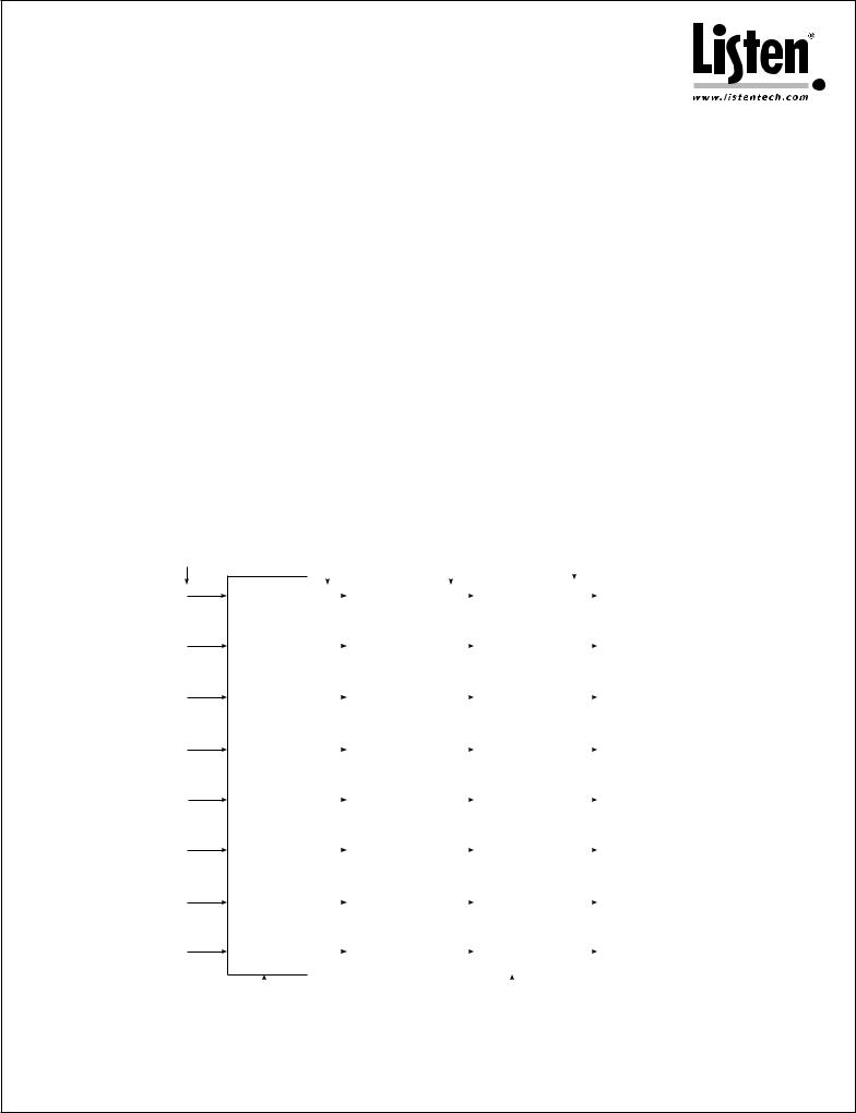
There are four main blocks to designing such a system (see diagram 4):
 IR transmitter (modulator)
 IR radiator (emitter)
 Audio Matrix Mixer
 RF Switcher/Distribution Amplifier (it is possible for the audio matrix mixer and RF Switcher/Distribution Amplifier be the same device)
For each of these blocks, here are the specific products that Listen recommends you use:
 IR transmitter (modulator)
• Listen LT-82
 IR radiator (emitter)
• Listen LA-140
 Audio Matrix Mixer
• No recommendation
 RF Switcher/Distribution Amplifier
• Extron MAV Plus or similar
Diagram 4 shows how to implement the ABC Convention Center for ONE channel. In this case, you would specify a Listen
LT-82 for the transmitter and an LA-140 for the radiators. Multiple channels for language interpretation are shown later in this document.
Microphone mixer output from each room
1
2
3
4
5
6
7
8
|
Audio output from |
RF Output (2-8 MHz) |
RF Output to each |
||||||||||||
|
|
matrix mixer |
from IR Transmitter |
room radiator zone |
|||||||||||
|
|
|
|
|
|
|
|
|
|
|
|
|
|
|
|
|
|
|
|
|
IR Transmitter |
|
|
|
|
|
A |
Radiators |
|||
|
|
|
|
|
(LT-82) |
|
|
|
|
|
|
|
|
|
(emitters) |
|
|
|
|
|
|
|
|
|
|
|
|
|
|
|
|
|
|
|
|
|
|
|
|
|
|
|
|
|
|
|
|
|
|
|
|
|
IR Transmitter |
|
|
|
|
|
B |
Radiators |
|||
|
|
|
|
|
(LT-82) |
|
|
|
|
|
|
|
|
|
(emitters) |
|
|
|
|
|
|
|
|
|
|
|
|
|
|
|
|
|
|
|
|
|
|
|
|
|
|
|
|
|
|
|
|
|
|
|
|
|
IR Transmitter |
|
|
|
|
|
C |
Radiators |
|||
Audio |
|
|
|
|
(LT-82) |
|
|
|
|
|
RF |
|
|
|
(emitters) |
|
|
|
|
|
|
|
|
|
|
|
|
||||
Matrix |
|
|
|
|
|
|
|
|
|
Switcher/ |
|
|
|
|
|
|
|
|
|
|
|
|
|
|
|
||||||
Mixer |
|
|
|
|
|
|
|
|
|
Distribution |
|
|
|
|
|
|
|
|
|
IR Transmitter |
D |
Radiators |
|||||||||
|
|
|
|
|
|
|
|
Amplifier |
|||||||
|
|
|
|
|
(LT-82) |
|
|
|
|
|
|
|
(emitters) |
||
|
|
|
|
|
|
|
|
|
|
|
|
||||
|
|
|
|
|
|
|
|
|
|
|
|
|
|
|
|
|
|
|
|
|
|
|
|
|
|
|
|
|
|
|
|
|
|
|
|
|
IR Transmitter |
|
|
|
|
|
E |
Radiators |
|||
|
|
|
|
|
(LT-82) |
|
|
|
|
|
|
|
|
|
(emitters) |
|
|
|
|
|
|
|
|
|
|
|
|
|
|
||
|
|
|
|
|
|
|
|
|
|
|
|
|
|
|
|
|
|
|
|
|
|
|
|
|
|
|
|
|
|
|
|
|
|
|
|
|
IR Transmitter |
|
|
|
|
|
F |
Radiators |
|||
|
|
|
|
|
(LT-82) |
|
|
|
|
|
|
|
|
|
(emitters) |
|
|
|
|
|
|
|
|
|
|
|
|
|
|
||
|
|
|
|
|
|
|
|
|
|
|
|
|
|
|
|
|
|
|
|
|
|
|
|
|
|
|
|
|
|
|
|
|
|
|
|
|
IR Transmitter |
|
|
|
|
|
G |
Radiators |
|||
|
|
|
|
|
(LT-82) |
|
|
|
|
|
|
|
|
|
(emitters) |
|
|
|
|
|
|
|
|
|
|
|
|
|
|
||
|
|
|
|
|
|
|
|
|
|
|
|
|
|
|
|
|
|
|
|
|
|
|
|
|
|
|
|
|
|
|
|
|
|
|
|
|
IR Transmitter |
|
|
|
|
|
H |
Radiators |
|||
|
|
|
|
|
(LT-82) |
|
|
|
|
|
|
|
|
|
(emitters) |
|
|
|
|
|
|
|
|
|
|
|
|
|
|
||
|
|
|
|
|
|
|
|
|
|
|
|
|
|
|
|
|
|
|
|
|
|
|
|
|
|
|
|
|
|
|
|
|
|
Control |
|
System |
Control |
|
System |
|
|
|
|
|
|
||||
|
|
Diagram 4. Single channel air wall system using RF switcher/distribution amplifier |
|
|||||
|
|
|
|
|
|
|
|
|
|
|
Listen Technologies Corporation • 14912 Heritagecrest Way • Bluffdale • Utah 84065-4818 U.S.A. |
|
|||||
Page |
|
+1.801.233.8992 • +1.800.330.0891 North America • +1.801.233.8995 fax |
|
|||||
|
|
|
Listen Technologies Corporation |
All rights reserved 101807 |
|
|||
|
|
|
|
|
||||
 Loading...