

Listen Technologies LA-122 User Manual

User’s Manual
LA-122 Universal Remote Antenna Kit
Listen T echnologies Corporation
8535 South 700 West, Suite A
Sandy, Utah 84070-2515 USA
Telephone: +1.801.233.8992
Toll-Free (USA): 1.800.330.0891
Fax: +1.801.233.8995
E-mail: info@listentech.com
V.020603. Listen and the Listen logo are registered trademarks of Listen Technologies Corporation. Document #LM-122
Copyright © 2002 Listen T echnologies Corporation. All Rights R eserved.
1
LA-122 Universal Antenna Kit
Mounting Options:
Wall Mount (to your electrical box)
Direct Wall Mount
Ceiling Mount
In-Wall or In-Ceiling Mount
Mast Mount
R
www.ListenTech.com
F
D
E
B
A
Use With:
LT-800-072 Stationary Transmitter
LT-800-216 Stationary Transmitter
LR-100-072 Stationary Receiver /
Power Amplifier
LR-100-216 Stationary Receiver /
Power Amplifier
Optional Accessories
LA-315 Wireless Speaker / Portable
Antenna Stand
LA-127 RG58 BNC Cable Connector
LA-128 RG8 BNC Cable Connector
LA-112 RG58 Coaxial Cable
LA-113 RG8 Low Loss Coaxial Cable
LA-114 Coaxial Connector Installation
(2 connectors)
LA-121 BNC Adapter (LT-800-072 only)
C
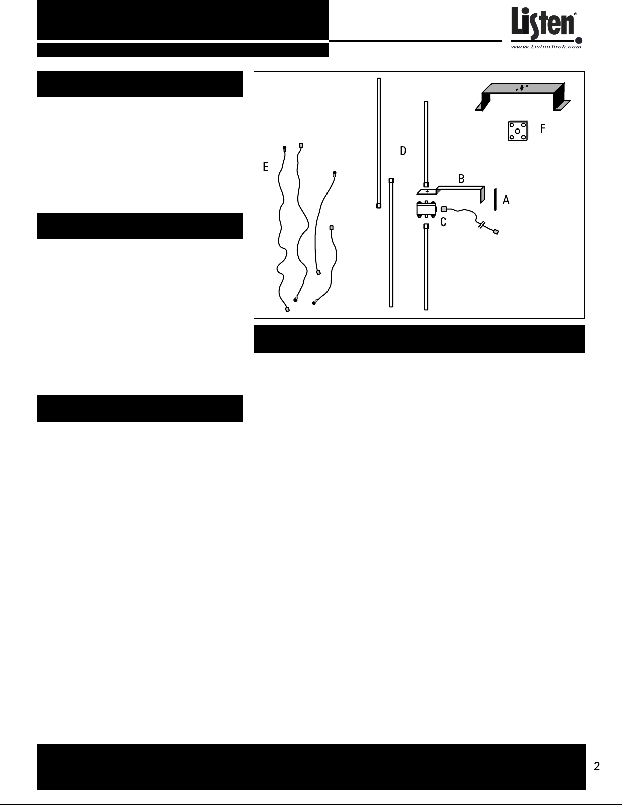
Kit Includes:
A. Wall / Electrical Box Mounting Plate
B. Mounting Bracket
C. Antenna Module and 25 feet (7.6 m) RG58 coaxial cable
with BNC connectors
D. Telescoping antennas (2 for both 72 and 216 MHz)
E. Flexible antennas (2 for both 72 and 216 MHz)
F. Ground Plane and Shorting Plate
G. Mounting Hardware (not shown):
(4) #6-32 Machine Screws - used to mount to a single or
dual gang duplex box
(4) #8-32 Machine Screws - used to mount to a square or
hex junction or light box
(4) #8 Sheet Metal Screws - used to mount to metal or
wood, or for use with dry anchors
(4) Dry Anchors - used to mount to drywall, concrete,
plaster, brick, or masonry
(2) Hex Kep Nuts (#10-32) and (1) Fiber Washer - used for
mounting flexible antennas to the Antenna Module, and
for grounding purposes
Thank you for purchasing this Listen product! If you have any questions or would like
to offer suggestions on future Listen products, please contact us at the address shown
below.
LISTEN TECHNOLOGIES CORPORATION 8535 South 700 West, Suite A Sandy, Utah 84070-2515 USA
Phone: +1.801.233.8992 USA Toll Free: 1.800.330.0891 Fax:+1.801.233.8995 e-mail: info@listentech.com
2

LA-122 Universal Antenna Kit
Table of Contents
Contents of Kit ............................................................................... page 2
Specifications ................................................................................ page 3
Architectural Specifications .......................................................... page 3
Important Things to Note Before Starting .................................... page 4
Selecting an Antenna Location ..................................................... page 6
Choosing Which Antenna to Use .................................................. page 6
Dipole Antenna Mounting Options ................................................ page 7
Monopole Antenna Mounting Options ......................................... page 11
Troubleshooting ............................................................................. page 14
Warranty ......................................................................................... page 16
Specifications
R
www.ListenTech.com
Center Frequencies: 73.50 MHz and 216.50 MHz
Antenna Types: Monopole and Dipole
Antenna Gain: Unity
Antenna Segment Lengths: (same for both rigid and flexible antennas)
Dipole Vertical Clearance: 72 MHz: 79.75 in (2.03 m); 216 MHz: 25.75 in (65.4 cm)
Connector: Standard BNC
Coax Provided: 25 ft (7.6 m) RG58 with BNC connectors
Mounting Options: Wall mount, dual and single electrical box, ceiling electrical box,
Mounting Hardware: Provided. Includes self-tapping sheet metal screws, drywall
Mounting Bracket Dimensions:4.5 in (11 cm) wide x 7.0 in (18 cm) deep x 2.5 in(6.4 cm) high
Mounting Plate Dimensions: 4.48 in (11.4 cm) x 4.55 in (11.6 cm)
Shipping Box Dimensions: 2.76 in x 16.3 in x 17.1 in
Weight: 4.4 Lbs. (2 kg)
Architectural Specifications
72 MHz: 39.25 in (1.0 m); 216 MHz: 12.25 in (31.1 cm)
horizontal surface mount (such as on top of a rack), ceiling /
inverse mounting, flexible mounting in-wall or in-ceiling and
mast or conduit mount
anchors, and all hardware required to mount to electrical boxes.
Does not include hardware required to mount to a mast (available at most hardware stores)
(70 mm x 415 mm x 435 mm)
The Universal Antenna Kit shall be capable of operating from 72.0 to 76.0 MHz with a
center frequency of 73.5 MHz and from 216.0 to 217.0 MHz with a center frequency of
216.5 MHz. The kit shall include the necessary mounting hardware to mount the
antenna on a single or dual electrical box, directly on a wall, on a ceiling electrical box
or on a flat surface. The antenna shall have a BNC connector and the kit shall come
with 25 ft (7.6 m) of RG58 coax with BNC connectors. The kit shall include rigid and
flexible antenna radials. The Listen LA-122 Universal Antenna Kit is specified.
LISTEN TECHNOLOGIES CORPORATION 8535 South 700 West, Suite A Sandy, Utah 84070-2515 USA
Phone: +1.801.233.8992 USA Toll Free: 1.800.330.0891 Fax:+1.801.233.8995 e-mail: info@listentech.com
3
LA-122 Universal Antenna Kit
Important Things to Note Before Starting Your Installation
Coaxial Cable
If you plan to use your own coaxial cable instead of the provided cable, you must use
cable and connectors rated at 50 ohms. Although cable used for cable TV installations
looks similar to this cable, it won’t work with your Listen system.
If you need to run cable over a greater length than 50 feet for 216 MHz applications or
greater than 100 feet for 72 MHz applications, we recommend that you use RG-8 cable
rather than RG-58. It is a lower loss cable, meaning that more of your signal will reach
the antenna.
Long cable runs can result in signal degradation due to “loss” characteristics of the
cable. At 72 MHz, there is a loss of 2dB per 100 feet of cable and at 216 MHz, there is a
loss of 5 dB per 100 feet of cable. (A 3dB loss means half of your power has been lost.)
However,
obstacles! obstacles!
obstacles! Obstacles, especially metal, can create drop-outs or reflections of your sig-
obstacles! obstacles!
nal that will result in poor listening conditions.
it is better to suffer coaxial power loss than to try to shoot your signal throughit is better to suffer coaxial power loss than to try to shoot your signal through
it is better to suffer coaxial power loss than to try to shoot your signal through
it is better to suffer coaxial power loss than to try to shoot your signal throughit is better to suffer coaxial power loss than to try to shoot your signal through
R
www.ListenTech.com
Before Starting Assembly of Your Antenna
Please carefully compare the contents of your kit with the list found on page 2 of
this manual. If any items are missing or damaged, please contact Listen
Technologies. If items were damaged in shipment, contact your carrier immediately and retain all packaging for inspection by your carrier. Listen is not responsible for shipping damage.
Listen TListen T
Listen T
Listen TListen T
8535 South 700 West, Suite A
Sandy, Utah 84070-2515 USA
Telephone: +1.801.233.8992
USA Toll Free: 1.800.330.0891
Fax: +1.801.233.8995
e-mail: info@listentech.com
echnologies Corporationechnologies Corporation
echnologies Corporation
echnologies Corporationechnologies Corporation
LISTEN TECHNOLOGIES CORPORATION 8535 South 700 West, Suite A Sandy, Utah 84070-2515 USA
Phone: +1.801.233.8992 USA Toll Free: 1.800.330.0891 Fax:+1.801.233.8995 e-mail: info@listentech.com
4
LA-122 Universal Antenna Kit
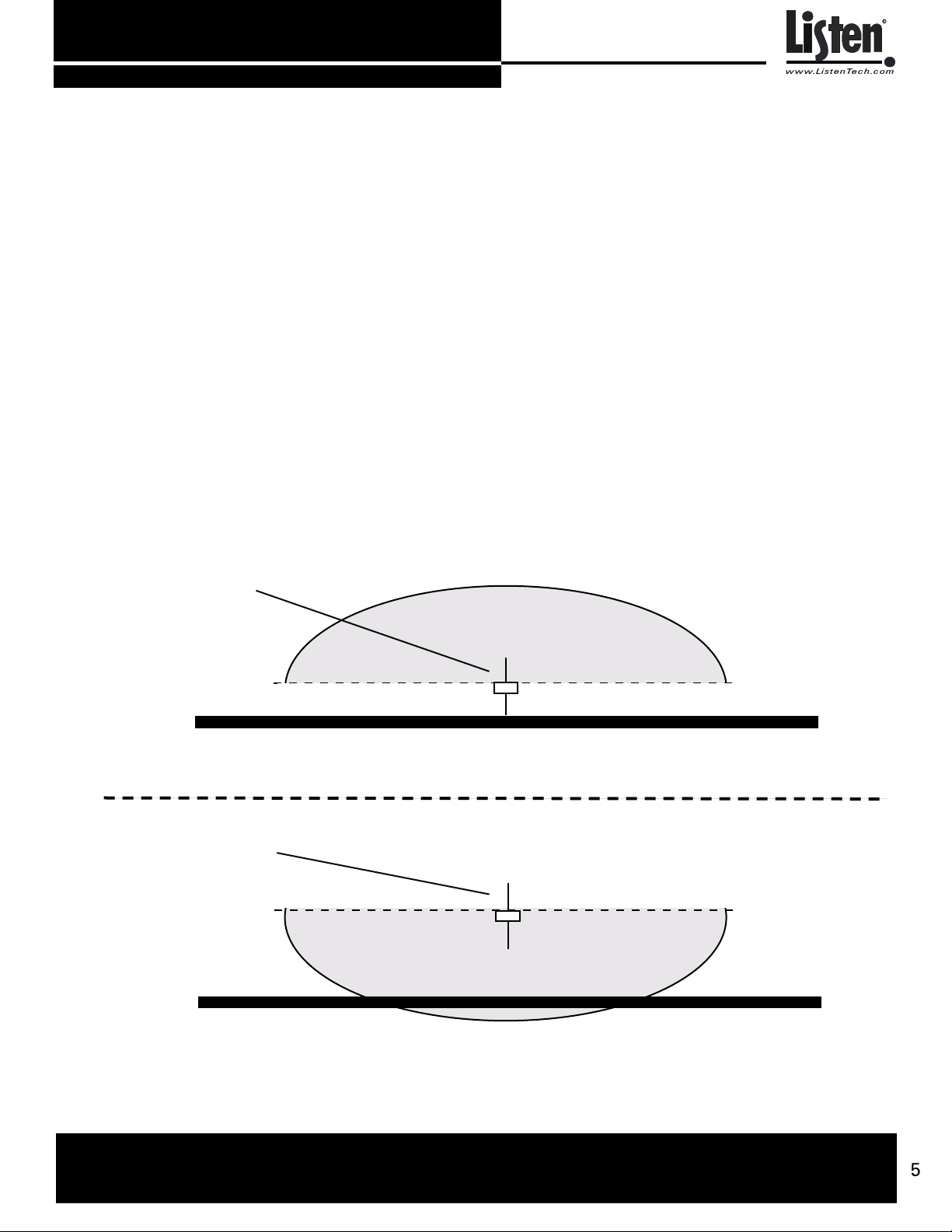
Antenna Orientation
The antenna’s pattern is hemispherical, meaning that it has an “active” side and a
ground side. The active side directs the signal toward the receivers, so it is
essential that the active side be oriented toward the area where the receivers will
be used. The Antenna Module’s ground side has the word “GROUND” molded
into the plastic.
See Diagram A. If it is necessary to locate an antenna low on a wall, the ground
side should face down. If you are mounting a monopole antenna in a ceiling or
high on a wall, the ground side should face UP. It may be necessary to move the
ground side of the antenna mount around in order to accomplish this.
To move the ground side of the module, simply remove the four nuts, reverse the
module so that the ground side is facing the bracket, then re-attach the nuts. Be
careful to not detach any wires if the module opens while it is not secured to the
bracket.
R
www.ListenTech.com
Scenario 1 Antenna is mounted low
in the facility
Scenario 2 Antenna is mounted high
in the facility
This is the area of coverage
Ground side of antenna
Ground side of antenna
This is the area of coverage
Diagram A. Antenna coverage patterns. In Scenario 1, the antenna is mounted low in the facility. The
GROUND side of the antenna (marked on the module) should face down. In Scenario 2, the antenna is
mounted high in the facility. The GROUND side of the antenna should face up.
LISTEN TECHNOLOGIES CORPORATION 8535 South 700 West, Suite A Sandy, Utah 84070-2515 USA
Phone: +1.801.233.8992 USA Toll Free: 1.800.330.0891 Fax:+1.801.233.8995 e-mail: info@listentech.com
5
 Loading...