

Page 1
ILD1000G Installation Handbook
TO PREVENT ELECTRIC SHOCK DO NOT REMOVE THE
Handbook Contents
• Safety
• Introduction
• Quick Start
• Installation
• Overview
• Troubleshooting
• Accessories
• Technical Specifications
• Warranty
• Declaration Of Conformity
SAFETY
This symbol is used to alert the user to important
operating or maintenance instructions.
The Lightning bolt triangle is used to alert the user
to the risk of electric shock.
1. It is important to read these instructions, and to follow them.
2. Keep this instruction manual in an accessible place.
3. Clean only with a dry cloth. Cleaning fluids may effect the equipment.
4. Do not block any ventilation openings. Install in accordance with the
5. Do not install this equipment near any heat sources such as radiators, heating vents
6. WARNING – THIS APPARATUS MUST BE EARTHED / GROUNDED.
7. Only power cords with the correct power connector may be used to maintain safety.
8. Refer all servicing to qualified personnel. Servicing is required when the apparatus
9. WARNING – To reduce the risk of fire or electric shock, do not expose this
manufacturer’s instructions.
or other apparatus that produces heat.
Cables incorporating the UK 13A fused plug, Schuko with earthing contacts and UL
approved “grounding type” are acceptable. These must be plugged into power outlets
which provide a protective earth.
has been damaged in any way, such as a power supply cord or plug is damaged,
liquid has been spilled or objects have fallen into the apparatus, the apparatus has
been exposed to any rain or moisture, does not operate normally or has been
dropped.
apparatus to rain or moisture. The apparatus shall not be exposed to dripping
or splashing and no objects filled with liquids, such as vases, shall be placed
on the apparatus.
Box Contents
1 x ILD1000G
1 x Loop connector
1 x Status socket connector
1 x ‘Installation Handbook’
2 x 1U Rack mounting ears
1 x Power cable
1 x Deaf logo
COVER. THERE ARE NO USER SERVICEABLE PARTS
INSIDE. REFER SERVICING TO QUALIFIED PERSONNEL.
1
Page 2

INTRODUCTION
The ILD1000G Induction loop driver has been designed as a high quality
amplifier for use with conference rooms, stadia, theatres, sports halls,
confidential rooms, lecture halls and cinemas. Depending on a number of
factors regarding the installation of the loop and the set-up of the amplifier
the ILD1000G can provide compliance with IEC60118-4 for areas >1300m2.
Ease of installation and use have been major factors in the design,
combined with optimised performance, and the freedom from R.F.I.
generation.
The ILD1000G has three inputs. A balanced line (INPUT 3), a balanced
microphone (INPUT 1) and one (INPUT 2) which can be configured to either.
For more complex installations, you may need ancillary equipment such as
microphone pre-amplifier(s), adaptor(s) for use with 100V line, or signal
processing units. See Accessories or contact Ampetronic for advice.
QUICK START
For those who have a good appreciation of loop systems, the following is a
very quick guide to setting up the amplifier: All you need is an ac power
source, a signal source and a loop. See ‘Designing Induction Loops’
handbook (supplied) or contact Ampetronic for advice.
Installation
1. Turn all controls fully anti-clockwise.
2. Connect loop cable of appropriate length / gauge.
3. Connect signal input(s).
4. Connect power. See points 6 and 7 in SAFETY section.
5.
If rackmounted remove all rubber feet from units. DO NOT re-fit the
feet fixing screws as this may cause damage and invalidate the
warranty
Operation
6. Switch ON – check green POWER LED flashes during self test and
illuminates continuously when checks are complete.
7. Apply input signal and increase the input control until two green
COMPRESSION LEDs are illuminated on the peaks of the signal.
8. Adjust the CURRENT control until the CURRENT LED illuminate to
achieve the desired peak current.
9. Repeat step 6 for any other inputs used.
10. Listen to the magnetic field produced inside the loop area using a
receiving device (e.g. Ampetronic ILR3), or examine the performance
in more detail with a field strength meter.
11. Adjust MLC control to achieve a flat frequency response.
2
Page 3
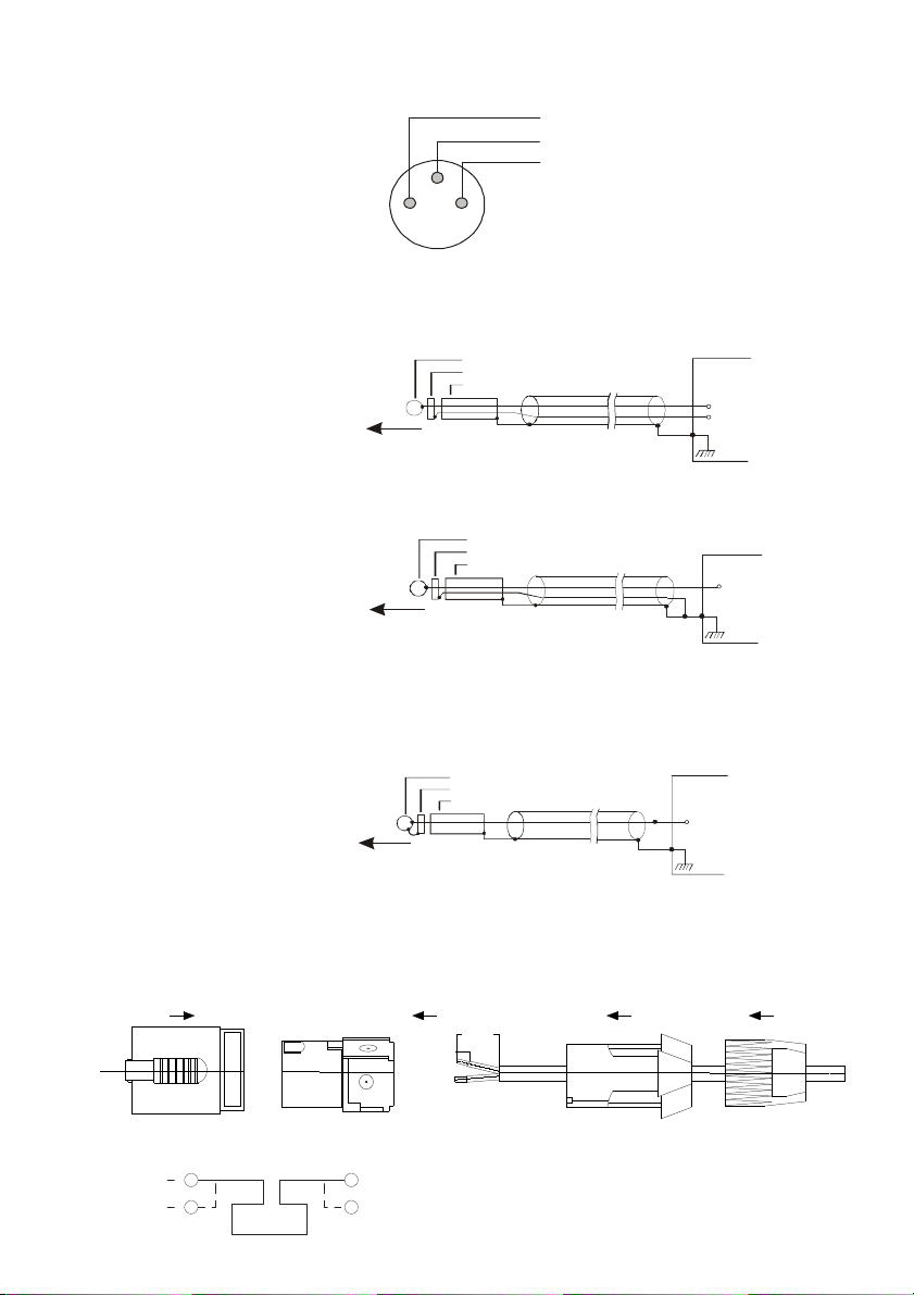
Connections
- (Signal cold)
SOURCE
Connection of 3-pole Plug
CONNECTOR
+ (Signal)
SOURCE
SLEEVE
Connection of 3-pole plug.
RECORDING DEVICE
Connection of 3-pole Plug
INPUT 1 & 2
Screen
+ (Signal hot)
3
1
2
INPUT 3
SLAVE
I/O
Balanced
Unbalanced
Connection of
male XLR
balanced
TIP
RING
SLEEVE
with balanced signals.
Use Twin-screened cable.
TIP
RING
Use Twin-screened cable.
Must be 3m or less.
TIP
RING
SLEEVE
to use Slave I/O socket
for recording output.
+ (Signal hot)
- (Signal cold)
+ (Signal)
LOOP
1
2
LOOP
1+
2+
20.00mm
8.00mm
Refer to technical
specifications for connection
details
3
Page 4
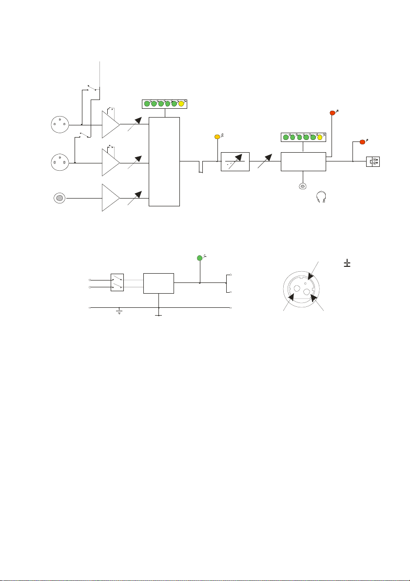
Block Diagram
Must be 3m or less.
Must be 3m or less.
Input 1
Input 2
Phantom
Phantom
Power
Power
Switch
Switch
+15V+15V
Gain Boost
Gain Boost
Compression LEDsCompression LEDs
Input 1 Gain
Overload
Overload
LED
LED
Current LEDsCurrent LEDs
Overheat
Overheat
LED
LED
Loop
Loop
Error
Error
LED
LED
Input 3
230V
or
120V
AC Power
Input 2 Gain
Input 3 Gain
Power
Switch
CompressorCompressor
Power
Supply
Slave
Slave
I/O
I/O
Power
LED
Metal
Metal
Loss
Loss
Correctio n
Correctio n
+15V
-15V
0V
OutputOutput
Current
Monitor
+15V
Use cable supplied.
Use cable supplied.
0V
-15V
Output
Output
15V
150mA
DC
Output
Socket
Loop
Loop
4
Page 5

INSTALLATION
Location
The unit may be free standing or 19” rack mountable using the rack ‘ears’
supplied. Fitting of the ‘ears’ is achieved by removing the two left hand side
for the smaller ‘ear’ and all three right hand side panel screws for the larger
‘ear’. The same screws are then re-used to secure the ‘ears’ in place. (A
PH2 screwdriver will be required). For 19” rack mounting the four rubber
feet must be removed.
The location must provide adequate ventilation for the unit.
An internal fan provides forced ventilation using air vents at the left side
(intake) and rear (exhaust) of the unit. Both of these vents must be
unobstructed for satisfactory cooling. If the unit is installed in an enclosed
environment, sufficient airflow into the enclosure must be provided through
vents fans or other means, such that the units exhaust air is not recycled to
the inlet – causing a reduction in output current or OVERHEAT LED to be
illuminated.
Contact Ampetronic for advice on cooling requirements for your installation.
Tools and Equipment
Small hand tools including a wire stripper and a small flat blade screwdriver
will be required.
An ILR3 loop receiver or a magnetic field strength meter is vital to check
that the loop system is providing the desired level of performance.
A pair of stereo headphones with a 3.5mm jack plug connection is also
useful to monitor the loop signal.
System Requirements
The induction loop cable itself should be already installed according to the
‘Designing Induction Loops’ handbook, or as per specific design instructions
provided by Ampetronic. As a result, a target current should be known,
based on achieving acceptable field strength across the area to be covered.
It is important that the total resistance of loop and feed must be between
0.5Ω and 10Ω (at DC). If this is not achieved, the LOOP ERROR LED will
become illuminated, and the amplifiers output will be disabled. See
Troubleshooting section for details on how correct this, and get your
system working.
The ‘Designing Induction Loops’ handbook contains more details on loop
and feed cables. The correct design and positioning of the actual loop is
vital for satisfactory system performance. If in doubt consult Ampetronic for
advice.
See next page for connection and set-up.
5
Page 6

Connection and Set-up
It is advised that the loop system is initially set up using a local audio source
such as a CD player, which is not connected into any other system. This
avoids the complication of ground loops and feedback etc, whilst the unit is
set up.
The following procedure describes the installation of a stand alone
ILD1000G, and does not incorporate connection of other ancillary units such
as microphone pre-amps, mixing desks, or signal processing units.
1. Turn all controls fully anti-clockwise.
2. Connect the feed cable from the loop into the NL4 loop connector
supplied as shown:
1
2
Note: Where using a perimeter loop (floor/ceiling level), the feed cable
should be tightly twisted to avoid unwanted stray magnetic fields.
3. Connect the signal inputs appropriately:
Microphones: Suitable dynamic or condenser microphone with balanced
cable feed. Select phantom power as required. Connect to INPUT 1 and
INPUT 2 (with selector switch in the appropriate position) using a 3-pole
XLR plug wired as per Connections drawing.
Line level signals: From other audio equipment such as PA system,
mixing desk or CD player. Connect to INPUT 2 (with selector switch in
the appropriate position) using a 3-pole XLR plug and INPUT 3 using a
3-pole balanced jack plug both wired as per Connections drawing
LOOP
1+
2+
.
You may use either or all three inputs.
Do not run input and output cables close together
The SLAVE I/O must NEVER be used as a separate input. It must only
be used with Ampetronic signal processing equipment or for obtaining a
signal for recording. See Connections for details.
4. Connect AC power to the ILD1000G. See points 6 and 7 in Safety
section.
5. Switch ON. The POWER LED will flash for a few seconds whilst an
internal self-test is performed and the loop resistance is tested. If both
tests are successful, the POWER LED will illuminate continuously and
the unit will be in an operational mode. If the POWER LED continues to
flash, or the LOOP ERROR LED illuminates, consult the
Troubleshooting section.
6. Select one input and apply a suitable audio signal (ideally a CD player
6
Page 7

with music or continuous speech applied to INPUT 3, with no connection
to INPUT 1 or INPUT 2). Turn the associated input control clockwise
until two COMPRESSION LEDs are illuminated on the peaks of the
signal.
7. Turn the CURRENT control clockwise until the target current is achieved
– as indicated by the CURRENT LEDs. Note that consecutive LEDs
illuminate at 3dB intervals. Headphones can be used with the MONITOR
socket to listen directly to the loop current. If high frequency oscillation or
low frequency hum is experienced, consult the Troubleshooting
section.
8. The loop system should now be providing a magnetic field inside the
area of the loop – use the ILR3 or field strength meter to examine its
performance with respect to:
a. Magnetic field strength. This may vary across the coverage due to
layout, metal loss and loop current.
b. Frequency response. Metal losses tend to increase with frequency, and
may require the adjustment of the MLC control.
As a result of this analysis, adjust the CURRENT and set the MLC to
achieve the best sound quality. This should result in adequate magnetic
field strength and a level frequency response in order to satisfy
IEC60118-4. Note: Do NOT adjust the MLC control whilst listening to the
MONITOR socket as this will not give a true indication of the response of
the actual loop.
Once the CURRENT and MLC controls have been adjusted to the
correct level they should NOT need re-adjusting.
9. If not already done so, steps can now be taken to integrate the
ILD1000G into a PA / mixer arrangement following standard audio
techniques. If any unusual effects are experienced refer to the
Troubleshooting section.
Note: Ideally, each input signal level should be set up to achieve 6dB
(one LED) of COMPRESSION with the quietest level of input likely to be
used. This will maximize the dynamic range of the system and ensure
satisfactory performance.
10. Repeat the above procedure for each input used. When adjusting each
input, make sure the signals are removed from the other inputs. This
ensures that all signals are set to equivalent loudness and drive the
compressor properly.
7
Page 8

OVERVIEW
COMPR ESSION
dB
INPUT 1
1111
INPUT 1, INPUT 2 and INPUT 3: Screwdriver adjustable controls which set
INPUT 2 INPUT 3
INDUCTION LOOP DRIVER ILD1000G
AC POWER
INPUT 230V
45 - 65Hz
Power: 120W
Fuse: T 1.25A L
Serial Nº
6 1 2 18 24 30 36
CAUTION
RISK OF ELECTRIC SHOCK
DO NOT OPEN
Designed and Engineered in the UK
ML C CURRENT
CURRENT
2.3 3.3 4 .6
A pea k
6.5
9.2 1 3
the level of input signals.
2222
COMPRESSION: Shows the amount of gain reduction in decibels (dB) that
is applied to the input signal(s).
3333
MLC: Screwdriver adjustable control which compensates for the frequency
dependant effects of metal.
4444
CURRENT: Screwdriver adjustable control which sets the level of output
current delivered into the loop.
5555
CURRENT: Indicates the peak current delivered into the loop.
6666
MONITOR: 3.5mm jack socket for use with stereo headphones to listen
directly to the signal being delivered into the loop.
7777
OVERLOAD, OVERHEAT and LOOP ERROR: Warning LEDs, see
Troubleshooting section.
8888
POWER: LED to indicate power is applied to the unit.
9999
I/O: Power switch.
8
MO NITOR
Page 9

0
OVE R
OVE R
LO OP
LOAD
HEAT
ERR OR
POWE R
INDUCTION
LOOP DRIVER
IL D
1000G
I
STATUS
SLAV E I/O
INPU T 3
INPU T 2
SINGLE – TURN
LOOP ONLY
Loop resistance
Min:0.5 Max:3.0Ω Ω
For details consult
instructions or
www.ampetronic.com
1
2
1+
2+
LOOP
AC POWER: Standard 3-pole IEC320 connector containing primary fuse
LOO P OU TPUT
±1 5V
15 0mA
DC
OUTPU T
for the unit.
LOOP OUTPUT: Neutrik ‘Speakon’ High current connection to the loop
cable.
±15V 150mA DC OUTPUT: 3-pin mini DIN connection for ancillary units.
STATUS: Connection to relay contacts providing remote fault indication
SLAVE I/O: 3 pole 6.4mm jack insert point for use with ancillaries.
INPUT 3: 3 pole 6.4mm jack socket for balanced line level inputs.
INPUT 2: XLR socket for balanced MIC/line level signals
LINE/MIC: Mode select switch for input 2.
GAIN BOOST: Gain selector switch for input 2 (ON = +15dB).
PHANTOM: Phantom selector switch for input 2.
INPUT 1: XLR socket for balanced MIC signals
GAIN BOOST: Gain selector switch for input 1 (ON = +15dB).
PHANTOM: Phantom selector switch for input 1.
9
INPU T 1
Page 10

TROUBLESHOOTING
POWER LED not illuminated
• Check that the power switch is toggled to the ON (I) position.
• Check fuse continuity. A 20mm fuse is incorporated into the AC
POWER inlet. It is necessary to remove the power cord before
extracting the fuse holder. Test the continuity of the fuse using a
multimeter. A spare fuse is provided in the fuse holder
Any replacement fuse MUST be of the same rating and type as
printed on the rear of the unit.
POWER LED flashing continuously
Amplifier has failed self test and is in safe mode. No signal will be fed
into the loop. Switch the unit off, remove all connections except the loop
and power connections, turn all front panel controls to minimum and
switch back on. If the problem persists, contact Ampetronic for advice.
COMPRESSION LEDs not illuminating
Check input connections.
Ensure that the appropriate front panel control (INPUT1, INPUT2 or
INPUT3) is turned up. Check there is sufficient signal level for the
required input.
CURRENT LEDs not illuminating
There are many possible causes for this:
• Check the COMPRESSION LEDs are illuminating.
• Check that the CURRENT control is turned up sufficiently.
• Check the LOOP ERROR, or OVERHEAT LEDs are not illuminated.
• Ensure the POWER LED is illuminated and not flashing.
• Remove any connection from the SLAVE I/O socket.
• Check that the loop cable is connected, terminated correctly and
inserted into the LOOP OUTPUT socket.
• Check the loop is not open circuit, short circuit, or connected to
earth (see instability or high frequency noise section of
Troubleshooting)
• Switch the unit off and turn back on.
Note: You can listen to the actual loop signal by using a pair of
headphones plugged into the monitor socket.
10
Page 11

OVERLOAD LED illuminated
Indicates too much current is being delivered into the loop or that the
output voltage is clipping. Occasional lighting of this indicator is normal
on peaks of signal.
• Remove any connection to the SLAVE I/O.
• Turn down the CURRENT control to avoid running too much current
or causing the output voltage to clip.
• Check the loop is not open circuit, short circuit, or connected to
earth (see instability or high frequency noise section of
Troubleshooting)
• Check the loop is within specified limits.
OVERHEAT LED illuminated
Indicates that the internal heatsink is too hot. Loop current is not
delivered.
• Ensure that the unit is installed in a location with sufficient
ventilation
• Check that nothing is blocking the free flow of air through the vents
at the side and back of the unit.
• Check the loop is not open circuit, short circuit, or connected to
earth (see instability or high frequency noise section of
Troubleshooting)
LOOP ERROR LED illuminated
Indicates the loop cable connected to the unit is outside specification.
is important that the total resistance of loop and feed must be between 0.5Ω
and 10Ω (at DC). If this is not achieved, the LOOP ERROR LED may
illuminate and the amplifiers output will be disabled.
Important: Once the cause of any loop error has been established the unit
will need to be restarted. Turn the power OFF - wait 5 seconds, and switch
ON.
It
• Check that the loop cable is connected, terminated correctly and
inserted into the LOOP OUTPUT socket. Restart the amplifier as
above.
• Ensure the DC resistance is acceptable -
between 0.5Ω and 10Ω
. In
all case the amplifier will need to be restarted once the problem is
solved.
Note: Meter leads can easily measure 0.2
Ω, and should be factored out.
• If the loop is open circuit - it may have been cut somewhere and will
11
Page 12

require investigation and potentially re-laying.
• If the loop is high resistance >10Ω - check all connections and re-
tighten, there may be something loose.
• Check for short circuits in the loop connector.
• If the loop is just very low resistance, fold a defined length (see below)
of 0.5mm² cable in half and twist it together neatly – using a hand drill
can be helpful. Coil this loosely on the forearm and bind it so that it
does not come un-coiled. Then connect the two ends in series with the
low resistance loop to ensure that the unit will always turn on, but the
system performance is un-affected. 5m of 0.5mm² wire will add
approximately 0.15 Ω to loop resistance. Use an appropriate length to
ensure the loop resistance exceeds 0.5Ω.
Note: High or low resistance loops can be encountered in a venue with
a pre-installed loop, which was designed for use with an old loop driver
which might be being replaced. Before using this loop ensure that the
existing loop will allow the system to perform to an acceptable level by
checking it’s layout details in the ‘Designing Induction loops’ handbook.
Low magnetic field strength
Due to insufficient CURRENT or excessive metal loss.
May require a special loop design to achieve acceptable performance,
contact Ampetronic for advice.
Instability or high frequency noise
1. It is possible for the loop cable to be grounded under fault conditions,
resulting in instability which may sound like high frequency noise,
buzz or whistling. The results of this type of fault are unpredictable
and may appear as any combination of the front panel indication
errors.
This fault is easy to determine. Simply unplug the loop cable from the
amplifier and test with a resistance meter between either of the loop
wires and a good earth point such as a metal radiator. There should
be an infinitely high reading i.e. no connection at all. Any reading
indicates a failure of the loop cable insulation and you will need to
either repair or replace the loop cable.
2. Instability can be caused by using poor quality signal cables, long
unbalanced (2-wire) signal runs to the inputs, or by running input
cables in close proximity with the loop wire over an appreciable
distance. Loop amplifiers are capable of delivering high currents at
audio frequencies. If the loop cable is run close to sensitive signal
cables it may be possible to induce a signal back into the input of the
amplifier causing feedback. Cable runs and loop wires should be
kept well apart from each other. To avoid interference maintain a
12
Page 13

separation of at least 300mm.
3. Instability can cause the amplifier to run hot and may result in the
OVERHEAT LED illuminating.
Interference
1. Background magnetic field signals or interference may be present in
any location and may not be anything to do with the loop system.
Monitor this with a loop receiver (such as an ILR3). If the interference
is still present with the loop system switched off, then you need to
locate and eliminate the source of the interference before switching
the loop system back on
2. Magnetic fields can induce currents into any low impedance
electrical path or loop. Audio or video systems with multiple earths
may experience pick up of the loop signal. Check entire sound
system for evidence of loop signal, and trace source of pick up.
3. Under certain circumstances, the loop signal may appear as jagged
lines or hum bars on a CCTV picture. This could be due to running
CCTV (low impedance unbalanced 2-wire circuit) cables in close
proximity to the loop cable. Separate the loop cables to reduce the
effect.
4. Remote (and apparently unconnected) PA systems can sometimes
pick up loop signals. This is usually because the loop cable becomes
damaged (see point 1 of Instability) or induces signals into the
remote system through long unbalanced cables. Always run long
audio signal cables as 3-wire balanced circuits and keep away from
loop cables.
5. See also point 1 of Instability
Failed AC power fuse in rear of unit
Unplug the loop and AC power supply from amplifier, and replace the
failed fuse with the spare fuse in AC power input fuse tray.
Reconnect the AC power supply and switch on. If the fuse fails
again, return the unit to Ampetronic for evaluation - it may well be
covered under warranty, which will be invalidated by removing the
cover. If the fuse does not fail a 'loop error' may be indicated, but
shows that the unit is working correctly. Re-connect the loop and
switch the power off then on again to reset loop error.
If the fuse fails when the loop is re-connected to the unit, then the
loop could be shorted to electrical mains (and building) earth. This
can happen even if no audio signal is present, as the short to earth is
likely to cause an instability / oscillation / feedback condition to
develop. A loop cable short to earth most commonly occurs where
13
Page 14

flat copper tape is installed on a metal-clad raised access flooring
system. If the insulation on the flat copper tape is abraded (for
example by a piece of metal swarf trapped below the copper tape),
the conductor could short to the earthed tiles.
When installing on raised access floors, it is advisable to insulate
beneath the flat copper tape installation using Ampetronic PWT or
similar tape.
The loop short to earth may only be completed when a person steps
on the tape in the affected location, which can create significant
difficulties when diagnosing the cause of fuse failure. Contact
Ampetronic for further advice if a unit is suffering recurring but
untraceable failure of the rear panel fuse.
ACCESSORIES
Details of all products and services provided by Ampetronic can be found at
www.ampetronic.co
Wall mount brackets are available for mounting the amplifier on the wall
with appropriate fixings
Microphone pre-amplifiers
Signal processing units are available for use with low spill array systems.
Input adaptors for a range of applications such as 100V line audio and low
Z speaker systems are available.
14
Page 15

TECHNICAL SPECIFICATIONS
INPUTS
INPUT 1;
INPUT 2;
INPUT 3;
AC POWER;
COMPRESSION (AGC)
OUTPUTS
Slave I/O;
LOOP OUTPUT;
Input figures quoted at maximum front panel gain
control setting.
Balanced, XLR connector. 15V
phantom
Suitable source impedance
Input impedance
Sensitivity
Overload
Balanced, XLR connector. 15V
phantom.
Suitable source impedance
Input impedance
Sensitivity
Overload
Balanced line level. 6.4mm jack.
Input impedance
Sensitivity
Overload
Standard IEC inlet
Mains supply voltage
Frequency
Power
Fuse
Inrush current
Compression of signal in dB shown on six front
panel LEDS
Input range
Output range
Min. input level for AGC
Attack time
Decay time
MIC Line
Normal Boost Normal Boost
≤600Ω
1kΩ
-55dBu
-19dBu
≤600Ω
8700Ω
-55dBu
-24dBu
-
-
-
≤600Ω
1kΩ
-70dBu
-34dBu
≤600Ω
8700Ω
-70dBu
-39dBu
-
-
-
-
-
-
8700Ω
-30dBu
1dBu
1MΩ
-30dBu
5dBu
-
-
-
8700Ω
-45dBu
-14dBu
-
-
-
230V (115V)
45–65 Hz
120 W (EN60065 test into square loop)
T 1.25A L (T 2.5A L) - relevant
approvals.
15A (30A)
>36dB
±1dB across input range
Depends on input used (see sensitivity)
8ms
2s
external processors. (out-tip, in-ring, sleevegnd).
connected internally as are 1- & 2- to allow ‘starquad’ method of cable connection).
Current in Amps peak indicated via six LEDs at 3
dB intervals. PPM style processing for display
Insert point for connecting Ampetronic
Source impedance
Input impedance
Output signal level
Max cable length
NL4 speakon (1+ & 2+
Voltage
Current into a single turn loop.
Absolute max short term peak current.
THD +N
Frequency response (loop current)
Metal Loss correction
Attack
Decay
15
220Ω
100kΩ
1.5Vpk
1m
45V peak (31.8V
13A peak (9.2A
RMS
RMS
)
)
>19A
<0.2% @1kHz
80Hz to 6.5kHz ±1.5dB at low level
Adjustable 0 to 3dB per octave (gain
@1kHz remains constant)
4.7ms
1s
Page 16

±15V DC
OUTPUT
;
Max cable length
Status Socket;
PROTECTION
F
EATURES
Clipping
Cooling;
PHYSICAL
Weight;
Dimensions;
Environmental;
Accessories supplied;
Power Mini DIN connector
The status socket consists of a
pair of isolated contacts (plug supplied as
standard).
Amplifier or load fault
Amplifier and load OK
Contact rating
Dielectric strength (coil – contact)
; Any clipping detected is shown on the
front panel OVERLOAD LED. If clipping persists
(>8s of continuous clipping) amplifier will
shutdown and restart.
Threshold
Output DC offset; If DC offset is detected
amplifier will shutdown and restart
threshold
Overheat; (internal heatsink);
Output level reduction
Output mute (illuminates OVERHEAT)
Any of the above faults also cause the status
relay contacts to open.
Current limit; Also provides indication via
OVERLOAD LED
Loop resistance testing; Checks the resistance
of the load on startup is within limits. POWER
LED flashes during this period. The LOOP
ERROR LED illuminates and output maybe
muted if load is outside limits
Startup time
Min resistance
Max resistance
internal variable speed fan. Intake on
left side, exhaust on rear panel
Fan noise
Amplifier thermal emissions
±15V @ 150mA max.
3m
Open
Closed
DC 2A, 28V, 60W
AC 0.5A, 125V, 60VA
1000Vac 50/60Hz
93% of peak output voltage (time
delays applied to prevent nuisance
tripping)
±0.7V DC
88 to 92°C (3dB max)
92°C (output returns at approx. 60°C)
Approx. 20A pk
8s approx.
0.5Ω
10Ω
33dBA at 1m no load
42dBA at 1m EN60065 test signal into
std. square loop load
100W (EN60065 test into square loop)
Width
Height
Depth
Ingress Protection
Operating temperature range
Relative humidity
Rackmount brackets
Mains lead
Loop connector
Status socket connector
3.7kg
430 mm
44 mm
220mm
IP20
0 – 35°C
20 – 90%
Long one for transformer (right hand)
side
Region specific
Neutrik NL4 speakon
Screw terminal plug
16
Page 17

WARRANTY
This product carries a five year parts and labour warranty from date of
shipment from Ampetronic. To qualify for the five year warranty, the product
must be registered at www.ampetronic.co (products/warranty), without
which the warranty will be valid for two years only.
The warranty could be invalidated if the instructions in this handbook are
not followed correctly, or if the unit is misused in any way.
DECLARATION OF CONFORMITY
Manufacturer: Ampetronic Ltd.
U
Farndon Road
Newark
NG24 4XB.
Declares that the product:
Description: Induction Loop Driver
Type name: ILD1000G
Conforms to the following Directive(s) and Norm(s):
Directive 2004/108/EC
EMC: EN55103-1 : 2009+A1:2012 Emission
EN55103-2 : 2009 Immunity
Directive 2006/95/EC
Safety: EN60065 : 2002+A12:2011
Directive 2011/65/EU RoHS
Date: January 2016
J.R. Pieters
Managing Director
Ampetronic Ltd.
nit 2, Trentside Business Village
UP15101-9
17
Page 18

blank
18
Page 19

blank
19
Page 20

blank
20
 Loading...