

Page 1

ListenTech-Note
Doc. # LTN0016 Page 1 of 3 Revision: 06-22-17
Installing Flat Copper Cable
Overview
This tech-note covers the complete installation of Flat Copper Cable under floor covering applications, i.e. carpet,
vinyl, laminate or hardwood and the important steps to follow with floor structures below, concrete and wood. The
document will also cover how to properly transition from flat copper cable to feeder cable and how to route the
feeder cable back to the Hearing Loop driver’s location.
Items Needed:
- Flat Copper Cable (FB1.0, FB1.8, FB3.0)
- PWT Adhesive/Installation Warning Tape
- Feeder Cable (AWG THHN Cable)
Flat Copper Cable Installation:
Prior to the installation, the concrete or wood floor must be completely cleaned and free of dust. The floor should
be flat and free of any imperfections, if imperfections are found, they must be filled in and have a flat finish. This will
provide a clean and flat surface for the PWT tape to adhere to properly preventing damage to the cable overtime.
Concrete floor applications have an additional level of involvement due to the potential of moisture and/or alkalis.
Extended periods of moisture or high levels of alkalis in the concrete pose potential corrosion risks over time, so it is
highly recommended to install one of the following methods to prevent this corrosion potential.
1. PVC Sealant –
a. Glidden GRIPPER® is the PVC based product that provides a barrier between the flat copper cable
and concrete floor and can be found here on Glidden’s website.
b. Sealant is installed using a paint roller method and rolled either over the entire floor or just the
intended* loop locations.
NOTE: It’s recommended to follow the manufactures application methods.
2. Double Sided Carpet Tape –
a. The tape contains adhesive on both sides which provides adhesion directly to the concrete floor
and adhesion for the cable above. The tape is installed directly to the concrete following the
intended* loop locations providing a barrier between the flat copper cable and concrete floor.
*Intended loop locations are determined by the Official Design provided by Listen.
Once floor is prepped and ready, start by marking all loop dimensions following the official design with a permanent
marker on the floor. You can then use a chalk line to mark defined lines to provide straight lines to follow when
laying down the cable.
Proceed to install the cable following the marked lines while either sticking it to the double sided carpet tape and/or
securing in place with the PWT tape. Make turns or angles by gently folding the cable over on itself following the
angle needed, 45, 90 degrees, etc. (see picture below), and press down firmly to create a clean bend. Continue to
follow the official design and/or marked lines to complete the loop system. Depending on design, you may be
required to extend your roll of cable, which is done by soldering on another roll. If required, proceed to the
soldering section of the document.
Page 2
ListenTech-Note
Doc. # LTN0016 Page 2 of 3 Revision: 06-22-17
NOTE: It’s important to make sure that you have sufficient length at the end of your cable run to allow transition to
your feeder cable. Recommended length is around 4 – 5 in.
After cable has been installed, cover and secure it to the floor using the PWT Adhesive Installation/Warning Tape or
similar product. Any overlapping cables within your layout should be covered with PWT to provide a level of
protection from wearing the insulation away, which may cause a short in the loop due to foot traffic.
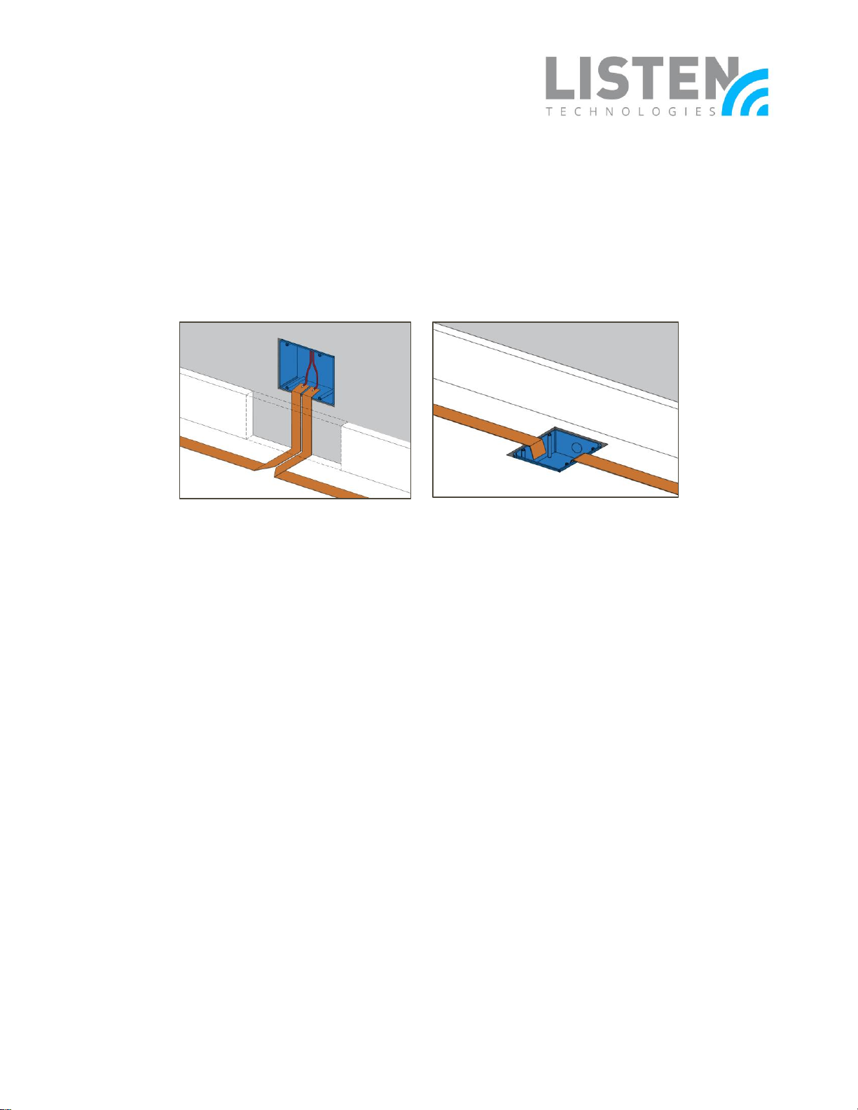
Feeder Cable Transition:
The feeder cable transition is the method of converting the flat copper cable to a gauged cable, which supports the
cable run back to the hearing loop driver’s location. This conversion is handled within gang boxes, and can be
installed in the floor or on the wall. See pictures below.
The feeder cable is then soldered onto the flat copper cable and positioned within the gang box to allow future
access to the connection for maintenance. The feeder cable is then run through conduit back to the driver’s location
and attached to a NL4 SpeakOn connector.
NOTE: Commonly, the feeder cable will be run near other AV cabling, which could cause noise issues within other
equipment if not installed correctly. The below items are recommended to follow during installation of the feeder
cable to prevent those noise issues:
- Feeder cable is essentially an AC power line, which pushes the use of standard audio practices.
o A minimum of 12 – 15 in. of separation when in parallel with other cables.
o Cross at 90 degrees when required.
- Use tightly twisted cable either inherently by the cable manufacturer or the installer using single conductor
cables. This is done to assist in reducing the induction field around the feeder cable portion of the system.
o If a single conductor cable is used, twist cables to meet a recommended 6 – 10 turns per ft. ratio.
o To twist single conductor cables, connect one end of the two cables to a standard drill and
proceed to twist the cables together until turns-per-ft. is met. Secure twist with tape at 5 ft. spans
to prevent unravelling.
Soldering Flat Copper Cable:
Soldering flat copper cable requires a level of skill and practice due to the difficultly to get a reliable solder
connection due to the insulation around the cable and the heat required from a soldering iron. Below is a step by
step process on soldering flat copper cable:
1. Remove half inch to an inch of the insulation by either scraping it away with a knife or melting with a
soldering iron.
2. Apply a generous amount of flux to the scraped or melted area of the cable.
3. Apply soldering iron to cable, once hot, apply solder to cable while moving iron around to cover intended
area.
Page 3

ListenTech-Note
Doc. # LTN0016 Page 3 of 3 Revision: 06-22-17
4. If connecting additional flat copper cable to extend the loop, repeat the previous process on the opposite
side of the cable.
a. Once both cables have been soldered, connect the two soldered ends and apply heat while
pressing together. See pictures below.
NOTE: Pliers or a screw driver is useful in holding and pressing cables together while applying heat.
5. If connecting the feeder cable, strip the feeder cable jacket back about an inch and apply heat using the
soldering iron.
a. Once the cable is hot, apply a generous amount of solder to allow for an easy connection to the
flat copper cable.
b. Once both cables have been soldered, connect the two soldered ends and apply heat while
pressing together. See picture below.
6. Once connection has been made, it’s recommended to test continuity of the connection via a multi-meter.
7. If connection is valid, completely cover connection with electrical tape to prevent short possibilities and/or
moisture from coming into contact with the connection. See picture below.
Should you have additional questions or require further assistance, please contact Listen Technologies at
support@listentech.com or by calling 1-800-330-0890.
 Loading...