

Page 1

QS Series
Master Development System
User's Guide
Page 2
Warning: Some customers may want Linx radio frequency (“RF”)
!
products to control machinery or devices remotely, including machinery
or devices that can cause death, bodily injuries, and/or property
damage if improperly or inadvertently triggered, particularly in industrial
settings or other applications implicating life-safety concerns (“Life and
Property Safety Situations”).
Table of Contents
1 Introduction
2 Ordering Information
2 MDEV-USB-QS Development Board
NO OEM LINX REMOTE CONTROL OR FUNCTION MODULE
SHOULD EVER BE USED IN LIFE AND PROPERTY SAFETY
SITUATIONS. No OEM Linx Remote Control or Function Module
should be modified for Life and Property Safety Situations. Such
modification cannot provide sufficient safety and will void the product’s
regulatory certification and warranty.
Customers may use our (non-Function) Modules, Antenna and
Connectors as part of other systems in Life Safety Situations, but
only with necessary and industry appropriate redundancies and
in compliance with applicable safety standards, including without
limitation, ANSI and NFPA standards. It is solely the responsibility
of any Linx customer who uses one or more of these products to
incorporate appropriate redundancies and safety standards for the Life
and Property Safety Situation application.
Do not use this or any Linx product to trigger an action directly
from the data line or RSSI lines without a protocol or encoder/
decoder to validate the data. Without validation, any signal from
another unrelated transmitter in the environment received by the
module could inadvertently trigger the action.
All RF products are susceptible to RF interference that can prevent
communication. RF products without frequency agility or hopping
implemented are more subject to interference. This module does not
have a frequency hopping protocol built in.
3 Getting Started
3 The USB Area
4 The RS-232 Area
5 The Microcontroller Area
6 The Prototyping Area
7 Installing the Software and Drivers
8 QS Series Master Development System Software
9 Helpful QS Resources
9 In Closing
10 Resources
11 Notes
Do not use any Linx product over the limits in this data guide.
Excessive voltage or extended operation at the maximum voltage could
cause product failure. Exceeding the reflow temperature profile could
cause product failure which is not immediately evident.
Do not make any physical or electrical modifications to any Linx
product. This will void the warranty and regulatory and UL certifications
and may cause product failure which is not immediately evident.
Page 3
QS Series Master Development System
User's Guide
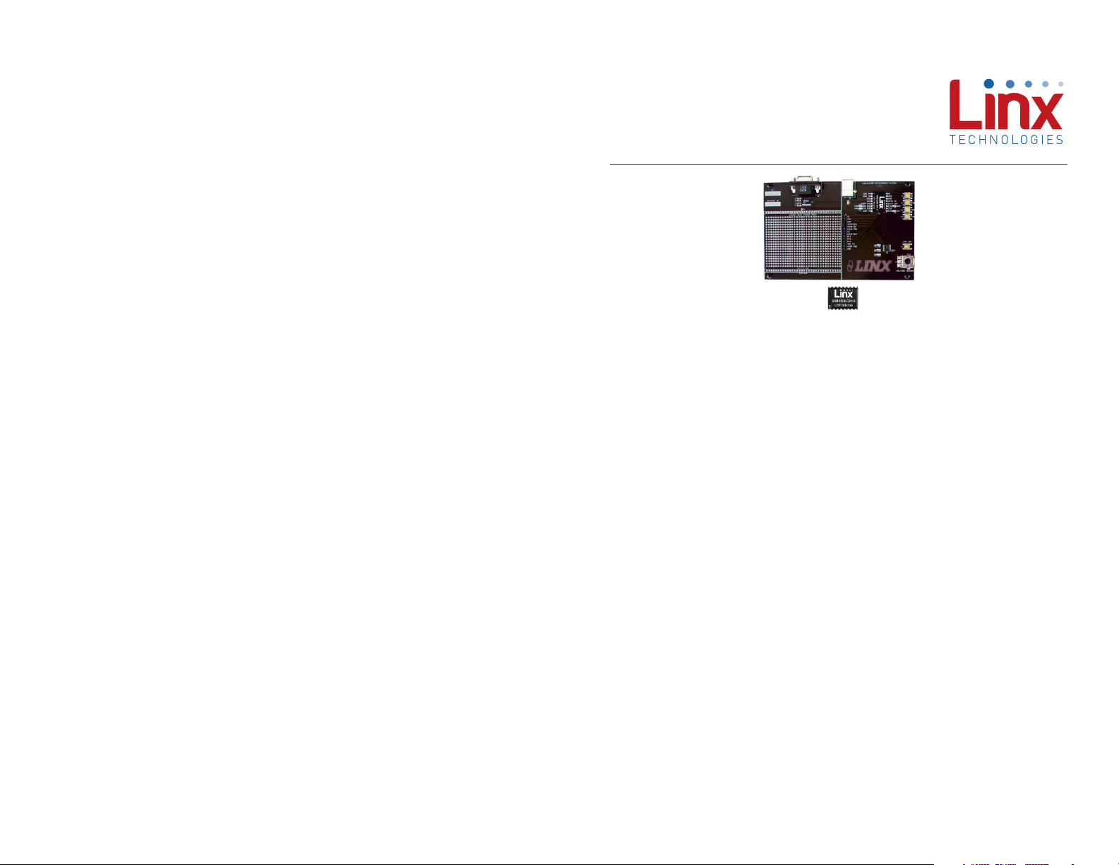
Figure 1: QS Series Master Development System
Introduction
The Linx QS Series USB module allows the rapid addition of USB to
virtually any device. The Master Development System is intended to give a
designer all the tools necessary to incorporate the module into a product.
This guide will show how to take full advantage of the development board
included with the kit. Data guides for all of the Linx parts contained in the
kit are included or may be downloaded from the Linx website. The Master
Development System serves several important functions:
• Rapid Module Evaluation: It allows the module's performance and
features to be quickly evaluated.
• Application Development: It comes with application software and
source code that demonstrate how to interface the module with a
computer. This source code can serve as a starting point for the
development of the product's software.
• Design: It shows how to design with the module and how to interface
with other components.
• Prototyping: It allows for additional circuitry to be placed directly on
the board so that it can act as the first prototype of the product. All of
the signals are available on a wire-wrap header for easy connection to
external circuitry.
The Master Development System Includes 1 development board, 2 QS
Series USB modules*, 1 software CD and full documentation.
*One part is soldered to the board, one extra is for use on your first prototype board
– –
1
Revised 3/18/2015
Page 4
Ordering Information
Ordering Information
Part Number Description
MDEV-USB-QS QS Series Master Development Kit
Figure 2: Ordering Information
MDEV-USB-QS Development Board
1
2
Getting Started
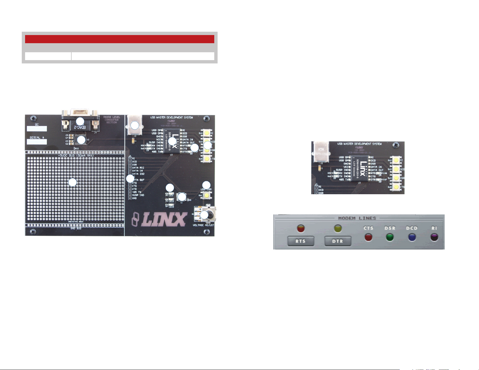
There are four areas on the development board: the USB area, the RS-232
area, the Microcontroller area and the Prototyping area. The RS-232 area
connects the QS module to a standard DB9 serial connector through a
RS-232 level converter chip. This section allows for full handshaking so
that a legacy device can be connected and tested. The microcontroller
section connects the QS to a Microchip PIC microcontroller. The included
software demonstrates how to interface the QS to the PIC for bi-directional
communication with a custom processor. Much of the source code is
documented in the software’s help file.
The USB Area
5
6
7
8
This section demonstrates how to activate the modem outputs and read
the modem inputs. Figure 4 shows the development board and Figure 5
shows the Modem Line section in the development software.
3
Figure 3: The QS Series Development Board
1. DB9 Connector
2. RS-232 Level Converter Chip
3. Prototyping Area
4. Breakout Header
5. USB Jack
6. QS Module
4
10
9
11
12
7. Modem Line Buttons
8. Modem Line LEDs
9. Microcontroller
10. Microcontroller LEDs
11. Microcontroller Button
12. Voltage Adjust Potentiometer
Figure 4: The USB Area
Figure 5: Development Software Modem Line Section
Pressing the RTS and DTR buttons in the software activates the RTS and
DTR LEDs on the development board. Pressing the RI, DCD, DSR or CTS
buttons on the board causes the appropriate indicator on the software
screen to light up. The source code for this is in the software’s Help File.
There are two LEDs to the left of the module, one marked TX IND and
another marked RX IND. These flash when the module is sending and
receiving data, respectively.
Note that the modem lines are designed to work with UARTs, so the states
are inverted. The lines are at VCC when off and at ground when on.
– – – –
2 3
Page 5
The RS-232 Area
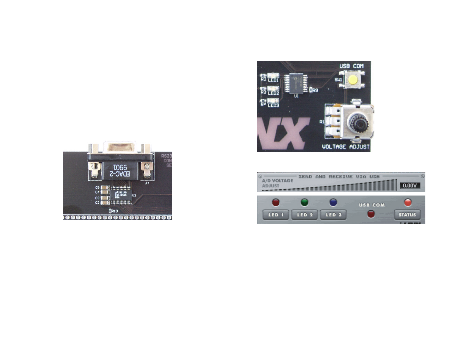
The RS-232 area contains an RS-232 level converter that works with the
QS Series module to create a USB-to-RS-232 converter. All of the modem
lines are provided to allow for full handshaking, and power is provided
by the USB bus. To use, plug the USB cable from the PC into the jack, a
straight-through serial cable from the PC into the DB9 connector and place
the jumper in the breakout header between “Data In” and “Data 232”.
The development software is designed so that testing can be done with
a single PC by sending data through the USB bus and receiving it back
through the serial port and vice versa. This section can also be used to
interface the PC with any RS-232 device. Custom software can be written
to control the device directly, or the Virtual COM Port drivers can be used
to make the USB module look like a serial port so that existing software
can be used.
The Microcontroller Area
The microcontroller area contains a PIC microcontroller from Microchip and
demonstrates how to interface the QS Module with a processor. Figure 7
shows the Microcontroller area on the development board and Figure 8
shows the Send and Receive via USB section in the development software.
Figure 7: The Microcontroller Section
Figure 6: The RS-232 Section
Figure 8: The Software Send and Receive via USB Section
The software sends data to the microcontroller to turn on LEDs when the
user clicks the LED1, LED2 or LED3 buttons on the computer screen. The
microcontroller sends data to the PC to light up the USB COM indicator
on the screen when the USB COM button on the board is pressed. The
microcontroller also sends data to control the A / D Voltage Adjust slider
when the Voltage Adjust knob on the board is turned. Source code
examples are provided with the software documentation to demonstrate
the simplicity of interfacing the QS module with a processor and to aid in
product development.
The USB bus provides all of the power for this section. To use, plug a
USB cable into the jack and the PC, place the jumper in the breakout
header between “Data In” and “Data PIC”, and run the application software
included with the kit.
– – – –
4 5
Page 6
The Prototyping Area
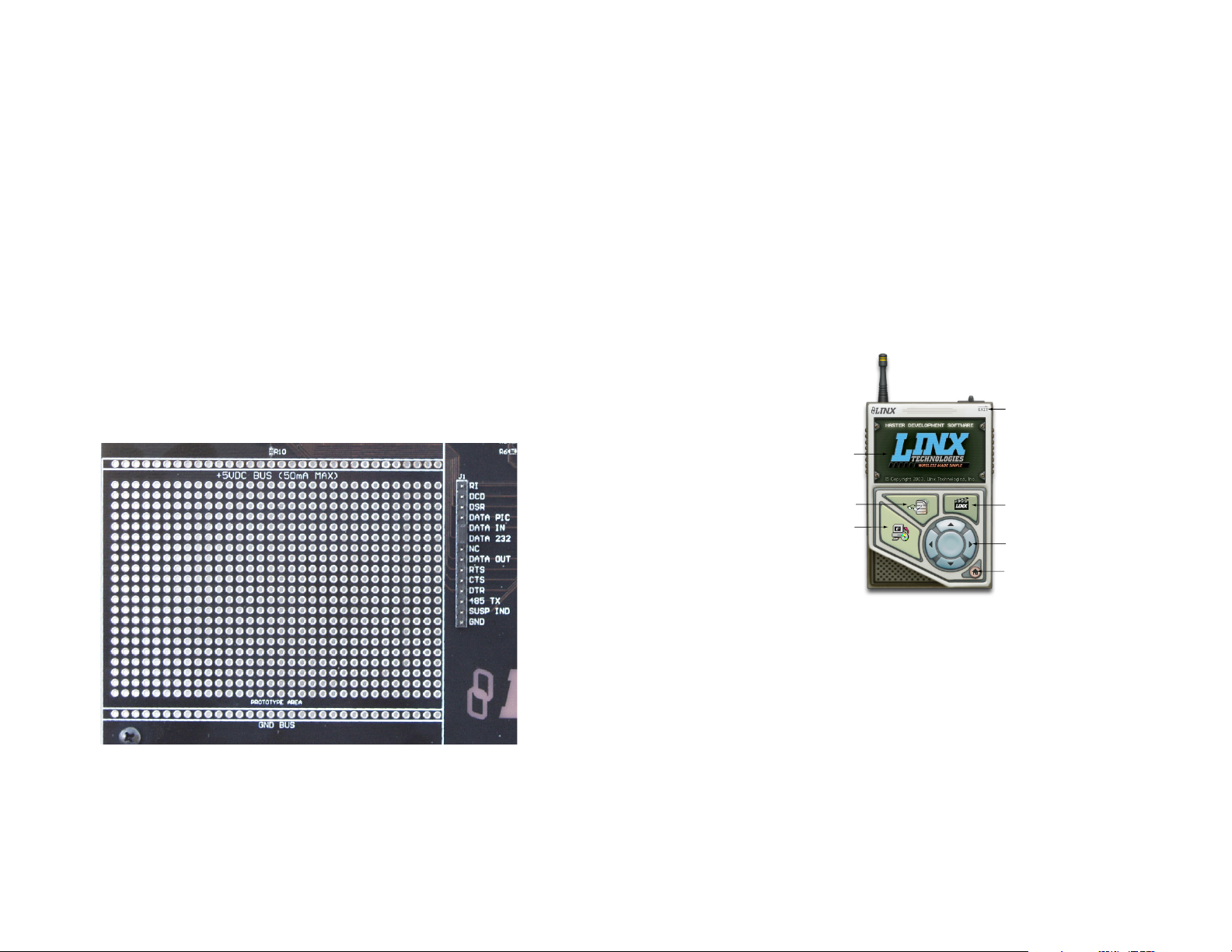
The prototyping area contains an area of plated through holes so that
external circuitry can be placed on the board. This circuitry can be
interfaced with the QS module through the breakout header to the right.
At the bottom of this area is a row connected to ground and at the top is a
row connected to the USB power supply. The circuitry on the development
board draws approximately 40 to 50mA of current, so any circuitry added
to the prototyping area cannot draw more than 50mA before enumeration,
per the USB specification (please see the Power Supply Guidelines in the
module’s data guide for more information). If the circuitry requires more
current, then an external power supply is required.Resistor R10 is a 0-ohm
jumper that can be removed to isolate the power supply row from the USB
supply so that an external supply can be attached to this row.
All of the module’s control and data lines are connected to the header,
allowing easy access from the prototyping area. A jumper is also included
to route the data from the RS-232 Section or the Microcontroller section to
the QS module. It must be appropriately set before the sections will work
properly.
Installing the Software and Drivers
The software included with the Master Development System uses the
Direct Drivers and cannot be used with the Virtual COM Port Drivers. Both
drivers are included on the CD with the software, so be sure to choose the
appropriate one.
The first time a QS module is plugged into a computer, Windows displays
the Found New Hardware Wizard, which guides the installation of the
drivers. Application Note AN-00201 “Installing the SDM-USB-QS-S Drivers”
describes the installation of the drivers in detail. The drivers should be
installed before running the Development Software.
The QS Series Master Development System Software automatically starts
when the CD is inserted and the player in the figure below appears.
Exit
Player Screen
Figure 9: The Prototyping Area
View Documentation
Install Software
Figure 10: Software Installer
Clicking the Install Software button starts the Installation Wizard,
which guides the installation of the development software. The View
Documentation button shows a list of the application notes and manuals
related to the QS module. Selecting one of these opens the file in Adobe
Acrobat. The Play Movie button plays a short video about Linx in the
Player screen, which can be controlled with the Selection Keypad. Clicking
the button on the bottom right of the player opens the Linx Technologies
homepage in the computer’s default browser.
Options listed in the View Documentation list allow for the installation of
Adobe Acrobat Reader so that the documents may be viewed. There is
also the option of installing Flash, which may be required if the Linx video
does not play correctly.
– – – –
6 7
Play Movie
Selection Keypad
Go To The
Linx Homepage
Page 7
QS Series Master Development System Software
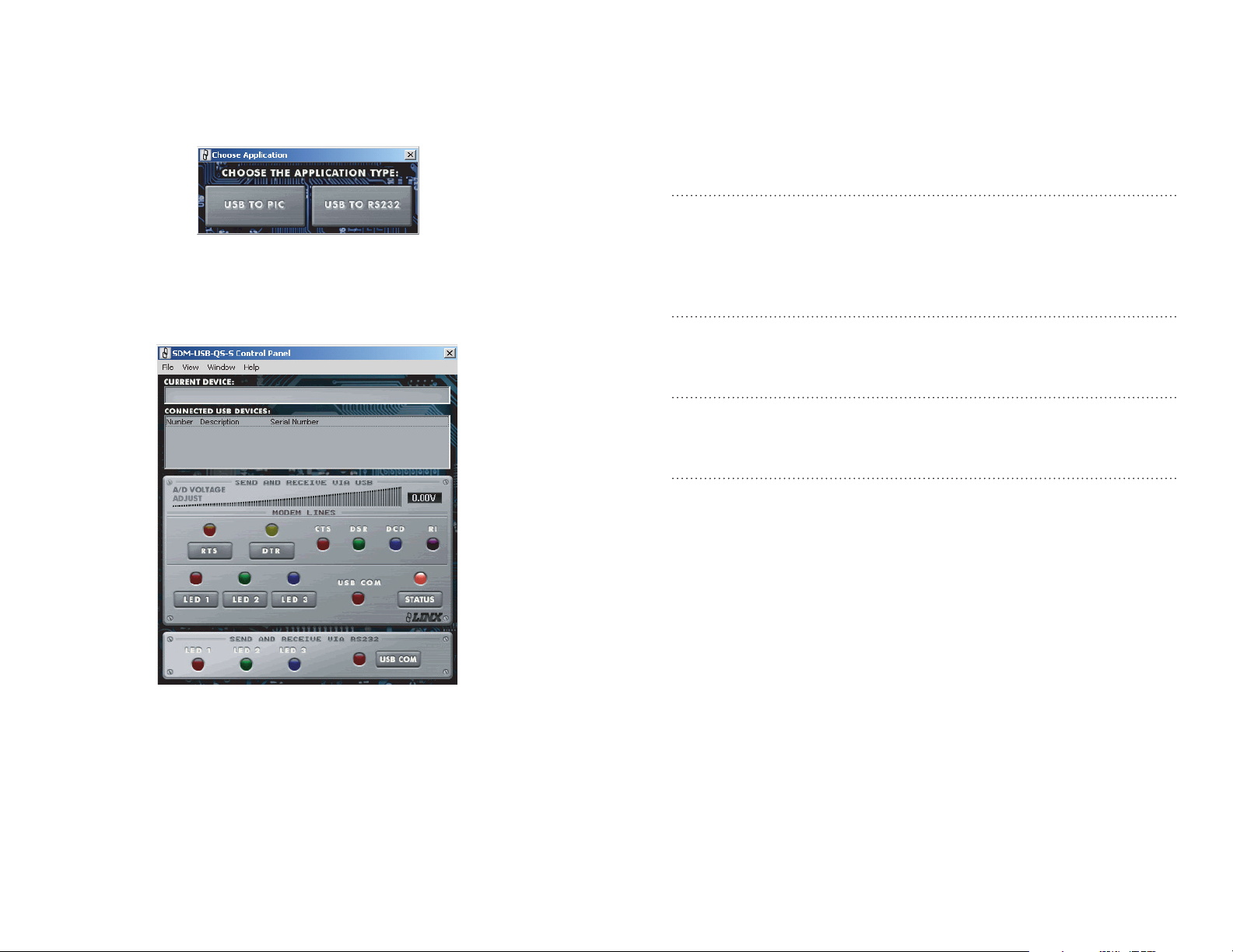
When the software is first started, the screen in Figure 11 prompts the user
to choose which area of the development board will be used with the QS
module: the RS-232 or the PIC section.
Figure 11: The Choose Application Screen
The Control Panel then appears, setup for whichever section was selected.
The area can be changed by going to the Window pull-down menu and
clicking the appropriate selection.
Helpful QS Resources
Below is a list of additional resources available on the development system
CD or for download from the Linx website. These are intended to give the
designer all of the tools needed to quickly and correctly implement the
SDM-USB-QS-S module in a product.
Data Guides
• SDM-USB-QS-S USB Module Design Guide
• Application Note AN-00200, SDM-USB-QS-S Programmer's Guide
• Application Note AN-00201, Installing the Drivers for the
SDM-USB-QS-S
Software
• SDM-USB-QS-S EEPROM Programmer
• SDM-USB-QS-S EEPROM Programmer Manual
Drivers
• SDM-USB-QS-S Direct Drivers
• SDM-USB-QS-S Virtual COM Port Drivers
Function Declarations for Custom Software
• SDM-USB-QS-S Visual Basic Header File
• SDM-USB-QS-S Header File
Figure 12: The Control Panel for RS-232 Operation
Full documentation for the software and samples of the source code
can be found in the help file, obtained by clicking on Help \ Help File and
selecting either the .pdf file to be displayed in Adobe Acrobat or the .html
file to be displayed in the default web browser.
If any problems are encountered, first unplug the module and plug it back
in, then check the help file. If the problem is not corrected or addressed,
then Linx contact information is under the Help \ Contact Us menu.
– – – –
8 9
In Closing
Here at Linx, "Wireless Made Simple" is more than just our motto, it is our
commitment, a commitment to the highest caliber of product, service,
and support. That is why, should you have questions or encounter any
difficulties using the Master Development System, you'll be glad to know
many resources are available to assist you. First, check carefully for
the obvious, then visit our website, www.linxtechnologies.com, e-mail
[email protected], or call +1 800 736 6677 between 7AM
and 5PM Pacific Time to speak with an application engineer.
Page 8
Resources
Support
For technical support, product documentation, application notes, regulatory
guidelines and software updates, visit www.linxtechnologies.com
RF Design Services
For customers who need help implementing Linx modules, Linx offers
design services including board layout assistance, programming,
certification advice and packaging design. For more complex RF solutions,
Apex Wireless, a division of Linx Technologies, creates optimized designs
with RF components and firmware selected for the customer’s application.
Call +1 800 736 6677 (+1 541 471 6256 if outside the United States) for
more information.
Antenna Factor Antennas
Linx’s Antenna Factor division has the
industry’s broadest selection of antennas
for a wide variety of applications. For
customers with specialized needs, custom
antennas and design services are available along with simulations of
antenna performance to speed development. Learn more at
www.linxtechnologies.com.
by
Notes
– – – –
10 11
Page 9

Linx Technologies
159 Ort Lane
Merlin, OR, US 97532
Phone: +1 541 471 6256
Fax: +1 541 471 6251
www.linxtechnologies.com
Disclaimer
Linx Technologies is continually striving to improve the quality and function of its products. For this reason, we
reserve the right to make changes to our products without notice. The information contained in this Data Guide
is believed to be accurate as of the time of publication. Specifications are based on representative lot samples.
Values may vary from lot-to-lot and are not guaranteed. “Typical” parameters can and do vary over lots and
application. Linx Technologies makes no guarantee, warranty, or representation regarding the suitability of any
product for use in any specific application. It is the customer’s responsibility to verify the suitability of the part for
the intended application. NO LINX PRODUCT IS INTENDED FOR USE IN ANY APPLICATION WHERE THE SAFETY
OF LIFE OR PROPERTY IS AT RISK.
Linx Technologies DISCLAIMS ALL WARRANTIES OF MERCHANTABILITY AND FITNESS FOR A PARTICULAR
PURPOSE. IN NO EVENT SHALL LINX TECHNOLOGIES BE LIABLE FOR ANY OF CUSTOMER’S INCIDENTAL OR
CONSEQUENTIAL DAMAGES ARISING IN ANY WAY FROM ANY DEFECTIVE OR NON-CONFORMING PRODUCTS
OR FOR ANY OTHER BREACH OF CONTRACT BY LINX TECHNOLOGIES. The limitations on Linx Technologies’
liability are applicable to any and all claims or theories of recovery asserted by Customer, including, without
limitation, breach of contract, breach of warranty, strict liability, or negligence. Customer assumes all liability
(including, without limitation, liability for injury to person or property, economic loss, or business interruption) for
all claims, including claims from third parties, arising from the use of the Products. The Customer will indemnify,
defend, protect, and hold harmless Linx Technologies and its officers, employees, subsidiaries, affiliates,
distributors, and representatives from and against all claims, damages, actions, suits, proceedings, demands,
assessments, adjustments, costs, and expenses incurred by Linx Technologies as a result of or arising from any
Products sold by Linx Technologies to Customer. Under no conditions will Linx Technologies be responsible for
losses arising from the use or failure of the device in any application, other than the repair, replacement, or refund
limited to the original product purchase price. Devices described in this publication may contain proprietary,
patented, or copyrighted techniques, components, or materials. Under no circumstances shall any user be
conveyed any license or right to the use or ownership of such items.
©2015 Linx Technologies. All rights reserved.
The stylized Linx logo, Wireless Made Simple, WiSE, CipherLinx and the stylized CL logo are trademarks of Linx Technologies.
 Loading...