

Page 1

MT Series
Transcoder Module
Data Guide
Page 2

Warning: Some customers may want Linx radio frequency (“RF”)
!
products to control machinery or devices remotely, including machinery
or devices that can cause death, bodily injuries, and/or property
damage if improperly or inadvertently triggered, particularly in industrial
settings or other applications implicating life-safety concerns (“Life and
Property Safety Situations”).
Table of Contents
1 Description
1 Features
1 Applications
NO OEM LINX REMOTE CONTROL OR FUNCTION MODULE
SHOULD EVER BE USED IN LIFE AND PROPERTY SAFETY
SITUATIONS. No OEM Linx Remote Control or Function Module
should be modified for Life and Property Safety Situations. Such
modification cannot provide sufficient safety and will void the product’s
regulatory certification and warranty.
Customers may use our (non-Function) Modules, Antenna and
Connectors as part of other systems in Life Safety Situations, but
only with necessary and industry appropriate redundancies and
in compliance with applicable safety standards, including without
limitation, ANSI and NFPA standards. It is solely the responsibility of any
Linx customer who uses one or more of these products to incorporate
appropriate redundancies and safety standards for the Life and
Property Safety Situation application.
Do not use this or any Linx product to trigger an action directly
from the data line or RSSI lines without a protocol or encoder/
decoder to validate the data. Without validation, any signal from
another unrelated transmitter in the environment received by the module
could inadvertently trigger the action.
All RF products are susceptible to RF interference that can prevent
communication. RF products without frequency agility or hopping
implemented are more subject to interference. This module does not
have a frequency hopping protocol built in.
Do not use any Linx product over the limits in this data guide.
Excessive voltage or extended operation at the maximum voltage could
cause product failure. Exceeding the reflow temperature profile could
cause product failure which is not immediately evident.
Do not make any physical or electrical modifications to any Linx
product. This will void the warranty and regulatory and UL certifications
and may cause product failure which is not immediately evident.
2 Ordering Information
2 Absolute Maximum Ratings
3 Electrical Specications
4 Pin Assignments
4 Pin Descriptions
6 Overview
7 Transceiver Power Control
8 Transcoder Operation
9 Mode Entry
10 Create Mode
10 Learn Mode
11 Transmit Mode
12 Receive Mode
12 TX ID
13 LATCH Mode
13 Targeted Device Addressing
14 Custom Data Transmission
14 Mode Entry Timings
16 Serial Output
17 Serial Mode
21 Serial Interface Command Set Denitions
22 Serial Interface Connections
26 Transcoder MODE_IND Denitions
27 Legal Considerations
27 Helpful Application Notes From Linx
28 Typical Applications
Page 3

29 Operation with the MS Series
30 Design Steps to Using the MT Series
31 Open Access Mode
35 Recommended Pad Layout
35 Production Considerations
MT Series Transcoder Module
Data Guide
Description
MT Series transcoders are designed for
bidirectional remote control applications. Eight
status lines can be set up in any combination
of inputs and outputs for the transfer of button
or contact states. An automatic confirmation
indicates that the transmission was successfully
received. The large, twenty-four bit address size
makes transmissions highly unique, minimizing
the possibility of conflict between multiple
devices. The MT also outputs the ID of the
originating transcoder for logging or identification.
Recognition of the individual outputs can be easily
defined for each device by the manufacturer or
end user. This allows the creation of user groups and relationships. A Serial
Interface Engine (SIE) is provided, which allows configuration and editing of
the device and control of the transcoder by an external microprocessor or
PC. Housed in a tiny 20-pin SSOP package, MT Series parts feature low
supply voltage, current consumption and selectable baud rates.
0.026
(0.65)
0.013
(0.32)
0.007
(0.18)
Figure 1: Package Dimensions
0.309
(7.85)
0.207 (5.25)
0.284
(7.20)
0.030
(0.75)
Features
• Bidirectional control
• Automatic confirmation
• Secure 224 possible addresses
• 8 status lines
• Serial Interface Engine (SIE)
• Latched and/or momentary
outputs
• Definable recognition authority
Applications
• Keyless entry
• Door and gate openers
• Security systems
• Remote device control
• Transmitter ID output
• Custom data transfer
• Device targeting
• Wide 2.0 to 5.5V voltage range
• Low supply current (370µA @ 3V)
• True serial encoding
• Selectable baud rates
• No programming required
• Car alarms / starters
• Home / industrial automation
• Remote status monitoring
• Paging
– –
1
Revised 3/18/2015
Page 4
Electrical SpecicationsOrdering Information
Ordering Information
Part Number Description
LICAL-TRC-MT MT Transcoder
MDEV-LICAL-MT MT Master Development System
MT transcoders are shipped in reels of 1,600
Figure 2: Ordering Information
Absolute Maximum Ratings
Absolute Maximum Ratings
Supply Voltage V
CC
Any Input or Output Pin −0.3 to V
Max. Current Sourced by Output Pins 25 mA
Max. Current Sunk by Input Pins 25 mA
Max. Current Into V
CC
Max. Current Out Of GND 300 mA
Operating Temperature −40 to +85 ºC
Storage Temperature −65 to +150 ºC
Exceeding any of the limits of this section may lead to permanent damage to the device.
Furthermore, extended operation at these maximum ratings may reduce the life of this
device.
Figure 3: Absolute Maximum Ratings
−0.3 to +6.5 VDC
+ 0.3 VDC
CC
250 mA
MT Series Transcoder Specifications
Parameter Symbol Min. Typ. Max. Units Notes
Power Supply
Operating Voltage V
Supply Current l
At 2.0V V
At 3.0V V
At 5.0V V
CC
CC
CC
Power Down Current l
At 2.0V V
At 3.0V V
At 5.0V V
CC
CC
CC
CC
CC
PDN
2.0 5.5 VDC
340 450 µA 1
500 700 µA 1
800 1,200 µA 1
0.15 1.2 µA
0.20 1.5 µA
0.35 1.8 µA
Transcoder Section
Input Low V
Input High V
Output Low V
Output High V
IL
IH
OL
OH
0.0 0.2 x V
0.8 x V
CC
CC
V
CC
0.6 V
VCC – 0.7 V
V 2
V 3
Input Sink Current 25 mA
Output Drive Current 25 mA
Environmental
Operating Temperature Range –40 +85 °C
1. Current consumption with no active loads.
2. For 3V supply, (0.2 x 3.0) = 0.6V max.
3. For 3V supply, (0.8 x 3.0) = 2.4V min.
Figure 4: Electrical Specifications
Warning: This product incorporates numerous static-sensitive
components. Always wear an ESD wrist strap and observe proper ESD
handling procedures when working with this device. Failure to observe
this precaution may result in module damage or failure.
– – – –
2 3
Page 5

Pin Assignments
1
2
3
4
5
6
7
8
9
10 11
Figure 5: MT Series Transcoder Pin Assignments (Top View)
LICAL-TRC-MT
VCC
D6
D7
CRT/LRN
ENC_SEL
SER_IO
CONFIRM
TR_PDN
TR_SEL
TR_DATA
Pin Descriptions
Pin Descriptions
Pin Number Name I/O Description
1 V
2, 3, 11–13,
17–19
4 CRT/LRN I
5 ECN_SEL I
6 SER_IO I/O
7 CONFIRM O
CC
D0–D7 I/O
Supply Voltage
Status Lines. Each line can be configured
as either an input to register button or
contact closures or as an output to control
application circuitry.
Create / Learn Mode Activation Line.
When this line goes high, the transcoder
enters Learn Mode. If it is held high for ten
seconds, the transcoder clears its memory.
If it goes high while the ENC_SEL line is
high, the transcoder enters Create Mode.
If it goes high while the SER_IO line is high,
the transcoder enters Serial Mode.
Encoder Only Select Line. If this line is tied
high, the MT operates as an encoder only.
If it is tied low, the MT defaults to a decoder
until it is set as a transcoder in Create Mode.
Serial Interface Line. This line is used for
the Serial Interface Engine, which allows
the transcoder to be programmed by an
external device. The transcoder also uses
this line to output the ID of the originating
transcoder, status line states, and custom
data.
Transmission Confirmation Line. This line
goes high when the transcoder receives
a confirmation that its transmission was
received correctly.
GND
D5
D4
D3
LATCH
SEL_BAUD
MODE_IND
D2
D1
D0
20
19
18
17
16
15
14
13
12
Pin Descriptions
Pin Number Name I/O Description
Transceiver Power Control Line. This line
can be used to automatically control power
8 TR_PDN O
9 TR_SEL O
10 TR_DATA I/O
14 MODE_IND O
15 SEL_BAUD I
16 LATCH I
20 GND Ground
None of the input lines have internal pull-up or pull-down resistors. The input lines must
always be in a known state (either GND or VCC) at all times or the operation may not be
predictable. The designer must ensure that the input lines are never floating, either by using external resistors, by tying the lines directly to GND or VCC, or by use of other circuits
to control the line state.
Figure 6: MT Series Transcoder Pin Descriptions
to an external transceiver. When waiting
for data, the transcoder toggles power to
a transceiver at a 10% on to 90% off ratio.
The times are determined by the selected
baud rate.
Transceiver Mode Control Line. This line
toggles an external transceiver between
transmit mode (high) and receive mode
(low).
Transceiver Data Line. This line sends
data to and receives data from an external
transceiver.
Mode Indicator Output. This line switches
when a valid transmission is received, when
Learn Mode or Create Mode is entered, and
when the memory is cleared. This allows for
the connection of an LED to indicate to the
user that these events have taken place.
Baud Rate Selection Line. This line is used
to select the baud rate of the serial data
stream. If the line is high, the baud rate
is 28,800bps, if it is low, the baud rate is
9,600bps. The baud rate must be set before
power up. The transcoder will not recognize
any change in the baud rate setting after it
is on.
Set Latched Outputs. If this line is low, then
the data outputs are momentary (active for
as long as a valid signal is received). If this
line is high, the outputs are latched (when
a signal is received to make a particular
data line high, it remains high until another
transmission is received instructing it to go
low) by default, but individual status lines
can be set as latched or momentary through
the SIE.
– – – –
4 5
Page 6

Overview
Many products and applications call for the transfer of button presses
or switch closures across a wireless link. Traditionally, a remote control
link has operated in only one direction, from a transmitter to a receiver.
The cost associated with transceivers has been too high to practically
implement in low-cost products. With the increasing availability of low-cost
transceiver solutions, bidirectional links are now practical and open a new
world of opportunity.
In a wireless environment, maintaining the reliability and uniqueness of
a transmitted signal is generally of great importance. In a unidirectional
system, IC devices called encoders and decoders are often utilized to
simplify this process. The encoder side turns the status of a number
of input lines into an encoded serial bit-stream output intended for
transmission via an RF or infrared link. Once received, the decoder
decodes, error checks and analyzes the transmission. If the transmission is
authenticated, the decoder’s output lines are set to replicate the states of
the encoder’s input lines.
To accommodate bidirectional links, a new type of device has been
developed. Called a transcoder, this device combines a remote control
encoder and decoder into a single device, and is capable of sending
commands as well as receiving them. It is also able to receive an automatic
confirmation from the remote side indicating that its command was
received.
The Linx MT Series is a revolutionary transcoder product designed for
wireless remote control applications. The same device can be used as an
encoder, decoder, or transcoder and is ideal for both uni and bidirectional
applications and even mixtures of the two. The MT Series is easily
implemented, making it ideal for even the most basic applications, but
its rich feature set also allows it to meet the needs of far more complex
applications. These features include the ability to identify the originating
transmitter, establish user permissions, select output latch modes on a
“per pin” basis, and a powerful serial interface that allows control and
information exchange with external microcontrollers or a PC.
Consider a brief example of how just one of the MT’s innovative features
could be used to transform a relatively simple application, the common
garage door opener. In competitive devices, encoded transmissions
are generally either recognized or denied based on the address. If the
addresses match, the state of all data lines are recognized and output.
The MT Series allows a user or manufacturer to establish a user identity
and profile that determines which inputs are acknowledged. Let’s apply
this capability practically to an example: a three door garage houses
Dad’s Corvette, Mom’s Mercedes, and Son’s Yugo. With most competitive
products, any user’s keyfob could open any garage door as long as the
addresses match. In a Linx MT-based system, each individual keyfob could
easily be configured to open only certain doors (guess which one Son gets
to open!)
While reviewing this data guide keep in mind that it seeks to cover the full
scope of the MT’s capabilities. The implementation for a simple one button
remote is different than a powerful targeted control, command, or status
network. While it is unlikely that all of the features of this part will be utilized
at any one time, their availability provides great design flexibility and opens
up many new opportunities for product innovation.
Transceiver Power Control
The transcoder has the option to control power to an external transceiver
through the TR_PDN line. This line can be connected to a power down or
supply line of a Linx transceiver or a similar input on another transceiver.
This allows the transcoder to power down the transceiver when it is not
required, thereby reducing current consumption and prolonging battery life.
The transcoder pulls the TR_SEL line low to place the transceiver into
receive mode and looks for valid data for 16mS or 32mS, depending on
the baud rate. If data is present on the TR_DATA line, then the transcoder
enters Receive Mode. If no data is present, then the transcoder pulls the
TR_PDN line low to power down the transceiver and goes to sleep for
150ms or 295ms. The “off” time is approximately nine times the “on” time,
resulting in a 10% duty cycle, greatly reducing the transceiver’s current
consumption. However, there may be a lag time from when the transmitting
transcoder activates to when the receiving transcoder responds. The
transcoder enters Receive Mode when it sees a valid packet, so there
would only be a lag for the first packet.
This cycle continues until data is received placing the transcoder into
Receive Mode, until a status input line is taken high placing it into Transmit
Mode, or the CRT/LRN line is taken high placing it into Serial, Learn, or
Create Modes. If a faster response time is desired, then the TR_PDN line
can be left disconnected.
– – – –
6 7
Page 7

Transcoder Operation
When the transcoder powers on for the first time, it looks at the state of
the ENC_SEL line. If the line is high, then the transcoder enters Encoder
Mode and acts like an encoder only. It pulls the TR_SEL line high to set
the transceiver into transmit mode and makes all of its status lines inputs.
The transcoder does not have an address, so one must be created before
normal operation can start.
If the ENC_SEL line is low, then the transcoder enters Decoder Mode and
acts like a decoder only. It pulls the TR_SEL line low to set the transceiver
into receive mode and makes all of its status lines outputs. The transcoder
has not learned any addresses, so it will not respond to any transmissions.
Once a user is learned, the transcoder requires that the transmission have
a valid, learned address before it responds.
The process of creating an address also defines which status lines are
inputs and which are outputs. Once this is completed, if the ENC_SEL line
is high, then the MT Series acts as an encoder only using just the defined
inputs and the address that was created.
If the ENC_SEL line is low, the MT Series enters Transcoder Mode and
uses both the inputs and outputs as well as the address that was created.
In this mode, it can send commands as well as receive commands. It
must go through Learn Mode to learn another device's address before it
responds to transmissions.
Mode Entry
The MT Series transcoders have several modes for configuration and
operation. The different modes are entered based on the logic states of
three lines, as shown in Figure 7.
MT Series Mode Entry Conditions
CRT/LRN ENC_SEL SER_IO Mode
1 0 0 Learn Mode
1 1 0 Create Mode
1 0 1 Serial Mode
Figure 7: MT Series Transcoder Mode Entry Conditions
The activation of the CRT/LRN line begins the process. The transcoder
checks the ENC_SEL and SER_IO lines and enters the modes based on
their states. ENC_SEL and SER_IO should be set to the desired state
before activating CRT/LRN to ensure that the correct mode is entered.
Create Mode is used to give the transcoder a unique address and to set
Control Permissions.
Learn Mode is used to learn another transcoder's address.
Serial Mode is used to communicate with the transcoder using its Serial
Interface Engine (SIE).
– – – –
8 9
Page 8

Create Mode
Create Mode allows the generation of a unique address to ensure the
uniqueness of a transmission and prevent unintentional operation of
devices. The MT Series transcoder allows for the creation of 16,777,216
(224) possible addresses. The assignment of the status lines as inputs or
outputs also occurs in this mode.
Create Mode is entered by holding the ENC_SEL line high and pulling the
CRT/LRN line high. The address is randomized for as long as the CRT/
LRN line is high (the ENC_SEL line is not checked again once the process
is begun). Once the line is pulled low, the resulting address is saved in
memory and the transcoder is ready to accept the status line assignments.
Each line that is to be an input should be pulled high. Any lines not taken
high are set as outputs. There is no requirement for the order in which the
lines are activated or the time between activations as long as all of the
desired lines are activated within the time out period. The transcoder saves
the assignments and goes to sleep when the CRT/LRN line is taken high
again or when it times out after 15 seconds.
Learn Mode
In order for the MT to accept transmissions from a specific transcoder, it
must first learn that transcoder’s address. This is done by taking the CRT/
LRN line high then low to place the transcoder into Learn Mode. Once in
Learn Mode, the MODE_IND line starts switching, allowing for connection
of an LED to provide visual indication that the transcoder is ready to accept
a new address. This continues until the CRT/LRN line goes high again or
until a time-out after 15 seconds.
The transcoder looks for a valid transmission from another transcoder
and records the received address. It also records the status line that was
activated in the Control Permissions. Each status line on the transmitting
side that is authorized to control the receiving transcoder needs to be
activated. The receiving transcoder updates the Control Permissions with
each valid packet that contains a new active status line. It is not necessary
to hold all of the desired status lines on the transmitting side high at the
same time, simply press each one that is to be authorized within the time
out period. When the CRT/LRN line is taken high again or the transcoder
times-out after 15 seconds, the recorded address and Control Permissions
are saved in memory and the transcoder returns to sleep.
The MT Series transcoder can store up to sixty unique addresses in its
memory. If a transcoder is re-learned, its permissions are overwritten. The
transcoder does not create a second instance of the same address. If a
new transcoder is learned while the memory is full, then the transcoder
writes the new address over the first address in memory. It flashes the
MODE_IND line five times to indicate that the memory is full and the next
address learned will overwrite the first. All of the learned addresses are
retained if power is removed from the transcoder.
If the CRT/LRN line is held high for ten seconds, then the transcoder
erases all of the stored addresses from memory. The MODE_IND line goes
high for as long as the CRT/LRN line is high, but after the ten seconds it
goes low. Once the CRT/LRN line is pulled low again, the MODE_IND line
goes high for two seconds to indicate that the memory has been cleared.
Transmit Mode
When any of the status lines that are set as inputs go high, the transcoder
enters Transmit Mode. It pulls the TR_PDN line high to activate the
transceiver, pulls the TR_SEL line high to place the transceiver into transmit
mode, records the states of the status lines, assembles the packet,
and sends it through the TR_DATA line. The transcoder then pulls the
TR_SEL line low to place the transceiver into receive mode and looks for a
confirmation from the remote transcoder. If a valid confirmation is received,
then the transcoder pulls the CONFIRM line high, otherwise it checks to
see if any status line inputs are high.
The transcoder continues this for as long as any of the status line inputs
are high, updating the states of the status lines with each transmission.
Once all of the input lines are pulled low, the transcoder finishes the
current transmission, pulls CONFIRM and TR_PDN low to deactivate the
transceiver, and goes to sleep.
The MT has the ability to control the status line byte through the SIE. An
external microcontroller or PC can be used to write the desired input states
and a packet counter into the transcoder. The transcoder uses this byte
instead of looking at the status line inputs, sends the specified number of
packets, then goes to sleep. This is subject to the I/O settings, so lines set
as outputs cannot be set high.
– – – –
10 11
Page 9

Receive Mode
When a rising edge is seen on the TR_DATA line, the transcoder enters
Receive Mode. It then looks for a valid packet, meaning that there are no
errors and that the received address matches one that is saved in memory.
In addition, if Targeted Device Addressing is enabled, then the received
targeted address must match the transcoder’s local address. If no valid
data is received within 16 or 32ms (dependent on the selected baud rate)
then Receive Mode is exited. If there is a match, then the transcoder
pulls the MODE_IND line high as an indication that a valid signal has been
received. It compares the received commands to the Control Permissions
associated with the transcoder that sent the signal, and reproduces the
states of the authorized status lines on the originating transcoder on its
own status line outputs.
If Confirmation is enabled, the transcoder pulls the TR_SEL line high to
place the transceiver into transmit mode and sends a confirmation to the
originating transcoder. It also outputs the ID of the originating transcoder, a
Command Byte that represents the states of the status lines, and a custom
data byte programmed by the user. It then looks for the next valid data
packet. If, at any time, an error or an unknown address is detected, then
the transcoder ignores the packet and looks for the next one. If the 131ms
timer runs out before any valid packets are received, then the transcoder
goes back to sleep.
TX ID
The transcoder outputs an eight-bit binary number on the SER_IO line
to identify which learned transcoder sent the transmission. The number
normally corresponds to the order in which the transcoder was learned,
so the first transcoder learned gets number ‘1’, the second gets number
‘2’, and so on. An exception arises when the memory is full, in which case
the first numbers are overwritten as described in the Learn Mode section.
An exception also arises if the serial interface is used to write an address
to a specific location in memory. The TX ID is output with the Status and
Custom Data bytes after every valid packet that is received, as described in
the Serial Output section.
LATCH Mode
The transcoder has two output options based on the state of the LATCH
line. If the line is low, then all of the status line outputs are momentary,
meaning that they are high for as long as a valid signal is received. Once
the signal stops and the transcoder times out, the lines are pulled low.
If the LATCH line is high, then the transcoder uses a Latch Mask on the
outputs. By default, all of the status line outputs are set to latch, so the
transcoder pulls a data line high upon reception of a valid signal and
holds it high until the signal is received a second time, at which point the
transcoder pulls it low. The transcoder must see a break and time out of
Receive Mode between valid transmissions before it toggles the outputs.
The Latch Mask can be changed through the SIE so that individual status
lines can be set as latched or momentary. The Serial Mode section has
more information on the SIE.
Targeted Device Addressing
One of the powerful features of the MT is Targeted Device Addressing.
This is the ability to target the specific device that is to acknowledge the
transmission. This is accomplished by entering the address of the target
device through the SIE. For example, if a master controller needs Device
10 to activate, a microcontroller or PC can be used to program the address
of Device 10 into the transcoder in the master controller. The transcoder
then broadcasts that address with the commands, and only Device 10
responds. This enables many types of master-slave, peer-to-peer, and even
basic networking systems to be quickly realized. The simple command
set and open architecture allow such systems to be implemented in many
ways. Application Note AN-00157 goes into this feature in more detail.
Targeted Device Addressing only needs to be enabled on the transmitting
side. The receiving side identifies the packet as a targeted packet and
responds appropriately. This option is disabled by default.
– – – –
12 13
Page 10
Custom Data Transmission
The MT Series offers the option of sending one byte of custom data with
the command packet. The custom byte is entered into the transcoder
through the SIE using the Read and Write Custom Data Value commands.
This option is enabled or disabled using the Enable and Disable Custom
Data commands. The custom data byte is output on the receiving end with
the TX ID and Status bytes. Custom Data Transmission only needs to be
enabled on the transmitting side. The receiving side identifies the packet
as containing custom data and outputs the byte. This option is disabled by
default and the receiving transcoder outputs a value of 0xFF for the custom
byte.
This feature is useful for sending an 8-bit A/D value from a sensor, custom
command codes, or an additional user-defined ID for additional proprietary
system authentication. There are no restrictions on the 8-bit value, though
0xFF is not recommended for use since that is the default value with no
data.
Create Mode
CRT/LRN
ENC_SEL
120µs min
Time t does not matter as
long as ENC_SEL goes
high before CRT/LRN.
Figure 8: MT Series Mode Entry Timings
D0 - D7
TR_PDN
TR_SEL
t
(35ms typ)
CRT/LRN
ENC_SEL
Learn Mode
120µs min
(35ms typ)
The Custom Data is output with the Status and TX ID bytes, as described
in the Serial Output section.
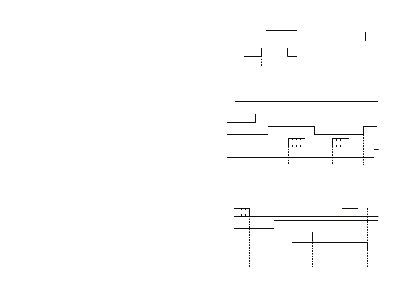
Mode Entry Timings
The transcoder may enter the desired mode within minimum timings
shown in the figure below. However, if the transcoder is in another mode
at the time the CRT/LRN line goes high, then it could take longer for
the transcoder to recognize the trigger. For example, Receive Mode at
9,600bps can take 32ms to exit. For this reason, it is recommended to
increase the time to ensure that the transcoder enters the correct mode.
Typical times are shown in Figure 8, Figure 9 and Figure 10, but may be
adjusted according to the application.
TR_DATA
CONFIRM
Figure 9: MT Series Transmit Timings
TR_DATA
MODE_IND
SER_IO
TR_SEL
D0 - D7
Output Input Output
80µs 20µs 765µs
Data In
Input
520µs to 2.3ms
(depends on user
placement in memory)
5µs
Data Out
10µs 32µs560µs
Depends on
features and
baud rate
Output Input
15µs
50 to 75µs
(depends on
Latch Mask)
Depends
on receiver
15µs
1.39 to 6.25ms
(depends mode
and baud rate)
Confirm
3.4 to 8.0ms
(depends on
baud rate)
Confirm
640µs
3.4 to 8.0ms
(depends on
baud rate)
10µs
Figure 10: MT Series Receive Timings
– – – –
14 15
Page 11
Serial Output
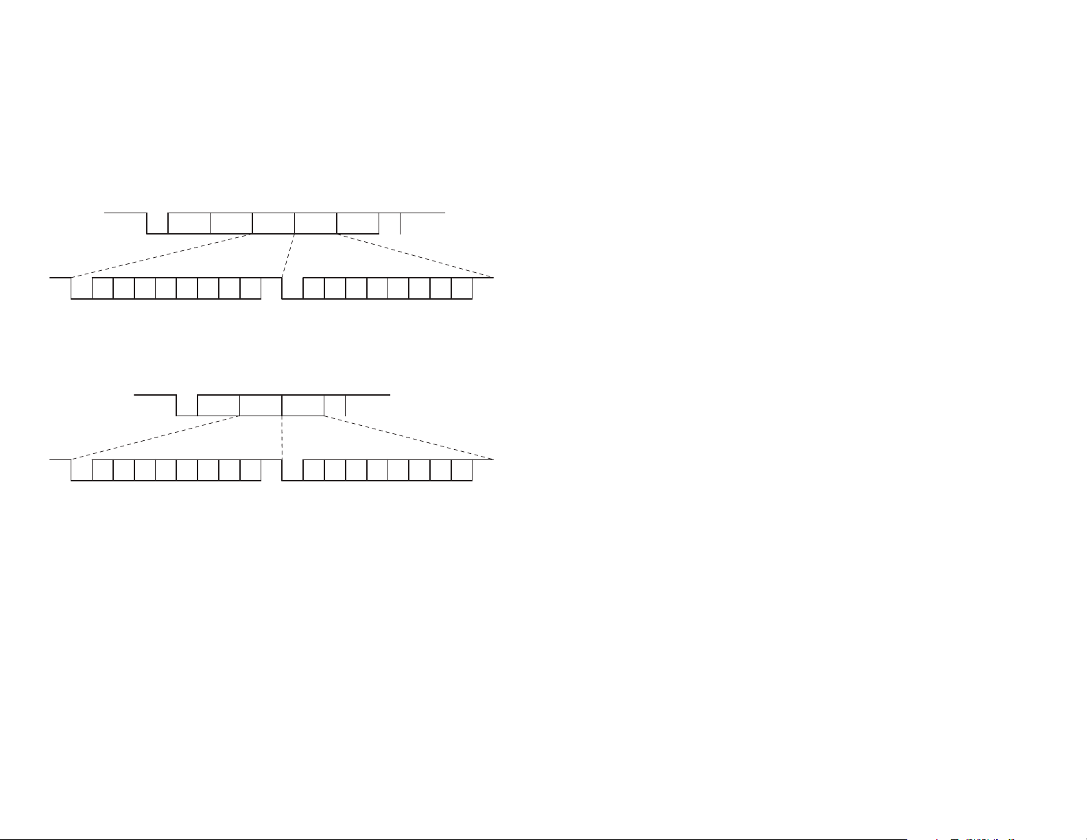
Upon reception of every valid packet, the transcoder outputs a serial data
stream containing information about the transmission. The information
takes two forms depending on the User Access setting.
If the User Access is set to open, then the serial output consists of a start
byte, the three byte address of the transmitting device, a status line byte, a
custom data byte and a stop byte. The start byte is 0x00 and the stop byte
is 0xFF.
ADR 1 ADR 2
SER_IO
b0 b1 b2 b3 b4 b5 b6 b6b7 b7b0 b1 b2 b3 b4 b5
start stop start stop
Figure 11: MT Series Transcoder Open Access Serial Output
00
If the User Access is set to locked, then the serial output consists of a start
byte, TX ID byte, status line byte, custom data byte and a stop byte. The
start byte is 0x00 and the stop byte is 0xFF.
TX ID STATUS CUSTOM FF
SER_IO
00
ADR 3 STATUS CUSTOM FF
Application Note AN-00157 shows some example software to read the TX
ID and associate it with a particular transcoder.
This feature is useful in applications that need to track and record activation
attempts. The transcoder validates that the command is from an authorized
transmitter and an external microcontroller or PC can record the TX ID and
status line activation and time into a log. The Custom byte can also be
used as an additional validation or to send a sensor reading that also needs
to be logged.
Serial Mode
One of the most powerful features of the MT Series is its Serial Interface
Engine (SIE). The SIE allows the user to monitor and control the device
configuration settings through an automated system or PC rather than
manually through the hardware lines. While serial programming is not
required for basic operation, it enables the advanced features offered
by the MT, such as Targeted Device Addressing and Custom Data
transmissions.
The SIE consists of twenty commands. The transcoder outputs an
acknowledgement once it has received each command, and then a
response of up to four additional bytes if required by the command.
b0 b1 b2 b3 b4 b5 b6 b6b7 b7b0 b1 b2 b3 b4 b5
start stop start stop
Figure 12: MT Series Transcoder Locked Access Serial Output
The status line byte reflects the states of the status lines, ‘1’ for high
and ‘0’ for low. This represents the current logic states of the outputs,
not the command that was received, so that the states of latched lines
are correctly represented. Line D0 corresponds to bit b0 in the byte, D1
corresponds to b1, and so forth. This allows applications that use an
embedded microcontroller to read the transmitted commands without
having to monitor eight hardware lines.
The TXID and Custom Data bytes are described in their own sections.
The bytes are output asynchronously least significant bit first with one
start bit, one stop bit, and no parity at the baud rate determined by the
SEL_BAUD line. During normal operation, the SER_IO line is an input,
becoming an output only when sending the data stream or responding to a
serial command. These are described more in the Serial Interface section.
– – – –
16 17
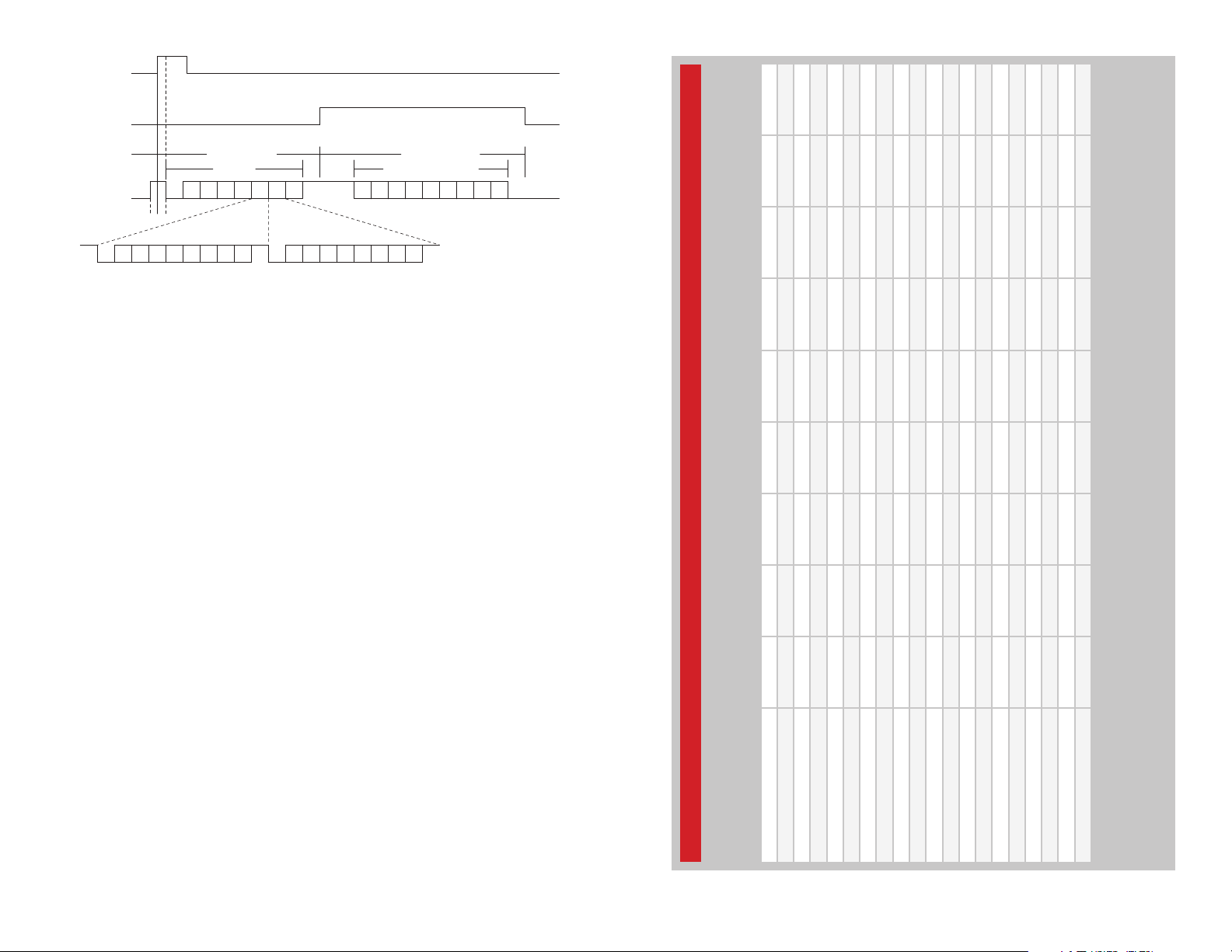
Serial Mode is entered by taking the CRT/LRN line high while the SER_IO
line is high. The MODE_IND line goes high for as long as the SER_IO line
is an output, allowing it to be used with RS-232 style handshaking. Each
byte is sent LSB first with one start bit, one stop bit, and no parity at the
baud rate determined by the SEL_BAUD line. After the last command byte
is received, there is a 1ms pause while the SER_IO line is changed to an
output, then a 4ms pause while the transcoder processes the command.
Then it outputs the acknowledgement and a response if appropriate. The
SER_IO line is changed to an input as soon as the MODE_IND line drops
after the acknowledgement is sent. Figure 17 shows the order and timing
of the serial interface.
Page 12
CRT/LRN (INPUT)
MODE_IND (OUTPUT)
SER_IO = INPUT SER_IO = OUTPUT
Command Acknowledge/Response
SER_IO (INPUT/OUTPUT)
start stop start stop
b0 b1 b2 b3 b4 b5 b6 b6b7 b7b0 b1 b2 b3 b4 b5
00 00 R
t
1t2
1mSCCCCCCFF 4mS AAAR RRFF
Figure 13: MT Series Transcoder Serial Programming
Time t1 in the figure above does not have to be any specific time, just
so long as the SER_IO line goes high before the CRT/LRN line. Time t2
should be greater than 120µs (typical of 35ms, see the Mode Entry Timings
section) to ensure that the transcoder goes into Serial Mode. There is not a
maximum time specified. Once in Serial Mode, the transcoder waits for the
start byte (0x00) of the serial command.
The timings associated with each command and the transcoder’s response
are listed in Figure 14 (9,600bps) and Figure 15 (28,800bps).
To send consecutive commands, keep the CRT/LRN line high and take the
SER_IO line high within 50µs of the MODE_IND line going low.
Time
Max Total
Time
Min Total
Finish
Process
Reply
Transmit
Wait
Reply
Cmd
Process
Cmd
Receive
It should be noted that all of the settings are written into non-volatile
memory, so they are retained if power is removed from the chip. This
includes all values, such as custom byte and target address, as well as the
enabled / disabled states.
– – – –
18 19
SER_IO = Input SR_IO = Output
Max
Ready
Ready
Definition Min
MT Series Transcoder Serial Interface Engine Timings (ms) at 9,600bps
Read Local Settings 0.08 33.00 8.30 1.11 4.00 9.58 0.04 23.11 56.03
Write Local Settings 0.08 33.00 8.30 1.03 4.00 5.29 17.89 36.59 69.51
Read Next User ID 0.08 33.00 8.30 1.06 4.00 6.38 0.04 19.86 52.78
Write Next User ID 0.08 33.00 8.30 1.04 4.00 5.29 3.65 22.36 55.28
Read Specific User 0.08 33.00 8.30 1.11 4.00 9.58 0.04 23.11 56.03
Write Specific User 0.08 33.00 8.30 1.04 4.00 5.29 14.30 33.05 65.93
Read Target Address 0.08 33.00 8.30 1.10 4.00 8.51 0.04 22.03 54.95
Write Target Address 0.08 33.00 8.30 1.05 4.00 5.29 10.74 29.46 62.38
Read Custom Data Value 0.08 33.00 8.30 1.07 4.00 6.38 0.04 19.87 52.79
Write Custom Data Value 0.08 33.00 8.30 1.05 4.00 5.29 3.65 22.37 55.29
Read Latch Mask Value 0.08 33.00 8.30 1.07 4.00 6.38 0.04 19.87 52.79
Write Latch Mask Value 0.08 33.00 8.30 1.05 4.00 5.29 3.65 22.37 55.29
Read Status Outputs 0.08 33.00 8.30 1.05 4.00 6.38 0.04 19.85 52.77
Write Status Inputs 0.08 33.00 8.30 1.06 4.00 5.29 ** 18.79 51.71
Read Confirmation EN 0.08 33.00 8.30 1.07 4.00 6.38 0.04 19.87 52.79
Figure 14: MT Series Transcoder Serial Interface Engine Timings (ms) at 9,600bps
Write Confirmation EN 0.08 33.00 8.30 1.06 4.00 5.29 3.65 22.38 55.30
Read Device Targeting EN 0.08 33.00 8.30 1.08 4.00 6.38 0.04 19.88 52.80
Write Device Targeting EN 0.08 33.00 8.30 1.06 4.00 5.29 3.65 22.38 55.30
Read Custom Data EN 0.08 33.00 8.30 1.08 4.00 6.38 0.04 19.88 52.80
Write Custom data EN 0.08 33.00 8.30 1.07 4.00 5.29 3.65 22.39 55.31
MinRdy applies when MT is in Encoder Only mode.
MaxRdy applies when MT is in Transcoder mode and time may be longer due to possible receive timeout period.
Receive Command is calculated for 8 bytes at 9,600bps (104µs/bit).
Transmit Reply is measured on the SER_IO pin from the MT
** Finish Process time for the Write Status Inputs command = 0.06ms + (Packet Time * Number of Packets). See Figure 19 for Packet Time.
Page 13

Time
Max Total
Time
Min Total
Finish
Process
Reply
Transmit
Wait
Reply
Cmd
Process
Cmd
Receive
Max
Ready
Ready
SER_IO = Input SR_IO = Output
Definition Min
Serial Interface Command Set Denitions
There are ten functions using the Serial Interface Engine (SIE). Each
function has the ability to read the current setting from the MT or write new
information to the specified configuration setting.
Serial Interface Command Set Definitions
Command Description
Reads and writes the device’s local 24-bit address and
Local Settings
Next User ID
Specific User
Target Address
Custom Data Value
Latch Mask
Status Value
Confirmation EN
Targeting EN
Custom Data EN
status line configuration. This allows the option to program all
devices with the same address and status line configuration,
or increment the address to utilize the full range of addresses.
Reads and writes the next available ID location, which will be
given to the next user manually learned into the system.
Reads and writes the 24-bit address and status line
configuration for a specific user learned into the system. If a
device in the system is lost or stolen, that specific device can
be removed from the system and replaced with a new one
without having to erase the memory and re-learn all of the
other devices in the system. To remove an existing user, write
0xFF into the address and status line values. 0xFF should not
be used as a learned user.
Reads and writes the local device’s 24-bit target address. This
allows a user to communicate directly with a specified target
device and not with any other devices even though they may
have been authorized for communication.
Reads and writes a single byte that is sent when Custom Data
is enabled. If enabled, the byte is sent with each packet, and
then output on the SER_IO line of the receiving device along
with the TX ID value and the status line value.
Reads and writes the Latch Mask for the status line
outputs. This allows each status line to be individually set as
momentary or latched.
Reads the current state of the transcoder’s status line outputs.
Writes the value of the status line inputs to send (subject to
I/O mask) and the number of packets to send.
Reads and writes the device’s confirmation enable setting.
When enabled, the receiving transcoder immediately transmits
a confirmation packet back to the originating transcoder.
The originating transcoder validates the confirmation and
then activates its CONFIRM line. If the confirmation is not
necessary or the user wants to free the air of additional
transmissions, confirmation can be disabled and the receiving
device does not transmit a confirmation packet.
Reads and writes the device’s target enable setting. This
enables or disables the option for the transcoder to send a
targeted data packet.
Reads and writes the transcoder’s custom data setting. This
enables or disables the option for the transcoder to send a
custom data byte with each transmission.
MT Series Transcoder Serial Interface Engine Timings (ms) at 28,800bps
Figure 15: MT Series Transcoder Serial Interface Engine Timings (ms) at 28,800bps
Read Local Settings 0.08 17.00 2.80 1.11 4.00 3.10 0.04 11.13 28.05
Write Local Settings 0.08 17.00 2.80 1.03 4.00 1.73 17.80 27.44 44.36
Read Next User ID 0.08 17.00 2.80 1.06 4.00 2.07 0.04 10.06 26.97
Write Next User ID 0.08 17.00 2.80 1.04 4.00 1.73 3.65 13.30 30.22
Read Specific User 0.08 17.00 2.80 1.11 4.00 3.11 0.04 11.14 28.06
Write Specific User 0.08 17.00 2.80 1.04 4.00 1.73 14.30 23.95 40.87
Read Target Address 0.08 17.00 2.80 1.10 4.00 2.77 0.04 10.79 27.71
Write Target Address 0.08 17.00 2.80 1.05 4.00 1.73 10.74 20.40 37.32
Read Custom Data Value 0.08 17.00 2.80 1.07 4.00 2.08 0.04 10.07 26.99
Write Custom Data Value 0.08 17.00 2.80 1.05 4.00 1.73 3.65 13.31 30.23
Read Latch Mask Value 0.08 17.00 2.80 1.07 4.00 2.08 0.04 10.07 26.99
Write Latch Mask Value 0.08 17.00 2.80 1.05 4.00 1.73 3.65 13.31 30.23
Read Status Outputs 0.08 17.00 2.80 1.05 4.00 2.08 0.04 10.05 26.97
Write Status Inputs 0.08 17.00 2.80 1.06 4.00 1.73 ** 9.73 26.65
– – – –
20 21
Read Confirmation EN 0.08 17.00 2.80 1.07 4.00 2.08 0.04 10.07 26.99
Write Confirmation EN 0.08 17.00 2.80 1.06 4.00 1.73 3.65 13.32 30.24
Read Device Targeting EN 0.08 17.00 2.80 1.08 4.00 2.08 0.04 10.08 27.00
Write Device Targeting EN 0.08 17.00 2.80 1.06 4.00 1.73 3.65 13.32 30.24
Read Custom Data EN 0.08 17.00 2.80 1.08 4.00 2.08 0.04 10.08 27.00
Write Custom data EN 0.08 17.00 2.80 1.07 4.00 1.73 3.65 13.33 30.25
MinRdy applies when MT is in Encoder Only mode.
MaxRdy applies when MT is in Transcoder mode and time may be longer due to possible receive timeout period.
Receive Command is calculated for 8 bytes at 28,800bps (34µs/bit).
Transmit Reply is measured on the SER_IO pin from the MT
** Finish Process time for the Write Status Inputs command = 0.06ms + (Packet Time * Number of Packets). See Figure 19 for Packet Time.
Figure 16: Serial Interface Command Set Definitions
Page 14
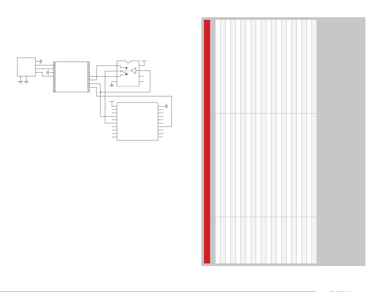
Serial Interface Connections
USB Type B
The serial interface on the MT Series can be connected to any device
capable of serial communication, including microcontrollers, RS-232 drivers
and computers. Figure 17 gives an example of connecting the MT to the
Linx QS Series USB module for connection to a computer.
Connector
GSHD
6
5
GND
DAT+
DAT -
GSHD
4
GND
3
1
2
1
5V
USBDP
2
USBDM
3
GND DSR
4
VCC
5
SUSP_IND
6
RX_IND
TX_IND
7
485_TX
89
SDM-USB-QS
DCD
DATA_IN
DATA_OUT
RTS
CTS
DTR
RI
16
15
14
13
12
11
10
1
2
3
4
GND
MAX4544
VCC
1
VCC
2
D6
3
D7
4
CRT/LRN
5
ENC_SEL
6
SER_IO
7
CONFIRM
8
TR_PDN
9
TR_SEL
10 11
TR_DATA
VCC
8
V+
7
6
NC
5
NC
SEL_BAUD
MODE_IND
LICAL-TRC-MT
GND
LATCH
20
19
D5
18
D4
17
D3
16
15
14
13
D2
12
D1
D0
Figure 17: MT Series Transcoder Serial Interface to a PC
The USB module follows the RS-232 convention of using separate lines
for data input and data output while the transcoder has a single line for all
data. This requires a switch to alternatively connect the transcoder’s SER_
IO line to the DATA_IN and DATA_OUT lines on the module.
The RTS line is used to throw the switch as well as to activate the CRT/
LRN line placing the transcoder into Serial Mode. This gives the PC the
ability to control when communication is initiated.
The MODE_IND line goes high when the transcoder is prepared to send
data, so the CTS line on the USB module is used to monitor the MODE_
IND line. This allows the computer to know when to throw the switch and
look for data from the transcoder.
One point of note is that voltage translation may be necessary if the 5V
USB module is used to communicate with a transcoder operating at 3V.
There are many components and methods for implementing level shifting,
so it is up to the designer to determine the best solution for the product.
– – – –
22 23
Definition Command Reply
Read Local Settings 0x00 - 0x01 - 0x00 - 0x00 - 0x00 - 0x00 - 0x00 - 0xFF 0x00 - 0x41 - 0x43 - 0x4B - A1 - A2 - A3 - IOs - 0xFF
Write Local Settings 0x00 - 0x02 - A1 - A2 - A3 - IOs - 0x00 - 0xFF 0x00 - 0x41 - 0x43 - 0x4B - 0xFF
Read Next User ID 0x00 - 0x11 - 0x00 - 0x00 - 0x00 - 0x00 - 0x00 - 0xFF 0x00 - 0x41 - 0x43 - 0x4B - ID - 0xFF
Write Next User ID 0x00 - 0x12 - ID - 0x00 - 0x00 - 0x00 - 0x00 - 0xFF 0x00 - 0x41 - 0x43 - 0x4B - 0xFF
Read Specific User 0x00 - 0x21 - ID - 0x00 - 0x00 - 0x00 - 0x00 - 0xFF 0x00 - 0x41 - 0x43 - 0x4B - A1 - A2 - A3 - CP - 0xFF
Write Specific User 0x00 - 0x22 - A1 - A2 - A3 - CP - ID - 0xFF 0x00 - 0x41 - 0x43 - 0x4B - 0xFF
Read Target Address 0x00 - 0x31 - 0x00 - 0x00 - 0x00 - 0x00 - 0x00 - 0xFF 0x00 - 0x41 - 0x43 - 0x4B - A1 - A2 - A3 - 0xFF
Write Target Address 0x00 - 0x32 - A1 - A2 - A3 - 0x00 - 0x00 - 0xFF 0x00 - 0x41 - 0x43 - 0x4B - 0xFF
Read Custom Data Value 0x00 - 0x41 - 0x00 - 0x00 - 0x00 - 0x00 - 0x00 - 0xFF 0x00 - 0x41 - 0x43 - 0x4B - Data - 0xFF
Write Custom Data Value 0x00 - 0x42 - Data - 0x00 - 0x00 - 0x00 - 0x00 - 0xFF 0x00 - 0x41 - 0x43 - 0x4B - 0xFF
Read Latch Mask Value 0x00 - 0x51 - 0x00 - 0x00 - 0x00 - 0x00 - 0x00 - 0xFF 0x00 - 0x41 - 0x43 - 0x4B - Mask - 0xFF
Write Latch Mask Value 0x00 - 0x52 - Mask - 0x00 - 0x00 - 0x00 - 0x00 - 0xFF 0x00 - 0x41 - 0x43 - 0x4B - 0xFF
Read Status Outputs 0x00 - 0x61 - 0x00 - 0x00 - 0x00 - 0x00 - 0x00 - 0xFF 0x00 - 0x41 - 0x43 - 0x4B - Outputs - 0xFF
Write Status Inputs 0x00 - 0x62 - Status - Packets - 0x00 - 0x00 - 0x00 - 0xFF 0x00 - 0x41 - 0x43 - 0x4B - 0xFF
MT Series Transcoder Serial Interface Engine Command Set
Read Confirmation EN 0x00 - 0x71 - 0x00 - 0x00 - 0x00 - 0x00 - 0x00 - 0xFF 0x00 - 0x41 - 0x43 - 0x4B - VA L - 0xFF
Figure 18: MT Series Transcoder Serial Interface Engine Command Set
Write Confirmation EN 0x00 - 0x72 - VAL - 0x00 - 0x00 - 0x00 - 0x00 - 0xFF 0x00 - 0x41 - 0x43 - 0x4B - 0xFF
Read Device Targeting EN 0x00 - 0x81 - 0x00 - 0x00 - 0x00 - 0x00 - 0x00 - 0xFF 0x00 - 0x41 - 0x43 - 0x4B - VAL - 0xFF
Write Device Targeting EN 0x00 - 0x82 - VAL - 0x00 - 0x00 - 0x00 - 0x00 - 0xFF 0x00 - 0x41 - 0x43 - 0x4B - 0xFF
Read Custom Data EN 0x00 - 0x91 - 0x00 - 0x00 - 0x00 - 0x00 - 0x00 - 0xFF 0x00 - 0x41 - 0x43 - 0x4B - VAL - 0xFF
Write Custom Data EN 0x00 - 0x92 - VAL - 0x00 - 0x00 - 0x00 - 0x00 - 0xFF 0x00 - 0x41 - 0x43 - 0x4B - 0xFF
A1, A2, A3 = 8-bit values totaling 24-bit address
IOs = Status line input/output settings (0 = output, 1 = input; line D0 corresponds to bit b0)
ID = User ID value (decimal notation, 1 to 60)
CP = Control permissions for the learned transcoder (0 = not authorized, 1 = authorized; line D0 corresponds to bit b0)
Data = value of the custom data byte transferred when the option is enabled
Mask = value used to define which outputs are latched when Latch Mode is enabled (0 = momentary, 1 = latched; line D0 corresponds to bit b0)
Outputs = Current state of the status line outputs (0 = low, 1 = high; line D0 corresponds to bit b0)
Packets = Number of packets to be sent
VAL = Option enable value (0x00 = Off, 0x01 = On)
To delete a specific user, perform a Write Specific User operation with A1, A2, A3, and IOs set to 0xFF
Page 15
Cycle (%)
TX Data Duty
Time (ms)
Max Activation
Time (ms)
Min Activation
(ms)
Packet Time
Max Total
Min Total
Finish
Transmit
Reply
Time
Time
Process
Reply
Wait
(bps)
Baud Rate
Device
Targeted
Addressing
Transmission
Off Off Off 9,600 20.0 9.6 337.6 22.0
Off Off Off 28,800 11.3 5.0 170.0 18.6
On Off Off 9,600 23.0 9.6 337.6 19.1
Confirmation Custom Data
MT Series Transcoder Activation Times and Transmitted Packet Duty Cycle
Figure 19: MT Series Transcoder Activation Times and Transmitted Packet Duty Cycle
On Off Off 28,800 11.0 5.0 170.0 19.1
Off On Off 9,600 21.3 11.0 339.0 23.2
Off On Off 28,800 11.9 5.7 170.7 19.3
Off Off On 9,600 23.8 13.8 341.8 25.6
On On Off 28,800 11.6 5.7 170.7 19.8
Off Off On 28,800 12.9 7.0 172.0 20.9
On Off On 9,600 27.2 13.8 341.8 22.4
On Off On 28,800 12.9 7.0 172.0 20.9
On On Off 9,600 24.4 11.0 339.0 20.3
– – – –
24 25
Off On On 9,600 25 15.1 343.1 26.6
Off On On 28,800 13.4 7.6 172.6 21.6
On On On 9,600 28.6 15.1 343.1 23.3
On On On 28,800 13.6 7.6 172.6 21.3
Cmd
Process
Cmd
Receive
Max
Ready
0.08 33.00 8.30 1.07 4.00 5.29 870.00 890.00 925.00
Restore Default
(9,600bps)
0.08 17.00 2.80 1.07 4.00 1.73 870.00 880.00 900.00
Restore Default
(28,800bps)
Figure 21: MT Series Transcoder Serial Interface Engine Timings (ms)
Ready
SER_IO = Input SER_IO = Output
Minimum Activation time without Transceiver Power Control
Maximum Activation time with Transceiver Power Control
MT Series Transcoder Restore Default Serial Interface Engine Command
Definition Command Reply
Restore Default 0x00 - 0xFF - 0x52 - 0x73 - 0x74 - 0x4D - 0x54 - 0xFF 0x00 - 0x41 - 0x43 - 0x4B - 0xFF
Figure 20: MT SeriesTranscoder Restore Default Serial Interface Engine Command
MT Series Transcoder Serial Interface Engine Timings (ms)
Definition Min
Page 16

Transcoder MODE_IND Denitions
The MODE_IND line is the primary means of indicating the state of the
transcoder to the user. The table below gives the definitions of the
MODE_IND signals.
MT Series Transcoder MODE_IND Definitions
MODE_IND Signals Description
Receive Mode
Create Address Mode
Learn Mode
Erase Mode
Serial Interface Mode
*Blink = ON for 1sec and OFF 250ms
*Flash = ON for 65ms and OFF for 65ms
Figure 22: MT Series Transcoder MODE_IND Definitions
ON for as long as the transcoder is receiving data from a
learned user. This only indicates authorized data reception, not
status output activation.
ON during address generation while the CRT/LRN line is HIGH,
then it flashes* when the CRT/LRN line is taken LOW. Once the
15-second timer expires or the CRT/LRN line is asserted again,
the MODE_IND line turns OFF.
ON while the CRT/LRN line is held HIGH until taken LOW to
enter Learn Mode, then it flashes* for 15 seconds until the timer
expires or the CRT/LRN line is asserted again. If the 60th user
profile has been saved, it blinks* 5 times to indicate the next
user profile will overwrite the first.
ON while the CRT/LRN line is held HIGH for 10 seconds and
Erase Mode is entered, then it turns OFF until the CRT/LRN
line is released. It then turns back ON again for 2 seconds to
indicate erase completion.
OFF while a command is being received (SER_IO = input) and
ON while an ACK/reply is being sent (SER_IO = output).
Legal Considerations
If the transcoder is to be used with a transceiver operating in the 260MHz
to 470MHz ISM band in the United States under Part 15.231, then there
are some legal requirements that need to be considered. The FCC requires
that the transmission control something, so the transcoder cannot be
used simply for passing data. The data lines and CONFIRM line must be
connected to something that turns on or off, such as a motor, LED, buzzer,
or display. Application Note AN-00128 goes into this in detail.
The transcoder has the ability to be automatically activated with the Write
Status Inputs command through the SIE. The FCC requires that any
automatic transmission cease within 5 seconds of activation. The MT
could exceed this time depending on the baud rate used, the options that
are enabled, and the number of packets that are sent. Figure 19 shows
the packet time at each baud rate with the various options enabled or
disabled. The designer needs to be aware of the time depending on the
options that are in use and adjust the packet counter in the command to
ensure that the total time does not exceed 5 seconds. Application Note
AN-00157 goes into the serial commands in more detail and Application
Note AN-00125 goes into the FCC regulations under Part 15.231.
Helpful Application Notes From Linx
It is not the intention of this manual to address in depth many of the issues
that should be considered to ensure that the modules function correctly
and deliver the maximum possible performance. As you proceed with your
design, you may wish to obtain one or more of the following application
notes which address in depth key areas of RF design and application of
Linx products. These application notes are available online at
www.linxtechnologies.com or by contacting Linx.
Helpful Application Note Titles
Note Number Note Title
AN-00100 RF 101: Information for the RF Challenged
AN-00125 Considerations for Operation Within the 260–470MHz Band
AN-00128 Data and Bidirectional Transmissions under Part 15.231
AN-00157 Connecting to the Serial Interface on the MT Series Transcoders
AN-00310 Encoder and Decoder Comparison
AN-00320 The Basics of Remote Control and Remote Keyless Entry
Figure 23: Helpful Application Note Titles
– – – –
26 27
Page 17
Typical Applications
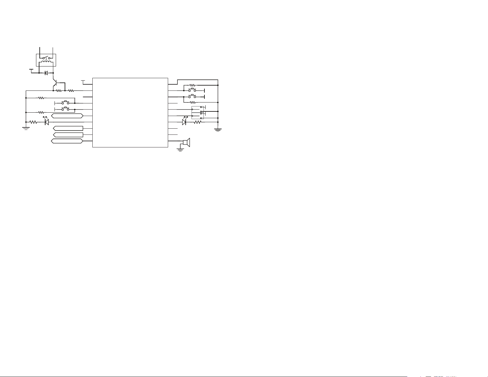
The MT Series transcoder is ideal for replicating button presses for remote
control applications. An example application circuit is shown in Figure 24.
VCC
VCC
100k
100k
VCC
VCC
To Processor or PC
To Transceiver
2.2k10k
To Transceiver
To Transceiver
1
2
3
4
5
6
7
8
9
10 11
LICAL-TRC-MT
VCC
D6
D7
CRT/LRN
ENC_SEL
SER_IO
CONFIRM
TR_PDN
TR_SEL
TR_DATA
LATCH
SEL_BAUD
MODE_IND
GND
D5
D4
D3
D2
D1
D0
20
19
18
17
16
15
14
13
12
100k
VCC
VCC
100k
VCC
VCC
Data Lines D0 through D7 can be individually set up as either inputs or
outputs. In this example, D4 and D5 have buttons connected to them,
so they are set up as inputs, and D0 and D6 are set up as outputs. D0
is connected directly to a piezoelectric buzzer. Line D6 activates a relay
through a transistor buffer when it goes high. A buffer like this may be
needed if the load requires more than 25mA of current or a higher voltage
source to activate. The transcoder turns on the transistor, which can be
selected to provide the appropriate drive levels to activate the relay.
Operation with the MS Series
The MT Series transcoders are fully compatible with the MS Series
encoders and decoders. Tying the ENC_SEL line high makes the
transcoder operate just like an MS Series encoder. Tying this line low
enables it to become an MS decoder or a transcoder, depending on how it
is set-up. This is described in detail in the Transcoder Operation section.
Figure 24: MT Series Transcoder Application Circuit
SPDT switches are used to select the baud rate and set the latch mode.
These can be tied directly to supply or ground if they will not change.
The TR_PDN line can be connected to the PDN line of a transceiver or it
can be left floating.
SER_IO can be connected to a microprocessor or a PC to program the
transcoder through the serial command set or to record the transmitter
identity. Application Note AN-00157 has sample code.
An LED indicator is attached to the MODE_IND line to provide visual
feedback to the user that an operation is taking place. This line can
source a maximum of 25mA, so the limiting resistor may not be needed,
depending on the LED chosen and the brightness desired.
The CONFIRM line is connected to an LED to indicate that the remote
device successfully received the command.
The CRT/LRN and ENC_SEL lines are connected to buttons that pull the
lines high when pressed. 100kΩ resistors are used to pull the lines to
ground when the buttons are released.
There are two important issues of note when using the transcoders with
the MS Series. First, only two of the MS baud rates are supported by the
MT; 9,600bps and 28,800bps. Second, the MS Series does not respond to
the advanced features of the MT, like the custom data and Targeted Device
Addressing. The main advantage offered by the MT over the MS is the
serial interface. This allows a number of advanced options to be realized.
Some other advantages are:
• More users (60 vs. 40)
• Automatic confirmation
• The lower duty cycles (25% vs. 50%) of the MT Series allows for greater
range in countries like the United States that average transmitter output
power over time
• The serial output on every packet instead of just once per receive
session
• Allows existing receive stations using the MS Series decoder to be
upgraded to take advantage of the advanced features without having to
upgrade existing transmitter stations based on the MS Series encoder
• Mixed MS / MT-based systems that allow cost savings for units that only
require unidirectional operation while other units require bidirectional
operation
The TR_DATA line is connected directly to the data line of the transceiver.
– – – –
28 29
Page 18

Design Steps to Using the MT Series
Communicate through the serial interface
Creation of an Address and assignment of status lines
1. Take the CRT/LRN line high while the ENC_SEL line is high to enter
Create Mode.
2. The Address is randomized for as long as the CRT/LRN line is high
(the ENC_SEL is not monitored once Create Mode has been entered).
The MODE_IND line goes high to indicate that the Address is being
randomized.
3. Release the CRT/LRN line and the MODE_IND line begins switching to
indicate that the transcoder is ready to set status line assignments.
4. Take each line that is to be an input high within fifteen seconds.
5. Take the CRT/LRN line high again or let the transcoder time out after
fifteen seconds to exit Create Mode.
Learn another transcoder's Address
1. Take the CRT/LRN line high then low to enter Learn Mode.
2. The MODE_IND line begins switching to indicate that the transcoder is
ready to receive a transmission. On the transmitting side, activate each
status line that is to be authorized. The transcoder records the Address
and the activated status lines as the Control Permissions.
3. Take the CRT/LRN line high again or let the transcoder time out after
fifteen seconds to exit Learn Mode.
Erase all Address in memory
1. Take the CRT/LRN line high and hold for ten seconds.
1. Take the CRT/LRN line high while the SER_IO line is high to enter Serial
Mode.
2. Use a microcontroller or serial interface to write the desired serial
command to the transcoder LSB first with 1 start bit, 1 stop bit, and no
parity at the baud rate determined by the SEL_BAUD line.
3. Read the acknowledgement and response (if there is one) from the
transcoder LSB first with 1 start bit, 1 stop bit, and no parity at the
baud rate determined by the SEL_BAUD line.
Open Access Mode
The MT Series has the option of accepting all valid transmissions,
regardless of address. This allows the designer to set up an external
database for learned users and control permissions. These external parts
can be used with the transcoder to give the end product more memory
to increase the number of users and more processing speed have a
faster response time when scanning through the user list. In this mode,
the transcoders become a data pipe around which a designer can create
a larger, more complicated system than can be implemented with the
transcoders alone.
The access can be locked simply by learning a user. From this point on, it
returns to normal operation and requires that the transmission have a valid,
learned address before it responds.
The Restore Default command sent on the serial interface places the
transcoder Open Access Mode. This command removes all existing
settings and restores the transcoder to the factory default condition. This
also enables a default address.
2. The MODE_IND line goes high when the CRT/LRN line is activated,
then low after ten seconds to indicate that the memory has been
erased.
– – – –
30 31
Warning: Care must be taken when using the open access
!
mode. Any valid MT or MS transmission activates the transcoder and
is output, regardless of whether or not it is from the intended system.
Additional validation steps must be implemented to prevent unintended
activation.
Page 19
Power Up
Initialize and pull
all outputs low
Set the ON timer
time to 10%
Config
Mode
Is the
No
ENC_SEL line
high?
Yes
Set as encoder
Has an
created?
Is the
ENC_SEL
line high?
Is the
line high?
Mode
Select
line low
Sleep
lines high?
Is the
high?
Yes
No
YesNo
All status lines
are inputs
Set the baud rate
to 9,600bps
No
Yes
Yes
Go to
Transmit
No
Mode
Yes
Go to
Config.
No
Mode
All status lines
are outputs
Set the baud rate
to 28,800bps
address been
Set status lines
according to
assignments
Yes No
SEL_BAUD
Encoder only?
Pull the TR_PDN
Are any status
CRT/LRN line
Figure 25: MT Series Transcoder Power-up Flowchart
Pull the TR_PDN
Line High
Are any status
lines high?
CRT/LRN line
TR_DATA line
No
ON timer
timeout?
Pull the TR_PDN
Line Low
Set the OFF timer
Stop the OFF
Is the
high?
Is the
high?
to 90%
Sleep
Timer
Is the
Is the
high?
Go to
Mode
Select
Yes
No
No
Yes
Yes
Yes
No
Yes
Yes
Did the
Timeout timer
timeout?
No
Is the
CRT/LRN line
high?
No
Any valid data?
Yes
Update the Control
Permissions
Is Confirm
enabled?
Yes
Send the
confirmation packet
Save new Address
and Control
Permissions
Go to
Mode
Select
Get incoming
serial data
Randomize the
address
CRT/LRN line
Write the new
address to memory
Did the
Yes
Timeout timer
timeout?
Is the
high?
Was a valid
command
received?
Process command
Yes
No
operation
Send reply
message
Select
Go to
Mode
No
Yes
No
Get and update the
status line
assignments
No
Is the
CRT/LRN line
high?
No
Yes
Save new status
line assignment
value to memory
Set status lines
according to the
No
assignments
Go to
Mode
Select
Is the SER_IO
line high?
Yes
No
Yes
Go to
Config.
No
Mode
Yes
Go to
Receive
No
Mode
Yes
Transmit
Set to Transmit
Assemble the
Send the packet
Set to Receive
Confirm Wait
timer timeout?
Any valid
No
confirmation
Pull the CONFIRM
line high
Set to Transmit
Are any status
lines high?
Confirm Bounce
timer timeout?
Pull the CONFIRM
Mode
Mode
packet
Mode
Did the
data?
Mode
Did the
line low
Yes
No
Yes
No
Go to
Mode
Yes
Select
No
Yes
Start Erase timer
CRT/LRN line
No
Did the Erase
timer timeout?
Erase memory
ENC_SEL
line high?
Figure 26: MT Series Transcoder Configure Flowchart
– – – –
32 33
Page 20

Go to
Mode
Select
Yes
No
Receive
Mode
Did the
RX Mode
timer timeout?
No
Any valid data?
Yes
Was the
received packet
targeted?
Yes
Does the
target address
match the local
address?
Yes
Recommended Pad Layout
The MT Series transcoders are implemented in an industry standard
20-pin Shrink Small Outline Package (20-SSOP). The recommended layout
dimensions are shown in Figure 5.
0.047
(1.19)
No
Is Confirm
No
No
enabled?
Yes
Assemble the
confirmation packet
Send the
confirmation packet
Set to
Receive Mode
Reset RX
Mode timer
Figure 28: PCB Layout Dimensions
0.016
(0.41)
0.026
(0.65)
0.234 (5.94)
0.328 (8.33)
Is Confirm
enabled?
Set to
Transmit Mode
AND the Command
Byte with Output
Mask creating
Output Byte
Are any bits
in the Output
Byte high?
No
Is the LATCH
line high?
XOR Output Byte
with current status
line output states
Output the Output
Byte on the status
Output TXID,
received Data byte,
and CstmData byte
on the SER_IO line
lines
No
Production Considerations
These surface-mount components are designed to comply with standard
Yes
reflow production methods. The recommended reflow profile is shown
below and should not be exceeded, as permanent damage to the part may
result.
Lead-Free
275
250
No
Yes
Yes
225
200
175
150
125
100
75
TEMPERATURE (°C)
50
25
Figure 29: MT Series Reflow Profile
Sn / Pb
260°C Max
240°C Max
0
020406080 100 120 140 160 180 200 220 240 260 280 300 320
TIME (SECONDS)
340 360 380 420400
Figure 27: MT Series Transcoder Receive Flowchart
– – – –
34 35
Page 21

Linx Technologies
159 Ort Lane
Merlin, OR, US 97532
Phone: +1 541 471 6256
Fax: +1 541 471 6251
www.linxtechnologies.com
Disclaimer
Linx Technologies is continually striving to improve the quality and function of its products. For this reason, we
reserve the right to make changes to our products without notice. The information contained in this Data Guide
is believed to be accurate as of the time of publication. Specifications are based on representative lot samples.
Values may vary from lot-to-lot and are not guaranteed. “Typical” parameters can and do vary over lots and
application. Linx Technologies makes no guarantee, warranty, or representation regarding the suitability of any
product for use in any specific application. It is the customer’s responsibility to verify the suitability of the part for
the intended application. NO LINX PRODUCT IS INTENDED FOR USE IN ANY APPLICATION WHERE THE SAFETY
OF LIFE OR PROPERTY IS AT RISK.
Linx Technologies DISCLAIMS ALL WARRANTIES OF MERCHANTABILITY AND FITNESS FOR A PARTICULAR
PURPOSE. IN NO EVENT SHALL LINX TECHNOLOGIES BE LIABLE FOR ANY OF CUSTOMER’S INCIDENTAL OR
CONSEQUENTIAL DAMAGES ARISING IN ANY WAY FROM ANY DEFECTIVE OR NON-CONFORMING PRODUCTS
OR FOR ANY OTHER BREACH OF CONTRACT BY LINX TECHNOLOGIES. The limitations on Linx Technologies’
liability are applicable to any and all claims or theories of recovery asserted by Customer, including, without
limitation, breach of contract, breach of warranty, strict liability, or negligence. Customer assumes all liability
(including, without limitation, liability for injury to person or property, economic loss, or business interruption) for
all claims, including claims from third parties, arising from the use of the Products. The Customer will indemnify,
defend, protect, and hold harmless Linx Technologies and its officers, employees, subsidiaries, affiliates,
distributors, and representatives from and against all claims, damages, actions, suits, proceedings, demands,
assessments, adjustments, costs, and expenses incurred by Linx Technologies as a result of or arising from any
Products sold by Linx Technologies to Customer. Under no conditions will Linx Technologies be responsible for
losses arising from the use or failure of the device in any application, other than the repair, replacement, or refund
limited to the original product purchase price. Devices described in this publication may contain proprietary,
patented, or copyrighted techniques, components, or materials. Under no circumstances shall any user be
conveyed any license or right to the use or ownership of such items.
©2015 Linx Technologies. All rights reserved.
The stylized Linx logo, Wireless Made Simple, WiSE, CipherLinx and the stylized CL logo are trademarks of Linx Technologies.
 Loading...