

Page 1

MS Series
Remote Control Decoder
Data Guide
Page 2

Warning: Some customers may want Linx radio frequency (“RF”)
!
products to control machinery or devices remotely, including machinery
or devices that can cause death, bodily injuries, and/or property
damage if improperly or inadvertently triggered, particularly in industrial
settings or other applications implicating life-safety concerns (“Life and
Property Safety Situations”).
Table of Contents
1 Description
1 Features
1 Applications
NO OEM LINX REMOTE CONTROL OR FUNCTION MODULE
SHOULD EVER BE USED IN LIFE AND PROPERTY SAFETY
SITUATIONS. No OEM Linx Remote Control or Function Module
should be modified for Life and Property Safety Situations. Such
modification cannot provide sufficient safety and will void the product’s
regulatory certification and warranty.
Customers may use our (non-Function) Modules, Antenna and
Connectors as part of other systems in Life Safety Situations, but
only with necessary and industry appropriate redundancies and
in compliance with applicable safety standards, including without
limitation, ANSI and NFPA standards. It is solely the responsibility of any
Linx customer who uses one or more of these products to incorporate
appropriate redundancies and safety standards for the Life and
Property Safety Situation application.
Do not use this or any Linx product to trigger an action directly
from the data line or RSSI lines without a protocol or encoder/
decoder to validate the data. Without validation, any signal from
another unrelated transmitter in the environment received by the module
could inadvertently trigger the action.
All RF products are susceptible to RF interference that can prevent
communication. RF products without frequency agility or hopping
implemented are more subject to interference. This module does not
have a frequency hopping protocol built in.
2 Ordering Information
2 Absolute Maximum Ratings
2 Timings
3 Electrical Specications
4 Pin Assignments
6 Design Considerations
7 A Practical Example
8 Baud Rate Selection
9 Decoder Operation
9 Receive Mode
9 Learn Mode
10 Latch Mode
10 Receiver Control Mode
11 TX ID
11 System Example
12 Typical Applications
15 Recommended Pad Layout
15 Production Considerations
Do not use any Linx product over the limits in this data guide.
Excessive voltage or extended operation at the maximum voltage could
cause product failure. Exceeding the reflow temperature profile could
cause product failure which is not immediately evident.
Do not make any physical or electrical modifications to any Linx
product. This will void the warranty and regulatory and UL certifications
and may cause product failure which is not immediately evident.
Page 3

MS Series Remote Control Decoder
0.309
Data Guide
Description
MS Series encoders and decoders are designed
for remote control applications. They allow the
status of up to eight buttons or contacts to be
0.026
(0.65)
securely transferred via a wireless link. The large
twenty-four bit address size makes transmissions
highly unique, minimizing the possibility of
0.013
(0.32)
multiple devices having conflicting addresses.
The MS Series decoder allows the recognition
of individual output lines to be easily defined
for each transmitter by the manufacturer or the
end user. This enables the creation of unique
0.007
(0.18)
user groups and relationships. The decoder also
identifies and outputs the originating encoder
Figure 1: Package Dimensions
ID for logging or identification. Housed in a tiny
20-pin SSOP package, MS Series encoders feature low supply voltage and
current consumption. Selectable baud rates and latched or momentary
outputs make the MS Series truly versatile.
(7.85)
0.207 (5.25)
LICAL-DEC-MS001
YYWWNNN
0.030
(0.75)
0.284
(7.20)
0.002
(0.05)
0.079
(2.00)
Features
• Secure 224 possible addresses
• 8 data lines
• Direct serial interface
• Latched or momentary outputs
• Definable recognition authority
• Encoder ID output by decoder
• Low 2.0 to 5.5V operating
voltage
Applications
• Keyless entry
• Door and gate openers
• Security systems
• Remote device control
• Low supply current (370µA @ 3V)
• Ultra-low 0.1µA standby current
• True serial encoding
• Excellent noise immunity
• Selectable baud rates
• No programming required
• Small SMD package
• Car alarms / starters
• Home / industrial automation
• Remote status monitoring
• Lighting control
– –
1
Revised 3/18/2015
Page 4
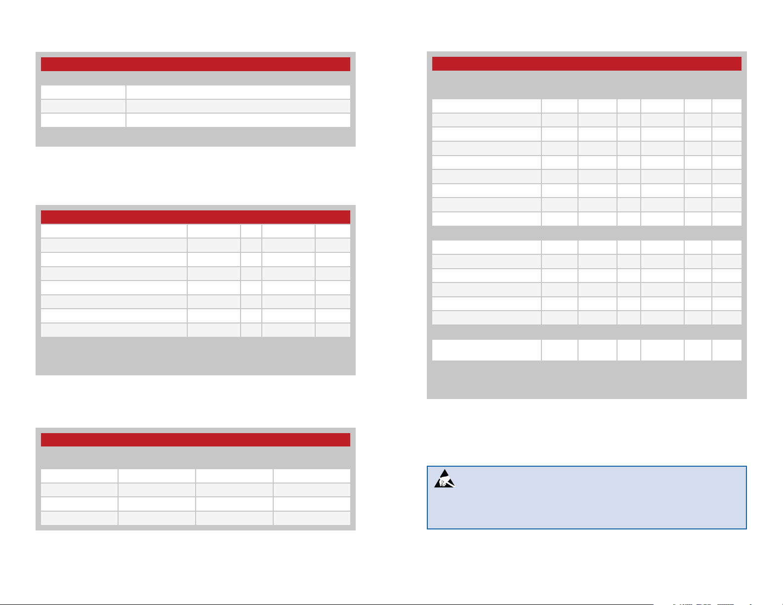
Electrical SpecicationsOrdering Information
Ordering Information
Part Number Description
LICAL-ENC-MS001 MS Encoder
LICAL-DEC-MS001 MS Decoder
MDEV-LICAL-MS MS Master Development System
MS decoders are shipped in reels of 1,600
Figure 2: Ordering Information
Absolute Maximum Ratings
Absolute Maximum Ratings
Supply Voltage V
CC
Any Input or Output Pin −0.3 to V
Max. Current Sourced by Output Pins 25 mA
Max. Current Sunk by Input Pins 25 mA
Max. Current Into V
CC
Max. Current Out Of GND 300 mA
Operating Temperature −40 to +85 ºC
Storage Temperature −65 to +150 ºC
Exceeding any of the limits of this section may lead to permanent damage to the device.
Furthermore, extended operation at these maximum ratings may reduce the life of this
device.
Figure 3: Absolute Maximum Ratings
−0.3 to +6.5 VDC
+ 0.3 VDC
CC
250 mA
MS Series Deccoder Specifications
Parameter Symbol Min. Typ. Max. Units Notes
Power Supply
Operating Voltage V
Supply Current l
At 2.0V V
At 3.0V V
At 5.0V V
CC
CC
CC
Power Down Current l
At 2.0V V
At 3.0V V
At 5.0V V
CC
CC
CC
CC
CC
PDN
2.0 5.5 VDC
240 300 µA 1
370 470 µA 1
670 780 µA 1
0.10 0.80 µA
0.10 0.85 µA
0.20 0.95 µA
Decoder Section
Input Low V
Input High V
Output Low V
Output High V
IL
IH
OL
OH
0.0 0.15 x V
0.8 x V
CC
CC
V
CC
0.6 V
VCC – 0.7 V
V 2
V 3
Input Sink Current 25 mA
Output Drive Current 25 mA
Environmental
Operating Temperature
Range
–40 +85 °C
1. Current consumption with no active loads.
2. For 3V supply, (0.15 x 3.0) = 0.45V max.
3. For 3V supply, (0.8 x 3.0) = 2.4V min.
Timings
Encoder SEND to Decoder Activation Times (ms)
Baud Rate Initial Start-Up After Valid Rx
2,400 72.62 38.62 600 + 72.62
9,600 22.42 12.42 300 + 22.42
19,200 13.80 7.30 150 + 13.80
28,800 11.00 6.00 150 + 11.00
Figure 4: Encoder SEND to Decoder Activation Times (ms)
– – – –
2 3
Figure 5: Electrical Specifications
With RX_PDN
(Worst Case)
Warning: This product incorporates numerous static-sensitive
components. Always wear an ESD wrist strap and observe proper ESD
handling procedures when working with this device. Failure to observe
this precaution may result in module damage or failure.
Page 5
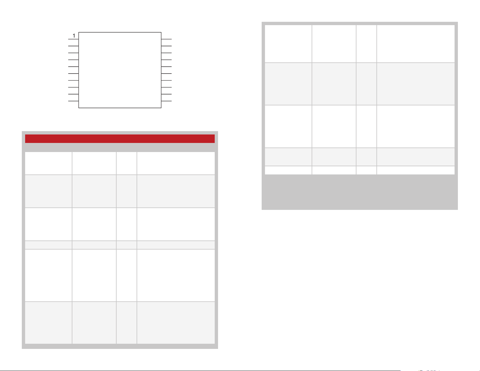
Pin Assignments
6
0
1
D
D
CH
L
D
D
5
3
CC
CC
0
N
0
3
5
6
8
9
0
LICAL-DEC-MS001
D
SEL_BAUD
SEL_BAUD
N
N
LAT
RX_CNT
TX_I
1
MODE_IN
Figure 6: MS Series Deccoder Pin Assignments
Pin Descriptions
Pin Number Name I/O Description
1, 2, 13, 14, 17–20 DO–D7 O
3 SEL_BAUD0 I
4 SEL_BAUD1 I
5, 6 GND Ground
7 LATCH I
8 RX_CNTL I/O
2
D
1
1
D
1
V
1
V
1
D
DATA_I
Data Output Lines. These
lines reproduce the state of
the encoder's data lines upon
reception of a valid packet.
Baud Rate Selection Line 0. This
line along with SEL_BAUD1 sets
the baud rate of the serial data
stream to one of 4 possible rates.
The rate must be set before power
on.
Baud Rate Selection Line 1. This
line along with SEL_BAUD0 sets
the baud rate of the serial data
stream to one of 4 possible rates.
The rate must be set before power
on.
Set Latched Outputs. If this line
is low, then the data outputs are
momentary (active for as long
as a valid signal is received). If
this line is high, the outputs are
latched (when a signal is received
to make a particular data line
high, it remains high until another
transmission is received instructing
it to go low).
External Receiver Control
Line. This line can be used to
automatically power on and off
a receiver. It powers the receiver
down for ten times as long as
it is powered on. The times are
determined by the selected baud
rate.
Transmitter ID Output Line.
A unique ID number for each
9 TX_ID O
10 MODE_IND O
11 LEARN I
12 DATA_IN I
15, 16 V
None of the input lines have internal pull-up or pull-down resistors. The input lines must
always be in a known state (either GND or VCC) at all times or the operation may not
be predictable. The designer must ensure that the input lines are never floating, either
by using external resistors, by tying the lines directly to GND or VCC, or by use of other
circuits to control the line state.
Figure 7: Pin Descriptions
CC
transmitter is stored in the
decoder’s memory. A byte is
output as serial data on this line
to indicate which transmitter a
transmission came from.
Mode Indicator Output. This line
switches when a valid transmission
is received, when Learn Mode is
entered, and when the memory
is cleared. This allows for the
connection of a LED to indicate
to the user that these events have
taken place.
Learn Mode Activation Line. When
this line goes high, the decoder
enters Learn Mode to accept an
Address from an encoder and
store it in memory. If it is held high
for ten seconds, the decoder
clears all stored Addresses from
memory.
Data Input Line. This line accepts
the encoded serial data stream
from a receiver.
Supply Voltage
– – – –
4 5
Page 6

Design Considerations
The Linx MS Series encoders and decoders are designed for remote
control applications. They provide an easy way to securely register button
presses or switch closures over a wireless link. The encoder side turns the
status of eight parallel input lines into a secure, encoded, serial bit-stream
output intended for transmission via an RF or infrared link. Once received,
the decoder decodes, error checks, and analyzes the transmission. If the
transmission is authenticated, the output lines are set to replicate the status
of the lines on the encoder.
Prior to the arrival of the Linx MS Series, encoders and decoders typically
fell into one of two categories. First were older generation, low-security
devices that transmitted a fixed address code, usually set manually with a
DIP switch. These address lines frequently caused the user confusion when
trying to match a transmitter to a receiver. Another disadvantage was the
possibility that address information could be captured and later used to
compromise the system.
These concerns resulted in the development of a second type of encoder
/ decoder that focused on security and utilized encryption to guard
against code cracking or code grabbing. Typically, the encoding of each
transmission changes based on complex mathematical algorithms to
prevent someone from replicating a transmission. These devices gained
rapid popularity due to their high security and the elimination of manual
switches; however, they imposed some limitations of their own. Such
devices typically offer a limited number of inputs, the transmitter and
receiver can become desynchronized, and creating relationships and
associations between groups of transmitters and receivers is difficult.
The Linx product line, which includes the MS and HS Series, is the first
product line to offer the best of all worlds. Both series accept up to eight
inputs, allowing a large number of buttons or contacts to be connected.
The devices also allow relationships among multiple encoders and
decoders to be easily created. Security is well provided for. The MS Series
uses a random fixed word with 224 possible combinations to give a high
level of uniqueness and a reasonable level of security. For applications
requiring the highest security, the HS Series, which employs tri-level,
maximum-security encryption, should be considered.
by many competitive devices. This allows products based on MS or HS
devices to achieve superior range and immunity from interference, edge
jitter, and other adverse external influences.
One of the most important features unique to the MS and HS products
is their ability to establish a unique user identity and profile for the device
containing the encoder. In conventional designs, all encoded transmissions
are either recognized or denied based on the address. In cases where
encoder and decoder addresses match, the state of all data lines is
recognized and output. Linx products uniquely allow a user or manufacturer
to define which encoder inputs are acknowledged by each decoder. MS
series decoders can store up to 40 system users and unique profiles for
each. This allows for an incredible variety of unique relationships among
multiple system components and opens the door to product features not
previously possible.
A Practical Example
Consider this practical example: a three door garage houses Dad’s
Corvette, Mom’s Mercedes and Son’s Yugo. With most competitive
products, any user’s keyfob could open any garage door as long as the
addresses match. In a Linx MS-based system, the keyfobs could easily
be configured to open only certain doors (guess which one Son gets to
open!) The MS Series also allows for component grouping. Imagine a
remote control designed for use in a woodshop. One button could turn
on a vacuum, one an air cleaner, and another a light, yet another button
could then be user configured to turn on all of them with a single touch.
The MS Series uniquely combines security and simplicity with the power
to create groups and relationships. Figure 8 compares the advantages and
disadvantages of different encoders.
Encoder transmission protocol and methodology is a critical but often
overlooked factor in range and noise immunity. The MS and HS products
utilize a true serial data stream rather than the PWM schemes employed
– – – –
6 7
Page 7
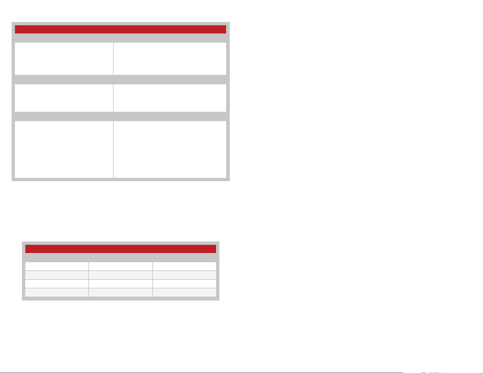
Encoder Comparison Table
Manual Address Encoders
Advantages
High number of button inputs
"Rolling Code" Encoders
Advantages
Highly secure
Eliminates manual address settings
Linx Encoders
Advantages
High number of button inputs
Highly unique (MS)
Highest security available on the market (HS)
Eliminates manual address settings
Allows for associative relationships
Cannot unsynchronize
Serial data output
Encoder ID is output by the decoder
Latched or momentary outputs (MS)
External transmitter and receiver control lines
Disadvantages
Low-security fixed code
Confusing manual addressing
Low number of addresses
PWM data output
High security vulnerabilities
Disadvantages
Low number of button inputs
Encoder and decoder can become unsynchronized
Difficult or impossible to create relationships
Security vulnerabilities
Disadvantages
Slightly higher cost for some basic applications
Security vulnerabilities (MS only)
Decoder Operation
When the decoder first powers up, it sets the baud rate and checks the
state of the RX_CNTL line. If this line is pulled high, then the decoder goes
into Receiver Control Mode. If the line is low, it goes to sleep until a rising
edge (low to high transition) on the DATA_IN line puts it into Receive Mode
or a high signal on the LEARN line puts it into Learn Mode.
Receive Mode
When a rising edge is seen on the DATA_IN line, the decoder enters
Receive Mode. The decoder looks for a valid packet, meaning that there
are no errors and that the received Address matches one that is saved in
memory. If there is a match, then the decoder reproduces the states of
the encoder’s data lines on its own data lines. It also outputs the ID of the
encoder once, on reception of the first valid packet. It then looks for the
next valid data packet. If, at any time, an error or an unknown Address is
detected, the decoder ignores the packet and looks for the next one.
If the timer runs out, then the decoder goes back to sleep. This time
is dependent upon the baud rate selected by the user. It is 131ms for
2,400bps and 9,600bps, and 65ms for 19,200bps and 28,800bps.
Figure 8: Encoder Comparison Table
Baud Rate Selection
SEL_BAUD0 and SEL_BAUD1 are used to select the baud rate of the
serial data stream. The state of the lines allows the selection of one of four
possible baud rates, as shown in Figure 9.
Baud Rate Selection Table
SEL_BAUD1 SEL_BAUD0 Baud Rate (bps)
0 0 2,400
0 1 9,600
1 0 19,200
1 1 28,800
Figure 9: Baud Rate Selection Table
The baud rate must be set before power up. The encoder will not recognize
a change in the baud rate setting after it is on.
– – – –
8 9
Learn Mode
In order for the decoder to accept transmissions from an encoder, it must
first learn the encoder’s Address. This is done by taking the LEARN line
high to place the decoder into Learn Mode. The MODE_IND line starts
switching, allowing for connection of an LED to provide visual indication
that the decoder is ready to accept a new Address. This continues until the
LEARN line goes high again, or until a time-out after 17 seconds.
The decoder looks for a valid transmission from an MS Series encoder. It
can store up to 40 Addresses in its memory. When the 40th encoder is
learned, the decoder flashes the MODE_IND line five times as an indication
that the memory is full. The next address learned overwrites the first
address in memory. The memory retains all of the learned Addresses if
power is removed.
If the LEARN line is held high for ten seconds, then the decoder erases all
of the stored Addresses from memory. The MODE_IND line is high for as
long as the LEARN line is high, but after the ten seconds it goes low. Once
the LEARN line is pulled low again, the MODE_IND line goes high for two
seconds to indicate that the memory has been cleared.
Page 8

Latch Mode
The MS Series decoder has two output options based on the state of the
LATCH line. If it is low, then the data lines are momentary, meaning that
they are only high for as long as a valid signal is received. Once the signal
stops and the decoder times out, the lines are pulled low.
If the LATCH line is high, the decoder pulls a data line high upon reception
of a valid signal and holds it high until the signal is received a second time,
at which point the decoder pulls it low. The decoder must see a break and
time out between valid transmissions before it toggles the outputs. The
minimum required time-out periods are listed in the Receive Mode section.
TX ID
The TX_ID line outputs an eight-bit binary number to identify which learned
encoder sent the transmission. The number is output at the baud rate
set by the SEL_BAUD lines and normally corresponds to the order in
which the decoder learned the encoder, so the first encoder learned gets
number ‘1’, the second gets number ‘2’, and so on. An exception arises
when the memory is full, in which case the first numbers are overwritten as
described in the Learn Mode section. Application Note AN-00156 shows
some example software to read the TX_ID and associate it with a particular
encoder. The C and Visual Basic code is well documented so that it can be
modified for a specific application.
Receiver Control Mode
If the RX_CNTL line is pulled high when the decoder initially powers on,
then the decoder enters Receiver Control Mode. Once in this mode, the
RX_CNTL line becomes an output that can be attached to the PDN or
VCC line of a Linx receiver or a similar input on another receiver. This allows
the decoder to power down the receiver when it is not required, thereby
reducing current consumption and prolonging battery life. The decoder
draws full current in this mode, but an active receiver typically draws much
more than the decoder, so a savings is realized.
The decoder activates the receiver for approximately one packet’s time plus
10ms for the receiver to power up, so the actual “on” time depends on the
baud rate chosen by the user. This time can be calculated in milliseconds
as (60/Baud Rate)(1000) + 10. The “off” time is nine times the “on” time,
resulting in a 10% duty cycle, greatly reducing the receiver’s current
consumption. However, there may be a lag time from when the encoder
activates to when the decoder responds. The decoder enters Receive
Mode when it sees a valid packet, so there would only be a lag for the first
packet. This can be reduced by selecting a higher baud rate.
If this feature is not going to be used, then this pin should be tied to
ground. If it is tied to VCC, then the decoder will create a short when it pulls
the line to ground while trying to power down the receiver. This mode is
appropriate for receivers that have a high internal pull-up resistance, such
as those offered by Linx. If the intended receiver does not have a pull-up,
then a 100kΩ or larger resistor to VCC can be added to the RX_CNTL line to
activate this mode.
System Example
The first step in using the decoder is to set the baud rate and determine
if the outputs should be latched or momentary. Next, the decoder needs
to learn the encoder’s Address. This is done by momentarily pressing the
button connected to the LEARN line. The LED connected to the MODE_
IND line begins to flash to indicate that the decoder is ready to learn a new
Address. One of the buttons on the transmitter is pressed to send a signal
to the decoder. Once this is done, the LEARN button is pressed again to
exit Learn Mode.
Now, when a button is pressed on the encoder, the corresponding line on
the decoder activates. If the LATCH line is high, the data line remains high
until the encoder button is pressed again, telling the decoder to pull the line
low.
To clear the decoder's memory, the LEARN button is pressed and held
for ten seconds until the MODE_IND line goes low. Once the button is
released, the LED lights for two seconds to indicate that the memory has
been cleared.
– – – –
10 11
Page 9
Typical Applications
0
00k
eceiver
6
0
1
D
D
CH
L
D
E
5
3
CC
CC
0
N
0
3
5
6
8
9
0
C
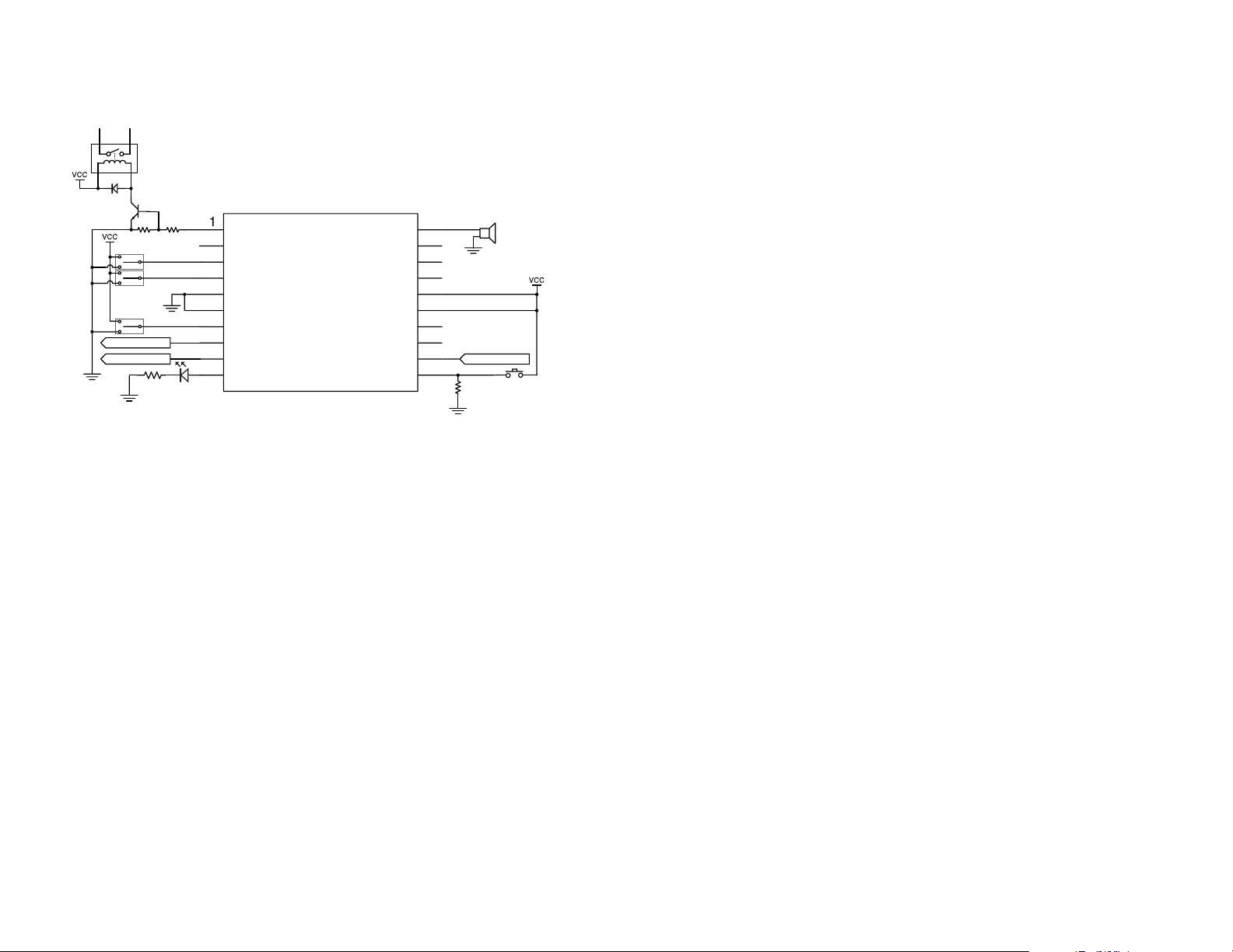
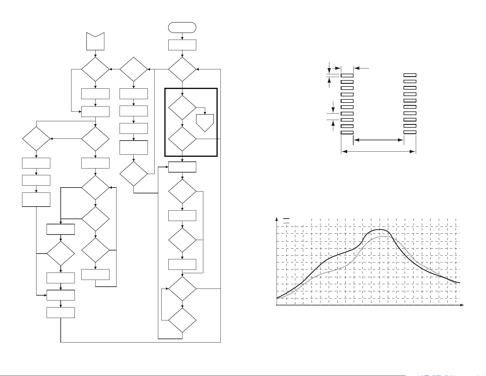
The MS decoder is ideal for replicating button presses for remote control
applications. An example application circuit is shown in Figure 10.
LICAL-DEC-MS001
2.2k
10k
D
SEL_BAUD
SEL_BAUD
N
N
LAT
To Receiver
To Processor or P
22
Figure 10: MS Series Decoder Application Circuit
1
RX_CNT
TX_I
MOD
_IND
DATA_I
SPDT switches are used to select the baud rate and set the latch mode so
that pull-down resistors are not needed.
2
D
1
1
D
1
V
1
V
1
D
From R
1
Data Lines D0 through D7 can be connected directly to the external
circuitry that needs to be activated remotely. In this example, D5 is
connected directly to a piezoelectric buzzer. This causes the buzzer to
sound when the D5 line on the encoder goes high. Line D6 activates a
relay through a transistor buffer when it goes high. A buffer like this may be
needed if the load requires more than 25mA of current or a higher voltage
source to activate. The decoder turns on the transistor, which can be
selected to provide the appropriate drive levels to activate the relay.
The RX_CNTL line can be connected to the PDN line of the receiver or it
can be connected directly to ground.
TX_ID can be connected to a microprocessor or a PC to record the
transmitter identity. Application Note AN-00156 has sample code that
reads the transmitter ID and displays the ID number on a LCD screen.
An LED indicator is attached to the MODE_IND line to provide visual
feedback to the user that an operation is taking place. This line sources a
maximum of 25mA.
The LEARN line is connected to a button that pulls the line high when
pressed. Since the line does not have an internal pull-down resistor, a
100kΩ resistor is used to pull the line to ground when the button is not
pressed.
The DATA_IN line is connected directly to the data output of the receiver.
– – – –
12 13
Page 10
NO
TEMPERATURE (°C)
10 Sec.
Time-Out?
YES
Pull MODE_IND
Line Low
Clear All Memory
Pull MODE_IND
Line High For 2
Sec.
NO
Save New
Address
Is Memory
Full?
YES
Flash MODE_IND
Line 5 Times
Pull MODE_IND
Line Low
Pull RX_CNTL
Line Low
NO
YES
YES
YES
Learn
Mode
Is
RX_CNTL
Used?
YES
Pull RX_CNTL
Line High
Pull MODE_IND
Line High
Is The
LEARN Line
High?
NO
Start Toggling
MODE_IND
Is The
LEARN Line
High?
NO
17 Sec.
Time-Out?
NO
Was Any
Valid Data
Received?
YES
Update Address
YES
NO
Is The
LEARN Line
High?
NO
Pull RX_CNTL
Line Low
Wait 9x "Time On"
(90%)
Pull RX_CNTL
Line High
Wait "Time On"
(1 Packet + 10mS
= 10%)
Did The
DATA_IN Line
Transition?
YES
Power Up
Recommended Pad Layout
The MS Series encoders and decoders are implemented in an industry
Set Baud Rate
standard 20-pin Shrink Small Outline Package (20-SSOP). The
recommended layout dimensions are shown in Figure 12.
0.047
YES
Is
RX_CNTL
Used?
NO
0.016
(0.41)
Sleep
Is The
LEARN Line
High?
Did The
DATA_IN Line
Transition?
NO
Read Data Packet
NO
YES
YES
Go To
Learn
NO
Mode
0.026
(0.65)
Figure 12: PCB Layout Dimensions
(1.19)
0.234 (5.94)
0.328 (8.33)
Production Considerations
NO
Is
The Packet
Valid?
YES
Output Data
First Loop?
YES
Output TX ID
Time Out?
NO
Did The
DATA_IN Line
Transition?
YES
NO
NO
YES
These surface-mount components are designed to comply with standard
reflow production methods. The recommended reflow profile is shown in
Figure 13 and should not be exceeded, as permanent damage to the part
may result.
Lead-Free
275
250
225
200
175
150
125
100
75
50
25
0
Figure 13: MS Series Reflow Profile
Sn / Pb
260°C Max
240°C Max
020406080 100 120 140 160 180 200 220 240 260 280 300 320
TIME (SECONDS)
340 360 380 420400
Figure 11: MS Series Decoder Flowchart
– – – –
14 15
Page 11

Linx Technologies
159 Ort Lane
Merlin, OR, US 97532
Phone: +1 541 471 6256
Fax: +1 541 471 6251
www.linxtechnologies.com
Disclaimer
Linx Technologies is continually striving to improve the quality and function of its products. For this reason, we
reserve the right to make changes to our products without notice. The information contained in this Data Guide
is believed to be accurate as of the time of publication. Specifications are based on representative lot samples.
Values may vary from lot-to-lot and are not guaranteed. “Typical” parameters can and do vary over lots and
application. Linx Technologies makes no guarantee, warranty, or representation regarding the suitability of any
product for use in any specific application. It is the customer’s responsibility to verify the suitability of the part for
the intended application. NO LINX PRODUCT IS INTENDED FOR USE IN ANY APPLICATION WHERE THE SAFETY
OF LIFE OR PROPERTY IS AT RISK.
Linx Technologies DISCLAIMS ALL WARRANTIES OF MERCHANTABILITY AND FITNESS FOR A PARTICULAR
PURPOSE. IN NO EVENT SHALL LINX TECHNOLOGIES BE LIABLE FOR ANY OF CUSTOMER’S INCIDENTAL OR
CONSEQUENTIAL DAMAGES ARISING IN ANY WAY FROM ANY DEFECTIVE OR NON-CONFORMING PRODUCTS
OR FOR ANY OTHER BREACH OF CONTRACT BY LINX TECHNOLOGIES. The limitations on Linx Technologies’
liability are applicable to any and all claims or theories of recovery asserted by Customer, including, without
limitation, breach of contract, breach of warranty, strict liability, or negligence. Customer assumes all liability
(including, without limitation, liability for injury to person or property, economic loss, or business interruption) for
all claims, including claims from third parties, arising from the use of the Products. The Customer will indemnify,
defend, protect, and hold harmless Linx Technologies and its officers, employees, subsidiaries, affiliates,
distributors, and representatives from and against all claims, damages, actions, suits, proceedings, demands,
assessments, adjustments, costs, and expenses incurred by Linx Technologies as a result of or arising from any
Products sold by Linx Technologies to Customer. Under no conditions will Linx Technologies be responsible for
losses arising from the use or failure of the device in any application, other than the repair, replacement, or refund
limited to the original product purchase price. Devices described in this publication may contain proprietary,
patented, or copyrighted techniques, components, or materials. Under no circumstances shall any user be
conveyed any license or right to the use or ownership of such items.
©2015 Linx Technologies. All rights reserved.
The stylized Linx logo, Wireless Made Simple, WiSE, CipherLinx and the stylized CL logo are trademarks of Linx Technologies.
 Loading...