

Page 1
Linx 4900 Ink Jet Printer
Operating Manual
Page 2

Copyright and Disclaimer
Copyright Notice
This publication may not be reproduced, stored in a retrieval system, or
transmitted in whole or in part, in any form or by any means, electronic,
mechanical, photocopying, recording, or otherwise, for any purpose
without the written permission of Linx Printing Technologies plc.
Neither whole nor part of the product described in this operating manual,
may be adapted or reproduced in any material form without prior written
permission of Linx Printing Technologies plc.
This First edition published August 2003
© Linx Printing Technologies plc.
LINX® is the Registered Trademark
of
Linx Printing Technologies plc.
Unauthorized use of the LINX Trademark is strictly forbidden.
Disclaimer
Information of a technical nature, and particulars of the prod uct and its use
are given by Linx in good faith. However, it is acknowledged that there
may be errors or omissions in this operating manual.
Linx shall not be liable for any loss or damage arising from the use of any
information, particulars or errors in this operating manual, or maintenance
carried out by unauthorized personnel, or any incorrect use of the product,
whatsoever.
At all times the printer must be operated with Linx approved spares and
consumables. Maintenance not identified in this operating manual must be
carried out by Linx engineers or its authorized distributors.
MP65492–1 (i) Linx 4900 Operating Manual
Page 3

About this Manual
About this Manual
This manual describes how to operate the Linx 4900 Ink Jet Printer, a
specialist printer system for use in production line environmen ts f or
printing onto a wide range of substrates.
The information contained in this edition of the operating manual is
applicable to software Version 1.0.
Products described in this operating manual are subject to continuous
development, and reviews will be made accordingly in subsequent
editions. Linx will be pleased to receive any correspondence relating to this
operating manual and the information contained herein.
For further information or help with Linx products please contact:
Linx Printing Technologies plc
Burrel Road
St Ives
Cambridgeshire
PE27 3LA
UK
Tel: + 44 (0) 1480 302100
Fax: + 44 (0) 1480 302116
E-mail: [email protected]
or visit our website at www.linx.co.uk.
Equipment Information
This equipment has been tested and found to comply with the limits for a
Class A digital device, pursuant to part 15 of the FCC Rules. These limit s
are designed to provide reasonable protection against harmful interference
when the equipment is operated in a commercial environment. This
equipment generates, uses, and can radiate radio frequency energy and, if
not installed and used in accordance with the instruction manual, may
cause harmful interference to radio communications. Operation of this
equipment in a residential area is likely to cause harmful interference, in
which case the user will be required to correct the interference at his own
expense.
WARNING–EN55022: This is a Class A product. In a domestic
environment this product may cause radio interference, in which case the
user may be required to take adequate measures.
Linx 4900 Operating Manual (ii) MP65492–1
Page 4

Safety
Introduction
This section provides essential information concerning the precautions to
be taken to ensure that all printer operations and routine maintenance are
carried out with the maximum possible safety.
Therefore, it is essential that all operators of a Linx ink jet printer read and
understand this safety section before attempting to operate it or to carry out
any maintenance tasks on it.
About Safety Warnings and Cautions
At appropriate points within the text of this manual safety WARNING and
CAUTION statements are provided. These are designed to draw your
attention to information about the avoidance of hazards and safe handling
of a product. Symbols often accompany these safety statements. NOTES
also provide additional information, however, these are not safety related.
Safety
The different types of safety statements and associated symbols are
defined below along with the conventions used in this operating manual.
Warnings
A WARNING alerts you to the possible hazards which may cause loss of
life, physical injury or illness.
WARNING: THE GENERAL WARNING SYMBOL (SHOWN
TO THE LEFT) ACCOMPANIES A WARNING OF POSSIBLE
HAZARDS, HARMFUL OR POTENTIALLY LETHAL
ACTIVITIES AND THE CONSEQUE NCES OF IGNORING
IT.
WARNING: THE MANDATORY EYE PROTECTION
WARNING SYMBOL INDICATES THAT APPROVED EYE
PROTECTION, WHICH CONFORMS TO EUROPEAN AND
INTERNATIONAL SAFETY STAN DARDS, MUST BE WORN
WHEN CARRYING OUT INK OR SOLVENT RELATED
ACTIVITIES.
WARNING: THE LETHAL VOLTAGE SYMBOL INDICATES
THAT DANGEROUS VOLTAGES ARE PRESENT IN THE
EQUIPMENT WHEN ELECTRICAL POWER IS APPLIED.
THERE IS A DANGER OF DEATH OR INJURY FROM
ELECTRIC SHOCK.
MP65492–1 (iii) Linx 4900 Operating Manual
Page 5

Safety
Cautions
CAUTION: A caution alerts you to activities that may cause damage
to equipment or the environment but are not a direct danger to
personnel.
Notes
NOTE: A Note provides additional information of an advisory nature or
particular interest, but is not safety related.
NOTE: When the hand symbol accompanies a Note, this indicates that
you should take particular notice of the information provided.
Printer Cover Security
The 4900 ink jet printer has a security locking device fitted to the printer
cover, to prevent operators from opening the cover and subjecting
themselves to the potential lethal electrical hazards contained within.
It is essential that operators do not attempt to open the printer cover, for
any reason, whatsoever . No t only is there a danger of fatal or serious injur y ,
but it may also void your Linx warranty.
WA RNING: LETHAL VOLTAGE. DANGEROUS VOLTAGES
ARE PRESENT IN THIS EQUIPMENT WHEN ELECTRICAL
POWER IS APPLIED. THERE IS A DANGER OF DEAT H OR
INJURY FROM ELECTRIC SHOCK.
UNDER NO CIRCUMSTANCES ARE YOU TO ATTEMP T TO
OPEN THE PRINTER COVER OR ATTEMPT TO REMOVE
OR ADJUST A NY COMP ONENTS FITTE D WITHIN THE
PRINTER. ONLY FULLY TRAINED, LINX APPROVED
SERVICE ENGINEERS ARE QUALIFIED TO OPEN THE
PRINTER COVER.
Linx 4900 Operating Manual (iv) MP65492–1
Page 6

Operating the Printer
All personnel operating the printer must be aware of the hazards associated
with ink jet printers. The following safety information should be made
available to all personnel and is applicable to anybody in the printer’s
operating environment.
Only pers onnel who have bee n fully trained and authorized by Linx are
qualified to operate or maintain Linx prin ter s. If you are in any dou bt as t o
your abilities to operate or maintain the printer, DO NOT DO SO; consult
your supervisor for guidance or contact your local Linx distributor who
will be happy to advise you.
• DO NOT smoke or use naked flames in the vicinity o f th e pr inter. The
printer contains flammable inks and solvents
• ALWAYS ensure that the printer electrical supply is isolated prior to
performing cleaning or maintenance activities. Lethal voltages are
present in the printer cabinet and printhead when mains power is
applied, which can cause death or serious injury if the correct
electrical procedures are not observed. When an external alarm is
connected to the printer alarm output, this must be disconnected
before any maintenance activities are carried out.
Never attempt to remove the printer cover. The printer cover
must only be removed by fully trained, Linx approved service
engineers
• AL WAYS check that all cov ers are correctly fitted to the printer befo re
you use it. If you are not sure, ask your supervisor for guidance.
Covers act as safety barriers and also ensure the printer retains its
electromagnetic compatibility
• It is recommended that the printer is situated at least 600 mm from
floor level for your comfort
Safety
MP65492–1 (v) Linx 4900 Operating Manual
Page 7

Safety
Inks and Solvents
The effects of solvents and inks are potentially harmful. Whenever inks
and solvents are used, the following precautions must be observed:
• BEFORE YOU START read the Material Safety Data Sheets. If you
do not fully understand, or are unsure, contact your supervisor for
guidance
If the Material Safety Data Sheets have not been supplied or are not
available, please contact your local Linx distribut or . ALWAYS refer to
the Material Safety Data Sheets before working with inks and solvents
• Ensure that the printing area is adequately ventilated at all times when
working on the printer, or with inks and solvents
• W ear safety eyeglasses that comply with the appropriate European and
International Directives when handling inks and solvents. The eye
protection symbol is shown in this manual, where appropriate, to
remind personnel of the mandatory requirement to WEAR SAFETY
GLASSES
• W ear approved, so lvent resistant gloves. Barrier cream can be applied,
but solvent resistant gloves must be worn when contact with inks or
solvents is likely
• Store all inks and solvents in original containers, tightly closed, in a
well ventilated cabinet away from any source of heat
• Remove all spilt ink and solvent, or build-up of ink deposits
immediately, using the correct solvent type for the ink being used
First Aid
Precautions
Ensure that first aid information is readily available in the event of
ingestion, inhalation, or contact with the skin or eyes.
Ideally, all operators should be trained in First Aid and should be aware of
the effects of working with flammable and toxic substances.
All operators must have access to the ink and solvent Material Safety Data
Sheets, which explain the hazards and medical action to be taken if first aid
is necessary.
Procedures
The following first aid procedures do not supersede any details stated in
the Material Safety Data Sheets, which must be your prime source of first
aid information.
Linx 4900 Operating Manual (vi) MP65492–1
Page 8

Safety
Eye Contact
Contact lenses should be removed. Flush eyes copiously with clean
running water and continue to do so for at least 10 minutes, holding the
eyelids apart.
Obtain medical attention immediately.
Skin Contact
Remove any contaminated clothing. Wash the affected area thoroughly
with soap and water, or use a proprietary skin cleaner. Do NOT use
solvents or thinners to remove ink from skin.
Inhalation
Remove the affected person to fresh air immediately. Keep the affected
person warm and at rest. If breathi ng is irregula r obtain immediate medical
attention.
Ingestion
If accidentally swallowed, obtain immediate medical attention. Wash out
mouth with water and give 200 to 300 ml (half a pint) of water to drink.
Keep at rest. Do NOT induce vomiting; obtain immediate medical
attention.
In Case of Emergency
In an emergency situation you may need to stop the printer quickly. To do
this:
• Switch the printer’ s wall mounted electrical isolator to the off position
to shut off the electricity supply to the printer
• Alternatively, switch the printer mains power supply switch at the rear
of the printer to the ‘0’ (off) position
• Call for medical assistance as required
If possible, the printer should not be left in this state for a long per iod of
time and should be restarted at the earliest possible opportunity to prevent
ink blockages. If there is a hazard that prevents safe access to the printer’s
power supply, do not attempt to shutdown the printer, just vacate the area.
WARNING: IN ALL EMERGENCY CASES, REMOVE THE
CASUALTY FROM THE HAZARD AND CHECK THE
MATERIAL SAFETY DATA SHEETS FOR IMMEDIATE
ACTION. EVACUATE THE CASUAL TY TO MEDICAL AID
IF REQUIRED.
MP65492–1 (vii) Linx 4900 Operating Manual
Page 9

Safety
Noise Emissions
The noise emission level from this printer does not exceed 70 dBA.
This means that there is no hazard to hearing from long-term exp osure and,
therefore, no legal requirement for ear protection to be wo rn when working
in the vicinity of this printer.
Linx 4900 Operating Manual (viii) MP65492–1
Page 10

Contents
Contents
Copyright Notice .............................................................................................................i
Disclaimer.......................................................................................................................i
About this Manual..........................................................................................................ii
Equipment Information...................................................................................................ii
Safety ..................................................................................................................................... iii
Introduction...................................................................................................................iii
About Safety Warnings and Cautions...........................................................................iii
Printer Cover Security...................................................................................................iv
Operating the Printer .....................................................................................................v
Inks and Solvents .........................................................................................................vi
First Aid.........................................................................................................................vi
Noise Emissions......................................................................................................... viii
Using this Manual ................................................................................................................ xv
How this Manual is Organized.....................................................................................xv
How to Use this Manual.............................................................................................. xvi
Related Publications.................................................................................................. xvii
Document Conventions ............................................................................................. xvii
1 Introduction ........................................................................................................................ 1
1.1 About the 4900 Printer System............................................................................... 1
1.1.1 Overview........................................................................................................ 1
1.1.2 Printer System Features ................................................................................ 2
1.2 Operating the Printer .............................................................................................. 3
1.2.1 Printer Display Features................................................................................. 3
1.2.2 Navigating the System Menus ....................................................................... 4
1.3 About Continuous Ink Jet Printing .......................................................................... 5
1.4 Password Security System..................................................................................... 7
2 Getting Started .................................................................................................................... 9
2.1 Before You Start................................................................................................... 10
2.1.1 Installation.................................................................................................... 10
2.1.2 Power Connection........................................................................................ 10
2.1.3 Mains Power Supply Switch......................................................................... 10
2.2 Switching on and Starting Up ............................................................................... 11
2.2.1 Switching the Printer On .............................................................................. 11
2.2.2 Checking the Power Indicator ...................................................................... 11
2.2.3 Viewing the Power-up Sequence................................................................. 12
2.3 Introducing the Current Message Screen............................................................. 13
2.3.1 Getting to Know the Printer Display............................................................. 13
2.4 How to Print a Message........................................................................................ 14
2.4.1 To Select a Message ................................................................................... 14
2.4.2 To Start Printing........................................................................................... 16
2.4.3 To Stop Printing ........................................................................................... 17
2.5 Working with the System Menus .......................................................................... 18
2.5.1 To Enter the Password................................................................................. 18
2.5.2 To Change the System Time ....................................................................... 18
2.6 Typing Keyboard Characters................................................................................ 20
2.7 Shutting Down and Switching Off ......................................................................... 21
2.7.1 To Shut Down the Jet................................................................................... 21
2.7.2 To Power Down and Switch Off ................................................................... 21
2.7.3 Emergency Stop........................................................................................... 23
MP65492–1 (ix) Linx 4900 Operating Manual
Page 11

Contents
3 Day-to-Day Operations.....................................................................................................25
3.1 Introducing the Current Message Screen..............................................................26
3.2 Selecting and Printing Messages..........................................................................27
3.2.1 Before You Start Printing..............................................................................27
3.2.2 To Select a Message for Printing..................................................................27
3.2.3 To Start Printing............................................................................................29
3.2.4 To Stop Printing............................................................................................31
3.2.5 To Shutdown the Jet.....................................................................................32
3.2.6 To Power Down and Switch Off....................................................................33
3.2.7 Emergency Stop...........................................................................................35
3.3 Editing the Current Message.................................................................................36
3.3.1 To Select the Message for Editing................................................................36
3.3.2 To Edit the Message.....................................................................................37
3.4 Viewing the Printer Status.....................................................................................38
3.4.1 To View the Current Printer Status...............................................................38
3.4.2 To Reset the Print Count ..............................................................................39
3.5 Handling System Events .......................................................................................40
3.5.1 To View Events in the List ............................................................................41
3.6 Working with Passwords.......................................................................................42
3.6.1 To Enter the Password .................................................................................42
3.6.2 To Switch the Password System On/Off.......................................................43
3.7 Getting Help ..........................................................................................................45
4 Creating and Editing Messages ......................................................................................47
4.1 Introduction............................................................................................................48
4.1.1 Message Fundamentals ...............................................................................48
4.1.2 About Field Types.........................................................................................49
4.1.3 Choosing the Message Type........................................................................50
4.1.4 Selecting the Size.........................................................................................51
4.1.5 Using a Bold Ratio........................................................................................52
4.1.6 Reversing the Printed Message....................................................................53
4.2 Creating a New Message......................................................................................54
4.2.1 To Name the Message and Select the Message Type.................................54
4.3 Getting to Know the EDIT MESSAGE Screen ......................................................56
4.4 Creating a Text Field .............................................................................................58
4.4.1 To Select the Character Size........................................................................58
4.4.2 To Add Text..................................................................................................58
4.4.3 To Turn the Text into a Field.........................................................................59
4.4.4 Saving the Message .....................................................................................59
4.5 Working with Message Fields................................................................................60
4.5.1 Navigating the Message Display Area..........................................................60
4.5.2 Fine Tuning the Field Start Position..............................................................61
4.5.3 Applying Bold to a Field................................................................................61
4.5.4 Entering Text ................................................................................................62
4.5.5 To Select a Field for Editing..........................................................................62
4.5.6 To Edit a Text Field.......................................................................................62
4.5.7 To Edit a Field...............................................................................................63
4.5.8 To Delete a Field ..........................................................................................63
4.5.9 Handling a Field Overlap Message...............................................................63
4.6 Selecting, Editing and Deleting Messages ............................................................64
4.6.1 To Select a Message for Editing...................................................................64
4.6.2 To Edit a Message........................................................................................65
4.6.3 To Delete a Message....................................................................................66
4.6.4 To Delete the Current Message....................................................................67
Linx 4900 Operating Manual (x) MP65492–1
Page 12

Contents
4.7 Creating a Time Field ........................................................................................... 68
4.7.1 To Create a Time Field ................................................................................ 68
4.8 Creating a Timed Message Field......................................................................... 70
4.8.1 To Create a Timed Message Field............................................................... 70
4.8.2 Editing a Timed Message Field.................................................................... 71
4.9 Creating a Sequential Number Field..................................................................... 72
4.10 Creating a Date Field.......................................................................................... 75
4.10.1 To Create a Date Field............................................................................... 76
4.11 Creating a Remote Field..................................................................................... 78
4.12 Inserting a Logo Field ......................................................................................... 80
4.13 Creating a Message: Worked Example .............................................................. 82
4.13.1 To Create a New Message ........................................................................ 83
4.13.2 To Create a Text Field ............................................................................... 84
4.13.3 To Insert a Sell-by Date ............................................................................. 85
4.13.4 To Insert a Batch Number......................................................................... 87
4.13.5 To Insert a Timed Message ....................................................................... 89
4.13.6 To Print the Message................................................................................. 90
5 Changing the System Setup ........................................................................................... 91
5.1 Accessing the Setup Menu................................................................................... 92
5.2 Option Availability................................................................................................. 93
5.3 Adjusting the Message Parameters...................................................................... 94
5.3.1 To Adjust the Message Height..................................................................... 94
5.3.2 To Adjust the Message Width...................................................................... 96
5.3.3 To Set the Print Width Value: Shaft Encoder............................................... 97
5.3.4 To Set the Print Delay.................................................................................. 98
5.3.5 Defining the Bold Ratio ................................................................................ 99
5.3.6 Reversing the Printed Message................................................................. 100
5.4 Changing the Line Settings................................................................................. 101
5.4.1 To Set the Print Trigger.............................................................................. 101
5.4.2 To Enable a Shaft Encoder........................................................................ 103
5.4.3 To Set the Alarm........................................................................................ 104
5.4.4 To Set the Auto Power Down Options ....................................................... 106
5.5 Changing the Installation Settings ...................................................................... 108
5.5.1 To Set the Time.......................................................................................... 108
5.5.2 To Set the Date.......................................................................................... 109
5.5.3 To Specify the Julian Date Format............................................................. 110
5.5.4 To Set the Head Height.............................................................................. 111
5.5.5 To Set the System Language..................................................................... 113
5.5.6 About Language Groups............................................................................ 114
5.5.7 To Set the Display Contrast ....................................................................... 115
5.6 Changing the Passwords.................................................................................... 116
6 Remote Interface Setup.................................................................................................. 117
6.1 About the Linx Remote Communications Interface ............................................ 117
6.2 Introducing the Remote Setup Menu.................................................................. 118
6.2.1 To Access the Remote Setup Menu .......................................................... 118
6.2.2 Option Availability....................................................................................... 118
6.3 Configuring the Remote Interface Settings......................................................... 119
6.3.1 Transfer Parameters Menu ........................................................................ 119
6.3.2 Serial Parameters Menu ............................................................................ 121
6.3.3 Flow Control Menu..................................................................................... 122
6.3.4 Message Delimiters Menu.......................................................................... 123
6.3.5 Print Control Menu..................................................................................... 123
6.3.6 Print Mode Menu........................................................................................ 125
MP65492–1 (xi) Linx 4900 Operating Manual
Page 13

Contents
7 Diagnostics and Maintenance ........................................................................................129
7.1 Introducing the Diagnostics Menu.......................................................................129
7.1.1 To Access the Diagnostics Menu ...............................................................129
7.1.2 Option Availability .......................................................................................130
7.2 Performing Diagnostic Functions ........................................................................131
7.2.1 To View the Jet State..................................................................................132
7.2.2 To View the Scheduled Maintenance Interval ............................................134
7.2.3 To View the System Configuration .............................................................135
7.2.4 To View the System Pressure Values ........................................................136
7.2.5 To Generate and Print Test Patterns.........................................................138
7.2.6 To View the Type of Ink in Use...................................................................139
7.2.7 To View the Solvent Add Time ...................................................................140
7.3 Performing Routine Maintenance........................................................................141
7.3.1 To Clean the Printer Cabinet .....................................................................142
7.3.2 To Clean or Replace the Air Filter ..............................................................143
7.3.3 To Refill with Ink or Solvent ........................................................................144
7.3.4 To Clean the Printhead...............................................................................146
7.3.5 To Flush the Nozzle....................................................................................150
7.3.6 To Clear the Nozzle ....................................................................................151
Appendix A: Installation and Setup .................................................................................153
A.1 Locating the Printer.............................................................................................154
A.2 Connecting to a Power Source ...........................................................................155
A.3 Attaching the Printhead to the Production Line...................................................156
A.3.1 Routing the Printhead Conduit ...................................................................157
A.4 Setting up Product Sensors ................................................................................158
A.4.1 To Connect a Product Sensor....................................................................159
A.5 Setting up Line Speed Detection ........................................................................160
A.5.1 To Connect a Shaft Encoder......................................................................160
A.5.2 To Enable a Shaft Encoder ........................................................................161
A.5.3 To Select the Encoder, Gearing and Print Width .......................................162
Appendix B: Printer Controls and System Menus..........................................................173
B.1 General Control Keys and Indicators..................................................................175
B.1.1 General Control Keys.................................................................................175
B.1.2 LED Status Indicators.................................................................................175
B.1.3 Function Keys.............................................................................................176
B.1.4 Keyboard Control Keys ..............................................................................177
B.1.5 Keyboard Status Indicator..........................................................................179
B.2 System Menu Options.........................................................................................180
B.2.1 System Menus: Hierarchy Overview ..........................................................180
B.2.2 Current Message Screen ...........................................................................181
B.2.3 Print Status Screen ....................................................................................182
B.2.4 Message Options Screen...........................................................................182
B.2.5 Edit Message Screen .................................................................................183
B.2.6 Setup Menu................................................................................................184
B.2.7 Remote Setup Menu ..................................................................................186
B.2.8 Diagnostics Menu.......................................................................................187
B.3 Keyboard Shortcuts ............................................................................................188
B.3.1 Current Message Screen ...........................................................................188
B.3.2 Setup Menu................................................................................................188
B.3.3 Diagnostics Menu.......................................................................................188
Linx 4900 Operating Manual (xii) MP65492–1
Page 14

Contents
Appendix C: Line Speeds and Print Quality................................................................... 189
C.1 Introduction ........................................................................................................ 189
C.2 Printable Line Speeds........................................................................................ 190
C.2.1 Ultima Printhead........................................................................................ 190
C.2.2 Ultima plus Printhead ................................................................................ 191
C.3 Ideal Raster Pitch............................................................................................... 192
C.3.1 Calculation Formula................................................................................... 193
Appendix D: System Event Messages ............................................................................ 195
D.1 System Event Messages Summary ................................................................... 196
D.2 System Failures ................................................................................................. 197
D.3 Print Failures...................................................................................................... 198
D.4 System Warnings............................................................................................... 204
Appendix E: Extended Character Sets............................................................................ 209
E.1 Typing Characters from Extended Character Sets............................................. 210
E.2 European Characters......................................................................................... 212
E.3 Greek Characters............................................................................................... 214
E.4 Russian Characters............................................................................................ 216
Appendix F: Technical Specification ............................................................................... 219
F.1 Technical Data.................................................................................................... 219
F.1.1 Printer Configurations ................................................................................ 219
F.1.2 Cabinet....................................................................................................... 219
F.1.3 Power Requirements ................................................................................. 220
F.1.4 Environmental............................................................................................ 220
F.1.5 Ink System................................................................................................. 220
F.1.6 Memory Capacity....................................................................................... 221
F.1.7 Printhead.................................................................................................... 221
F.1.8 Printing Performance data......................................................................... 223
F.1.9 Regulatory Approvals................................................................................. 224
Appendix G: EC Declaration of Conformity Certificates............................................... 225
English...................................................................................................................... 226
Czech........................................................................................................................ 227
Danish....................................................................................................................... 228
Dutch ........................................................................................................................ 229
Estonian.................................................................................................................... 230
Finnish ...................................................................................................................... 231
French....................................................................................................................... 232
German..................................................................................................................... 233
Greek........................................................................................................................ 234
Hungarian ................................................................................................................. 235
Italian ........................................................................................................................ 236
Latvian ...................................................................................................................... 237
Lithuanian ................................................................................................................. 238
Maltese ..................................................................................................................... 239
Norwegian................................................................................................................. 240
Polish........................................................................................................................ 241
Portuguese ............................................................................................................... 242
Slovak....................................................................................................................... 243
Slovenian.................................................................................................................. 244
Spanish..................................................................................................................... 245
Swedish .................................................................................................................... 246
MP65492–1 (xiii) Linx 4900 Operating Manual
Page 15

Contents
Appendix H: Training Documentation .............................................................................247
H.1 Course One: Printer Operation (User Level A)...................................................247
H.1.1 Course Overview........................................................................................247
H.2 Introduction.........................................................................................................249
H.2.1 Aims ...........................................................................................................249
H.2.2 Key Points..................................................................................................249
H.2.3 Activities.....................................................................................................249
H.2.4 Equipment..................................................................................................249
H.3 Getting Started....................................................................................................250
H.3.1 Aims ...........................................................................................................250
H.3.2 Key Points..................................................................................................250
H.3.3 Activities.....................................................................................................250
H.4 Printing................................................................................................................251
H.4.1 Aims ...........................................................................................................251
H.4.2 Key Points..................................................................................................251
H.4.3 Activities.....................................................................................................251
H.5 Navigating the Linx 4900 ....................................................................................252
H.5.1 Aims ...........................................................................................................252
H.5.2 Key Points..................................................................................................252
H.5.3 Activities.....................................................................................................252
H.6 Stopping Print and Shutting Down......................................................................253
H.6.1 Aims ...........................................................................................................253
H.6.2 Key Points..................................................................................................253
H.6.3 Activities.....................................................................................................253
H.6.4 Equipment..................................................................................................253
H.7 Looking After Your Printer ..................................................................................254
H.7.1 Aims ...........................................................................................................254
H.7.2 Key Points..................................................................................................254
H.7.3 Activities.....................................................................................................254
H.8 Review ................................................................................................................256
H.8.1 Aims ...........................................................................................................256
H.8.2 Key points ..................................................................................................256
H.8.3 Activities.....................................................................................................256
Linx 4900 Operating Manual (xiv) MP65492–1
Page 16

Using this Manual
Using this Manual
How this Manual is Organized
The manual is structured as follows:
Chapter 1, ‘Introduction’ provides a short introduction to the 4900
printer system, principles of ink jet printing and an overview of the user
interface software.
Chapter 2, ‘Getting Started’ describes how to switch the printer on,
select a message, start and stop the printer, and power it down. It also
introduces you to some fundamental controls and indicators of the 4900
printer system.
Chapter 3, ‘Day-to-Day Operations’ describes the day-to-day printer
operations such as working with the current message, selecting another
message, starting and stopping printing, and checking the printer status.
Chapter 4, ‘Creating and Editing Messages’ describes how to create and
edit messages, including worked examples of how to create a message.
Chapter 5, ‘Changing the System Setup’ describes ho w to view and to
make changes to the line and installation settings. Instructions on how to
adjust the print parameters and set the time are provided in this chapter.
Chapter 6, ‘Remote Interface Setup’ describes how to defi ne t he vari ous
settings to enable the printer to communicate with a remote computer.
Chapter 7, ‘Diagnostics and Maintenance’ describes how to carry out
diagnostic functions such as viewing the jet state and printing a tes t
message. Also, how to perform routine maintenance, which includes daily
inspections, cleaning the printer cabinet and printhead, replacing or
replenishing ink and solvent, and replacing or cleaning the air filter.
Appendix A, ‘Installation and Setup’ describes how to install and set up
the printer (in case you need to relocate the printer or make changes to
ancillary equipment).
Appendix B, ‘Printer Controls and System Menus’ describes the
General Control keys, keyboard keys, menu functions, and shortcut
accelerator keys.
Appendix C, ‘Line Speeds and Print Qualit y’ describes how to
determine the ideal production line speed to obtain optimum print q uality.
It lists the line speeds for each printer configuration and printhead type.
Appendix D, ‘System Event Messages’ details the 4900 printer system
event messages including the cause and the recommended solu tion in each
case.
MP65492–1 (xv) Linx 4900 Operating Manual
Page 17

Using this Manual
Appendix E, ‘Extended Character Sets’ describes how to ty pe European
characters using the printer keyboard, and lists the alternative character
sets and keyboards.
Appendix F, ‘Technical Specification’ provides technical data including
printer dimensions, weight, power and environmental requirements.
Appendix G, ‘EC Declaration of Conformity Certificates’ contains the
EU Declaration of Conformity certificates.
Appendix H, ‘Training Documentation’ contains the Linx training
course ‘Course One: Printer Operation (User Level A)’. This is designed
to be used by line supervisors to train personnel how to operate a Linx
4900 printer.
How to Use this Manual
As a first step, read the ‘Safety’ section and ensure that you fully
understand the information contained in it.
Read Chapter 1, ‘Introduction’ to get an overview of the 4900 ink jet
printer system.
You should then follow at least some of the tasks described in the ‘Getting
Started’ chapter to familiarize yourself with some of the Printer Controls
and System Menus. This chapter is designed for anyone new to the 4900
printer.
To get started creating a message, work through the step-by-step example
in Chapter 4, ‘Creating a n d Editing Messag es’.
Appendix B contains reference information for the printer controls and the
display features. It is worth having a brief look at this appendix initially to
see what information may be useful to you.
To see a detailed description of the full set of functions that the 4900
printer offers, refer to Chapters 3 and 4, which cover Day-to-Day
Operations and Creating and Editing Messages, respectively.
Appendix C, ‘Line Speeds and Print Quality’ lists the recommended line
speeds for each printhead type and printer configuration.
Line supervisors should use the Linx training course provided in
Appendix H, ‘Training Documentation’ to train personnel how to
operate a Linx 4900 printer.
Linx 4900 Operating Manual (xvi) MP65492–1
Page 18

Using this Manual
Related Publications
Publication... Part number...
Simply the Linx 4900 MP65493 (order using FA65493)
Printer Care Card pack FA68022
Document Conventions
This document uses the following conventions:
Text Conventions
Text emphasis Use of emphasis
bold for screen names and identifiers referenced in the
operating manual. For example, CURRENT
MESSAGE screen, SETUP menu, Change
Password option, Print Height setting.
[square brackets] for printer control and ke yboard keys. For examp le,
press the [start] key, press the [F1] function key.
‘single quotes’ for internal cross-references (cross-references
made to another section within this manual). For
example, ...refer to Chapter 2, ‘Getting Started’...,
...see ‘Printer Status’ on page 30...
“double quotes” for text messages displayed on the printer display,
such as system events and printer status. For
example, ...the printer status changes to “Jet
Stopped”...
italics for external cross-references (cross-references
made to another publication). For example, refer to
the Simply the Linx 4900 pocket guide for further
information.
Menu and Screen Conventions
Unless otherwise stated, the menus and screens shown in this manual
reflect the following:
• Software Version 1.0
• Printer status—“ Jet Off”
• Password user level—Level C
• Ultima printhead
MP65492–1 (xvii) Linx 4900 Operating Manual
Page 19
Using this Manual
Other Conventions
The following symbols and pointer icons are used in this manual to
identify and to draw your attention to particular types of information.
Hand symbol
When the hand symbol accompanies a Note, this ind icates you s hou ld tak e
particular notice of the information provided.
Tip
See Also
About
Tip pointer icon
This icon indicates that a useful tip or keyboard shortcut is provided.
See Also pointer icon
This icon indicates that a cross-reference to further informat ion is
provided.
About pointer icon
This icon indicates that information about a particular printer feature is
provided in the accompanying box, for example, the menu cursor:
Menu Cursor
Menu Cursor
The
indicates the current option by replacing the bullet to the left of the option name.
You move the
keys. Once the
select it.
is the ‘greater than’ symbol (>) found on system menus and screens. It
Menu Cursor
Menu Cursor
to the option you want by pressing the ‘up’ and ‘down’ cursor
is positioned at the option you want, press the [enter] key to
User Level icons
Two icons are used to indicate that the information (contained in the
chapter, appendix, section or paragraph to which the icon refers) is suitable
for the user levels shown . It al so means that the functions described therein
are only available for the user levels indicated.
Level B
Level C
This icon is displayed at the beginning of each chapter and appendix to
indicate that the information is applicable to the user level shown (Level A,
Level B, and/or Level C).
This pointer icon indicates that the information contained in the section or
Level A
paragraph to which the icon refers is only applicable to the user level
shown.
Linx 4900 Operating Manual (xviii) MP65492–1
Page 20
Chapter 1: Introduction
1 Introduction
This chapter introduces you to the Linx 4900 printer system, explains the
main features of the printer system, the main features of the user interface
and gives you a brief overview of the ink jet printing process.
1.1 About the 4900 Printer System
1.1.1 Overview
The Linx 4900 printer sy st em is a fas t , reli abl e, non-contact ink jet print er
designed to provide versatile, uninterrupted operation in factory
environments. It is used to apply s ell-by dat es, batc h codes, log os and other
variable information to a wide range of substrates on the production line
using ‘continuous ink jet’ printing technology. A brief overview of the
continuous ink jet process is described later in this chapter.
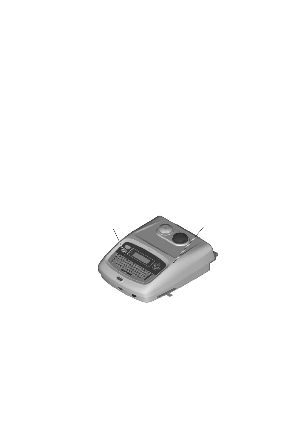
The printer has a stainless steel enclosure, known as the printer cabinet (see
Figure 1-1 below) that houses the following:
• Electronics module
• Ink system
• Power supply
• Integral printer control panel (see Figure 1-1 below)
A
49142
A Printer Control Panel
B Printer Cabinet
Figure 1-1 Linx 4900 Ink Jet Printer
The printhead is attached to the rear of the printer cabinet by a flexible
conduit.
During operation, the printer is located adjacent to a production line to
allow printing onto the product as it passes the printhead. A product sensor
(such as a photocell) is normall y u sed to detect th e pres ence o f the p roduct
and synchronize printing.
B
MP65492–1 1 Linx 4900 Operating Manual
Page 21

Chapter 1: Introduction
1.1.2 Printer System Features
Stainless Steel Printer Cabinet
• Secure front opening prevents unauthorized internal access
• Smooth curved shape aids wash-down and minimizes dirt traps
• Protected to IP55 (International Protection rating against dust and
water)
• External access to clean or replace the air filter, and mistake-proof ink
and solvent addition
Operating Simplicity
• Convenient front panel ‘power on’ button
• Easy startup and shutdown requires minimal operator intervention
• Messages are easily created using the full size keyboard, Function
keys and General Control keys
Printhead Design
• Robustly designed for industrial environments
• Minimal ink build-up; longer intervals between cleaning
• Hermetically sealed and permanently attached to the printer by a
2-metre length of robust conduit (optional l y 4-metre l engt h)
• Optimized printhead geometry for high quality, high speed printing
Printhead Options
• Ultima: optimized for 1 or 2 lines of text/graphics
• Ultima plus: for pigmented inks; optimized for 1 or 2 lines of text/
graphics
Viscosity Control
• Sophisticated system for monitoring and controlling ink viscosity at
the printhead
Diagnostics
• On-screen system event messaging and event log
• Built-in diagnostics functions
Power Down Facility
• Power down function automatically switches the printer off once the
printhead self-cleaning cycle is completed at the end of a shift
Product Sensors and Encoders
• Uses a product detection device (such as a photocell) to detect the
presence of a product and synchronize printing
• Uses a shaft encoder to provide a constant print width regardless of
line speed (combats conveyor speed fluctuation)
Choice of Font and Character Height
• New flexi-font capability for easy message size and print adjustment
• Wide range of character heights and speeds
Linx 4900 Operating Manual 2 MP65492–1
Page 22

Chapter 1: Introduction
1.2 Operating the Printer
Printer operations are controlled from the front of the printer, using the
Printer Control Panel (see Figure 1-1 on page 1), which has a full size
keyboard, General Control keys, LED indicators and an LCD (liquid
crystal display), known as the printer ‘Display’.
1.2.1 Printer Display Features
Function Key Driven Interface
• Simple menu-based user interface
• Keyboard shortcuts provide direct access to key printer functions
• Easy access to message creating and editing functions
• WYSIWYG message disp la y
Password Protected Functionality
• Access to printer functions can be controlled by the password
controlled user levels
• Three user levels to suit the needs and authority of users
Current Message Screen
• Main work area provides access to all printer functions
• View current message at all times
Message Storage
• Up to 50 message capacity
• Easy message selection with preview facility
MP65492–1 3 Linx 4900 Operating Manual
Page 23
Chapter 1: Introduction
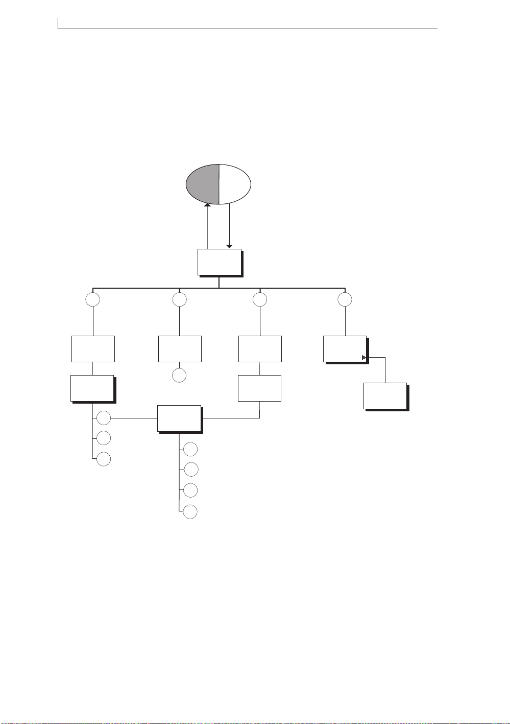
1.2.2 Navigating the System Menus
The following illustration gives an overview of the system m e nus and
screens. It shows how you can navigate between the menus and screens
using the function keys [F1], [F2], [F3] and [F4], and the tasks you
perform.
For full details of the system menu hierarchy, refer to Appendix B, ‘Printer
Controls and System Menus’.
Power
Off
CURRENT
MESSAGE
SCREEN
49057
Power
On
Select, edit or delete
F1
message
OR
Stop printing
SELECT
MESSAGE
SCREEN
MESSAGE
OPTIONS
F1
F2
F3
Select message
for printing
Delete message
F2
PRINT
STATUS
SCREEN
F1
EDIT
MESSAGE
F4
Check
printer status
View Event List
Set font size
F1
F2
Bold on/off
F3
Specify field type
Save message and exit
F3
NEW
MESSAGE
SCREEN
MESSAGE
TYPE
MENU
Create
new message
Figure 1-2 Navigating the System Menus
F4
SETUP
MENU
Change
system setup
DIAGNOSTICS
MENU
Perform
diagnostic tasks
Linx 4900 Operating Manual 4 MP65492–1
Page 24

Chapter 1: Introduction
1.3 About Continuous Ink Jet Printing
What is continuous ink jet printing?
Continuous ink jet printing is a non-contact form of high-speed printing
used to apply variable information such as dat es, text , bat ch codes , prod uct
names and logos to individual products on the production line. This
printing process is fast and versatile and can print on most materials
regardless of size, shape and texture.
How do Linx printers work?
The printer works by propelling a jet of conductive ink through a hole in
the printhead nozzle. Before the ink exits the nozzle, it is pulsed
(modulated) to produce a constant stream of identical ink drops. These
drops are emitted from the printhead in lines known as ‘rasters’. Each
raster has a certain maximum number of drops that determines the
potential height of a character.
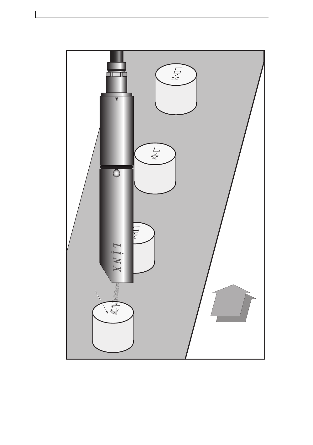
The drops are selectively charged and deflected. A character is formed
from the ink drops emitted from the printhead and built up from successive
rasters as the substrate travels past the printhead to form a print pattern (as
illustrated in Figure 1-3 on page 6). Undeflected drops are recirculated.
About ink viscosity and time of flight
Precise placement of drops is dependent on the speed and amount of
deflection of the drops as they travel between the deflector plates. For this
reason, the printer constantly monitor s the time of flight (T OF) of the drops
and compares it with the optimum (TOF Reference) value. The ink
pressure is increased or decreased, thus maintaining the correct speed of
drops for accurate placement and, therefore, quality of print.
MP65492–1 5 Linx 4900 Operating Manual
Page 25
Chapter 1: Introduction
Direction of Conveyer Travel
ULTI MA
49203
ULTIMA
Print pattern
being created
Direction of Conveyer Travel
Figure 1-3 Printhead in Operation
Linx 4900 Operating Manual 6 MP65492–1
Page 26

Chapter 1: Introduction
1.4 Password Security System
The password system can be used to control operator access to the 4900
printer functions. It can either be switched on to activate the PASSWORD
screen and enforce password entry to certain printer functions, or it can be
switched off at a particular ‘user level’. The three user levels are Level A,
Level B and Level C:
Level A
This level provides user access to basic functions, such as selecting a
message to print, starting and stopping the printer. No password is
required.
Level B
Operating at this user level provides user access to most printer functions
including creating and editing messages.
Level C
Operating at this user level allows full user access to all printer functions
including changing the line settings.
MP65492–1 7 Linx 4900 Operating Manual
Page 27

Chapter 1: Introduction
This page left blank intentionally
Linx 4900 Operating Manual 8 MP65492–1
Page 28

Chapter 2: Getting Started
2 Getting Started
Level A
Level B
Level C
This chapter is designed for anyone who is new to the 4900 printer. It
introduces you to some of the fundamental controls and indicators of the
printer and aims to quickly get you started with some day-to-day printer
operations.
MP65492–1 9 Linx 4900 Operating Manual
Page 29
Chapter 2: Getting Started
2.1 Before You Start
CAUTION: You must read the ‘Safety’ section at the front of this
manual before attempting to use the 4900 printer. If you are in any
doubt, particularly where safety issues arise, please contact Linx or
your Linx approved distributor.
2.1.1 Installation
The 4900 printer system should already be unpacked, installed and set up
by a Linx approved Service Engineer. If the printer has been relocated or
changes to the production line are made, information on how to install and
set up the printer can be found in Appendix A, ‘Installation and Setup’.
2.1.2 Power Connection
The power supply should already be connected when you come to use the
printer.
WA RNING: IF THE PRINTER IS NOT AL READY
CONNECTED AND YOU ARE IN ANY DOUBT AS TO YOUR
ABILITY TO CONNECT POWER TO THE PRINTER,
CONTACT YOUR SUPERVIS OR FOR GUIDANCE.
2.1.3 Mains Power Supply Switch
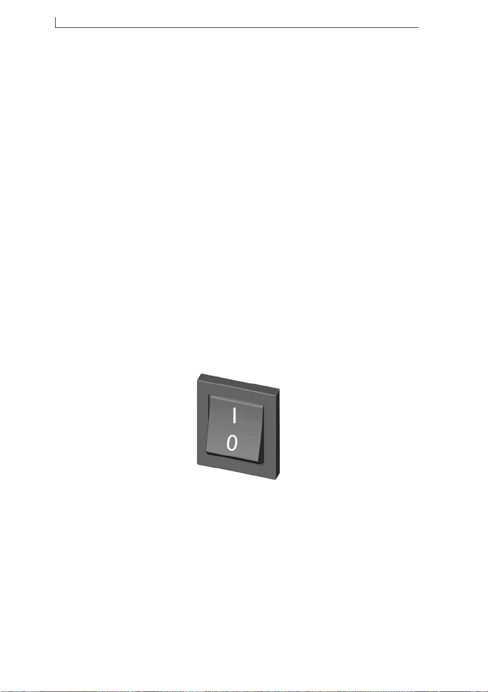
The mains power supply switch at the rear of the printer should already be
set to the On position ( I ) when you come to use the printer (see Figure 21 below), so you will not normally need to touch this switch again.
49145
Figure 2-1 Mains Power Supply Switch (On/Off Rocker Switch)
WA RNING: WHILE THE MAI NS POWER SUPPLY SWITCH
IS SET TO THE ON POSITION ( I ) , MAINS VOLTAGES ARE
STILL PRESENT WITHIN THE PRINTER CABINET.
Linx 4900 Operating Manual 10 MP65492–1
Page 30
Chapter 2: Getting Started
2.2 Switching on and Starting Up
2.2.1 Switching the Printer On
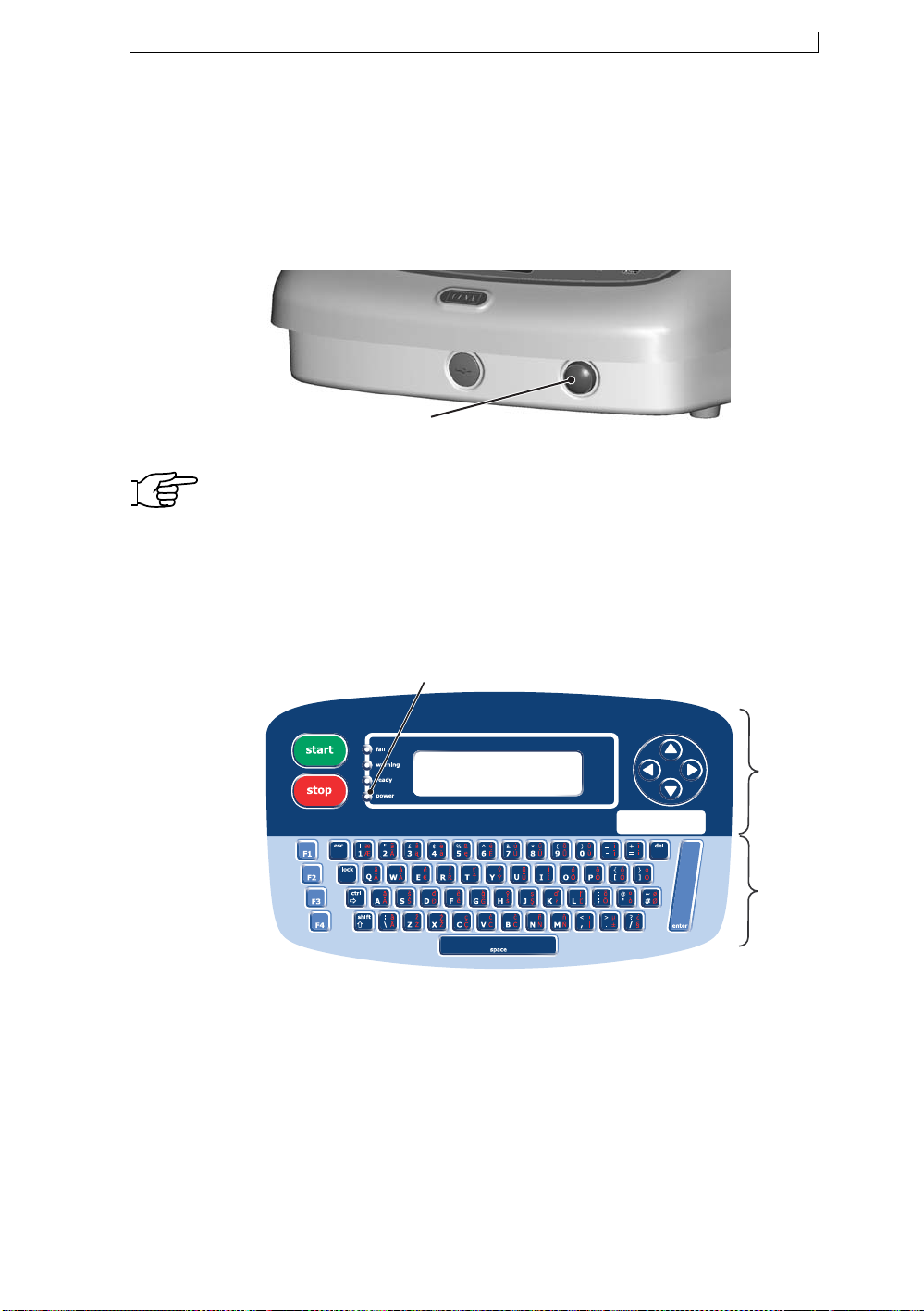
The printer is started up by pressin g and ho lding th e front power butto n for
at least 2 seconds.
49152
'Power On' Button
Figure 2-2 Front Power On Button
NOTE: If the printer fails to start up immediately after the front power
button is released, check that the mains power supply switch at
the rear of the printer is set to the On position; see Figure 2-1 on
page 10. If necessary, switch on this mains power supply switch.
2.2.2 Checking the Power Indicator
Confirm that the printer has power applied. To do this, check that the green
LED power indicator on the printer control panel is lit.
A
49049
A Power LED indicator
B General Control keys and Display
C Keyboard and Function keys
Figure 2-3 Printer Control Panel
B
C
MP65492–1 11 Linx 4900 Operating Manual
Page 31
Chapter 2: Getting Started
About
LED Indicators
The four LED indicators are printer system status indicators. They light to show certain printer
system conditions:
● fail
● warning
● ready
● power
Red Serious printer failure. It may be necessary to contact your local Linx
distributor.
Red Printer warning. A warning message is displayed on the Status line of
the Display.
Green Jet is running and the printer is ready to print. This LED switches off
when printing is stopped (however, the jet may still be running).
Green Power supply to printer is on, and the printer is switched on.
2.2.3 Viewing the Power-up Sequence
The printer automatically powers up when the front power button is
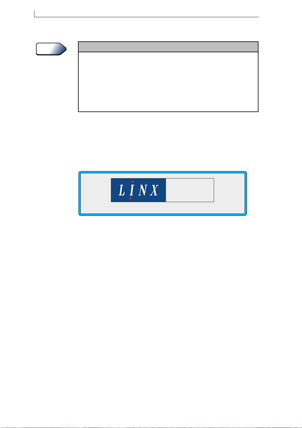
pressed. It carries out a power-up sequ ence, during which a ‘Spl ash’ screen
(Figure 2-4) appears on the Display showing the progress of the sequence
and the software version.
4900
SS
v1.0
49048
Figure 2-4 Startup Splash Screen
Once the power-up sequence is complete, the CURRENT MESSAGE
screen is displayed.
Linx 4900 Operating Manual 12 MP65492–1
Page 32
Chapter 2: Getting Started
2.3 Introducing the Current Message Screen
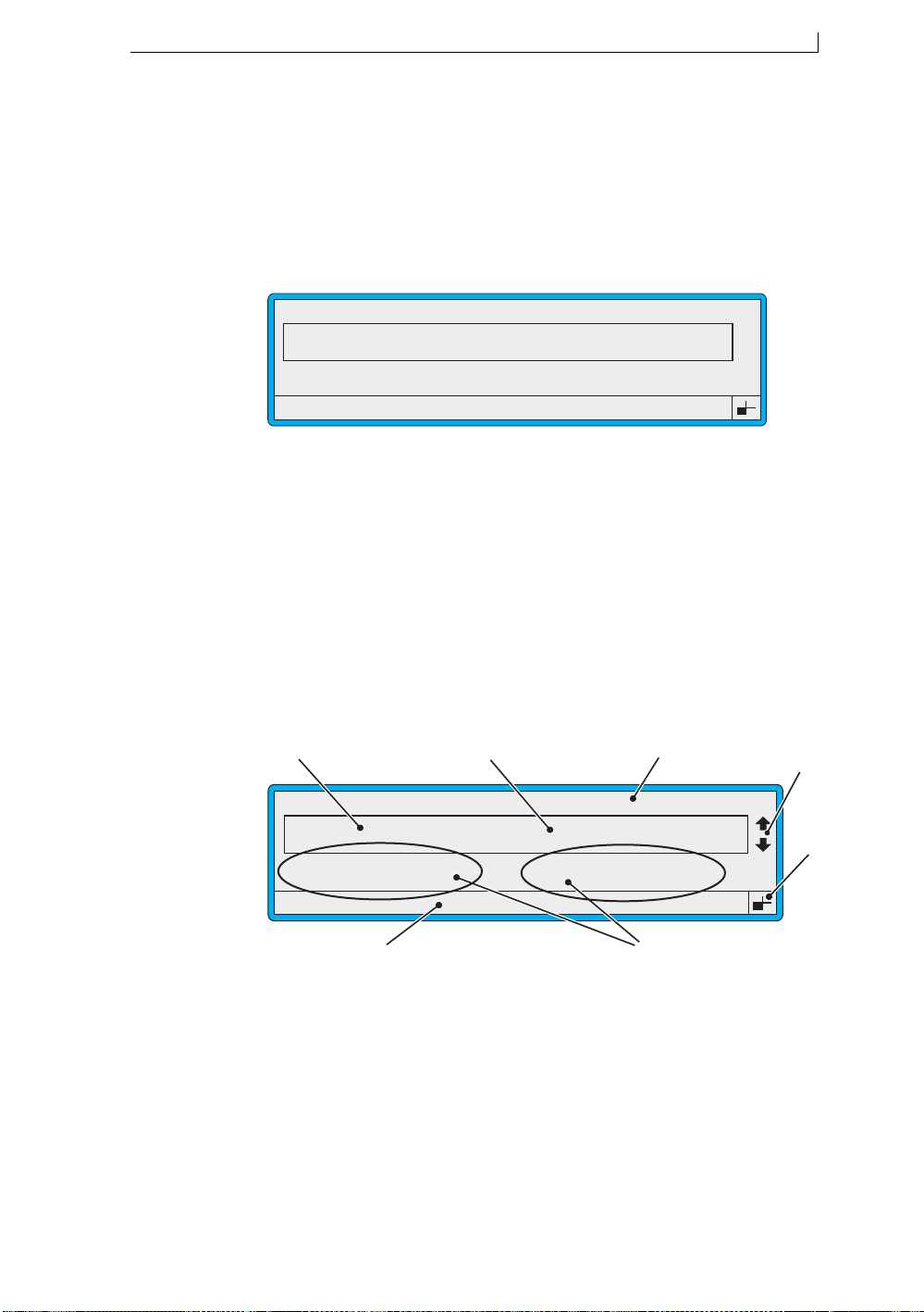
The CURRENT MESSAGE screen is the first screen displayed once the
printer completes the power-up sequence. It displays the current message
and shows the options available to you:
CURRENT MESSAGE : MESSAGE 1
LINX PRINTING
F1 : Change Message
F3 : New Message
F1 Select or change a message
F2 Check the printer status
F3 Create a new message
F4 Change the system setup
Figure 2-5 Current Message Screen
F2 : Check Status
F4 : Change Setup
49008
The CURRENT MESSAGE screen is the starting point for all printer
operations.
2.3.1 Getting to Know the Printer Display
The following example shows the main features and indicators displayed
in the CURRENT MESSAGE screen.
A
CURRENT MESSAGE : MESSAGE 1
B
C
LINX PRINTING
F1 : Change Message
F3 : New Message
Error 3.04 Solvent Low
G
ACurrent Message
B Message Display Area
C Current Message Name
D Message Selection Cursor Indicators
E Keyboard Status Indicator
F Options
G Status Line
Figure 2-6 Current Message Screen Indicators
F2 : Check Status
F4 : Change Setup
F
49009
D
E
MP65492–1 13 Linx 4900 Operating Manual
Page 33
Chapter 2: Getting Started
2.4 How to Print a Message
The sequence of tasks in this section shows you how to select a message
and then start and stop printing.
NOTE: These tasks assume that at least one message has been created,
saved and printed. You should contact your supervisor if no
messages have been set up.
2.4.1 To Select a Message
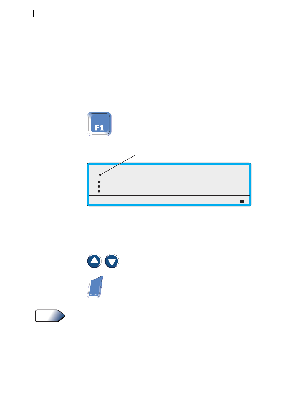
1. At the CURRENT MESSAGE screen, press the [F1] function key:
The SELECT MESSAGE screen is displayed:
Tip
Menu Cursor
SELECT MESSAGE
MESSAGE 1
>
MESSAGE 2
MESSAGE 3
MESSAGE 4
Figure 2-7 Menu Cursor at Select Message Menu
2. At the SELECT MESSAGE screen, use these control keys to select a
message from the list:
Press... To do this...
Scroll through the list, moving the menu cursor
() to the message you want.
At the SELECT MESSAGE screen, you can type the first letter of the
message name to quickly find the message you want.
>
Select the message.
49101
Linx 4900 Operating Manual 14 MP65492–1
Page 34
Chapter 2: Getting Started
Tip
Menu Cursor
The Menu Cursor is the ‘greater than’ symbol (>) found on system menus and screens. It
indicates the current option by replacing the bullet to the left of the option name.
You move the Menu Cursor to the option you want by pressing the ‘up’ and ‘down’ cursor
keys. Once the Menu Cursor is positioned at the option you want, press the [enter] key to
select it.
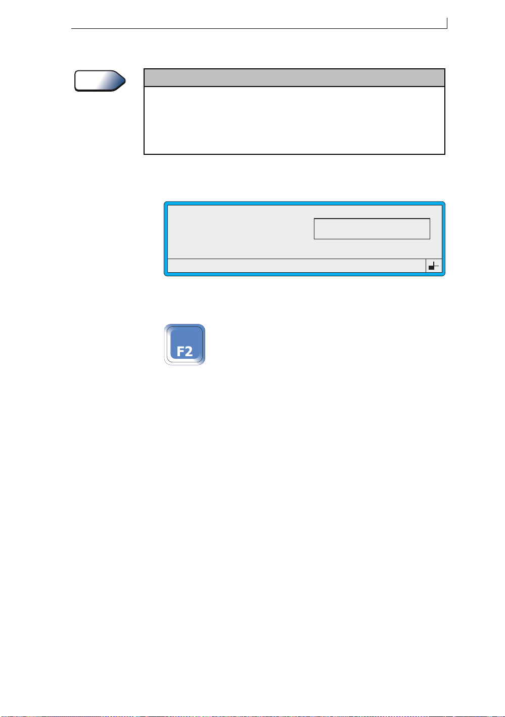
The MESSAGE OPTIONS screen is displayed show ing a previ ew of
the message selected:
49016
MESSAGE OPTIONS : MESSAGE 1
F1 : Edit
F2 : Select
F3 : Delete
LINX PRINT
Figure 2-8 Message Options Screen
3. At the MESSAGE OPTIONS screen, press the [F2] function key:
The CURRENT MESSAGE screen is redisplayed, showing the
selected message as the current message.
MP65492–1 15 Linx 4900 Operating Manual
Page 35
Chapter 2: Getting Started
2.4.2 To Start Printing
1. Select a message to print. Refer to previous section ‘To Select a
Message’ for instructions.
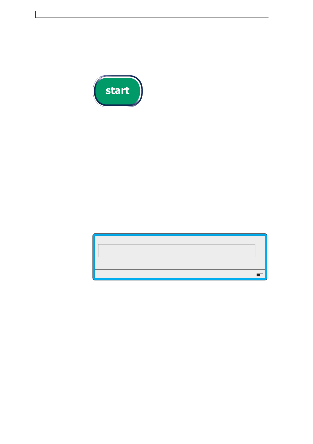
2. Press the [start] key:
The printer starts up the jet, and the Status Line displays the message
“Starting Jet : Please Wait”.
When startup is complete:
• The message “Starting Jet : Please Wait” disappears from the
status line
• The options on the left side of the screen change to display “F1 :
Stop Print” and “Status : Printing” (see Figure 2-9 below)
• The green Ready LED indicator on the Printer Control Panel
lights
• The printer starts printing (actual printing is controlled by the line
settings configured for your production line. See ‘Line Settings’
on page 30 for further information )
49058
CURRENT MESSAGE : MESSAGE 1
LINX PRINTING
F1 : Stop Print
Status : Printing
Figure 2-9 Current Message Screen—When Printing
F2 : Check Status
F4 : Change Setup
Linx 4900 Operating Manual 16 MP65492–1
Page 36

2.4.3 To Stop Printing
1. Press the [F1] function key:
The message “Stop Print : Please Wait” is displayed briefly in the
Status Line, then printing stops.
Once printing stops:
• The options on the left side of the CURRENT MESSAGE
screen are redisplayed (see Figure 2-6 on page 13)
• The printer status changes to “Jet Running”
• The green Ready LED indicator on the Printer Control Panel
extinguishes
If you want to... Do this...
Restart printing Press the [start] key
View the status of the printer Press the [F2] key
Chapter 2: Getting Started
Stop the jet running See the section ‘To Shut Down the
Jet’ on page 21 for instructions
MP65492–1 17 Linx 4900 Operating Manual
Page 37
Chapter 2: Getting Started
2.5 Working with the System Menus
Level B
Level C
The tasks in this secti on show y ou how to navigate t he syst em menus, en ter
the password and how to select and change menu options.
2.5.1 To Enter the Password
Whenever the PASSWORD screen is displayed, you need to enter a
password to continue:
49300
PASSWORD
Enter Password > _
Figure 2-10 Password Screen
1. At the PASSWORD screen, type in the password then press the
[enter] key to confirm your entry.
NOTES:
1. You need the password you were given during your initial printer training.
2. If you enter the password incorrectly, the message “Invalid
Password” is displayed in the Status Line. Re-enter the
password and press the [enter] key.
2.5.2 To Change the System Time
NOTE: This task assumes that printing has been stopped. If necessary,
refer to the previous section for instructions on how to do this.
1. At the CURRENT MESSAGE screen, press the [F4] function key:
NOTE: If the Password system is switched On, the PASSWORD screen
is displayed at this point and you must enter your password to
continue. See ‘To Enter the Password’ above.
Linx 4900 Operating Manual 18 MP65492–1
Page 38
Chapter 2: Getting Started
The SETUP menu is displayed:
Password
>
Print Height
Print Width
Print Delay
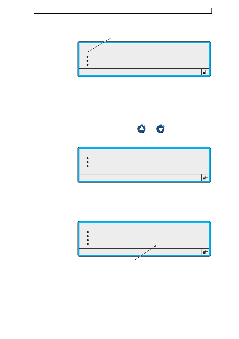
Menu Cursor
SETUP
: Off
: Normal
: 0
: 16
49150
Figure 2-11 Menu Cursor at Setup Menu
NOTES:
1. System menus display four options at a time.
2. The menu cursor always rests beside the menu option that was
selected last time the menu was displayed (accessed).
3. At the SETUP menu, press the and keys to move the menu
cursor to the Set Time option:
49069
SETUP
Print Count
Reverse Message
Bold Ratio
>
Set Time
: 9
: Off
: 1
: 10:16
Figure 2-12 Setup Menu: Set Time Option
4. Press the [enter] key to select the Set Time option.
The menu cursor moves to the setting on the right side of the screen:
49105
SETUP
Print Count
Reverse Message
Bold Ratio
Set Time
Cursor at the Set Time setting
: 9
: Off
: 1
> 15:40
Figure 2-13 Cursor at Set Time Setting
5. At the Set Time setting, enter the current time by overtyping, for
example, 15:40, then press the [enter] key to confirm your entry.
6. Press the [esc] key to return to the CURRENT MESSAGE screen.
MP65492–1 19 Linx 4900 Operating Manual
Page 39
Chapter 2: Getting Started
2.6 Typing Keyboard Characters
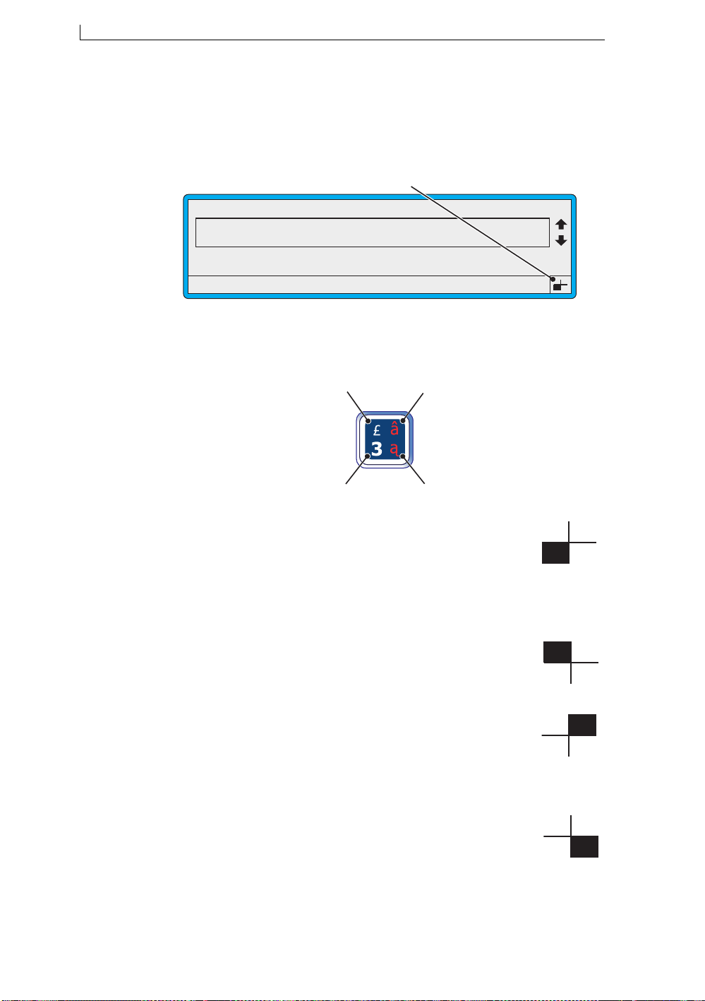
As you type keyboard characters, the keyboard status indicator allows you
to quickly see which character will be displayed when a keyboard key is
pressed:
CURRENT MESSAGE : MESSAGE 1
LINX PRINTING
F1 : Change Message
F3 : New Message
Figure 2-14 Keyboard Status Indicator: Default Position
It shows you which of the four keyboard key character positions is
currently active:
Keyboard Status Indicator
F2 : Check Status
F4 : Change Setup
49236
B
A
A Standard characters (uppercase and numbers).
Simply press the key showing the required character on the
bottom left of the key. This is the default position (mode).
T o reset the keyboard to Stan dard characters, simply reverse the
locking action (as described below) by repeating the same
keystrokes.
B Shifted characters (lowercase)
Hold the [shift] key down and press the key showing the
required character on the top left of the key.
To lock the keyboard in this mode, hold the [shift] key down
and press the [lock] key. To unlock, repeat this locking action.
C Control and Shifted characters
Hold the [ctrl] key + the [shif t] key down and press the required
character on the top right of the key. To lock the keyboard in
this mode, hold the [ctrl] key + [shift] key down and press the
[lock] key. To unlock, repeat this locking action.
D Control characters
Hold the [ctrl] key down and press the key showing the
required character on the bottom right of the key.
T o lock the keyboar d in thi s mode, hold the [ct rl] key down an d
press the [lock] key. To unlock, repeat this locking action.
C
49149
D
Figure 2-15 Typing Keyboard Characters
Linx 4900 Operating Manual 20 MP65492–1
Page 40
Chapter 2: Getting Started
2.7 Shutting Down and Switching Off
WARNING: DO NOT USE THE MAINS POWER SUPPLY
SWITCH (ROCKER SWITCH AT THE REAR OF THE
PRINTER) TO STOP THE PRIN TER, EXCEPT IN AN
EMERGENCY. SHUTDOWN AND POWER OFF SHOULD
ALWAYS BE CARRIED OUT FROM THE PRINTER
CONTROL PANEL.
2.7.1 To Shut Down the Jet
1. Press the [stop] key:
The printer initiates a jet shutdown procedure, which takes
approximately 3 min ut es. During jet shu t down the message “S t opp i ng
Jet : Please Wait” is displayed in the Status Line.
When the printer has finished the jet shutdown proced ure, the message
changes to “Jet Stopped : Press Stop to Power Down”.
2.7.2 To Power Down and Switch Off
Powering Down and Switching Off Automatically
The ‘Auto Power Down’ function is set, as a default, to initiate
automatically, so that after the jet is shut down, the printer automatically
goes into power down mode (see Figure 2-16) and switches off the printer:
AUTO POWER DOWN
About to power down in:
10 seconds
Press any key to resume
Figure 2-16 Auto Power Down Screen
When the countdown reaches zero, the po wer to the pr inter is switched o ff ,
and the printer Display and the Power LED indicator extinguish.
NOTE: that the mains power supply switch (rocker switch) at the rear of
the printer remains in the On position.
49023
MP65492–1 21 Linx 4900 Operating Manual
Page 41
Chapter 2: Getting Started
About
Auto Power Down
Auto Power Down
setting is configured ON for the printer, and power down is automatically initiated after
Down
the jet is shut down.
When the printer goes into power down mode, a countdown dialog is displayed and you can
press any key to stop the power down sequence and resume if you wish.
Note that
method, a customized delay time can be enforced.
is a configurable function of the printer. As a default, the
Auto Power Down
can also be configured using the
Printer Idle
Auto Power
setting. Using this
NOTES:
1. Initiation of automatic power down is determined by the options
selected in the Auto Power Down screen. See Chapter 5,
‘Changing the System Setup’ for details.
2. If you are unsure whethe r or not to switch t he printer off, you
should consult your supervisor.
Initiating Power Down and Switching Off Manually
If the ‘Auto Power Down’ function is not enabled or you wish to manually
switch off the printer:
1. Shut down the jet. To do this, press the [stop] key.
2. Check that the printer status on the PRINT STATUS screen is ‘Jet
Off’.
3. Press the [stop] key:
The following screen is displayed:
49024
POWER DOWN
Switch off power?
F1 : Yes
F2 : No
Figure 2-17 Power Down Screen
4. Press the [F1] function key to select Yes (alternativ ely, press the [F2]
function key to select No and return to the CURRENT MESSAGE
screen).
Linx 4900 Operating Manual 22 MP65492–1
Page 42

Chapter 2: Getting Started
The power to the printer is switched off, and the printer Display, and
the Power LED indicator extinguish.
Note that the mains power supply switch at the rear of the printer
(rocker switch) remains in the ON position.
WARNING: WHILE THE MAINS POWER SUPPLY SWITCH
IS SET TO THE ON POSITION ( I ) , MAINS VOLTAGES ARE
STILL PRESENT WITHIN THE PRINTER CABINET.
2.7.3 Emergency Stop
In an emergency situation you may need to stop the printer quickly. Use
one of the following methods to do this:
• Switch the printer’ s wall mounted electrical isolator to the off position
to shut off the electricity supply to the printer
• Switch the printer mains power supply switch at the rear of the printer
to the ‘0’ (off) position
CAUTION: Wherever possible, do not leave the printer in this state
for too long as this may result in ink blockages. You should restart the
jet and carry out a normal shutdown using the correct procedure as
soon as possible.
MP65492–1 23 Linx 4900 Operating Manual
Page 43

Chapter 2: Getting Started
This page left blank intentionally
Linx 4900 Operating Manual 24 MP65492–1
Page 44

Chapter 3: Day-to-Day Operations
3 Day-to-Day Operations
Level A
Level B
Level C
This chapter describes the day-to-day printer operations, such as working
with the current message, selecting a message, starting and stopping
message printing, and viewing the printer status. It also describes how to
handle system ‘event’ messages and work with printer system passwords.
NOTE: If you are new to the 4900 p rinter , yo u should f irst read Ch apter 2,
‘Getting Started’ to familiarize yourself with the fundamental
printer controls and indicators, and to start performi ng some basic
printer operations.
MP65492–1 25 Linx 4900 Operating Manual
Page 45

Chapter 3: Day-to-Day Operations
3.1 Introducing the Current Message Screen
The CURRENT MESSAGE screen is the starting point for all printer
operations, and during day-to-day operations the printer display typically
remains at this screen.
The following example shows the main features and indicators displayed
on the CURRENT MESSAGE screen:
A
CURRENT MESSAGE : MESSAGE 1
B
C
49009
D
LINX PRINTING
F1 : Change Message
F3 : New Message
Error 3.04 Solvent Low
G
Figure 3-1 Current Message Screen Indicators
Feature/Indicator... Description...
A Current Message Message currently selected for
B Message Display Area Area where the current message is
C Current message name Name assigned to the current message.
D Message Selection Cursor
Indicators
F2 : Check Status
F4 : Change Setup
F
printing.
displayed.
Indicates that you can press the Up
[ ] and Down [ ] cursor keys to
scroll through the message list and
view the stored messages.
E
E Keyboard Status Indicator Symbol showing which character will
be displayed when a keyboard key is
pressed.
F Options Indicates the printer functions
available to you. To select an option,
you press the associated function
key—[F1], [F2, [F3] or [F4].
G Status Line Displays status messages, and printer
warning and fault messages, known as
‘event messages’.
Linx 4900 Operating Manual 26 MP65492–1
Page 46
Chapter 3: Day-to-Day Operations
3.2 Selecting and Printing Messages
This section describes how to select a message for printing, then start and
stop message printing.
NOTE: These tasks assume that at least one message has been created and
saved. You should contact your supervisor if no messages have
been setup.
3.2.1 Before You Start Printing
• Check that the message displayed in the CURRENT MESSAGE
screen is the message you wish to print.
To choose another message for printing, you can select one from the
list of existing messages (see ‘To Select a Message for Printing’
below).
3.2.2 To Select a Message for Printing
NOTE: Printing must be stopped to select a message. If necessary, press
the [F1] function key to stop printing.
Tip
To select a message, use one of the following methods:
Method 1: Select and Preview
1. At the CURRENT MESSAGE screen, press the [F1] function key.
The SELECT MESSAGE menu is displayed:
Menu Cursor
SELECT MESSAGE
MESSAGE 1
>
MESSAGE 2
MESSAGE 3
MESSAGE 4
Figure 3-2 Select Message Menu
NOTES:
1. The menu cursor () indicates which message in the list is the
currently selected message.
2. The SELECT MESSAGE menu lists all messages
alphabetically, showing just four messages at a time.
3. At the SELECT MESSAGE menu, scr oll thr ough the list using the
Up [ ] or Down [ ] cursor keys until the cursor rests at the message
you want.
Type in the first character of the message name to quickly find the
message you want. Note that the letter you enter is case sensitive.
4. Press the [enter] key.
>
49101
MP65492–1 27 Linx 4900 Operating Manual
Page 47
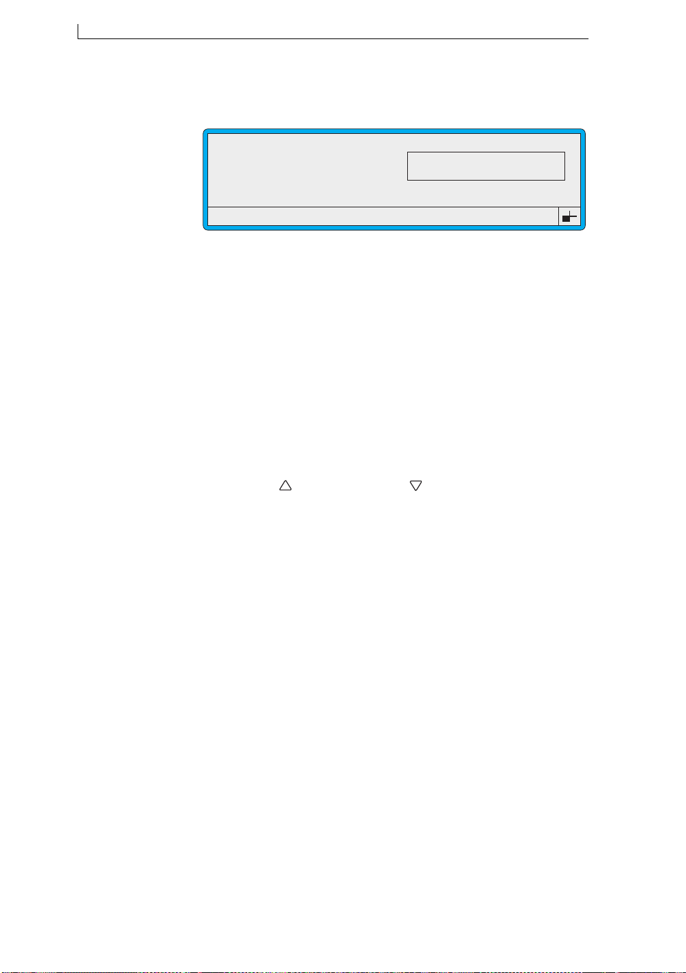
Chapter 3: Day-to-Day Operations
The MESSAGE OPTIONS screen is displayed, sho wing a preview of
the message you selected:
MESSAGE OPTIONS : MESSAGE 1
F1 : Edit
F2 : Select
F3 : Delete
Figure 3-3 Message Options Screen
Note that in some cases, particularly when large messages are
displayed, only the first part (leftmost) of the message is shown in the
preview window.
5. At the MESSAGE OPTIONS screen, press the [F2] function key to
select the message.
The CURRENT MESSAGE screen is redisplayed, showing the
selected message.
Method 2: Scroll to Select
1. At the CURRENT MESSAGE screen, check that the Message
Selection Cursor Indicators are visible (see Figure 3-1 on page 26),
if not, press the [F1] function key to stop printing.
2. Press the Up [ ] key and the Down [ ] key to scroll through the list
of stored messages. With each key press, the next message is
displayed in the Message Display Area, and the message name
changes accordingly.
49016
LINX PRINT
Linx 4900 Operating Manual 28 MP65492–1
Page 48
3.2.3 To Start Printing
1. Press the [start] key.
The printer starts up the jet, and the Status Line displays the message
“Starting Jet : Please Wait”.
When startup is complete:
• The message “Starting Jet : Please Wait” disappears from the
status line
• The options on the left side of the screen change to display “F1 :
Stop Print” and “Sta tus : Print i ng” ( see Figure 3-4 below)
• The green Ready LED indicator on the Printer Control Panel
lights
• The printer starts printing
CURRENT MESSAGE : MESSAGE 1
Chapter 3: Day-to-Day Operations
49058
See Also
LINX PRINTING
F1 : Stop Print
Status : Printing
Figure 3-4 Current Message Screen—When Printing
NOTE: Actual printing is controlled by the line settings configured for
your production line. For further information, see ‘Line Settings’
on page 30).
F2 : Check Status
F4 : Change Setup
MP65492–1 29 Linx 4900 Operating Manual
Page 49
Chapter 3: Day-to-Day Operations
Printer Status
The action taken by the printer when the [start] key is pressed is
determined by the current printer status. The following table shows what
happens when the printer is started and stopped:
Initial Printer
Status
Jet Off
Jet Running
Printing
KEY: * Actual printing is controlled by the Line Settings configured for your
production line.
** When the Auto Power Down function is set to On.
Pressing
[start] key
Starts jet
Starts printing
Starts printing
*
*
Pressing
[F1] key
Stops printing
49059
Pressing
[stop] key
Initiates Power
Down
Shuts down jet
Initiates Power
Down
**
Stops printing
Shuts down jet
Initiates Power
Down
**
See Also
Figure 3-5 Starting and Stopping Printing
Line Settings
When the printer is in printing mode (printer Status is “Printing”—see
Figure 3-4 on page 29), the time when a message prints, and the rate of
print (printing speed) is controlled by the settings of the Primary Trigger
option and the Shaft Encoder option in the SETUP menu, as follows:
• The trigger that initiates a print is configured using the Primary
Trigger option. The trigger can be some form of product sensor such
as a photocell, or none (continuous print). A product sensor is used to
detect the presence of the product to be printed on.
A message is usually printed in response to a trigger signal from the
product sensor, however, there are variations in the way that the
printer interprets a trigger signal.
• The speed that the printer prints at to match line speed is configured
using the Shaft Encoder option. This can be On or Off. A shaft
encoder is a device used for line speed detection.
Refer to Appendix A, ‘Installation and Setup’ for information about using
and setting up product sensors and shaft encoders.
Linx 4900 Operating Manual 30 MP65492–1
Page 50
Chapter 3: Day-to-Day Operations
To check the current line settings, and for further information about your
line setup, see Chapter 5, ‘Changing the System Setup’.
The following table shows when the printer actually prints, depending on
the settings configured for your production line:
Product Sensor Shaft Encoder Printing result
Selected
Not selected
Selected
Not selected
Selected
Not selected
Prints when Product Sensor is
triggered, and Shaft Encoder has
moved set distance.
Prints when Product Sensor is
triggered.
Prints continuously when Shaft
Encoder has moved set distance.
Prints immediately and continuously
irrespective of presence of a
product.
Figure 3-6 Product Sensor/Shaft Encoder Printing Results
3.2.4 To Stop Printing
1. Press the [F1] function key:
49060
The message “Stop Print : Please Wait” is displayed briefly in the
Status Line, then printing stops.
The options on the left side of the CURRENT MESSAGE screen are
redisplayed (see Figure 3-1 on page 26), and the printer status chang es
to “Jet Running”.
MP65492–1 31 Linx 4900 Operating Manual
Page 51

Chapter 3: Day-to-Day Operations
3.2.5 To Shutdown the Jet
1. Press the [stop] key:
The printer initiates a jet shutdown procedure, which takes
approximately 3 m in ute s . During jet shut down the message “Stopping
Jet : Please Wait” is displayed in the Status Line.
When the printer has finished the jet shutdown procedure, what
happens next depends on whether or not the ‘Auto Power Down’
function is enabled:
• The ‘Auto Power Down’ function is enabled as a default—after
the jet is shut down, the printer automatically goes into power
down mode and switches the power off. See the next section for
further details
• If the ‘Auto Power Down’ function is not enabled, after the jet is
shut down, the message in the S tatus Line changes to “Jet
Stopped : Press Stop Key to Power Down”
Linx 4900 Operating Manual 32 MP65492–1
Page 52
Chapter 3: Day-to-Day Operations
3.2.6 To Power Down and Switch Off
CAUTION: Always use the correct procedure (described below) to
power down and switch off the printer. Do NOT use the mains power
supply switch (rocker switch at the rear of the printer) to stop the
printer, except in an emergency.
Using the correct procedure ensures that any r ecent changes ar e saved
(and the printhead is automatically cleaned). If you switch off at the
mains, you may lose any recent changes and experience printhead
problems. Thorough cleaning of the printhead will be necessary.
Powering Down and Switching Off Automatically
The ‘Auto Power Down’ function is set, as a default, to initiate
automatically, so that after the jet is shutdown, the printer automatically
goes into power down mode (see Figure 3-7) and switches the power off.
AUTO POWER DOWN
About to power down in:
10 seconds
Press any key to resume
49023
Figure 3-7 Power Down Countdown Screen
When the countdown reaches zero, the power to the printer is switched
off, and the printer Display and the Power LED indicator extinguish.
NOTE: that the mains power supply switch (rocker switch) at the rear of
the printer remains in the On position.
WARNING: WHILE THE MAINS POWER SUPPLY SWITCH
IS SET TO THE ON POSITION ( I ) , MAINS VOLTAGES ARE
STILL PRESENT WITHIN THE PRINTER CABINET.
NOTES:
1. Initiation of automatic power down (i.e. enabling or disabling) is
determined by the options selected in the AUTO POWER
DOWN screen. See Chapter 5, ‘Changing the System Setup’ for
details.
2. If you are unsure whether or not to power the printer off manually,
you shoul d consult your supervisor.
MP65492–1 33 Linx 4900 Operating Manual
Page 53
Chapter 3: Day-to-Day Operations
Initiating Power Down and Switching Off Manually
If the ‘Auto Power Down’ function is not enabled, or you wish to manually
power down the printer:
1. Stop the jet. To do this, press the [stop] key.
2. Check that the printer status on the PRINT STATUS screen is “Jet
Off”. See ‘Viewing the Printer Status’ on page 38.
3. Press the [stop] key:
The following screen is displayed:
49024
POWER DOWN
Switch off power?
F1 : Yes
F2 : No
Figure 3-8 Power Down Screen
4. Press the [F1] function key to select Yes (alternativ ely, press the [F2]
function key to select No and return to the CURRENT MESSAGE
screen).
The power to the printer is switched off immediately, and the printer
Display and the Power LED indicator extinguish.
Note that the mains power supply switch at the rear of the printer
(rocker switch) remains in the ON positi on.
Linx 4900 Operating Manual 34 MP65492–1
Page 54

Chapter 3: Day-to-Day Operations
3.2.7 Emergency Stop
In an emergency situation you may need to stop the printer quickly. Use
one of the following methods to do this:
• Switch the printer’ s wall mounted electrical isolator to the off position
to shut off the electricity supply to the printer
• Switch the printer’s mains power supply switch at the rear of the
printer to the ‘0’ (off) position
Note that if you use either of the above methods of stopping the printer,
you may lose any recent changes made to the printer settings.
CAUTION: Wherever possible, do not leave the printer in this state
for too long as this may result in ink blockages. You should clean the
printhead and restart the jet, then carry out a normal jet shut down
and power down using the correct procedures as soon as possible.
MP65492–1 35 Linx 4900 Operating Manual
Page 55
Chapter 3: Day-to-Day Operations
3.3 Editing the Current Message
All messages are edited using the EDIT MESSAGE screen.
NOTE: Printing must be stopped. If necessary, press the [F1] function key
to stop printing.
3.3.1 To Select the Message for Editing
1. At the CURRENT MESSAGE screen, press the [F1] function key.
The SELECT MESSAGE screen is displayed, with the current
message at the top of the message list, as follows:
MESSAGE 1
>
MESSAGE 2
MESSAGE 3
MESSAGE 4
Figure 3-9 Select Message Screen
2. Press the [enter] key.
The MESSAGE OPTIONS screen is displayed, sho wing a preview of
the message:
MESSAGE OPTIONS : MESSAGE 1
F1 : Edit
F2 : Select
F3 : Delete
49014
SELECT MESSAGE
49016
LINX PRINT
Figure 3-10 Message Options Screen
3. At the MESSAGE OPTIONS screen, press the [F1] function key.
NOTE: If the Password system is switched On, the PASSWORD screen
is displayed at this point and you must enter a password to
continue. See ‘To Enter the Password’ on page 42 for further
details.
Linx 4900 Operating Manual 36 MP65492–1
Page 56
Chapter 3: Day-to-Day Operations
The EDIT MESSAGE s creen is displayed with the selected message
shown in the Message Display Area:
EDIT MESSAGE : MESSAGE 1
LINX PRINTING
F1 : Size 16 FH (Caps)
F3 : Field Type
Figure 3-11 Edit Message Screen
3.3.2 To Edit the Message
1. With the message displayed in the Message Display Area of the EDIT
MESSAGE screen, you edit the message by selecting each field in
turn and making the required changes:
Press this key... To...
[enter] Select a field for editing.
F2 : Bold Off
F4 : Save & Exit
49030
See Also
[shift] + [ ] or [ ], [ ], [ ]
[ ], [ ], [ ] or [ ]
[ctrl] +[], [], [] or []
[F1] Change the character size.
[F2] Switch the bold factor on/off.
[F3] Change the field type.
[F4] Save changes and exit.
[ctrl] + [del] Delete the selected field.
For detailed instructions on how to create and edit all types of message
fields, see Chapter 4, ‘Creating and Editing Messages’.
2. When you have finished, press the [F4] function key to save the
changes and exit.
The CURRENT MESSAGE screen is redisplayed, showing the
edited message.
Move to the start, end, top or
bottom of the message.
Move the cursor up, down, left
or right (by one character).
Move the cursor up, down, left
or right (by one drop).
MP65492–1 37 Linx 4900 Operating Manual
Page 57
Chapter 3: Day-to-Day Operations
3.4 Viewing the Printer Status
The 4900 printer has the foll o win g vis ual guides that show you the cur rent
status of the printer:
• The Status Line at the bottom of the screen (or menu) displays
messages about the operational status of the printer, such as “Starting
Jet : Please Wait”. These are advisory messages that appear as you
work with the printer, starting and stopping printing, stopping the jet,
and so on. The status line also displays system event messages when
certain printer conditions occur, for example, “Error 3.03 Ink Low”.
• The PRINT STATUS screen shows the current printer status
(Printing, Jet Off, Jet Running) as well as the status of the ink and
solvent levels. It also shows the print count and allows you to access
the EVENT LIST screen to view the current system event messages.
3.4.1 To View the Current Printer Status
1. At the CURRENT MESSAGE screen, press the [F2] function key.
2. The PRINT STATUS screen is displayed:
F1 : Event List
49015
PRINT STATUS
Count : 9
Status : Jet Off
Solvent : OK
Ink : OK
Figure 3-12 Print Status Screen
3. At the PRINT STATUS screen:
• Pressing the [F1] key displays the EVENT LIST menu where
active event messages are listed. See ‘To View Events in the List’
on page 41 for details.
This parameter... Indicates...
Count The total number of prints made by the printer.
You can reset or change this number via the
Print Count option in the SETUP menu. See
‘To Reset the Print Count’ on page 39.
Status The operational status of the printer:
Jet Off the jet is stopped.
Jet Running the jet is running, but not
printing.
Printing th e pr inter is printing.
Linx 4900 Operating Manual 38 MP65492–1
Page 58
Chapter 3: Day-to-Day Operations
This parameter... Indicates...
Solvent The solvent level status:
OK solvent level is acceptable.
LOW solvent level is low.
You should add one bottle of solvent. See
Chapter 7, ‘Diagnostics and Maintenance’ for
instructions.
Ink The ink level status:
OK ink level is acceptable.
LOW ink level is low.
You should add one bottle of ink. See Chapter
7, ‘Diagnostics and Maintenance’ for
instructions.
3.4.2 To Reset the Print Count
The Print Count option displays the total number of prints made by the
printer. You can change this figure to reset the count. To do this:
1. At the CURRENT MESSAGE screen, press the [F4] function key.
NOTE: If the Password system is switched On, the PASSWORD
screen is displayed at this point and you must enter a
password to continue.
The SETUP menu is displayed.
2. Scroll through the menu options until the cursor rests at Print Count,
as follows:
SETUP
Print Height
Print Width
Print Delay
>
Print Count
: Normal
: 0
: 16
: 9
49066
Figure 3-13 Setup Menu: Print Count Option
3. T o reset or to change the value, pr ess the [enter] key to select the Print
Count option then overtype the number.
4. Press the [enter] key to confirm your entry.
5. Press the [esc] key to exit.
MP65492–1 39 Linx 4900 Operating Manual
Page 59
Chapter 3: Day-to-Day Operations
3.5 Handling System Events
A system ‘event’ is a message generated by the system when a certain
printer condition occurs. Events are classified as either a Failure, or a
Warning type event.
During day-to-day operation, i f a Failure or a Warning type event occurs, a
message is displayed in the St at us Line at the bottom of the screen (see
Figure 3-14 below), and the printer’s internal beeper is activated to draw
your attention to a particular printer condition that needs attention. The
relevant LED indicator (Fail or Warning) on the Printer Control Panel also
lights.
CURRENT MESSAGE : MESSAGE 1
LINX PRINTING
F1 : Change Message
F3 : New Message
Figure 3-14 System Warning Event Message
F2 : Check Status
F4 : Change Setup
Error 3.03 Ink Low
Status Line
49303
Each event message is numbered for identification and classification as
follows:
This type of event message... Starts with...
System Fail ure 1
Print Failure 2
System Warning 3
NOTE: You should resolve the printer condition as soon as possible. If
necessary , refer to Ap pend ix D, ‘ S ys tem Event Mes sages’ , where
all system events are listed and described.
System events are logged in the ‘Event List’ where they remain until they
are resolved, or until the printer is switched off. See ‘To View Events in the
List’ on page 41 for further information.
Linx 4900 Operating Manual 40 MP65492–1
Page 60
See Also
Chapter 3: Day-to-Day Operations
3.5.1 To View Events in the List
You can view a record of the current system events via the EVENT LIST
menu. These events have occurred since the printer was last switched on.
Events are automatically deleted from the list when the power to the printer
is switched off, following shutdown, or when an event is resolved.
To view events in the list:
1. At the CURRENT MESSAGE screen, press the [F2] function key to
display the PRINT STATUS screen (see Figure 3-12 on page 38).
2. Press the [F1] function key. The EVENT LIST menu is displayed as
follows:
EVENT LIST
>
3.12 Printhead Cover Off
3.04 Solvent Low
Figure 3-15 Event List Menu
Refer to Appendix D, ‘System Event Messages’ for a description of
the system event messages.
3. Press the [esc] key to exit.
49315
Tip
You can use a shortcut key to go to the EVENT LIST menu. To do this,
press [L] at the CURRENT MESSAGE screen.
MP65492–1 41 Linx 4900 Operating Manual
Page 61
Chapter 3: Day-to-Day Operations
3.6 Working with Passwords
The Linx 4900 printer has a password system that allows you to control the
printer functions available to the printer operator. You can elect to work
with the password system On (password controlled access to certain printer
functions), or you can choose to work with the password system switched
Off at a designated ‘user level’.
‘User levels’ determine which printer functions are available; these levels
are Level A, Level B and Level C.
This section describes how to enter a password and how to switch the
password system on or off.
See Also
For information on changin g a pas swo rd, s ee ‘ C hang i ng the Passwords’ in
Chapter 5, ‘Changing the System Setup’.
3.6.1 To Enter the Password
When the password system is switched On, you must enter a password at
the PASSWORD screen to perform certain functions:
49300
PASSWORD
Enter Password > _
Figure 3-16 Password Screen
1. At the PASSWORD screen, type in your password and press the
[enter] key. This must be the valid password for Level B, or Level C.
NOTES:
1. If you enter the password incorrectly, the message “Invalid
Password” is displayed on the S tatus Line. Re-enter the correct
password and press the [enter] key.
2. Passwords are not case sensitive or keyboard sensitive.
3. Use the password you were given during your initial printer
training.
Linx 4900 Operating Manual 42 MP65492–1
Page 62
Chapter 3: Day-to-Day Operations
3.6.2 To Switch the Password System On/Off
The Password function allows you to either switch the password system
Off at a designated user level, or to switch the password system On for
password controlled access to certain functions.
To Switch the Password System Off
When you switch the password system off, operators can access all printer
functions at the designated user level without having to enter a password at
any stage.
1. At the CURRENT MESSAGE screen, press the [F4] function key.
The PASSWORD screen is displayed (see Figure 3-16 on page 42).
2. Type in the password. Note that the password you enter here
determines the user level at which the printer operates (Level B or
Level C) when the password system is switched Off .
3. Press the [enter] key.
The SETUP menu is displayed.
4. Scroll to the top of the SETUP menu until the cursor rests at the
Password option:
SETUP
>
Password
Print Height
Print Width
Print Delay
: Off
: Normal
: 0
: 16
49065
Figure 3-17 Setup Menu: Password Option
5. Press the [enter] key.
6. At the Password option setting, press the Left [ ] or Right [ ]
cursor keys to toggle the setting to Off, then press the [enter] key.
7. Press the [esc] key to exit.
MP65492–1 43 Linx 4900 Operating Manual
Page 63

Chapter 3: Day-to-Day Operations
To Switch the Password System On
When the password system is switched On, a password must be entered to
access certain printer functions. Note that the following instruction
assumes that the password system is Off.
To switch the password system On:
1. At the CURRENT MESSAGE screen, press the [F4] function key.
The SETUP menu is displayed.
2. Scroll to the top of the SETUP menu until the cursor rests at the
Password option (see Figure 3-17 on page 43).
3. Press the [enter] key.
4. At the Password setting, press the Left [ ] or Right [ ] cursor key
to toggle the setting to On, then press the [enter] key.
5. Press the [esc] key to exit.
Linx 4900 Operating Manual 44 MP65492–1
Page 64

Chapter 3: Day-to-Day Operations
3.7 Getting Help
• For help with a syste m message, for example, “3.04 Solvent Low”,
refer to Appendix D, ‘System Event Messages’
• For help with troubleshooting a printer system problem, refer to
Chapter 7, ‘Diagnostics and Maintenance’, and Appendix D, ‘System
Event Messages’
• For any other help, including using the printer or the software, refer
to the ‘Contents’ or ‘Index’ sections to locate the relevant information
MP65492–1 45 Linx 4900 Operating Manual
Page 65

Chapter 3: Day-to-Day Operations
This page left blank intentionally
Linx 4900 Operating Manual 46 MP65492–1
Page 66

Chapter 4: Creating and Editing Messages
4 Creating and Editing Messages
Tip
Level A
Level B
Level C
This chapter describes how to create and edit messages. It is organized into
the following sections:
4.1 ‘Introduction’
4.2 ‘Creating a New Message’
4.3 ‘Getting to Know the EDIT MESSAGE Screen’
4.4 ‘Creating a Text Field’
4.5 ‘Working with Message Fields’
4.6 ‘Selecting, Editing and Deleting Messages’
4.7 ‘Creating a Time Field’
4.8 ‘Creating a Timed Message Field’
4.9 ‘Creating a Sequential Number Field’
4.10 ‘Creating a Date Field’
4.11 ‘Creating a Remote Field’
4.12 ‘Inserting a Logo Field’
4.13 ‘Creating a Message: Worked Example’
If you are new to the 4900 printer and wish to get started creating a
message, go to the section ‘Creating a Message: Worked Example’ on
page 82.
MP65492–1 47 Linx 4900 Operating Manual
Page 67
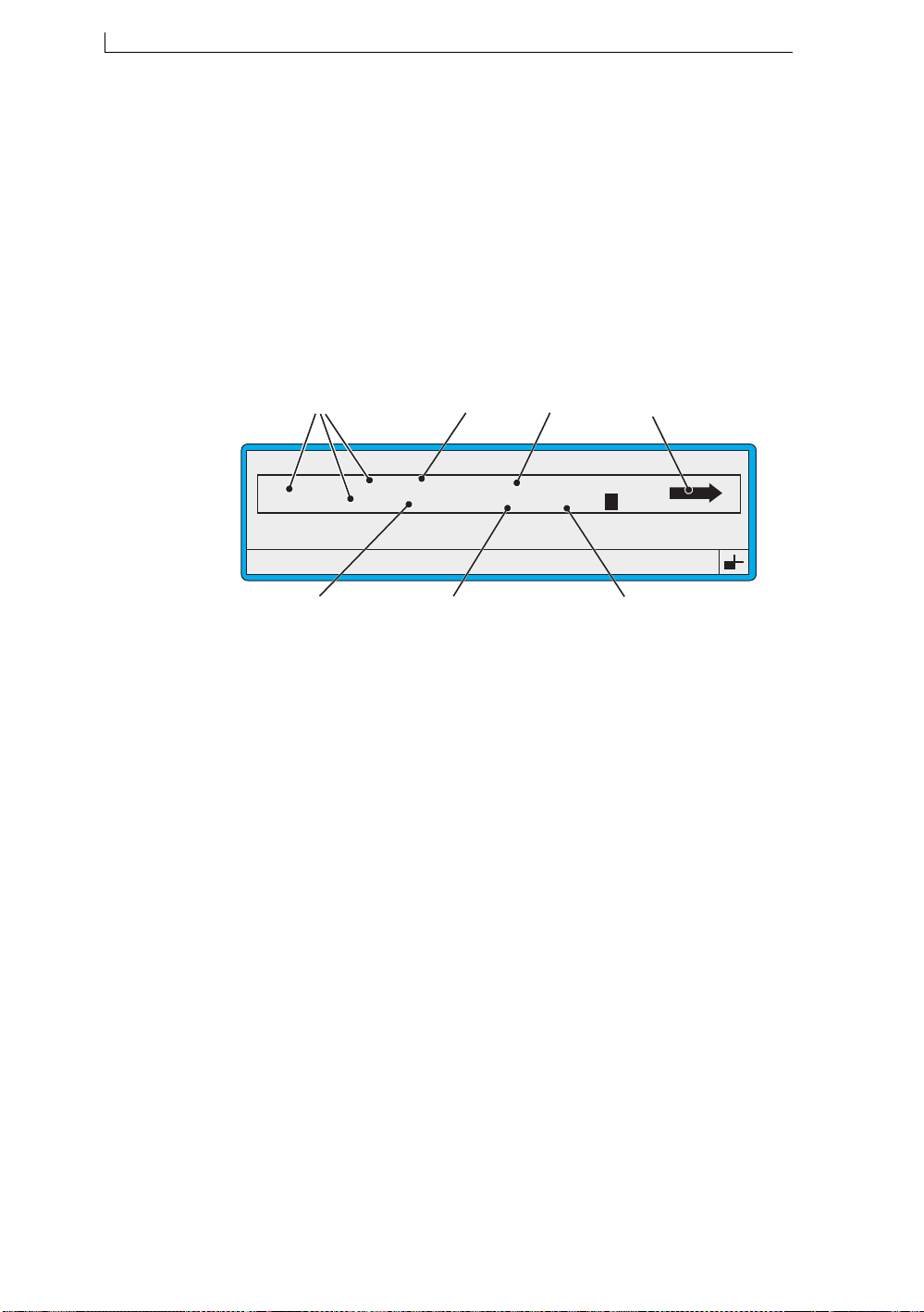
Chapter 4: Creating and Editing Messages
4.1 Introduction
4.1.1 Message Fundamentals
Messages are made up of one or more fields. A message can be a single
field, for example, a text field , or it can contain several fields of varying
type and size.
Text is just one of the field types that you can incorporate into a message;
other types are logos, sequential numbers, time and date, and remote data.
The following illustration shows an example message, as viewed at the
EDIT MESSAGE screen, containing the different field types:
A
EDIT MESSAGE : MESSAGE 1
Sell by dd mmm yy
LINX
F1 : Size 7 FH (Caps)
F3 : Field Type
The next subsection ‘About Field Types’ describes each type of message
field.
BATCH 9999
G
Figure 4-1 Example Field Types
B
*********
hh:mm Night Shift
F
A Text fields (various sizes)
B Date field
C Remote field
D Logo field
E Timed Message field
F Time field
G Sequential Number field
C
F2 : Bold Off
F4 : Save & Exit
D
49106
E
Linx 4900 Operating Manual 48 MP65492–1
Page 68

Chapter 4: Creating and Editing Messages
4.1.2 About Field Types
When you create a message, you build up the message by inserting fields
one at a time, until the message is formed to your requirements. The
different types of message fields are described below.
Text
A text field can be made up of any alphanumeric characters, created by
simply entering the characters via the keyboard. The size of the characters
is set using the Size option and a bold ratio can be applied using the Bold
option. See ‘Creating a Text Field’ on page 58 for further details.
Time
For ‘timestamps’, or any other time orientated information, a time field
shows the actual time. There is a range of time formats available. See
‘Creating a Time Field’ on page 68 for further details.
Timed Message
A timed message comprises two or more text messages that print in turn,
according to a specified start time. Useful for shift patterns, or any other
time-based information. See ‘Creating a Ti med Message Field’ on page 70
for further details.
Sequential Number
For batch n umbers or item co unts, a range (of numbers or letters) prints
according to a specified sequence. See ‘Creating a Sequential Number
Field’ on page 72 for further details.
Date
For ‘sell-by’ dates, or any other date, there is a wide range of date formats
available. The date can be offset by a specified number of days. See
‘Creating a Date Field’ on page 75 for further details.
Remote
A remote field is a placeholder for incoming data received from a remote
device via the RS232 serial port of the printer. One or more remote fields
can be created. See ‘Creating a Remote Field’ on page 78 for further
details.
Logo
A set of Arabic logos are installed on your printer as a standard. Additional
logos may also be available in your printer software. Yo u can place a logo
in a message. See ‘Inserting a Logo Field’ on page 80 for further details.
MP65492–1 49 Linx 4900 Operating Manual
Page 69
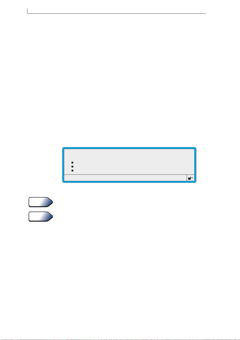
Chapter 4: Creating and Editing Messages
4.1.3 Choosing the Message Type
The message type you choose determines the height of the message in
numbers of drops. This can be from five drops high up to 16 drops high. It
also dictates the maximum character size you can use. See ‘Selecting the
Size’ on page 51 for further information.
There are several message types to cater for different speeds of operation,
these are: Flexible, Quality, Speed, and Wide. When selecting message
types, refer to Appendix C to identify which message types meet the
maximum line speed of your operation; Quality message types are
generally used for low speeds, Flexible for low to medium speeds, Speed
for high speeds, and Wide for very high speed requirements. Note that
Flexible message types have a greater print height adjustment range.
The range of message types available varies according to the printer
configuration and printhead type in use.
You use the MESSAGE TYPE menu to specify the message type. The
example below shows a sample of message types available for the Ultima
printhead with a 2-line, Standard Speed (SS) configuration:
MESSAGE TYPE
>
7 Quality
7 Flexible
16 Quality
16 Flexible
49189
Figure 4-2 Example Message Types
Tip
See Also
You can view the range of message types available on your printer via the
Diagnostics > System Co nfiguration > Message Type menu.
Full listings of message types for the Ultima and Ultima plus printheads
are provided in Appendix A, ‘Installation and Setup’.
Linx 4900 Operating Manual 50 MP65492–1
Page 70
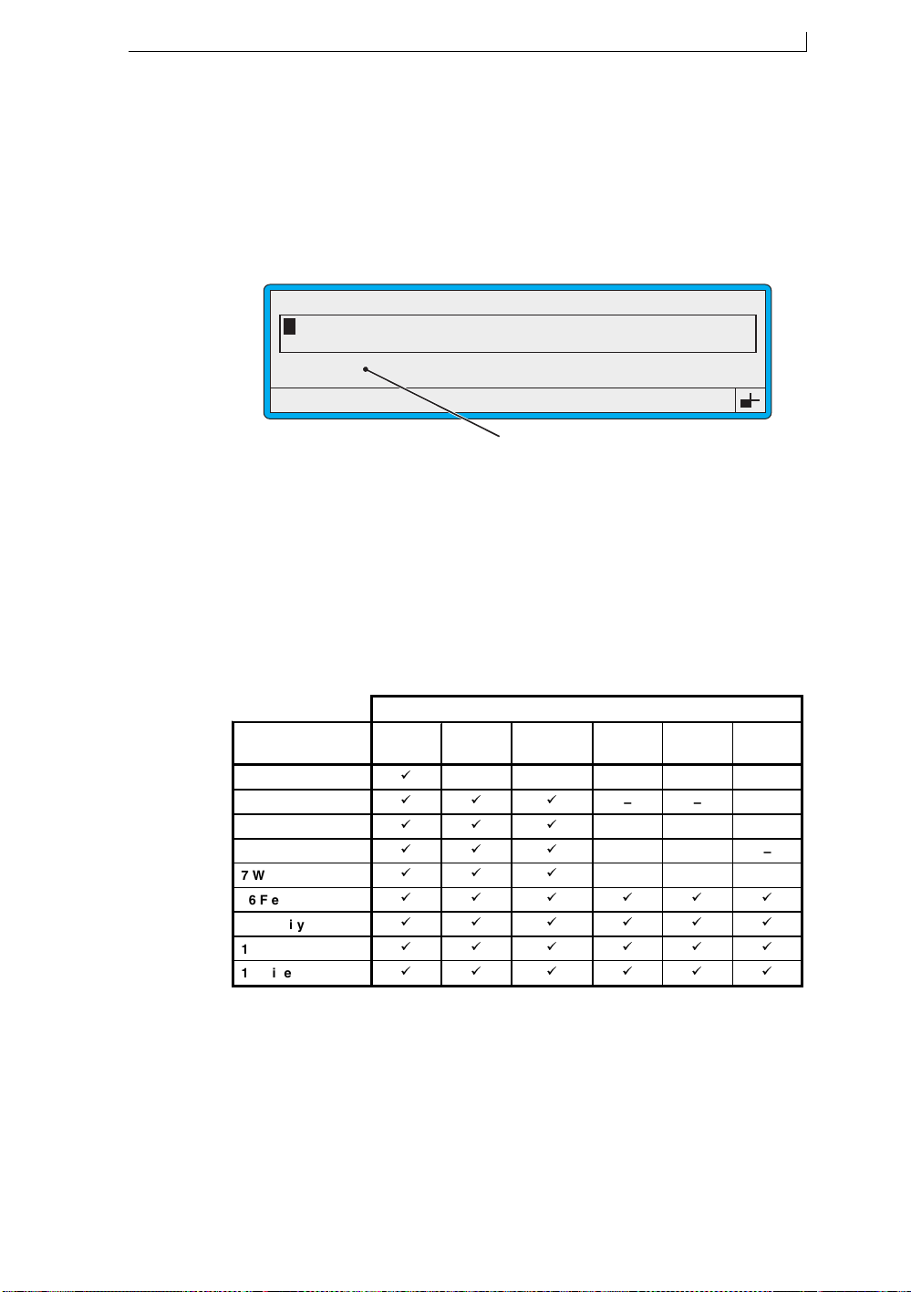
Chapter 4: Creating and Editing Messages
4.1.4 Selecting the Size
When you select the size, you choose the character set for the message
field. This determines the size of the characters, which in turn dictates the
height of the message field.
You use the F1 : Size option at the EDIT MESSAGE screen to select the
character set:
EDIT MESSAGE : MESSAGE 1
49113
F1 : Size 7 FH (Caps)
F3 : Field Type
F2 : Bold Off
F4 : Save & Exit
Selecting the Character Set
Figure 4-3 Selecting the Character Set
Character Set Availability
The range of character sets available is determined by the message type
selected. For example, using a 16-drop high message type, the character
size is limited to 16 or less (for a free format message), and for a 2-line
message, the maximum size is 7.
The following table shows which character sets are available for each
message type:
Message Types 5 FH
5 Wide
7 Flexible
7 Quality
7 Speed
7 Wide
16 Flexible
16 Quality
16 Speed
16 Wide
(Caps)
7 FH
(Caps)
CHARACTER SETS
7 Arab
Num
– – – – –
16 FH
(Caps)
16 non-
FH
– – –
– – –
– – –
– – –
49079
16 Arab
Num
Figure 4-4 Character Sets
Note that the numerical value in the name of each message type and
character set indicates the height of the printed character, in drops.
MP65492–1 51 Linx 4900 Operating Manual
Page 71
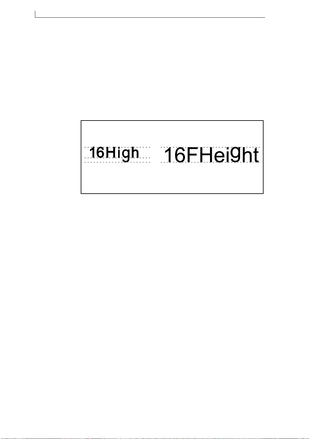
Chapter 4: Creating and Editing Messages
Choosing the Character Set
Character sets are available in either ‘FH (Caps)’ (Full Height characters),
or ‘non-FH’, and have a complete set of upper-case and lower-case
characters. However, they differ in the way that characters with
‘descenders’ are handled.
The example below shows how non-FH characters have an invisible
margin to cater for descenders, whereas FH (Caps) characters have the
same baseline as the upper-case characters; useful for printing capital
letters.
49128
Non-FH
Note descenders
under the baseline
Figure 4-5 Full Height and Non-Full Height Characters
Letters with descenders are
raised to sit on the baseline.
FH (Caps)
4.1.5 Using a Bold Ratio
You can set up a bold ratio (from x2 to x10), then apply it to any new
message field to make the printed characters appear heavier.
As an example, a 7 High character is created with a matrix of 7x5 when the
bold factor is set to x1 (standard print). With a bold factor of x2, the same
character is formed on a matrix of 7x10, making it the same height but
twice as wide.
You use the following settings to define and to apply a bold ratio:
• Use the Bold Ratio setting in the SETUP menu to define the ratio
• Use the F2 : Bold option on the EDIT M ESSAGE screen to apply the
defined bol d ratio to a particular new message field
NOTE: The bold ratio can only be applied to a new field, not an existing
field.
Linx 4900 Operating Manual 52 MP65492–1
Page 72

Chapter 4: Creating and Editing Messages
4.1.6 Reversing the Printed Message
You can change the orientation of the printed message from the normal
forward orientation:
49275
to reverse orientation, where the message is printed right to left:
49276
Use the Reverse Message option in the SETUP menu to switch the setting
On or Off.
MP65492–1 53 Linx 4900 Operating Manual
Page 73
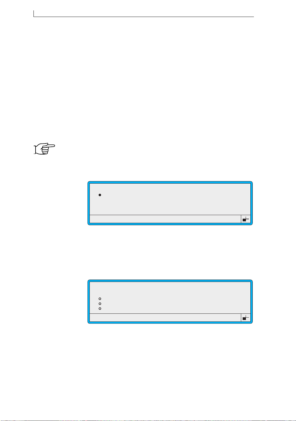
Chapter 4: Creating and Editing Messages
4.2 Creating a New Message
Note that printing must be stopped. If necessary, press the [F1] function
key to stop printing.
To create a new message, do the following:
• Name the message, using the NEW MESSAGE screen
• Select the message type, using the MESSAGE TY PE menu
• Add text and/or other types of fields using the EDIT MESSAGE
screen
4.2.1 To Name the Message and Select the Message Type
1. At the CURRENT MESSAGE screen, press the [F3] function key.
NOTE: If the Password system is switched On, the PASSWORD screen
is displayed at this point and you must enter a password to
continue.
The NEW MESSAGE screen is displayed:
Enter Name > _
49019
NEW MESSAGE
Figure 4-6 New Message Screen
2. At the NEW MESSAGE screen, type in the message name, for
example, MESSAGE 1, then press the [enter] key. Note that you can
enter up to 15 characters.
The MESSAGE TYPE menu is displayed:
49013
MESSAGE TYPE
>
7 Quality
7 Flexible
16 Quality
16 Flexible
Figure 4-7 Message Type Menu
3. At the MESSAGE TYPE menu, scroll through the list of available
message types until the cursor rests at the message type yo u want, then
press [enter] key.
Linx 4900 Operating Manual 54 MP65492–1
Page 74
Chapter 4: Creating and Editing Messages
See Also
Refer to the section ‘Choosing the Message Type’ on page 50 for
further information about message types.
The EDIT MESSAGE screen is displayed:
49118
EDIT MESSAGE : MESSAGE 1
F1 : Size 7 FH (Caps)
F3 : Field Type
F2 : Bold Off
F4 : Save & Exit
Figure 4-8 Edit Message Screen: New Message
4. You can now create the content of y our mes s age by adding text and/or
other types of fields and then save the message. See the following
sections in this chapter for details.
MP65492–1 55 Linx 4900 Operating Manual
Page 75
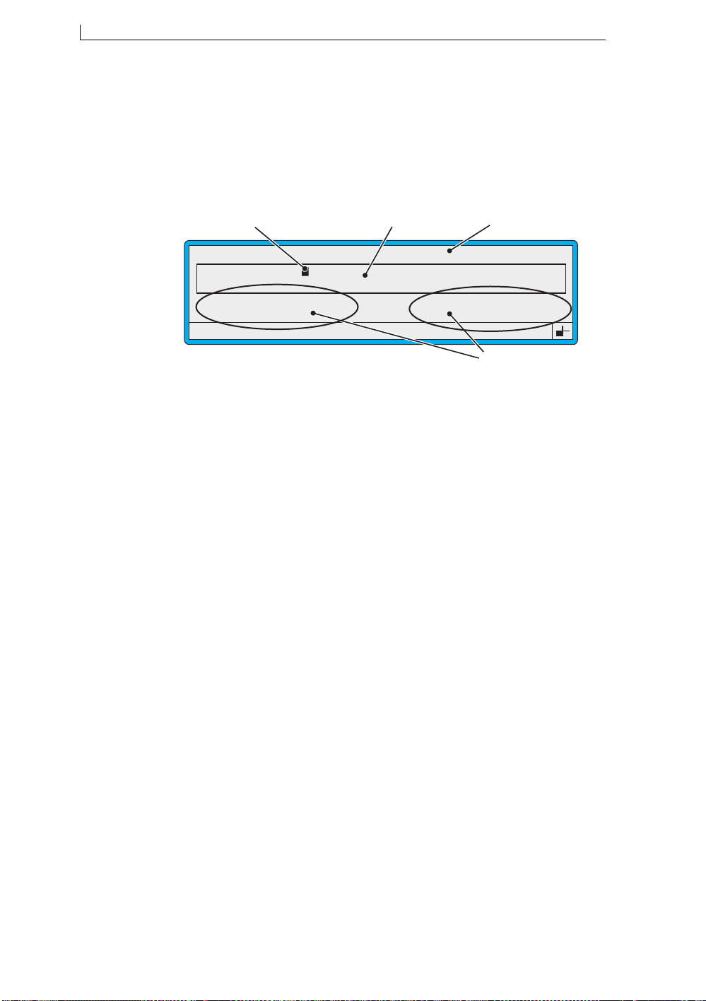
Chapter 4: Creating and Editing Messages
4.3 Getting to Know the EDIT MESSAGE Screen
You use the EDIT MESSAGE screen to create and edit all types of
messages. The following example shows you the main features and
indicators:
A
EDIT MESSAGE : MESSAGE 1
Sell by
B
C
49117
LINX
F1 : Size 7 FH (Caps)
F3 : Field Type
Feature/indicator... Description...
A
B Message Display Area Area where the message being created or
C Message Name The name of the message being created or
D
Message Cursor
Options
Shows current cursor position. See the
Message Cursor ‘About’ box below.
edited is displayed, and where you work on
the message.
edited.
Allow you to perform message editing
functions by pressing the associated
function key:
Press [F1] to select the character size.
F2 : Bold Off
F4 : Save & Exit
D
Press [F2] to switch the bold ratio on or
off.
Press [F3] to specify the field (Time,
Timed Message, Sequential Number, Date,
Remote or Logo field).
Press [F4] to save the message and exit
from the screen, back to the CURRENT
MESSAGE screen.
Figure 4-9 Edit Message Screen Features and Indicators
Linx 4900 Operating Manual 56 MP65492–1
Page 76
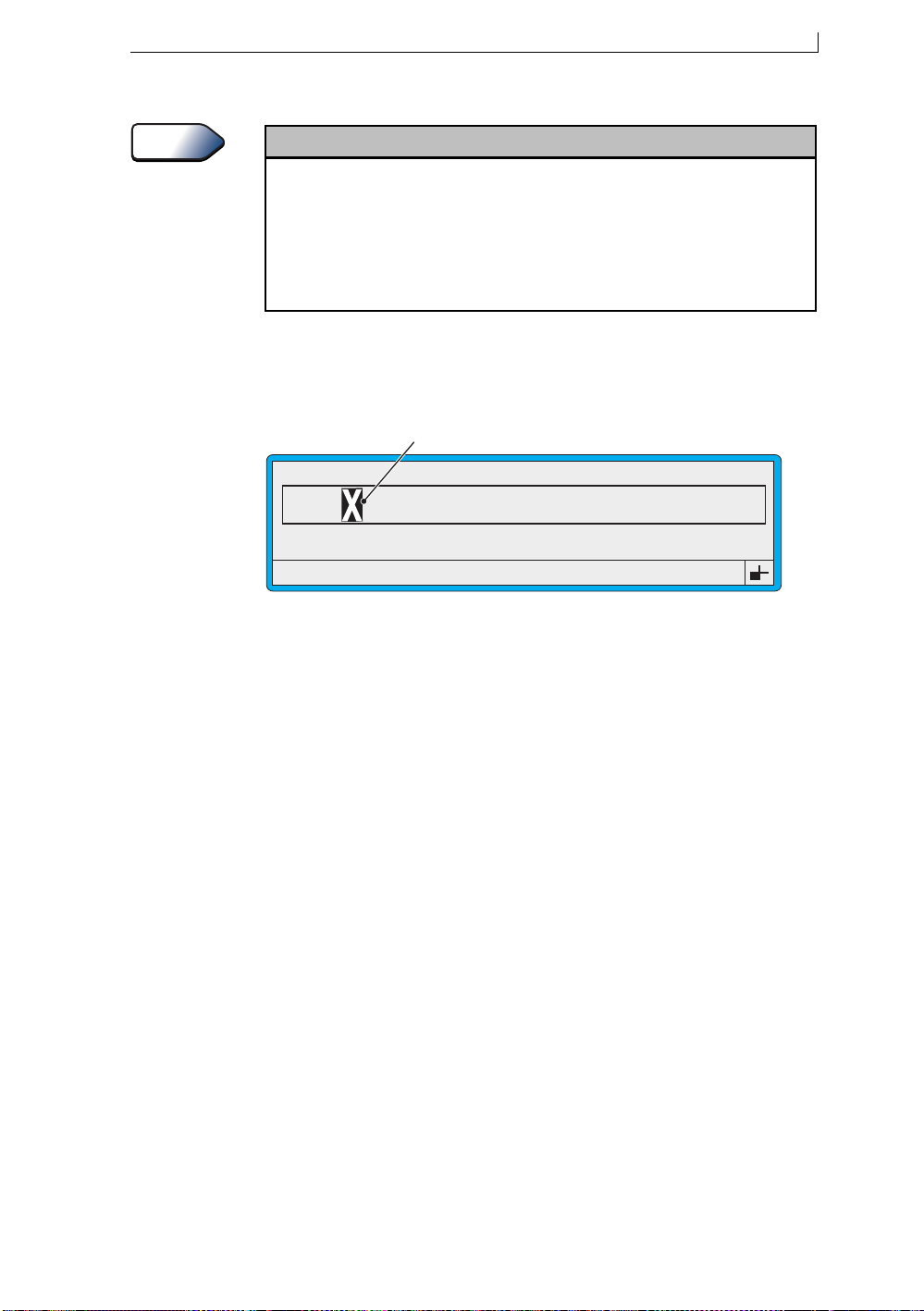
Chapter 4: Creating and Editing Messages
About
Message Cursor
The Message Cursor shows the current position of the cursor in the Message Display Area of
the Edit Message screen. The size of the message cursor changes according to the character
size of the last selected field.
When
creating
new field. This position must be unoccupied by any other field.
When
action of the character it occupies between normal and reverse display.
a field in a message, you move the message cursor to the start position of the
editing
a field, the position of the message cursor in the field is shown by the flashing
The following illustration shows how the position of the message cursor
within a field is indicated by the flashing action of the character it
occupies:
Cursor position
EDIT MESSAGE : MESSAGE 1
49127
LIN
F1 : Size 16 FH (Caps)
F3 : Field Type
Figure 4-10 Message Cursor Position
F2 : Bold Off
F4 : Save & Exit
MP65492–1 57 Linx 4900 Operating Manual
Page 77
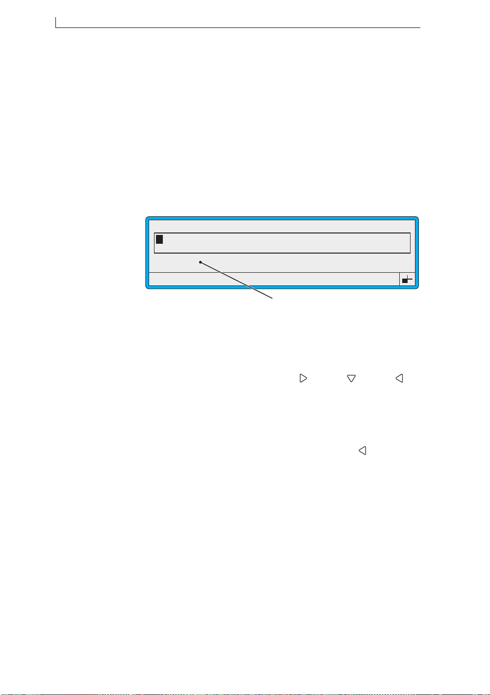
Chapter 4: Creating and Editing Messages
4.4 Creating a Text Field
You create a text field using the EDIT MESSAGE screen as follows:
• Select the character size using the Size option
• Add text by typing it using the keyboard
• Turn the text into a field
You can also apply the bold ratio by using the Bold option.
4.4.1 To Select the Character Size
1. Press the [F1] key to step through the available character sets until the
character size you want is displayed:
EDIT MESSAGE : MESSAGE 1
49113
F1 : Size 7 FH (Caps)
F3 : Field Type
Selecting the Character Set
Figure 4-11 Selecting the Character Set
F2 : Bold Off
F4 : Save & Exit
4.4.2 To Add Text
1. In the Message Display Area of the EDIT MESSAGE screen,
position the cursor where you want the field to start. If necessary,
move the cursor by pressin g the Right [ ], Down [ ] or Left [ ]
arrow keys.
2. Type in the text using the keyboard.
As you enter the text, you can press the [del] key to delete the
character to the left of the cursor.
NOTE: Take care not to press the [enter] key, or the Left [ ] arrow key
(in an attempt to step back through the characters) before you
have finished entering the text. If you do this, the text
immediately turns into a field and if you attempt to continue
entering text, the message “Overlap: Press Enter to Edit” is
displayed in the Status Line. See ‘Handling a Field Overlap
Message’ on page 63 for further information.
Linx 4900 Operating Manual 58 MP65492–1
Page 78

Chapter 4: Creating and Editing Messages
4.4.3 To Turn the Text into a Field
1. When you have finished entering the text, press the [e nter] k e y to t ur n
the text into a field.
This action fixes the field length and the number of characters.
NOTES:
1. Moving the cursor with the Le ft [ ] or the Right [ ] arrow keys,
or pressing the [enter] key or the [F1] key al so turns the text into a
field.
2. As you are entering text, if the message “Overlap: Press Enter to
Edit” is displayed in the Status Line, this means you have
unintentionally turned the text into a field. The field length is now
fixed so you cannot continue adding characters to the field.
If you want to add characters to the field, delete the field and start
entering text again. See ‘To Delete a Field’ on page 63 for details.
If you want to change the text, edit the field. See ‘To Edit a Text
Field’ on page 62 for details.
4.4.4 Saving the Message
When you have finished creating the message:
1. Press the [F4] function key to save the message and exit. Alternatively ,
press the [esc] key.
MP65492–1 59 Linx 4900 Operating Manual
Page 79

Chapter 4: Creating and Editing Messages
4.5 Working with Message Fields
This section describes how to work with message fields as you create and
edit a message in the Message Display Area of the EDIT MESSAGE
screen.
4.5.1 Navigating the Message Display Area
As you work with a message, you can use the following keystrokes:
Press... To move the message cursor...
[shift] + [ ], [ ], [ ] or [ ]
[] []
[] []
[ctrl] +[ ], [ ], [ ] or [ ]
Press...
[del] To delete the character to the left of the
[enter] To turn the text into a field (when you
[ctrl] + [del] Delete a field from the message.
To the start, end, top or bottom of the
message.
Right or left by one character (width).
Up or down by one character (height).
Up, down, left or right (by one drop).
To do this...
cursor (as you enter text).
have finished entering text).
To select a field (with cursor at field).
Linx 4900 Operating Manual 60 MP65492–1
Page 80
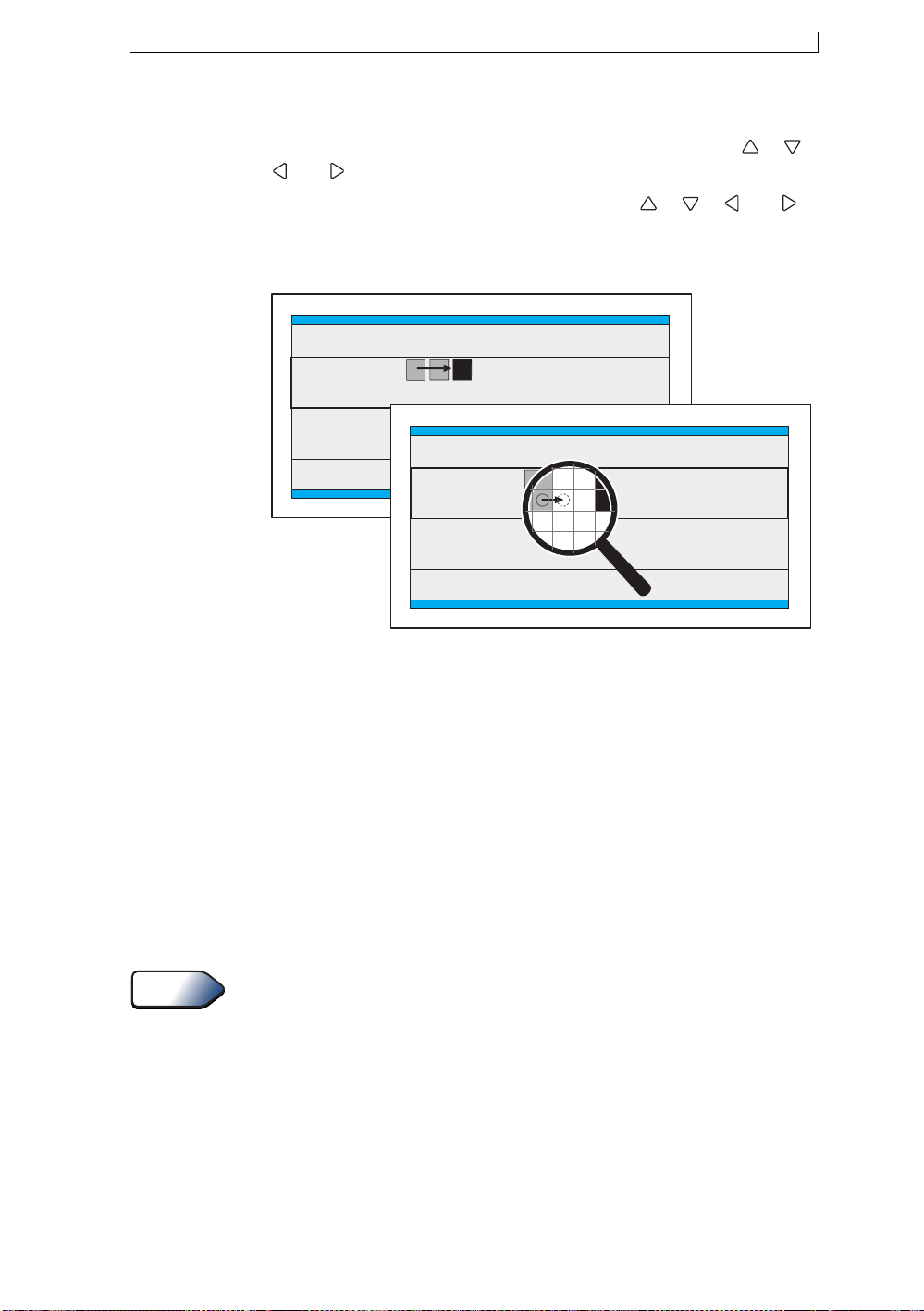
Chapter 4: Creating and Editing Messages
4.5.2 Fine Tuning the Field Start Position
T o positio n the cursor where you want the field to start, use the [ ], [ ],
[ ] or [ ] arrow keys (see Example A in Figure 4-12 below).
By pressing the [ctrl] key in conjunction with the [ ], [ ], [ ] or [ ]
arrow keys, you can move the cursor just one drop at a time (see Example
B in Figure 4-12 below):
49291
Example A
SSAGE : MESSAGE 1
LINX
Message
ssage
Example B
F2 : Check Status
F4 : Change Setu
SSAGE : MESSAGE 1
LINX
Message
ssage
Figure 4-12 Positioning the Message Cursor
4.5.3 Applying Bold to a Field
You can switch the Bold option to On to apply bold to a message field as
you create it; this makes the printed characters appear heavier.
The ratio of bold applied to the field is determined by the Bold Ratio value
defined in the SETUP menu. See also ‘Defining the Bold Ratio’ on
page 99.
To apply the defined bold ratio to a field:
1. At the EDIT MESSAGE screen, press the [F2] function key to toggle
the Bold setting to On.
2. Continue creating the field as required.
F2 : Check Status
F4 : Change Setu
Tip
MP65492–1 61 Linx 4900 Operating Manual
For multiple field messages, create the emboldened field before you create
the other fields in the message because once a bold ratio is applied to the
field, the width of the field increases.
Page 81

Chapter 4: Creating and Editing Messages
4.5.4 Entering Text
Type in the text using the keyboard then press the [enter] key to turn the
text into a field.
As you enter the text, you can press the [del] key to delete the character to
the left of the cursor.
Tip
To type lower-case characters, press and hold the [shift] key. For further
information about typing keyboard characters, see ‘Typing Keyboard
Characters’ on page 20.
NOTE: If you press the [enter] key, or the Left [ ] arrow key (in an
attempt to step back through the characters), or the [F1] key,
before you have finished typing, the text immediately turns into a
field. If you then attempt to continue entering text, the message
“Overlap: Press Enter to Edit” is displayed on the S tatus Line. See
‘Handling a Field Overlap Message’ on page 63 for further
information.
4.5.5 To Select a Field for Editing
1. In the Message Display Area, press the Left [ ] arrow and Right [ ]
arrow keys to move the cursor to any character within the field you
wish to edit.
2. Press the [enter] key.
4.5.6 To Edit a Text Field
1. Select the field for editing. To do this, move the cursor to any
character within the field, then press the [enter] key.
The field is highlighted and the cursor position is shown by the
flashing action of the character it occupies, see Figure 4-10 on
page 57.
2. Press the Left [ ] arrow or Right [ ] arrow key to move to the
character you wish to change, then overtype.
NOTES:
1. You cannot delete characters, or add characters to extend a field.
If you wish to do this, you m ust delete the wh ole field (see ‘To
Delete a Field’ on page 63) and start entering text again.
2. Avoid typing in excess characters as this results in text
‘wraparound’. For example, typing ‘ABCD’ in a field which
reads ‘ABC’ results in overwriting the ‘A’, thus the field would
read ‘DBC’.
3. See also NOTE under ‘Entering Text’.
Linx 4900 Operating Manual 62 MP65492–1
Page 82

Chapter 4: Creating and Editing Messages
4.5.7 To Edit a Field
T o edit any field type (except a text field, see ‘To Edit a Text Field’ above),
that is, a date, time, timed message, sequential number, remote or a logo
field, do the following:
1. Select the field for editing. To do this, move the cursor to any
character within the field, then press the [enter] key.
2. The associated menu is displayed. For example, if you select a time
field, the TIME menu is displayed.
3. Make the necessary changes as required, then press the [esc] key to
return to the EDIT MESSAGE screen.
NOTES
1. You cannot move a field. If you wish to do this, you must delete
the whole field (see ‘To Delete a Field’ below) and recreate it in
the new position.
2. Editing option values: make sure you press the [enter] key to
complete your entry and save the change before you press the
[esc] key to exit.
3. Editing a timed message field: you can change the existing
messages (Time and Message text), however, you cannot add
new timed messages. If you wish to add an other timed message to
the field you must delete the field and start again. To do this, at
the EDIT MESSAGE screen select the field and press [ctrl] +
[del].
4.5.8 To Delete a Field
All field types are deleted using the same method:
1. Move the message cursor to the field you wish to delete.
2. Press the [ctrl] and [del] keys together.
The field is removed from the message.
4.5.9 Handling a Field Overlap Message
At the EDIT MESSAGE screen, if the message “Overlap: Press Enter to
Edit” is displayed on the Status Line, this means one of the following
things:
• If you are entering text, you have unintentionally turned the text into a
field. This fixes the field length so you cannot continue adding
characters to the field. If necessary, delete the field and start entering
text again
• Y ou have pressed the [enter] k ey in an attempt to go back and correct a
character in the field. Press the [enter] key again to turn the text into a
field then edit it. See ‘To Edit a Text Field’ on page62
• If you are creating a new field, the cursor is in a position that is already
occupied by another field. Move the cursor to a free space and start
again
MP65492–1 63 Linx 4900 Operating Manual
Page 83
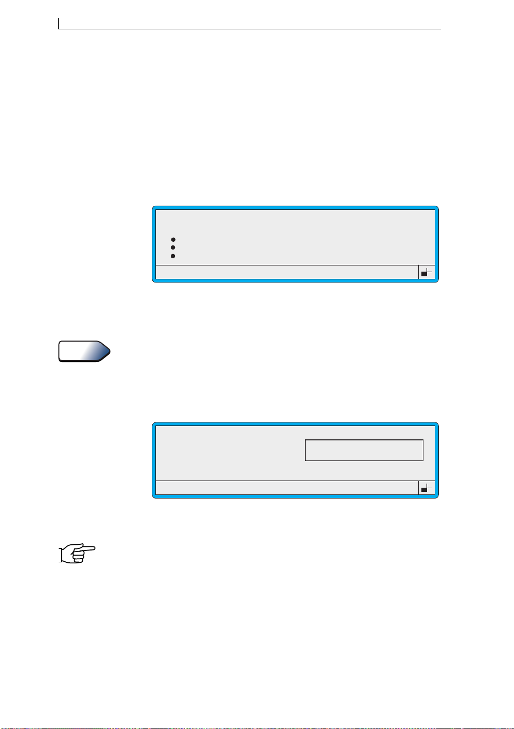
Chapter 4: Creating and Editing Messages
4.6 Selecting, Editing and Deleting Messages
4.6.1 To Select a Message for Editing
Note that printing must be stopped. If necessary, press the [F1] function
key to stop printing.
1. At the CURRENT MESSAGE screen, press the [F1] function key.
The SELECT MESSAGE menu is displayed:
MESSAGE 1
>
MESSAGE 2
MESSAGE 3
MESSAGE 4
Figure 4-13 Select Message Menu
2. At the SELECT MESSAGE menu, scroll through the list until the
cursor rests at the message you want to edit.
Tip
Type in the first letter of the message name to quickly find the
message you want. Note that the letter you enter is case sensitive.
3. Press the [enter] key.
The MESSAGE OPTIONS screen is displayed, sho wing a preview of
the message:
MESSAGE OPTIONS : MESSAGE 1
F1 : Edit
F2 : Select
F3 : Delete
49014
SELECT MESSAGE
49016
LINX PRINT
Figure 4-14 Message Options Screen
4. At the MESSAGE OPTIONS screen, press the [F1] function key.
NOTE: If the Password system is switched On, the PASSWORD screen
is displayed at this point and you must enter a password to
continue.
Linx 4900 Operating Manual 64 MP65492–1
Page 84
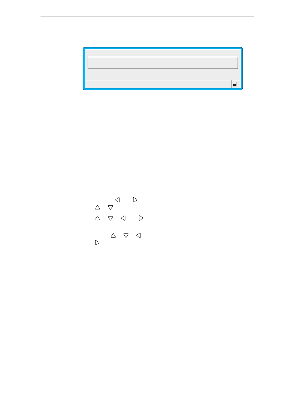
Chapter 4: Creating and Editing Messages
The EDIT MESSAGE screen is displayed:
EDIT MESSAGE : MESSAGE 1
LINX PRINTING
F1 : Size 16 FH (Caps)
F3 : Field Type
Figure 4-15 Edit Message Screen
4.6.2 To Edit a Message
Note that printing must be stopped. If necessary, press the [F1] function
key to stop printing.
1. Select the message for editing. Refer to ‘To Select a Message for
Editing’ on page 64 for details.
2. With the selected message displayed in the Message Display Area of
the EDIT MESSAGE screen, edit the message by selecting each field
in turn and making the required changes:
Press this key... To...
F2 : Bold Off
F4 : Save & Exit
49030
[enter] Select a field for editing.
[shift] + [ ] or [ ],
[], []
[ ], [ ], [ ] or [ ]
[ctrl] +[ ], [ ], [ ] or
[]
[F1] Change the character size.
[F2] Switch the bold factor on/off.
[F3] Change the field type.
[F4] Save changes and exit.
[del] Delete the selected field.
The section in this chapter ‘Working with Message Fields’ on page 60
gives you detailed instructions on how to select and edit all types of
fields.
3. When you have finished, press the [F4] function key to save the
changes and exit.
The CURRENT MESSAGE screen is redisplayed, showing the
edited message.
Move to the start, end, top or bottom of the
message.
Move the cursor up, down, left o r rig ht (by
one character).
Move the cursor up, down, left o r rig ht (by
one drop).
MP65492–1 65 Linx 4900 Operating Manual
Page 85
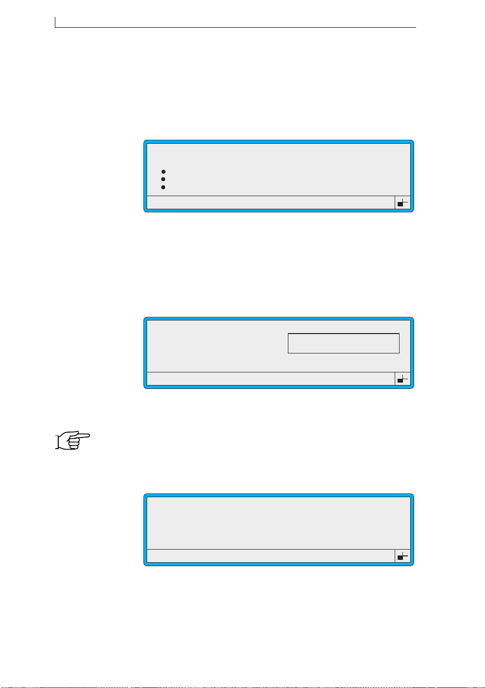
Chapter 4: Creating and Editing Messages
4.6.3 To Delete a Message
Note that printing must be stopped. If necessary, press the [F1] function
key to stop printing.
1. At the CURRENT MESSAGE screen, press the [F1] function key.
The SELECT MESSAGE menu is displayed:
MESSAGE 1
>
MESSAGE 2
MESSAGE 3
MESSAGE 4
Figure 4-16 Select Message Menu
2. At the SELECT MESSAGE menu, scroll through the list until the
cursor rests at the message you want.
3. Press the [enter] key.
The MESSAGE OPTIONS screen is displayed, sho wing a preview of
the message:
MESSAGE OPTIONS : MESSAGE 1
F1 : Edit
F2 : Select
F3 : Delete
49014
SELECT MESSAGE
49016
LINX PRINT
Figure 4-17 Message Options Screen
4. At the MESSAGE OPTIONS screen, press the [F3] function key.
NOTE: If the Password system is switched On, the PASSWORD screen
is displayed at this point and you must enter a password to
continue.
The DELETE MESSAGE screen is displayed:
49129
DELETE MESSAGE
Delete Message : MESSAGE 1
F1 : Yes
F2 : No
Figure 4-18 Delete Message Screen
Linx 4900 Operating Manual 66 MP65492–1
Page 86

Chapter 4: Creating and Editing Messages
5. Press the [F1] function key to select Yes. The message is deleted and
the CURRENT MESSAGE screen is redisplayed. Note that the
Message Display Area is blank (no message is selected).
OR
Press the [F2] function key to select No. The message is not deleted
and the CURRENT MESSAGE screen is redisplayed showing the
selected message.
4.6.4 To Delete the Current Message
To delete the message displayed on the CURRENT MESSAGE screen:
1. Press the [del] key.
The DELETE MESSAGE screen is displayed (see Figure 4-18 on
page 66).
2. Press the [F1] function key to select Yes. The message is deleted and
the CURRENT MESSAGE screen is redisplayed. Note that the
Message Display Area is blank (no message is selected).
OR
Press the [F2] function key to select No. The message is not deleted
and the CURRENT MESSAGE screen is redisplayed showing the
selected message
MP65492–1 67 Linx 4900 Operating Manual
Page 87
Chapter 4: Creating and Editing Messages
4.7 Creating a Time Field
The current time can be added to a message by creating a time field.
NOTE: The current time (system time) is set using the Set Time option in
the SETUP menu.
The TIME menu allows you can choose from the following time formats:
Format Usage / Example
hh:mm 24 hr clock / 16:35
hh:mmpm 12 hr clock / 04:35pm
hhmm 24 hr clock / 1635
hhmmpm 12 hr clock / 0435pm
hh (24h) 24 hr clock, 00 through 23
hh (12h) 12 hr clock, 01 through 12
mm minutes, 00 through 59
Figure 4-19 Time Formats
49125
TIME FORMATS
4.7.1 To Create a Time Field
1. In the Message Display Area of the EDIT MESSAGE screen, move
the cursor to the required start position of the field.
2. Press the [F3] function key. The SELECT FIELD TYPE menu is
displayed:
SELECT FIELD TYPE
>
Time
Timed Message
Sequential No.
Date
Figure 4-20 Select Field Type Menu: Time Option
3. Scroll to the Time option (as shown in the abov e examp l e), th en pr ess
the [enter] key.
49308
Linx 4900 Operating Manual 68 MP65492–1
Page 88
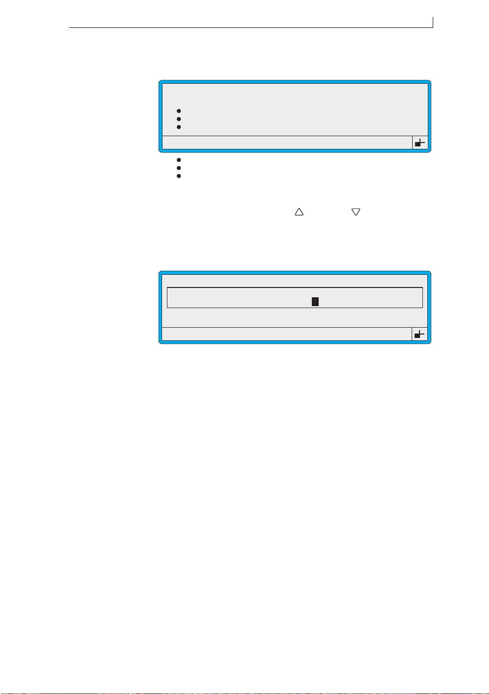
Chapter 4: Creating and Editing Messages
The TIME menu is displayed.
49309
TIME
>
hh:mm
hh:mmpm
hhmm
hhmmpm
hh (24h)
hh (12h)
mm
Figure 4-21 Time Menu
4. At the TIME menu, press the Up [ ] or Down [ ] arrow key to
scroll to the format you want.
5. Press the [enter] key to select the format and return to the EDIT
MESSAGE screen:
49119
EDIT MESSAGE : MESSAGE 1
Sell by dd mmm yy
LINX
F1 : Size 7 FH (Caps)
F3 : Field Type
BATCH 9999
hh:mm
F2 : Bold Off
F4 : Save & Exit
Figure 4-22 Edit Message Screen: Time Field
NOTE: The current time is not displayed in the message un til you
have finished editing the message and returned to the
CURRENT MESSAGE screen.
MP65492–1 69 Linx 4900 Operating Manual
Page 89
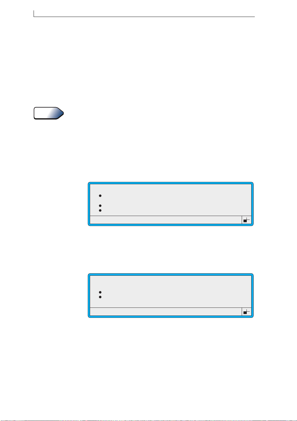
Chapter 4: Creating and Editing Messages
4.8 Creating a Timed Message Field
Creating a timed message field allows you to set up two or more text
messages that print in turn according to the specified start time.
For each timed message field you create, up to 24 text messages can b e set
up, each with a unique time at which the message appears within the
printed message.
See Also
To work through an example of setting up a timed message field
(containing two messages Day Shift and Night Shift), refer to ‘To Insert a
Timed Message’ on page 89.
4.8.1 To Create a Timed Message Field
1. In the Message Display Area of the EDIT MESSAGE screen, move
the cursor to the required start position of the field.
2. Press the [F3] function key. The SELECT FIELD TYPE menu is
displayed:
SELECT FIELD TYPE
Time
>
Timed Message
Sequential No.
Date
Figure 4-23 Select Field Type Menu: Timed Message Option
3. Scroll to the Timed Message option (as shown in the above example),
then press the [enter] key.
The TIMED MESSAGE me nu is displayed.
TIMED MESSAGE
>
Next Message
Time
Message
:
:
49307
49130
Figure 4-24 Timed Message Menu
4. At the TIMED MESSAGE menu, you can do the following:
NOTE: You must set up a minimum of two messages, each with a
different start time.
Linx 4900 Operating Manual 70 MP65492–1
Page 90
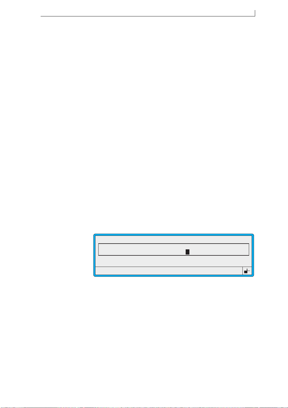
Chapter 4: Creating and Editing Messages
At this option... You can do this...
Next Message When creating a new field, press the [enter] key to
clear the screen ready to enter the first (or next)
timed message.
When editing an existing timed message field,
scroll through existing messages.
Time T ype in the time to start printing the message, in the
24 hour format, for example 18:00.
You must enter either a space, or any one of the
separators (/ . : : ,) between the hours and the
minutes.
Message Type in the message text, then press the [enter] key.
Always create the timed message with the longest
text first. The length of the first timed message sets
the maximum length of all subsequent messages
specified for the field.
Note that up to 10 characters are displayed as you
type in the text, however, you can enter up to 99
characters.
NOTE: Do not exit from the screen until all the messages are set up.
You cannot add messages to an existing timed message field.
5. When you have finished, press the [esc] key to save the messages and
return to the EDIT MESSAGE screen:
49120
EDIT MESSAGE : MESSAGE 1
Sell by dd mmm yy
LINX
F1 : Size 7 FH (Caps)
F3 : Field Type
BATCH 9999
Day Shift
F2 : Bold Off
F4 : Save & Exit
Figure 4-25 Edit Message Screen: Timed Message
Note that the last message created is displayed in the message area. At
the time of printing (at the CURRENT MESSAGE screen), the
appropriate message is displaye d.
4.8.2 Editing a Timed Message Field
When you edit a timed message field, you can change the existing
messages (Time and Message text), however, you cannot add new
messages.
If you wish to add another message to the field, you must delete the field
and start again. To delete the field, at the EDIT MESSAGE screen select
the field and press [ctrl] + [del].
MP65492–1 71 Linx 4900 Operating Manual
Page 91
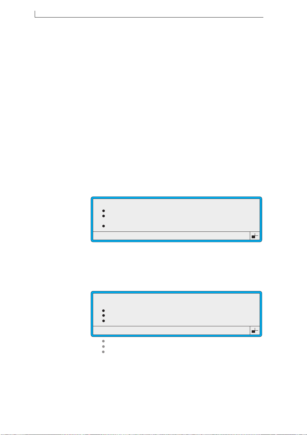
Chapter 4: Creating and Editing Messages
4.9 Creating a Sequential Number Field
A sequential number field is useful for incrementing (and decrementing)
numbers such as batch numbers and item counts.
You specify a range of numbers, or letters, or a combination of both.
Printing is controlled by the Print Trigger option setting in the SETUP
menu.
Before You Start
You may wish to precede the sequential number field with text, for
example, ‘BATCH’. If this is the case, you can refer to the worked example
‘To Insert a Batch Number’ on page 87 for details.
To create a sequential number field:
1. In the Message Display Area of the EDIT MESSAGE screen,
position the cursor at the required start position of the field.
2. Press the [F3] function key. The SELECT FIELD TYPE menu is
displayed:
SELECT FIELD TYPE
Time
Timed Message
>
Sequential No.
Date
49305
Figure 4-26 Select Field Type Menu: Sequential No. Option
3. Scroll to the Sequential No. option (as shown in Figure 4-26 above),
then press the [enter] key.
The SEQUENTIAL NUMBER menu is displayed:
49123
SEQUENTIAL NUMBER
>
Reset Number
Current Number
Start Number
End Number
Interval
No of Repeats
Repeat Count
:
:
:
: 1
: 1
: 0
Figure 4-27 Sequential Number Menu
Linx 4900 Operating Manual 72 MP65492–1
Page 92
Chapter 4: Creating and Editing Messages
4. At the SEQUENTIAL NUMBER menu, you can do the following:
At this option... You can...
Reset Number Press the [enter] key to reset the Current Number
to the value of the Start Number, and to set the
Repeat Count value to zero.
Current Number View the current number.
Start Number Enter the value of the fir st number in the range, for
example, 0000. See the Sequential Number Values
‘About’ box below.
End Number Confirm the last number in the range.
Enter the last number in the range, for example,
9999. Overtype the number displayed as required.
For a decrementing number , enter a value less than
the Start Number value.
Interval Enter the value by which to increment or
decrement. For example, with a start number of
000, an interval value of 2 increments as 002, 004,
006, and so on, and -2 decrements as 999, 997,
995, and so on. The i nterval value defaults to 1 an d
the range is 1 through 127.
No of Repeats Enter the number of times the sequential number is
printed before the next increment. This value
defaults to 1.
Repeat Count Displays the number of times the sequential
number has printed with the Current Number
value. Maximum value is No of Repeats value
minus 1.
This value defaults to 0.
Start Number, End Number and Current Number
Up to 10 alphanumeric characters can be included in a sequential number, in the format 0–9,
a–z, A–Z. For example, Start Number 000 End Number 999. Each position can contain a
character from one of these formats, for example, Start Number 00a00A End Number
99z99Z.
Use any other characters as non-incrementing characters, for example, ‘.’ or ‘/’. These must
be entered at the same position in both the Start Number and End Number option values, for
example, Start Number 000/000A End Number 999/999Z.
Sequential Number Values
MP65492–1 73 Linx 4900 Operating Manual
Page 93
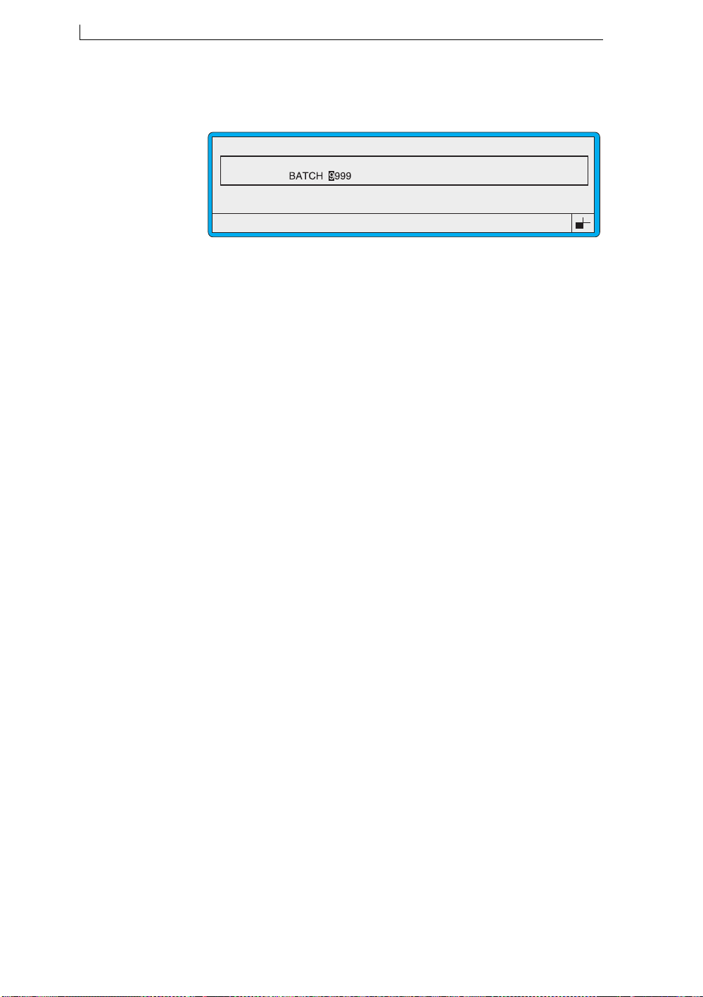
Chapter 4: Creating and Editing Messages
5. When you have finished, press the [esc] key to save the information
and return to the EDIT MESSAGE screen, for example:
EDIT MESSAGE : MESSAGE 1
Sell by dd mmm yy
LINX
F1 : Size 7 FH (Caps)
F3 : Field Type
Figure 4-28 Edit Message Screen: Sequential Number
49115
F2 : Bold Off
F4 : Save & Exit
Linx 4900 Operating Manual 74 MP65492–1
Page 94
Chapter 4: Creating and Editing Messages
4.10 Creating a Date Field
You can create a date field for sell-by dates , use-by dates, o r any othe r date
related information.
The DATE FORMAT menu allows you to choose from the f ollowi ng date
formats:
DATE FORMATS
Format Usage / Example
dd mmm yy 23 JUN 04
dd mmm yyyy 23 JUN 2004
mmm dd yy JUN 23 04
mmm dd yyyy JUN 23 2004
mmm month, Jan, Feb, Mar, etc.
dd mmm 23 JUN
dd.mm.yy 23.06.04
mm/dd/yy 06/23/04
yy.mm.dd 04.06.23
d day of week, 0 through 6 (Sun–Sat)
d (1-7) day of week, 1 through 7 (Mon–Sun)
dd day of month, 1 through 31
jjj Julian date, 001 through 366. See Note 1.
ww week number, 1 though 52
mm month number, 1 through 12
y year of decade, 0 through 9
yy year of century, 00 through 99
yyyy full year, 2004
y jjj year of decade, Julian date (001 through 366). See Note 1.
yy–mm–dd a Arabic format, 4– 6–23. See Note 2.
Figure 4-29 Date Formats
49126
NOTES:
1. T o specify the Julian date fo rmat as either European or Americ an,
please refer to ‘To Specify the Julian Date Format’ on page 110.
2. The Arabic date format ‘yy-mm-dd a’ can be used with standard
fonts (for roman numerals), or with Arabic fonts (for Arabic
characters). When used with standard fonts, note the leading
spaces (4– 6–23).
The DATE menu allows you to specify the ‘offset’ number of days. This
period from the current date creates the actual printed date.
MP65492–1 75 Linx 4900 Operating Manual
Page 95
Chapter 4: Creating and Editing Messages
4.10.1 To Create a Date Field
1. In the Message Display Area of the EDIT MESSAGE screen, move
the cursor to the required start position of the field.
2. Press the [F3] function key. The SELECT FIELD TYPE menu is
displayed:
SELECT FIELD TYPE
Time
Timed Message
Sequential No.
>
Date
Figure 4-30 Select Field Type Menu: Date Option
3. Scroll to the Date option (as shown in Figure 4-30 above), then press
the [enter] key.
The DATE FORMAT menu is displayed:
>
dd mmm yy
dd mmm yyyy
mmm dd yy
mmm dd yyyy
49302
49011
DATE FORMAT
Figure 4-31 Date Format Menu
4. At the DATE FORMAT menu, scroll to the format you want, then
press the [enter] key to select it.
The DATE menu is displayed showing the date format selected:
49304
DATE
>
Offset
Format
: 0
: dd mmm yy
Figure 4-32 Date Menu
Linx 4900 Operating Manual 76 MP65492–1
Page 96
Chapter 4: Creating and Editing Messages
5. At the DATE menu, you can specify the offset as follows:
At this option... You can...
Offset Enter the number of days to be added to the
current date to create the printed date.
NOTE: Remember to press the [enter] key once
you have entered this value.
Format View the date format selected. This is display
only.
If you wish to change the f ormat displ ayed, pres s
[esc] to return to the DATE FORMAT menu and
select another format.
6. Once you press the [enter] key following your Offset value entry, the
EDIT MESSAGE screen is redisplayed, for example:
49112
EDIT MESSAGE : MESSAGE 1
Sell by dd mmm yy
LINX
F1 : Size 7 FH (Caps)
F3 : Field Type
F2 : Bold Off
F4 : Save & Exit
Figure 4-33 Edit Message Screen: Date Field
NOTE: The actual printed date is not displayed until you have
finished editing the message and returned to the CURRENT
MESSAGE screen.
MP65492–1 77 Linx 4900 Operating Manual
Page 97
Chapter 4: Creating and Editing Messages
4.11 Creating a Remote Field
A remote field reserves an area in a message (comprising a specified
number of characters) to which data can be downloaded from a remote
computer. You can create one or more remote fields, in which case
incoming data fills each field in the order in which the fields are created.
The 4900 printer has RS232 communications installed as standard,
however, data can only be received by the printer once it is connected to
the remote device using an RS232 interface cable, and the Remote
Interface settings have been configured. See Chapter 6, ‘Remote Interface
Setup’ for further details.
To create a remote field:
1. In the Message Display Area of the EDIT MESSAGE screen,
position the cursor at the required start position of the field.
2. Press the [F3] function key. The SELECT FIELD TYPE menu is
displayed:
SELECT FIELD TYPE
Timed Message
Sequential No.
Date
>
Remote
49310
Figure 4-34 Select Field Type: Remote
3. Scroll to the Remote option (as shown in Figure 4-34 above), then
press the [enter] key.
The REMOTE menu is displayed:
49311
REMOTE
>
Number of Characters : 9
Figure 4-35 Remote Menu
4. At the REMOTE menu, press the [enter] key to select the Number of
Characters option.
5. Type in the number of characters (up to a maximum of 255), then
press the [enter] key. This is the number of characters to be
downloaded into the field from a remote device.
Linx 4900 Operating Manual 78 MP65492–1
Page 98
Chapter 4: Creating and Editing Messages
6. Press the [enter] key to confirm your entry.
The EDIT MESSAGE screen is redisplayed showing the newly
created remote field:
EDIT MESSAGE : MESSAGE 1
Sell by dd mmm yy
LINX
F1 : Size 7 FH (Caps)
F3 : Field Type
BATCH 9999
*********
hh:mm Night Shift
F2 : Bold Off
F4 : Save & Exit
Figure 4-36 Edit Message Screen: Remote Field
Note that a remote field is indicated by a number of asterisks (*),
according to the number of characters specified when the field is
created. Once data is received, the asterisks are replaced by the
incoming data.
49121
MP65492–1 79 Linx 4900 Operating Manual
Page 99
Chapter 4: Creating and Editing Messages
4.12 Inserting a Logo Field
A set of Arabic logos are installed in your printer as standard. Additional
logos are only available if your printer software has been configured with
logos. For further information, contact your local Linx distributor.
Logos can then be used with any message by inserting a logo field.
To insert a logo field:
1. In the Message Display Area of the EDIT MESSAGE screen,
position the cursor at the required start position of the field.
NOTE: To maximize the space available for a logo within the
message and the range of logos available, ensure that the
cursor is positioned at the outside edge of the Message
Display Area. If the cursor is moved inside the perimeter of
the Message Display Area, the logos available will be limited
to those that fit within the area.
2. Press the [F3] function key. The SELECT FIELD TYPE menu is
displayed:
SELECT FIELD TYPE
>
Logo
Time
Timed Message
Sequential No.
49312
Figure 4-37 Select Field Type: Logo
3. Scroll to the Logo option (as shown in Figure 4-37 above), then press
the [enter] key.
The LOGO menu is displayed showing a list of available logos:
49313
LOGO
>
ArabE7
ArabP7
Exp. 7 (Arab)
Man. 7 (Arab)
Figure 4-38 Logo Menu
NOTE: Only logos that fit within the m essage you are creating or
editing are available (displayed). See Note at Step 1 above.
4. At the LOGO menu, scroll to the logo you want, then press the [enter]
key.
Linx 4900 Operating Manual 80 MP65492–1
Page 100
Chapter 4: Creating and Editing Messages
The EDIT MESSAGE screen is redisplayed showing the newly
created logo field, for example:
EDIT MESSAGE : MESSAGE 1
Sell by dd mmm yy
LINX
F1 : Size 7 FH (Caps)
F3 : Field Type
BATCH 9999
*********
hh:mm Night Shift
F2 : Bold Off
F4 : Save & Exit
Figure 4-39 Edit Message Screen: Logo Field
49122
MP65492–1 81 Linx 4900 Operating Manual
 Loading...