

Page 1
The LinPlug Reference Manual
All technical specifications of the product specified in this manual may be subject to change without notice.
The document may not be changed, especially copyright notices may not be removed or changed. LinPlug
and all LinPlug product names are trademarks of LinPlug Virtual Instruments GmbH. Mac and the Mac logo
are trademarks of Apple Computer, Inc., registered in the U.S. and other countries. The Built for Mac OS X
graphic is a trademark of Apple Computer, Inc., used under license. The Audio Units logo and the Audio
Units symbol are trademarks of Apple Computer, Inc. Microsoft® and Windows® are trademarks of Microsoft
Corporation, registered in the U.S. and other countries. All other trademarks are the property of their
respective owners.
Page 2

Welcome
Welcome
Thank-you for buying the LinPlug .
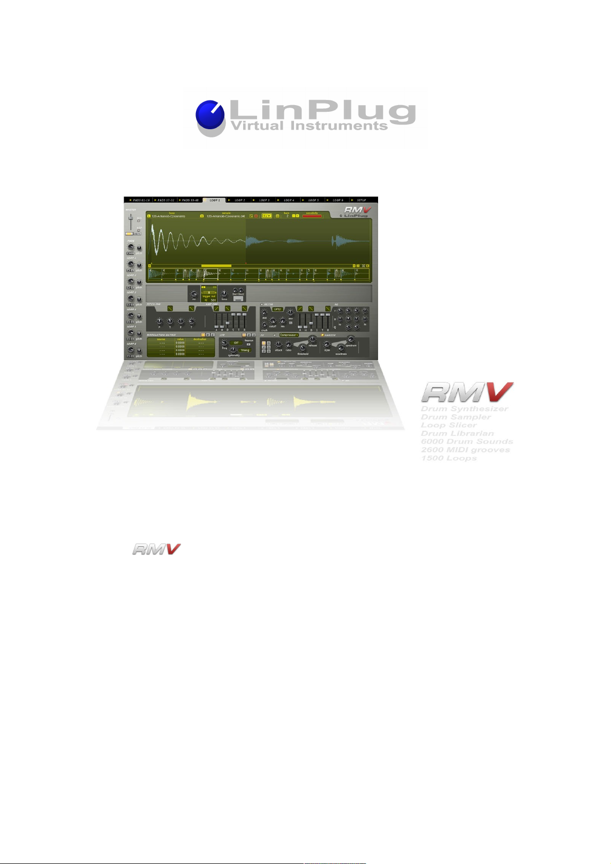
The RMV combines analog-style percussion synthesis, a fully-featured percussion
sampler, and a sophisticated Loop Editor/Player. The instrument combines all of the
features found on the LinPlug RM IV with several new and innovative features that
represent a substantial step forward.
The RMV contains forty-eight velocity-sensitive Pads, each which can be used to trigger
any one of a range of high quality Audio Modules (a selection of percussion synthesis
modules and a sophisticated percussion sampler module). Each Pad has its own
processing path containing an AHDSTR-controlled pitch envelope, three LFOs, an
AHDSTR-controlled multi-mode Filter and EQ, three Insert Effects (with nine Effect
options) and a “Varizer”. Each Pad also contains two distortion processors (Distortion and
BitCrusher). In addition to this, each Pad also features a twelve-by-twelve Modulation
Matrix, thirty-two-voice polyphony (selectable per Pad), as well as separate Volume,
Output, Tune, Pan, Choke, Mute and Solo controls.
The RMV introduces several new features including a sophisticated Loop Editor/Player, a
Send Effects section, several “Librarians” and an “intelligent” MIDI Mapper. The Loop
Editor/Player enables audio loops to be imported and then automatically “sliced” into
separate segments. Slice points can be adjusted manually if required. Six separate Loop
Editors/Players are available, each having its own dedicated processing path. The Send
Effects section contains 3 separate Effects Racks, each containing 4 Effects Units. The
first three Slots of each Effects Rack can be selected by the user, while the last Effects
Slot contains an EQ. The four Librarians feature detailed search and management tools for
Drum Kits, Pads, Loops and Grooves. Existing files can be imported and managed by the
RMV Librarian. The “intelligent” MIDI Mapper ensures that MIDI files are played back
correctly even when the Kit used to play them does not exactly match the contents of the
MIDI file being played. The MIDI Mapper automatically ensures that the closest matching
sound in the current Kit is used to play back the MIDI messages. For example, if a specific
HiHat sound is not present in the current Kit, the Mapper selects the next-best HiHat
sound from the current kit.
This guide describes all aspects of the RMV and is designed so that your use of this
software is as efficient and as pleasurable as possible.
We feel that the RMV is exceptional because of its audio quality, its wide range of features
and its sonic potential. We hope you get a lot of pleasure using the RMV and that it
becomes an important part of your music-making.
Peter Linsener and the LinPlug Team, July 2008
LinPlug Reference Manual 5.0.1 2
Page 3

Credits
Credits
Instrument Concept Peter Linsener Frank Neumann
Instrument Coding Peter Linsener Bartlomiej Bazior
Bo Johansen Pavol Markovic
DSP Code Peter Linsener Bo Johansen
Library Code Bartlomiej Bazior
GUI Design Branislav Pakic
Drumkits Redshift Audio Groove Criminals
Scott Solida Ken Fennel
Christian Bonifer Nico Herz
Paul Brown and others
MIDI Grooves Scott Solida Groove Monkee
and others
Audio Loops Frank Neumann Lambik
Marco Lehmann Steve Kay
and others
Manual Chris Share
Manual Translation to French Patrick Anglard
Manual Translation to Italian Mario Bianchi
Video Tutorials Frank Neumann
LinPlug Reference Manual 5.0.1 3
Page 4

Table of Contents
Table of Contents
Welcome................................................................................................................................2
Credits....................................................................................................................................3
Table of Contents...................................................................................................................4
Installation and Activation......................................................................................................9
Windows Installation..........................................................................................................9
OS X Installation..............................................................................................................10
Features...............................................................................................................................11
What's New in the RMV.......................................................................................................13
Overview..............................................................................................................................15
Controls................................................................................................................................17
Optimizing CPU Usage........................................................................................................18
Pads.....................................................................................................................................19
Pad Librarian....................................................................................................................25
Pad Information Display..............................................................................................26
Pad Search Input Display............................................................................................27
Search Results Display...............................................................................................30
Audio Modules.....................................................................................................................32
Percussion Synthesis Modules........................................................................................34
Kick 1...........................................................................................................................34
Kick 2...........................................................................................................................36
Snare 1........................................................................................................................38
Snare 2........................................................................................................................40
LinPlug Reference Manual 5.0.1 4
Page 5

Table of Contents
Tom..............................................................................................................................42
Open Hat/Closed Hat..................................................................................................44
Ride Cymb. (Cymbal)..................................................................................................46
Cymbal 2......................................................................................................................48
Claps............................................................................................................................49
Plop..............................................................................................................................51
Drum Synth..................................................................................................................53
Sampler Module...............................................................................................................56
Table View...................................................................................................................57
Waveform View............................................................................................................59
Pitch Envelope, Amplitude Envelope and Filter Envelope .........................................60
Sample Browser..........................................................................................................64
Loop Module........................................................................................................................67
Loop Section....................................................................................................................69
Waveform Section.......................................................................................................70
Slice Display................................................................................................................72
Pad Section......................................................................................................................73
Signal Path.......................................................................................................................76
Loop Librarian..................................................................................................................77
Loop Information Display.............................................................................................78
Loop Search Input Display..........................................................................................79
Loop Search Results Display......................................................................................82
Sample Browser...............................................................................................................82
Signal Path...........................................................................................................................84
LinPlug Reference Manual 5.0.1 5
Page 6

Table of Contents
Filter.................................................................................................................................85
Distortion......................................................................................................................85
Filter.............................................................................................................................85
Filter Envelope.............................................................................................................87
EQ....................................................................................................................................89
Insert Effects....................................................................................................................91
Delay............................................................................................................................92
PingPong.....................................................................................................................93
Flanger.........................................................................................................................95
Filter.............................................................................................................................96
Reverb.........................................................................................................................97
Gator............................................................................................................................98
WahWah......................................................................................................................99
Compressor...............................................................................................................100
Crusher......................................................................................................................101
Varizer............................................................................................................................103
Modulation..........................................................................................................................104
Modulation Matrix..........................................................................................................105
LFO................................................................................................................................106
Send Effects.......................................................................................................................108
Output............................................................................................................................109
Mixer...................................................................................................................................110
File Input and Output..........................................................................................................112
Kit Section and Kit Librarian...........................................................................................113
LinPlug Reference Manual 5.0.1 6
Page 7

Table of Contents
Kit Section..................................................................................................................113
Kit Librarian................................................................................................................114
Groove Section and Groove Librarian...........................................................................123
Groove Section..........................................................................................................123
Groove Librarian........................................................................................................125
ECS....................................................................................................................................129
Setup Panel........................................................................................................................132
Pad Setup......................................................................................................................133
MIDI Channel Setup......................................................................................................134
Miscellaneous Setup......................................................................................................135
Directory Paths..............................................................................................................137
Registration........................................................................................................................138
Support...............................................................................................................................139
Appendix A: Modulation Sources and Destinations...........................................................140
Modulation Sources.......................................................................................................140
Modulation Destinations................................................................................................142
Appendix B: Sync Settings.................................................................................................145
LFO Sync Settings.........................................................................................................145
Delay Sync Settings.......................................................................................................145
Appendix C: Groove Styles................................................................................................146
Appendix D: RMV to Host Syncronization.........................................................................147
Glossary.............................................................................................................................148
MIDI Implementation Chart................................................................................................150
Index...................................................................................................................................152
LinPlug Reference Manual 5.0.1 7
Page 8

Table of Contents
LinPlug Reference Manual 5.0.1 8
Page 9
Installation and Activation
Installation and Activation
Windows Installation
The has been designed to run on computers using the Windows XP and
Windows Vista operating systems. Double-click on file named RMV5xxInstaller.exe to
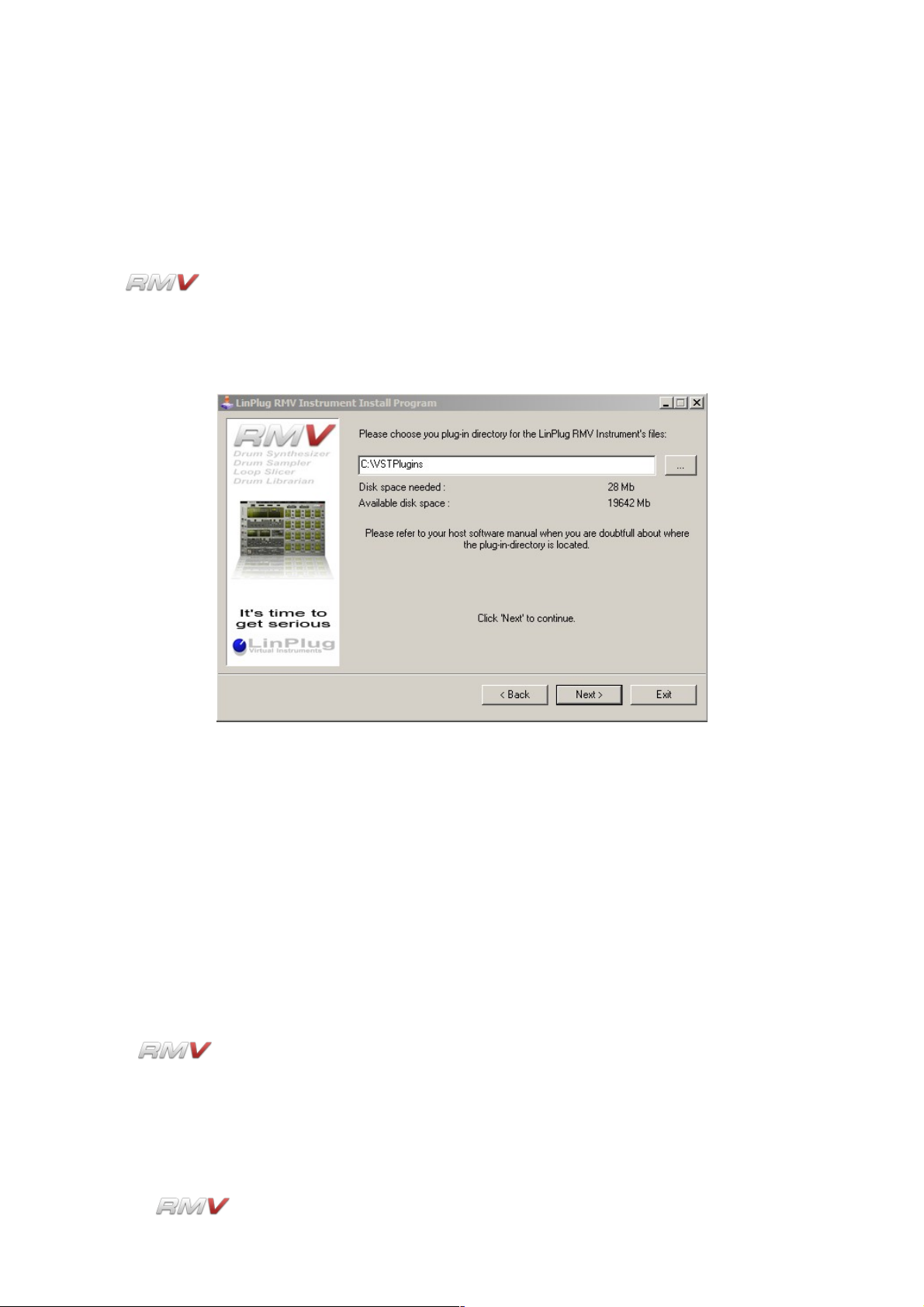
begin the installation process. Once installation commences you will see the window
shown below:
By clicking the three dots on the right of the installation path textbox you can choose the
plug-in directory to which the instrument will be copied. Refer to your host software's
manual if you are unsure about where the host software plug-in directory is located.
After selecting the desired directory click the "Start" button. In a similar manner you can
later on choose a folder for the RMV's data, so you can place the library on a different
drive or wherever it best suits your system.
The next time you start your host software the RMV will be listed in the VST Instrument
list. Refer to your host software's manual if you are unsure about where VST Instruments
are listed in the host software.
Once is installed it must be registered using your personal serial number. This
registration process is described in the Registration section of this manual.
If you have any questions regarding the installation of the RMV please contact us via our
support form at www.linplug.com/support/support.htm
LinPlug Reference Manual 5.0.1 9
Page 10

Installation and Activation
OS X Installation
The has been designed to run on computers using the Mac OSX 10.3 to 10.5
operating systems.
RMV comes with its own Installer. After downloading RMV you will find a file named
"RMV5xx.dmg" located in your web browser’s download folder. Double-click this file to
decompress and open the image, then double-click the installer program to begin the
installation process.
The installer will guide you through the installation process. The next time you start your
host software RMV will be listed in the AU and VST instrument list.
Once is installed it must be registered using your personal serial number. This
registration process is described in the Registration section of this manual.
If you have any questions regarding the installation of the RMV please contact us via our
support form at www.linplug.com/support/support.htm
LinPlug Reference Manual 5.0.1 10
Page 11

Features
Features
• Forty-eight polyphonic Percussion Pads
• Six Audio Loop Modules (each with up to 64 Slices)
• Available for Mac OSX and PC.
• Up to thirty-two-voice polyphony
• Multiple instances of the instrument can be opened.
• Internal 32/64 bit processing.
• Each Percussion Pad and each Slice includes its own controls for Volume, Pan,
Output Selection, Tune (+- 24 semitones in 10 cent intervals), Polyphony
(mono...8, full), two independent Effects Send, and a MIDI activity display.
• Each Pad and Slice can belong to one of 10 Edit Groups (parameters for all Pads or
Slices in a Group can be adjusted simultaneously)
• Each Pad additionally includes its own controls for loading and saving Pad files,
Choke Group (12 groups are available including prev/next and self-mute), Trigger
Key, Polyphony (mono...8, full), Mute and Solo.
• Each Pad and each Slice has access to a own 12x12 Modulation Matrix, three
independent LFOs, two separate distortion effects processors (Distortion and
BitCrusher), a multi-mode AHDSR-controlled filter, a four-band parametric equalizer,
three insert effects racks each of which can be set to one of nine different effects
units, and a "Varizer" for unbeaten realistic humanizing.
• Upon mouse over and editing the Pad and Slice displays automatically show
parameter settings.
• Pads and Audio Loop Modules provide mono and true stereo sample playback and
processing (all filters and effects are mono and stereo).
• A wide range of different Sampler and Synth Audio modules which include:
- A percussion sampler module.
- Two different kick drum modules.
- Two different snare drum modules.
- Open and closed hihat modules.
- A Tom module.
- A Clap module.
- Two cymbal modules.
- A percussion module.
- A universal purpose drum synthesizer
- Six independent Audio Loop Modules.
• Each Sampler module can hold up to 30 samples that can can have individual
volume settings and can be layered, velocity-switched or velocity-crossfaded, can
be played forwards or backwards.
• Sampler also features a Pitch Envelope with two successive Pitch and Time phases
and a AHDSR Envelope for controlling Amplitude.
• Sample Waveform Display shows the audio waveform as well as the Pitch
Envelope, Amplitude Envelope and Filter Envelope.
• Samples can also be opened and edited in an external editor and then reloaded into
the RMV right from RMV user interface.
• The Amplitude Envelope Release Time can be set to "endless" so that long samples
LinPlug Reference Manual 5.0.1 11
Page 12

Features
are not cut off before they have finished and can be set to respond to MIDI Note
Off.
• Sample playback parameters can be edited using snap-to-zero-crossing point.
• Supported sample formats: WAV 8-32 bit, mono and stereo, any samplerate, AIF
8-24 bit, mono and stereo, any samplerate.
• Samples, Pads, Kits, Grooves and Loops can be browsed while the instrument is
playing.
• The paths to samples, Pads, Kits, Grooves and Loops are saved when the file
dialog is closed so that when the file dialog is re-opened, it opens at the same
location.
• Dial response is switchable between linear and circular modes.
• Display can show either note numbers or note names.
• Adjustable Velocity response curve.
• Allmost all instrument parameters are MIDI controllable
• MIDI Learn supporting conventional and Alpha Dial controller.
• Sample accurate timing.
• Instrument comes with a vast selection of partly multisampled acoustic and
electronic kits and synthesized kits.
• Four specialized “Librarians” are now incorporated into the RMV. Each Librarian
has sophisticated search capabilities and is used for the storage and retrieval of
various types of data that the instrument supports. The Librarians can be used with
Pads, Kits, Grooves and Loops.
• Samples can be searched using the Sample Browser with prelistening
• The Kit Librarian features a “Live” control that enables different Kits to be loaded
using MIDI program change messages.
• Each of the instrument's 48 Pads has access to three Insert Effects Racks and
three Send Effects Racks, each of which can be set to one of nine different Effects
Units.
• Six independent Loop Players are available. Each Loop Player can be used to load
and playback audio loops in WAV, AIF, REX and REX2 format. Samples can be
automatically sliced.
• Slice start and end points, as well as automatic slicing sensitivity are user-definable.
• The output of the Pads and Loops can be mixed using the instrument's Master
section.
• Note Selects Pad (NSP). When a note is received via MIDI the instrument switches
to the Pad to which the note is set. This means that you always edit the Pad that
has just been triggered.
• An “intelligent” MIDI Mapper ensures that MIDI files are played back correctly even
when the Kit used to play them does not exactly match the contents of the MIDI file.
The Mapper ensures that the closest matching sound in the current Kit is used to
play back the MIDI messages. For example, if a specific HiHat sound is not in the
current Kit, the Mapper selects the next-best HiHat sound from the kit.
• Map 35 to 84 maps MIDI note number 35, which is outside the range of most MIDI
keyboards to MIDI note number 84.
• Mouse-wheel support (on PC).
LinPlug Reference Manual 5.0.1 12
Page 13

What's New in the RMV
What's New in the RMV
• The RMV's user interface has been completely redesigned. The instrument now
features 48 Pads displayed on three 4x4 panels. This means that the user
interfaces now matches hardware drum machines more closely. In addition to this,
there are six Loop Panels, a Send Effects section and a Master section. The Rear
Panel has been moved to the Setup Panel.
• A dedicated, universal drum synthesizer has been added to the RMV's Audio
Modules. The new drum synthesizer features an oscillator with a wide frequency
range, multiple source waveforms, a noise oscillator with a multimode filter, and a
wide range of modulation possibilities. The drum synthesizer is simple, versatile and
sounds amazing! We're confident that you won't need any other drum synthesizer.
Six independent Loop Players are available. Each Loop Player can be used to load
and playback audio loops in REX format. In addition to this, audio samples can be
loaded and manually or automatically sliced. Slice start and end points, as well as
slice sensitivity are user-definable. Slices can be opened and edited in an external
editor and then reloaded into the RMV. All slice editing is non-destructive. Each
slice can be individually processed by various envelopes, LFOs, a Filter, a complete
Modulation Matrix, and can be processed using Insert and Send effects. Multiple
Slices can be edited simultaneously using Edit Groups.
• Each of the instrument's 48 Pads has access to three Insert Effects Racks, each of
which can be set to one of nine different Effects Units. The available effects include
Delays, Reverbs, WahWah, Distortion and Filter, Equalizer, Compressors, Flanger
and Phaser.
• Each of the instrument's 48 Pads has access to three Send Effects Racks, each of
which contains four Effects Slots that can be set to one of nine different Effects
Units. The available effects include Delays, Reverbs, WahWah, Distortion and Filter,
Equalizer, Compressors, Flanger and Phaser.
• Each of the instrument's 48 Pads has access to three individual LFOs.
• The Modulation matrix has been extended so that it now has 12 slots. It also
contains several new modulation possibilities.
• A key feature of the RMV is the addition of several “Librarians” that are used for the
storage and retrieval of various types of data that can be used with the instrument.
Four Librarians are available. These are for Pads, Kits, Grooves and Loops. Each
Librarian includes sophisticated search capabilities.
• Samples can be searched using the Sample Browser.
• The Kit Librarian features a “Live” control that enables different Kits to be loaded
using MIDI program change messages.
• The RMV's Master section is used to mix the output of the Pads and Loops.
• The maximum size of an RMV Kit has been increased to 48 Pads. The 48 Pads are
arranged into 3 groups of 16 so as to match current hardware controllers. Because
the 48 Pads are arranged into 3 groups of 16 it also means that there won't be a
large number of unused Pads when working with small Kits.
• An “intelligent” MIDI Mapper ensures that MIDI files are played back correctly even
when the Kit used to play them does not exactly match the contents of the MIDI file.
The Mapper ensures that the closest matching sound in the current Kit is used to
LinPlug Reference Manual 5.0.1 13
Page 14

What's New in the RMV
play back the MIDI messages. For example, if a specific HiHat sound is not in the
current Kit, the Mapper selects the next-best HiHat sound from the kit.
• The RMV comes with the complete library of Drum Kits and single Hits found in the
RM IV. In addition to this, several new Kits and a large selection of up-to-date and
exciting Loops have been added. The new Kits and Loops have been produced
exclusively for the RMV by some of the world's best sound designers.
• Note Selects Pad (NSP). When a note is received via MIDI, the instrument
automatically switches to the Pad to which the note is set. This makes editing Kits
or Loops much faster.
• A range of improvements have been made to the RMV's internal audio engine.
These include:
- Voice Limit per Hit
- Fixed position per Pad. This ensures that a Pad always has the same pan
position, independent of the Kit or Kit type that is currently loaded. This means
that a sound's pan position remains constant whether it's part of an RM IV Kit,
an RMV Kit, or any of the supported import formats. Sounds are panned so that
they maintain a 1:1 match with your hardware controller (this feature supports
any Akai MPD or M-Audio Trigger controller).
- Parameter Readout upon mouse-over
- Adjustable Envelope shape
- Many improvements in the dedicated drum synth modules (Clap, Kick, Snare,
etc.)
- Modulation in the Matrix can now be “one-shot” or continuous. In the case of
“one-shot” modulation, a modulator's current value is captured as a “snapshot”
when a sound is triggered. Alternatively, a modulator's value can be used to
continuously modulate a sound.
- Envelopes can now be used in Normal Mode, One-Shot Mode or Loop Mode.
• Map 35 to 84. General MIDI defines two kick drums (at note number 35 and 36).
This can be inconvenient as many MIDI keyboards end at note number 36. Map 35
to 84 makes it possible to trigger the sound at note number 35 using note number
84 (C5) which is found on most MIDI keyboards.
LinPlug Reference Manual 5.0.1 14
Page 15

Overview
Overview
The is a 64-note-polyphonic VST percussion synthesizer and sampler, Audio
Loop Player and Slicer, MIDI Groove Player and Drum Librarian. The instrument is
designed specifically for creating and playing synthetic percussion sounds, as well as
playing sampled percussion sounds. The instrument can also be used for playing loops
and non-percussion sounds.
The synthesis algorithms used in the RMV have their roots in classic analogue drum
machines like the Roland TR808 and TR909. However, while the RMV can replicate many
of the sounds of these classic analogue drum machines, it also extends them into new
sonic territory and so has far greater creative potential.
The RMV consists of 48 Pads, each of which uses one of the instrument's Audio Modules
(a Pad can be set to play one of the percussion synthesis modules, the Sampler module,
or one of the Loop modules) to generate sound. Each Pad has its own dedicated set of
controls which include Display, Pan, Tune, Volume, Output, Choke Mode, Mute, Solo and
Trigger. Each Pad also incorporates three LFOs, an AHDSR-controlled multi-mode filter,
an EQ, an Insert Effects section, a Varizer, as well as a 12 x 12 Modulation Matrix. A Send
Effects section and Master section are also present.
The RMV is divided into 13 sections: Audio Module, Pad, Filter, Filter Envelope, EQ, Insert
Effects, Varizer, Send Effects, Modulation Matrix, Master, Kit, Groove, and Setup Panel.
The instrument also includes several Librarians which are used for searching and storing
instrument settings.
Audio signals are generated by any one of the RMV's Audio modules (one of the
percussion synthesis modules, the Sampler module or a Loop module) which get trigger
information from the synthesizer's MIDI input or from mouse-clicks on a Pad's Trigger
button. The RMV receives MIDI on all Channels simultaneously (this can be changed on
the instrument's Setup panel). The various parameters for the synthesis modules, which
differ according to the individual algorithm, can be set in the RMV's Audio module section.
The parameters for the Sampler module can also be set in this part of the RMV. The
parameters for the six Loop modules are set on their respective panels.
The RMV contains twelve different synthesis modules. Eleven of the synthesis modules
are designed to produce a specific type type of percussion sound such as kick drum
sounds or snare drum sounds. The Drum Synth module is multi-purpose and can be used
to produce a range of percussion sounds.
The RMV's Sampler module can be used to load up to 30 samples into an individual Pad.
It can also be used to view the samples once they are loaded. The Sampler module is
made up of three separate components: The Sample Display, The Pitch Envelope and the
Amplitude Envelope. The Sample Display shows various parameters for the currently-
LinPlug Reference Manual 5.0.1 15
Page 16

Overview
loaded sample/s. It can also be used to show the sample's envelope settings (Pitch,
Amplitude and Filter). The Sampler module has two envelopes available for each Pad:
Pitch and Amplitude. It's important to note that these envelopes apply to all of the samples
currently loaded into the module.
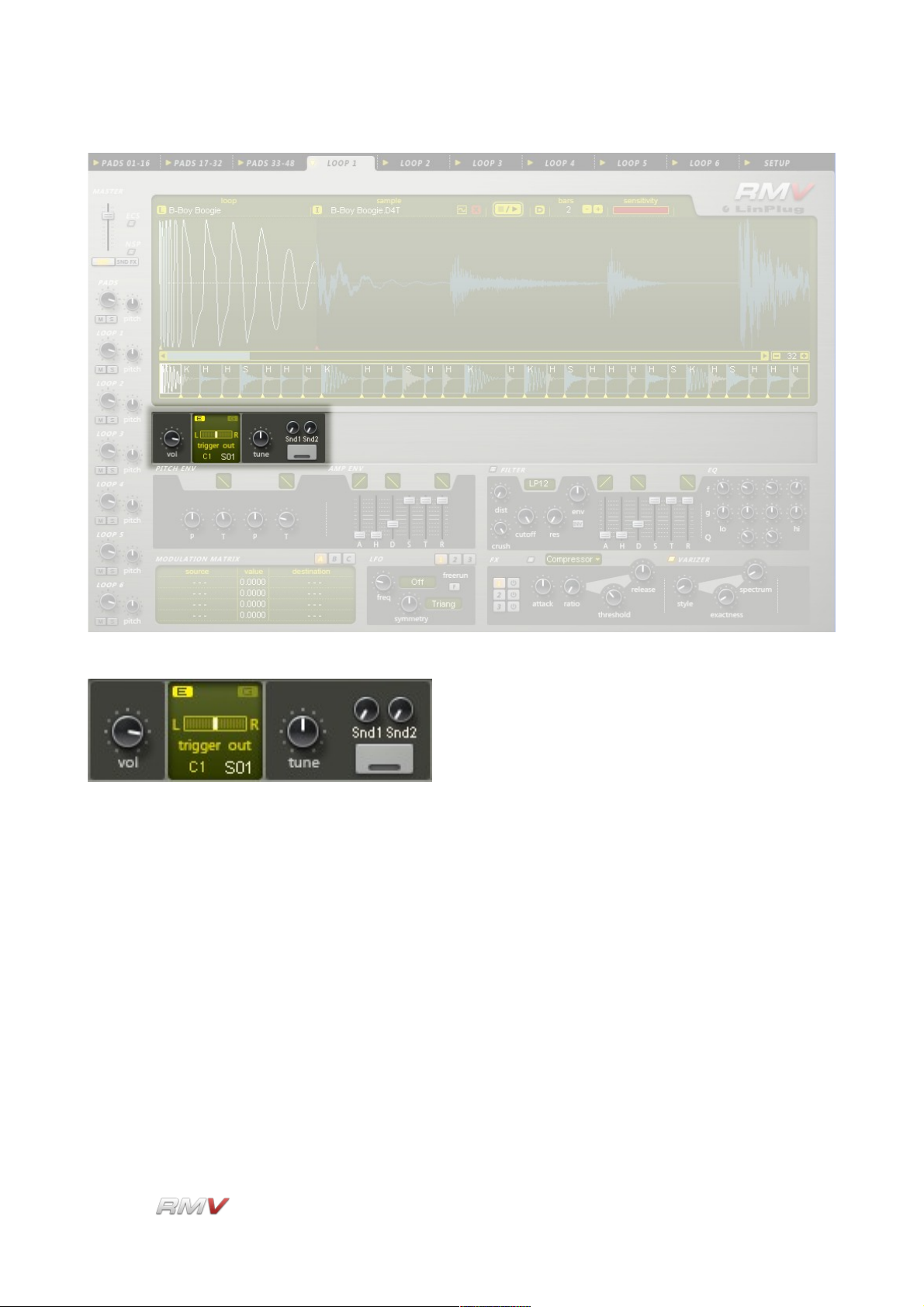
The RMV's Loop module is used to load either samples or audio loops. In the case of
samples, the file is automatically sliced into segments. Each segment of the sample/loop
can then be triggered independently via the host software. Each Loop module has
envelopes available for controlling the loop's pitch and amplitude.
The signal from each Audio Module is processed via the RMV's internal signal path. The
signal is first sent to an LFO section containing three independent LFOs. From here the
signal is sent to a multi-mode AHDSR-controlled filter and EQ. This section also
incorporates BitCrusher and Distortion effects.
Following the Filter/EQ section is an Insert Effects section containing three Insert Effects
Racks, each of which can be set to one of nine different Effects Units. A "Varizer" with
controls for Style, Precision and Spectrum is also available as a separate effects unit.
Each Pad also has access to a Send Effects section. The Send Effects section is arranged
into seven independent Sets of Effects Racks. One Set of Effects Racks is for use with the
RMV's 48 Pads. The remaining six Sets of Effects Racks are for use with each of the
instrument's six Loop Pads. Three separate Effects Racks are available in each Effects
Set. Each Effects Rack contains three Effects Slots and an EQ. Each Effects Slot can be
set to one of nine different Effects Units. For each Effects Set, the three Effects Racks are
in parallel. The output of the three Effects Racks in each Set is mixed together before
leaving the Send Effects section.
Finally, the signal from the Pads is mixed in the RMV's Master section before being output
to the host software. Note that the output of the Send Effects Racks can be sent directly to
the host software independently of the Master section.
The RMV's Modulation Matrix enables 12 user-defined modulation routings to be created.
26 modulation destinations are available for modulation by 23 modulation sources.
The audio outputs of the RMV are automatically connected to the input of the host
software's mixer.
Finally, the RMV's Setup Panel enables various global parameters including Power Pan,
Pad Velocity, Linear Dials, Note Names, as well as various MIDI and file search path
parameters to be set by the user.
Hopefully, this chapter has provided a brief overview of the internal workings of the RMV.
More detailed information can be found in the following chapters.
LinPlug Reference Manual 5.0.1 16
Page 17

Controls
Controls
Users have the option of controlling all dials in either a circular or a linear manner
depending on the Dial Mode setting on the RMV's Setup Panel (see the "Setup Panel"
section of this manual for more information).
Holding down the ALT key while clicking on a control changes the selected control's value
a minimum step upwards (when clicking in the upper half of the control) or a minimum step
downwards (when clicking in the lower half of the control). The value of the minimum step
varies depending upon the control.
Holding down the CTRL key while clicking on a control sets the control to its default value
(e.g. for Volume controls it sets the control's value to -3 dB). The value of the default
setting varies depending upon the control.
Holding down the SHIFT key while changing a control's value enables finer control values
to be set.
When controls are changed, the value of the control is displayed in the corresponding
active Pad's Data Display. After a short period of time the Data Display reverts to showing
the title of the respective Pad. This applies to all RMV pad controls except those found in
the Audio Modules and the Modulation Matrix.
All controls can be automated and controlled using external MIDI messages. To use
external devices it is necessary to use the RMV's ECS which is described in detail later in
this manual.
PC users who have a mouse with a wheel can use the mouse-wheel to change RMV
parameter values provided that the host software supports this (an example of a VST host
program that supports the use of mouse-wheels is Cubase).
LinPlug Reference Manual 5.0.1 17
Page 18

Optimizing CPU Usage
Optimizing CPU Usage
Software synthesizers are highly CPU-intensive. The real-time calculation of audio
waveforms, filters, effects and modulators places a significant load on the host computer's
CPU.
As such, the main limiting factor in software synthesizer performance is CPU processing
power. Each additional oscillator, filter, effect and modulator that is included in an
instrument adds to the CPU load. As a result, it's best to switch off any unused units within
the RMV to conserve CPU resources. It may also be useful to use the send effects of your
host's mixer instead of the RMV's effects as they are shared among all instruments.
LinPlug Reference Manual 5.0.1 18
Page 19
Pads
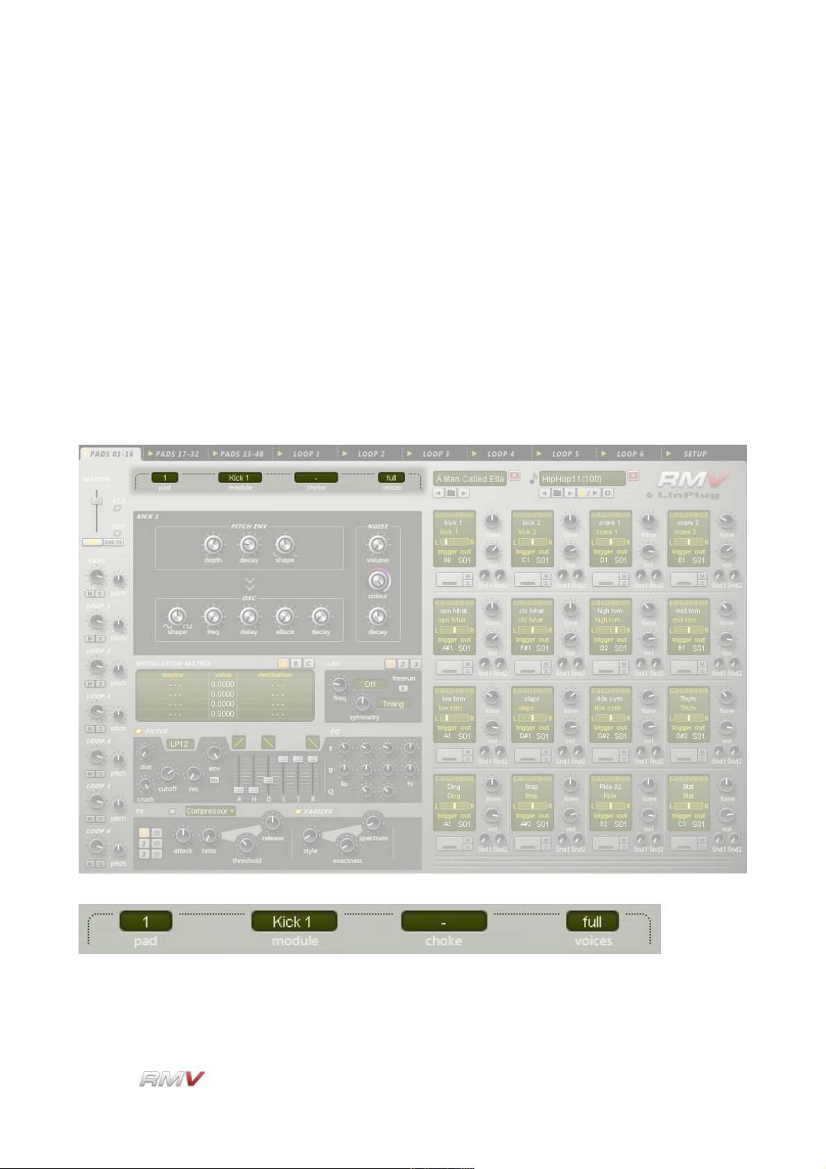
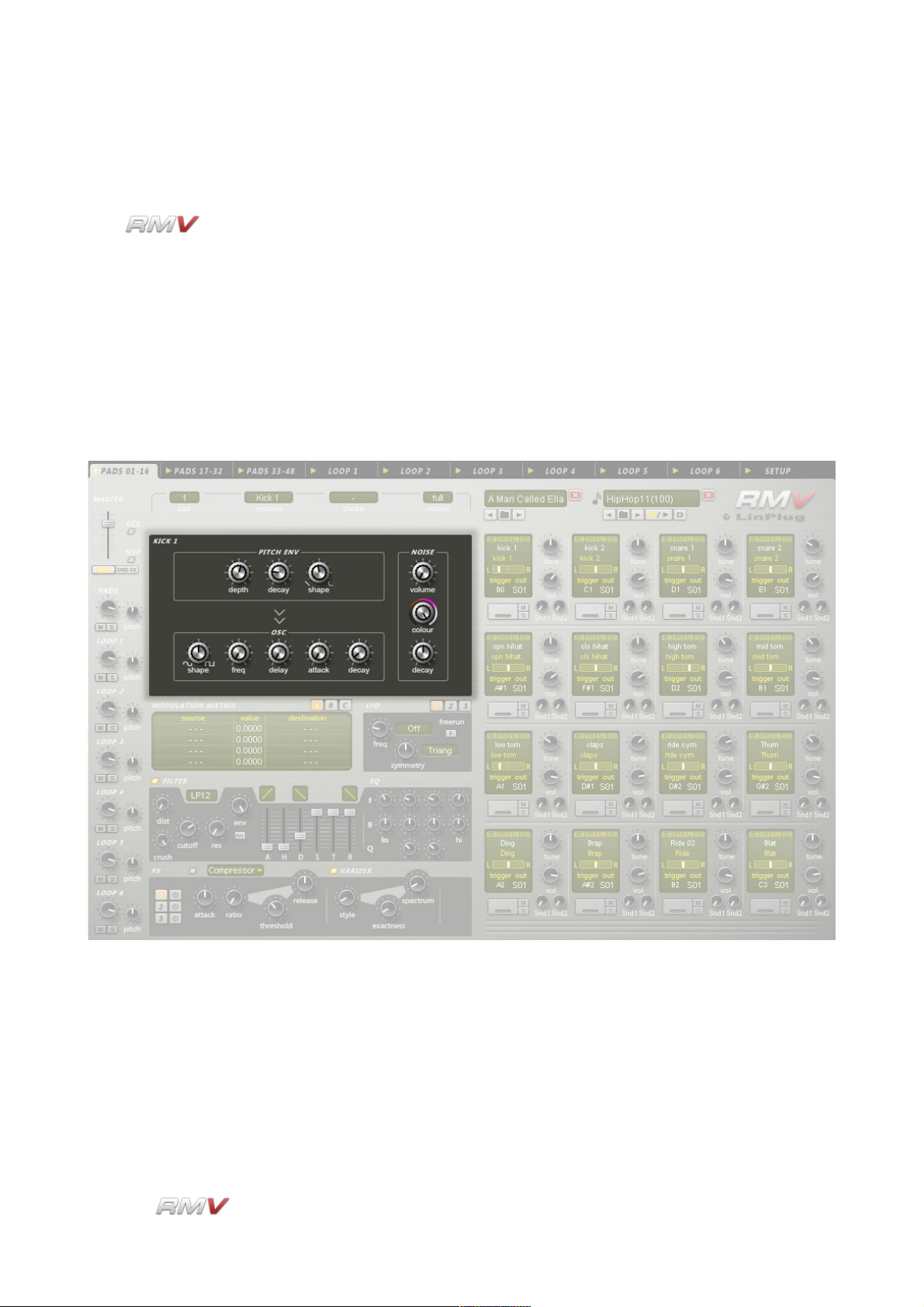
Pads
The contains 48 Pads. Forty-eight of these Pads are used for triggering the
instrument's Audio Modules. These are arranged into three sets of 16 Pads and are
accessible using the tab controls at the top of the instrument. The remaining six Pads are
used to trigger audio loops and are located in the instrument's six Loop Modules.
Each of the Pads located in instrument's Pad section can be used to trigger a particular
Audio Module (any one of the drum synthesis modules or the Sampler module) that can be
selected by the user. Each Loop Module contains its own dedicated Pad that can only be
used with that particular module.
The RMV's Pads are numbered in horizontal rows from the top
of the instrument to the bottom. Only one Pad is active at a
time. The currently active Pad is shown by an illuminated “E”
indicator located in the top left corner of the Pad. The
instrument displays the Audio Module for the currently active
Pad, as well as the settings of its signal processing path. To
change to a different Pad click on either the “E” button or any
control in the desired Pad. A new Pad can also be selected
using the Pad control located above the Audio module section.
This control also displays the currently active Pad.
LinPlug Reference Manual 5.0.1 19
Page 20
Pads
When a new Pad is selected, the RMV's display is updated so that it shows the Audio
Module and the signal processing path of the currently active Pad.
The 48 Pads found in the instrument's 3 Pad sections can be used to trigger any one of
the RMV's selection of Audio modules. The modules that use percussion synthesis
algorithms to generate sound are described in more detail in the Percussion Synthesis
Module section of this manual. One of the Audio modules uses sampling to playback
sounds. This module is described in the Sample Module section of this guide.
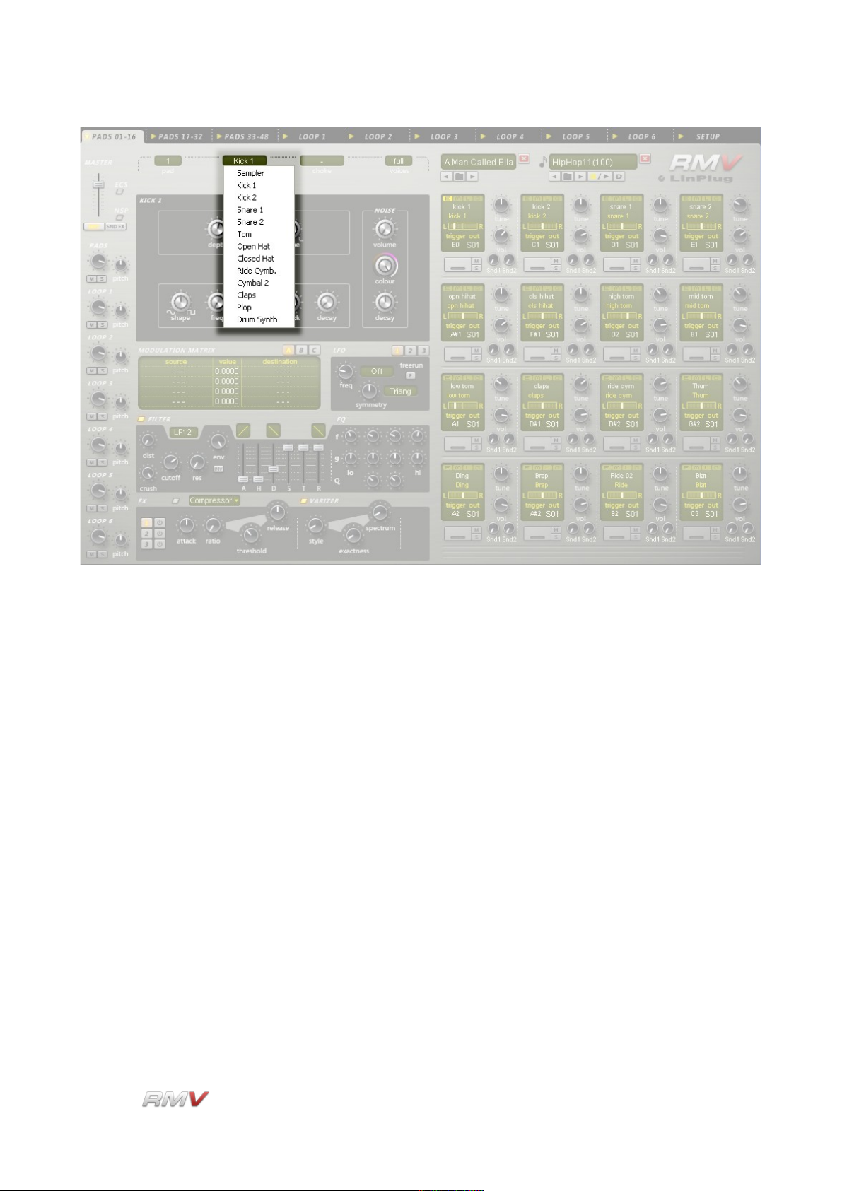
An Audio module is assigned to a Pad using the Module control located directly above the
Audio module section. To do this, first, select the desired Pad, and then select one of the
RMV's Audio modules from the drop-down list. The selected module is now assigned to
the Pad. Note that the number of the currently active Pad is shown in the Pad control
which is located to the left of the Module control. It is also possible to change Pads by
clicking and dragging on the Module control.
LinPlug Reference Manual 5.0.1 20
Page 21

Pads
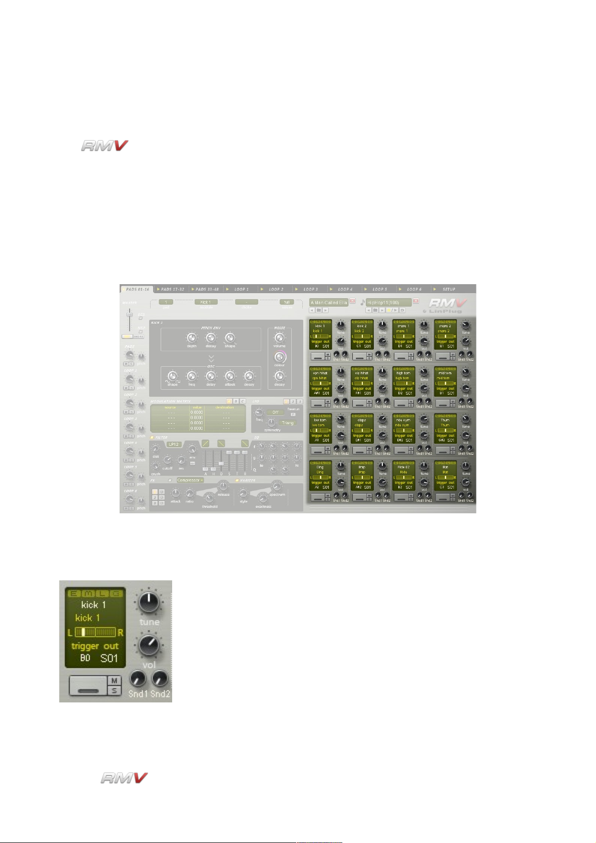
Each Pad in the RMV's 3 Pad sections is identical and consists of 19 controls. These are:
E, M, L, G, Title, Pan, Trigger Note, Out(put), Trigger Button, Mute, Solo, Tune, Vol(ume),
Snd1 (Effects Send 1), Snd2 (Effects Send 2), Choke, Voices, Pad and Module. These
described in detail below. The first fifteen controls are located on the Pad itself. The other
four controls are located above the Audio Module section.
E (Edit): The E (Edit) Indicator (the small light at the top left of each Pad
section) shows the Pad that is currently active. A different Pad can be
selected by clicking any control in the desired Pad.
M (Menu): The M (Menu) control is used to open a popup menu containing 4
items related to the Pad's settings. These items are: Save, Copy, and
Paste. The Save menu item enables the current Pad settings to be
saved to a .PAD file. The file is saved to the RMV's internal Pad
library. The Copy menu item enables the current Pad settings to be
copied, while the Paste menu item enables the copied settings of
another Pad to be applied to the current Pad.
L (Load): Clicking on the L (Load) button opens the Pad Librarian. The Pad
Librarian enables Pads to be loaded and saved. See below for more
information about the Pad Librarian.
G (Group): Each of the RMV's Pads can be assigned to a Group. Assigning a
Pad to a Group enables all Pads in that Group to be edited using the
controls of a single Pad. To set a Pad to a Group, click and drag on
the G (Group) button until the desired Group is displayed. Ten
Groups are available. Note that Group editing is relative which
means that if the value of one control in a Group is changed, the
other controls in the Group are changed by the same amount. They
are not set to the same value as the first control.
Attention: to change all Pads in a Group, use the right mouse button.
With the left mouse button you only change the current Pad, even
when it has been assigned to a group!
Title: A Pad's settings can be named using the Title control which is
located below the E, M, L and G controls. The name of the Pad is
saved with the Kit that it is a part of.
Data Display: Each Pad has its own Data Display that shows the value of the
parameter currently being edited. For example, if the value of the
Amplitude Envelope's Attack Time is changed, the value is displayed
in the current Pad's Data Display.
Pan: The Pan control is used to set the stereo position of the Pad's output
and is located below the Pad's Data Display. The Pan control has a
range of 1.00 L to 1.00 R. A setting of "C" places the output in the
LinPlug Reference Manual 5.0.1 21
Page 22

Pads
centre of the stereo field. Note that if the Pad's output is set to a
mono destination the Pan control has no effect.
Trigger (Note): The Trigger (Note) sets the MIDI note that triggers the Pad. This
parameter only applies to the Percussion Synthesis modules. The
Trigger (Note) for the Percussion Sampler module is set on a persample basis in the Sampler window on the RMV's Front Panel (see
the Sampler section of this manual for more information about the
RMV's Percussion Sampler module).
Out(put): The Out(put) control is used to set the output destination of the Pad.
Available destinations depend upon the instrument's current audio
output settings. Note that all stereo outputs are listed first, followed
by all of the mono outputs.
Trigger Button: The Trigger button allows the Pad to be played using the mouse. To
activate the Trigger button click the mouse on the button. If Pad
Velocity is enabled on the RMV's Setup Panel (see below for more
information about the RMV's Setup Panel), the Pad becomes
velocity-sensitive. In this case, as the cursor is moved from left to
right over the Trigger button, the trigger velocity increases. In other
words, clicking on the left of the button triggers the Pad at lower
velocities than clicking on the right of the Pad. The Activity Indicator
shows that the Pad has been triggered. It stays lit until the Pad has
finished playing.
Mute: The Mute button silences the output of the selected Pad.
Solo: The Solo button silences all Pads other than the ones that are
selected. Note that more than one Pad can be soloed at a time. This
is useful if you want to listen to particular combinations of Pads in
isolation.
Tune: The Tune control sets the Pad's tuning. The available range is +- 24
semitones in 10 cent steps.
Vol(ume): The Vol(ume) control is used to set the output volume of the Pad.
The available range is -oo to +6 dB. The default value is -3 dB.
Snd1 Amount: Each Pad can send its output to the Effects Racks in the RMV's Send
Effects section (see the Send Effects section of this manual for more
information about the RMV's Send Effects). The percentage of the
signal sent to the Effects Rack selected using the Snd1 Destination
control is set using the Snd1 Amount control.
LinPlug Reference Manual 5.0.1 22
Page 23
Pads
Snd1 Destination: The Snd1 Destination control is used to set the destination of a Pad's
first Effects Send. Three destinations, Snd1, Snd2 and Snd3 are
available. Each corresponds to one of the RMV's three Send Effects
Racks. Note that only one destination is active at a time.
Snd2 Amount: Each Pad can send its output to the Effects Racks in the RMV's Send
Effects section (see the Send Effects section of this manual for more
information about the RMV's Send Effects). The percentage of the
signal sent to the Effects Rack selected using the Snd2 Destination
control is set using the Snd2 Amount control.
Snd2 Destination: The Snd2 Destination control is used to set the destination of a Pad's
second Effects Send. Three destinations, Snd1, Snd2 and Snd3 are
available. Each corresponds to one of the RMV's three Send Effects
Racks. Note that only one destination is active at a time.
Pad: The Pad control is located directly above the Audio module section.
The Pad control is used to select a Pad for editing. To select a Pad
LinPlug Reference Manual 5.0.1 23
Page 24

Pads
for editing, click and drag on the Pad control until the desired Pad
number is shown.
Module: An Audio module is assigned to a Pad use the Module control
located directly above the Audio module section. Thirteen different
Audio modules are available. The Audio modules are described in
the Audio module section of this manual. To set the Audio module for
a particular Pad, first, select the desired Pad, and then select one of
the RMV's Audio modules using the Module control. The Audio
module is now assigned to the Pad.
Choke: The setting of the Choke control determines which of the RMV's
various choke modes is used. The available choke modes are:
"-" No Choke is applied to this Pad.
"me" Whenever this Pad is triggered, it chokes itself.
"prev" Whenever this Pad is triggered, the previous Pad is choked.
"nxt" Whenever this Pad is triggered, the next Pad is choked.
"1"..."9" The RMV has 9 user-definable choke groups. Whenever an
Instrument in a particular choke group is triggered all other
instruments in that choke group are muted. This is typically used to
simulate the way that real drums generate sound. For example, an
open hihat is "choked" or muted when the drummer closes it with the
footpedal. As such, open and closed hihats often form a choke group.
Voices: The Voices setting determines the maximum number of voices that a
Pad can play at a single time. This ranges from mono...2...8...full
("full" is equivalent to 64 voices). This control is especially useful for
instruments that sound for a long time such as cymbals.
LinPlug Reference Manual 5.0.1 24
Page 25
Pads
Pad Librarian
The can load and save data in a variety of different formats. One of these
formats is a Pad file. A Pad file contains all of the current settings of an individual Pad,
however it is important to note that a Pad file does not contain sample data, even in the
case where the Pad is set to use the Sampler module. The idea is that Pads are used to
build up Kits, however when a Kit file is saved, internally, it only contains references to
samples not to the pads it was initially made from. Although this may seem confusing the
reason behind this is as follows: if Kits were constructed from Pads then any changes
made to a Pad used by one Kit would also affect any other Kits that used the same Pad.
This is avoided by having Kits and Pads stored separately in the RMV's internal library.
The RMV features several Librarians which can be used for searching and saving files. A
search operation typically uses text or numeric information to search for files located in the
RMV's internal library. A Librarian can also be used to import files from outside the RMV's
internal library, as well as to save custom files to the internal library.
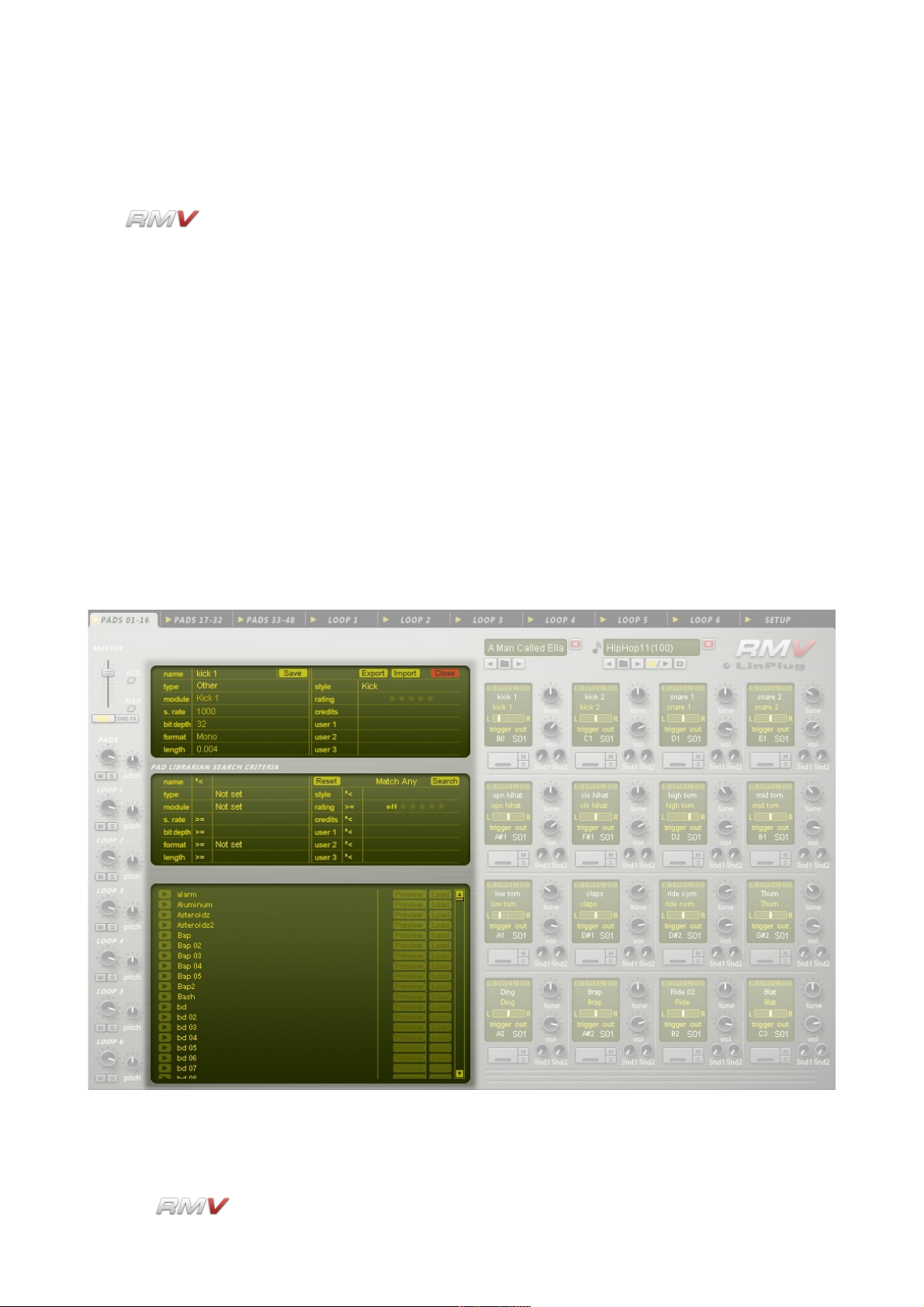
The RMV's Pad Librarian consists of three parts: the Information display, the Search
display, and the Search Result Display.
The Information display shows the attributes of the currently selected Pad. It also enables
LinPlug Reference Manual 5.0.1 25
Page 26
Pads
Pads to be Saved, Imported and Exported. The Pad Search Input display is used to set the
search parameters that are used when the RMV searches its internal Pad database. The
Pad Search Results display shows the results of the previous Pad search. Further details
of these three displays are presented below.
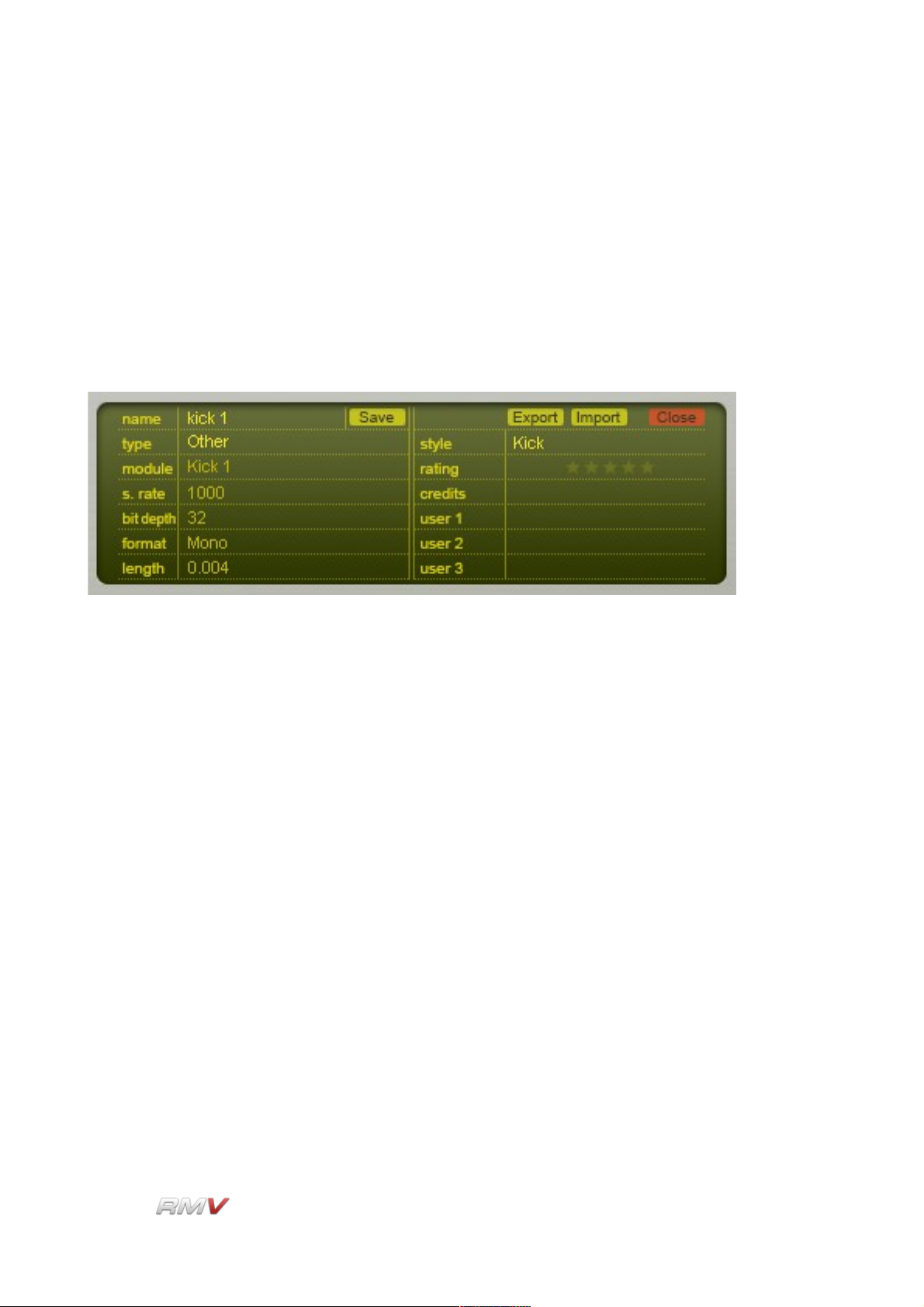
Pad Information Display
The Pad Information display shows the descriptive attributes of the currently loaded Pad. It
also enables a Pad's descriptive attributes to be set by the user prior to the Pad being
saved.
The Pad Information display operates in two ways. Firstly, when a Pad is loaded from
either the internal library or from an external location, the Pad Information display shows
the Pad's descriptive attributes (the actual attributes are listed below). Secondly, the Pad
Information display enables a Pad's descriptive attributes to be set prior to the Pad being
saved. Note that only some of the descriptive attributes can be edited by the user.
The following descriptive attributes can be saved in a Pad file:
Name: Displays the name of the current Pad file. This control is also used to
enter the name of the Pad when a new Pad is created.
Type: Displays the type of sound in the current Pad file. The Types of Pad
available are: Other, Kick, Snare, HiHat, OpenHat, Clap, Cymbal,
Tom, Rimshot, Click, Glitch and Latin.
Module: Displays the name of the Audio Module used by the current Pad File.
The Types of Audio Module available are: Not Set, Sampler, Kick 1,
Kick 2, Snare 1, Snare 2, Tom, Open Hat, Closed Hat, Ride Cymb.,
Cymbal 2, Claps, Plop and Drum Synth.
S.Rate: Displays the sample rate of the current Audio module's output.
Bit Depth: Displays the bit depth of the current Audio module's output.
LinPlug Reference Manual 5.0.1 26
Page 27

Pads
Format: Displays the number of channels of the current Audio module's
output.
Length: Displays the length of the Audio module's output (in seconds). In the
case of a sample, the Length is the actual length of the sample. In
the case of a synthesized signal, the Length represents the duration
of the output signal.
Style: Displays the style of sound in the current Pad file.
Rating: A rating of the quality of the Pad.
Credit: A reference to the creator of the Pad.
User 1: A user-definable Pad attribute.
User 2: A user-definable Pad attribute.
User 3: A user-definable Pad attribute.
Save: Saves the current Pad settings to the RMV's internal Pad library.
Export: Exports the current Pad settings.
Import: Imports a Pad file from an external location.
Close: Closes the Pad Librarian.
Pad Search Input Display
The Pad Librarian's Search Input section is used to set the criteria used when searching
the RMV's internal library for Pads.
Thirteen search keys are available. They are used in combination with mathematical
LinPlug Reference Manual 5.0.1 27
Page 28

Pads
operators to determine the parameters of the search. The thirteen search keys can be
divided into two types: text keys and numeric keys. The mathematical operators used with
each search key depend upon the type of the search key. Text keys can be searched using
the following operators: “=”, “*<” and “<*>”. Numeric search keys can be searching using
the following operators: “<”, “>”, “=”, “<=” and “>=”. These operators are described below.
In addition to this, the Pad Search Input section enables any or all of the selected criteria
to be used in the search. The search is performed using the Search button. The search
criteria can be set to the display's default values using the Reset button. Note that the
Type and Module search keys can only be set to predetermined values.
Text Operators:
=: Equal to. The “Equal To” operator finds all items in the database that
are exactly the same as the search term.
*<: Begins with. The “Begins With” operator finds all items in the
database that begin with the search term.
<*>: Contains. The “Contains” operator finds all items in the database that
contain the search term.
Numeric Operators:
<: Less Than. The “Less Than” operator finds all items in the database
that are less than the search term.
>: Greater Than. The “Greater Than” operator finds all items in the
database that are greater than the search term.
=: Equal To. The “Equal To” operator finds all items in the database that
are equal to than the search term.
<=: Less Than or Equal To. The “Less Than or Equal To” operator finds
all items in the database that are less than or equal to the search
term.
>=: Greater Than or Equal To. The “Greater Than or Equal To” operator
finds all items in the database that are greater than or equal to the
search term.
Search Key:
Name: The name, or portion of the name, of the Pad file to search for in the
internal library. The search results depend upon the operator used to
define the search (see above).
LinPlug Reference Manual 5.0.1 28
Page 29

Pads
Type: The type of Pad file to search for. The Types of Pad available are:
Other, Kick, Snare, HiHat, OpenHat, Clap, Cymbal, Tom, Rimshot,
Click, Glitch and Latin.
Module: The name of the Audio Module used by the Pad File. The Types of
Audio Module available are: Not Set, Sampler, Kick 1, Kick 2, Snare
1, Snare 2, Tom, Open Hat, Closed Hat, Ride Cymb., Cymbal 2,
Claps, Plop and Drum Synth.
S.Rate: The value of the sample rate used by the Audio module.
Bit Rate: The value of the bit rate used by the Audio module.
Format: The output format used by the Audio module (Stereo or Mono).
Length: The duration of the signal played back by the Audio module. In the
case of the Sampler module, this figure indicates the length of the
longest audio sample. In the case of synthesis-based Audio modules
this figure represents the duration of the output signal.
Style: The style of sound in the current Pad file.
Rating: The rating of the quality of the Pad.
Credit: The reference to the creator of the Pad.
User 1: The first user-definable Pad attribute.
User 2: The second user-definable Pad attribute.
User 3: The third user-definable Pad attribute.
General:
Reset: The Reset control restores the search parameters to their default
values.
Match: The match control enables the search to be defined so as to match
any or all of the selected criteria.
Search: The Search control starts the search of the internal Pad database.
LinPlug Reference Manual 5.0.1 29
Page 30
Pads
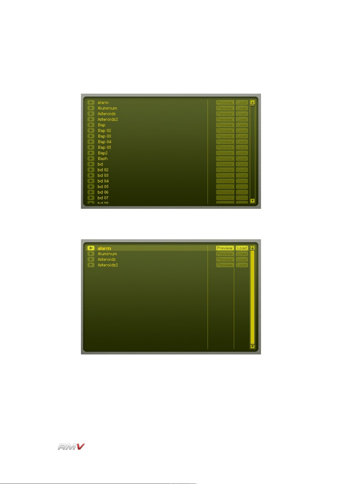
Search Results Display
The Pad Librarian's Search Results Display shows the results of a search of the RMV's
internal Pad library using the parameters supplied in the Pad Search Input section.
Prior to a Search, the Search Results section shows all the Pad files in the internal library.
After a Search, the Search Results section shows all the Pad files in the internal library
that match the search criteria entered in the Search Input section.
The Search Results section displays a list of all Pads that meet the search criteria. The
results are displayed as a list. The Search Results section has three controls. These are
Play, Preview and Load.
LinPlug Reference Manual 5.0.1 30
Page 31

Pads
Play: The Play button is located to the left of the Pad's name. The Play
button is used to play back the Pad's Audio module output without
any additional processing.
Preview: The Preview button is located to the right of the Pad's name. The
Preview button is used to temporarily load and play the Pad.
Previewing the Pad includes all of the processing that is applied to
the Pad including filtering, effects processing and enveloping.
Load: The Load button loads the Pad file into the currently active Pad.
Note that if the Pad Librarian is closed without a new Pad being loaded the Pad is restored
to its initial state.
LinPlug Reference Manual 5.0.1 31
Page 32
Audio Modules
Audio Modules
The produces sound using Audio modules. Three different types of Audio module
are available: (1) Percussion Synthesis modules, (2) a Sampler module, and (3) a Loop
module. Each type of module produces sound in a different way. This section describes
the RMV's Percussion Synthesis modules and Sampler module. The Loop module is
described in the Loop module section of this guide.
An Audio module functions as the sound source for a Pad, and is assigned to a Pad using
the Module control located above the Audio module section. The Audio module used by
the currently active Pad is shown in the Module display located above the RMV's Audio
module section.
At the same time, the user interface for the Audio module is displayed in the RMV's Audio
module section. Note that the Audio module is displayed for the currently active Pad, and
changes as different Pads become active.
LinPlug Reference Manual 5.0.1 32
Page 33
Audio Modules
Twelve different Percussion Synthesis modules are available in the RMV. Each is designed
to produce a particular type of percussion sound. The Sampler module is used to play
back audio samples and so can be used to play any type of sound.
LinPlug Reference Manual 5.0.1 33
Page 34
Audio Modules
Percussion Synthesis Modules
Each Percussion Synthesis module uses a unique synthesis algorithm to generate sound,
and so has its own unique set of controls. The various synthesis algorithms used in the
RMV's Percussion Synthesis modules are described in detail below:
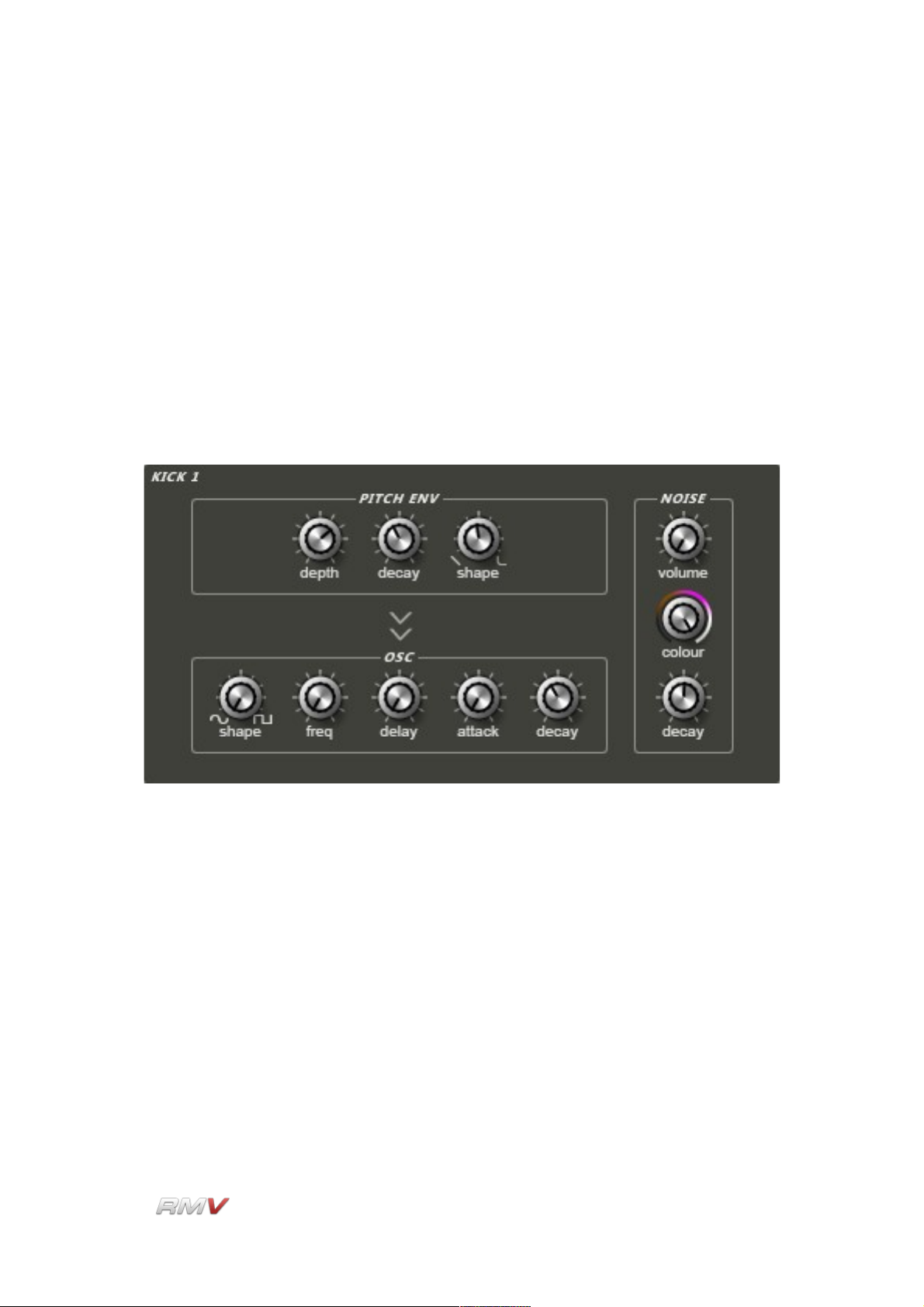
Kick 1
The Kick 1 Percussion Synthesis module is specifically designed for producing electronic
kick drum sounds.
The Kick 1 Percussion Synthesis module contains the following controls:
Pitch Env(elope) Depth: The Pitch Env(elope) Depth control determines the extent to
which the drum's pitch is controlled by the pitch envelope.
Pitch Env(elope) Decay (Time): The Pitch Env(elope) Decay (Time) control is used to
set the rate at which the drum's pitch returns to the fundamental
frequency.
Pitch Env(elope) Shape: The Pitch Env(elope) Shape control is used to set the shape of
the drum's pitch envelope. This can range from linear to extreme
exponential.
Osc(illator) Shape: The Osc(illator) Shape control is used to set the shape of the
LinPlug Reference Manual 5.0.1 34
Page 35

Audio Modules
oscillator waveform. When turned fully anti-clockwise the oscillator
produces a sine wave, while when turned fully clockwise the
oscillator produces a pulse wave.
Osc(illator) Frequency: The setting of the Osc(illator) Frequency control determines
the drum's fundamental frequency. The frequency changes from low
to high as the dial is turned in a clockwise direction. This control
interacts with the Tune control on the associated Drum Pad.
Osc(illator) Delay Time: The Osc(illator) Delay control is used to set the delay time
between the triggering of the oscillator and the time it starts playing.
The delay time increases as the dial is turned in a clockwise
direction.
Osc(illator) Attack (Time): The Osc(illator) Attack (Time) control is used to set the drum
oscillator's attack time. Setting this control to a high value delays the
onset of the drum waveform, creating damping or muffling effects.
Osc(illator) Decay (Time): The Osc(illator) Decay (Time) control determines how fast the
sound decays after it is triggered. The decay time changes from short
to long as the dial is turned in a clockwise direction.
Noise Volume: The Noise Volume control is used to set the amount of noise added
to the drum sound.
Noise Colour: The Noise Colour control setting determines the frequency spectrum
of the noise.
Noise Decay (Time): Noise Decay (Time) control is used to set the decay time of the noise
component of the drum sound.
LinPlug Reference Manual 5.0.1 35
Page 36
Audio Modules
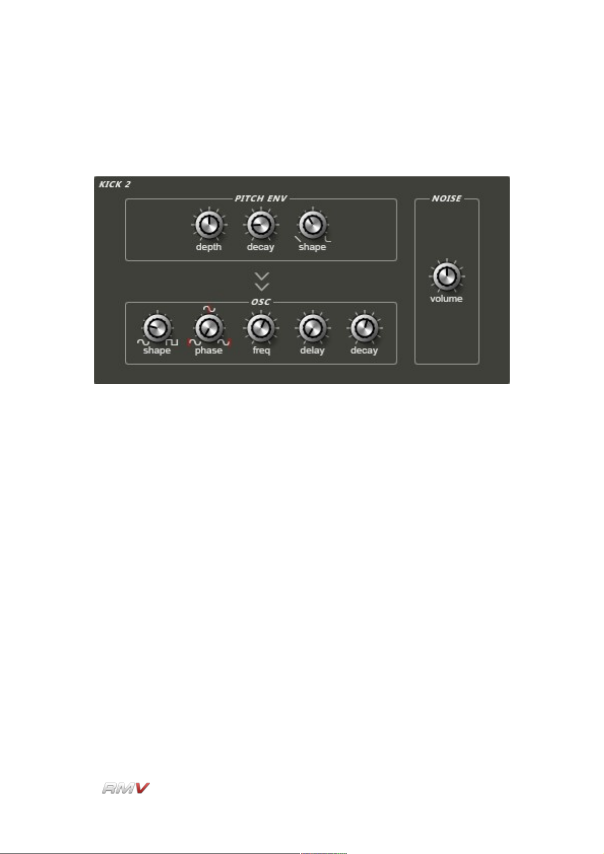
Kick 2
The Kick 2 Percussion Synthesis module is specifically designed for producing electronic
kick drum sounds.
The Kick 2 Percussion Synthesis module contains the following controls:
Pitch Env(elope) Depth: The Pitch Env(elope) Depth control determines the extent to
which the drum's pitch is controlled by the pitch envelope.
Pitch Env(elope) Decay (Time): The Pitch Env(elope) Decay (Time) control is used to
set the time taken for the drum's pitch to return to the drum's
fundamental frequency.
Pitch Env(elope) Shape: The Pitch Env(elope) Shape control is used to set the shape of
the drum's pitch envelope. This can range from linear to extreme
exponential.
Osc(illator) Shape: The Osc(illator) Shape control is used to set the shape of the
oscillator waveform. When turned fully anti-clockwise the oscillator
produces a sine wave, while when turned fully clockwise the
oscillator produces a pulse wave.
Osc(illator) Phase: The Osc(illator) Phase control is used to determine the starting point
in the oscillator waveform when it is triggered. In effect, this control
functions as a delay with a range of one waveform cycle. The starting
position of the oscillator's waveform is increased as the dial is turned
in a clockwise direction.
LinPlug Reference Manual 5.0.1 36
Page 37

Audio Modules
Osc(illator) Freq(uency): The setting of the Osc(illator) Frequency control determines
the drum's fundamental frequency. The frequency changes from low
to high as the dial is turned in a clockwise direction. Note that this
control interacts with the Tune control on the associated Drum Pad.
Osc(illator) Delay (Time): The Osc(illator) Delay (Time) control is used to set the delay
time between the triggering of the oscillator and the time it starts
playing. The delay time increases as the dial is turned in a clockwise
direction.
Osc(illator) Decay (Time): The Osc(illator) Decay (Time) control is used to determine the
time taken for the sound to decay after it is triggered. The decay time
changes from short to long as the dial is turned in a clockwise
direction.
Noise Volume: The Noise Volume control is used to adjust the amount of noise
added to the drum sound. As the dial is turned in a clockwise
direction more noise is added to the sound.
LinPlug Reference Manual 5.0.1 37
Page 38
Audio Modules
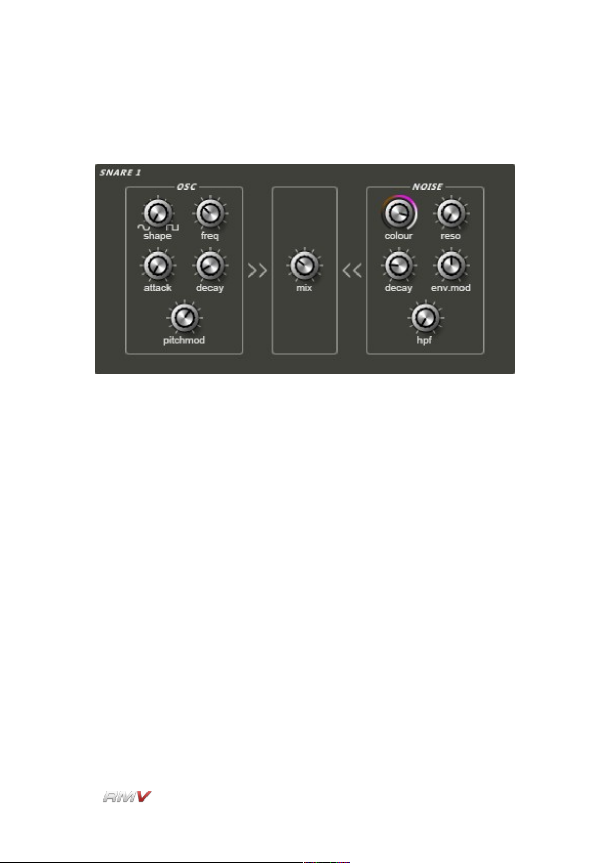
Snare 1
The Snare1 module combines an oscillator with a noise source.
The Snare 1 Percussion Synthesis module contains the following controls:
Osc(illator) Shape: The Osc(illator) Shape control is used to set the shape of the
oscillator waveform. When turned fully anti-clockwise the oscillator
produces a sine wave, while when turned fully clockwise the
oscillator produces a pulse wave. In intermediate positions the
oscillator produces a hybrid waveform.
Osc(illator) Frequency: The setting of the Osc(illator) Frequency control determines
the drum's fundamental frequency. The frequency changes from low
to high as the dial is turned in a clockwise direction. This control
interacts with the Tune control on the associated Drum Pad.
Osc(illator) Attack (Time): The Osc(illator) Attack (Time) control is used to set the drum
oscillator's attack time. Setting this control to a high value delays the
onset of the drum waveform, creating damping or muffling effects.
Osc(illator) Decay (Time): The Osc(illator) Decay (Time) control determines how fast the
sound decays after it is triggered. The decay time changes from short
to long as the dial is turned in a clockwise direction.
Osc(illator) Pitch Mod(ulation): The Osc(illator) Pitch Mod(ulation) control is used to set
the extent to which the drum's pitch is controlled by the oscillator's
pitch envelope.
LinPlug Reference Manual 5.0.1 38
Page 39

Audio Modules
Noise Colour: The Noise Colour control setting determines the frequency spectrum
of the noise generator.
Noise Reso(nance): The Noise Res(onance) control is used to set the amount of
emphasis around the noise oscillator's cutoff frequency. Higher
settings create a more pronounced peak in the signal while lower
settings produce a flatter response.
Noise Decay (Time): The Noise Decay (Time) control sets the decay time of the noise
component of the drum sound.
Noise Env(elope) Mod(ulation): The Noise Env(elope) Mod(ulation) control is used to
set the degree to which the noise oscillator's filter cutoff frequency is
modulated by the oscillator's amplitude envelope.
Noise HPF (High Pass Filter): The Noise HPF (High Pass Filter) control is used to set
the cutoff frequency of a high pass filter that processes the output of
the noise oscillator. Rotating the control in a clockwise direction
increases the cutoff frequency of the filter.
Mix: The Mix control is used to set the relative amounts of the pitched
oscillator and the noise oscillator in the output signal. Rotating the
control in the anti-clockwise direction increases the proportion of
pitched oscillator signal in the output, while rotating the control in the
clockwise direction increases the proportion of noise signal in the
output.
LinPlug Reference Manual 5.0.1 39
Page 40
Audio Modules
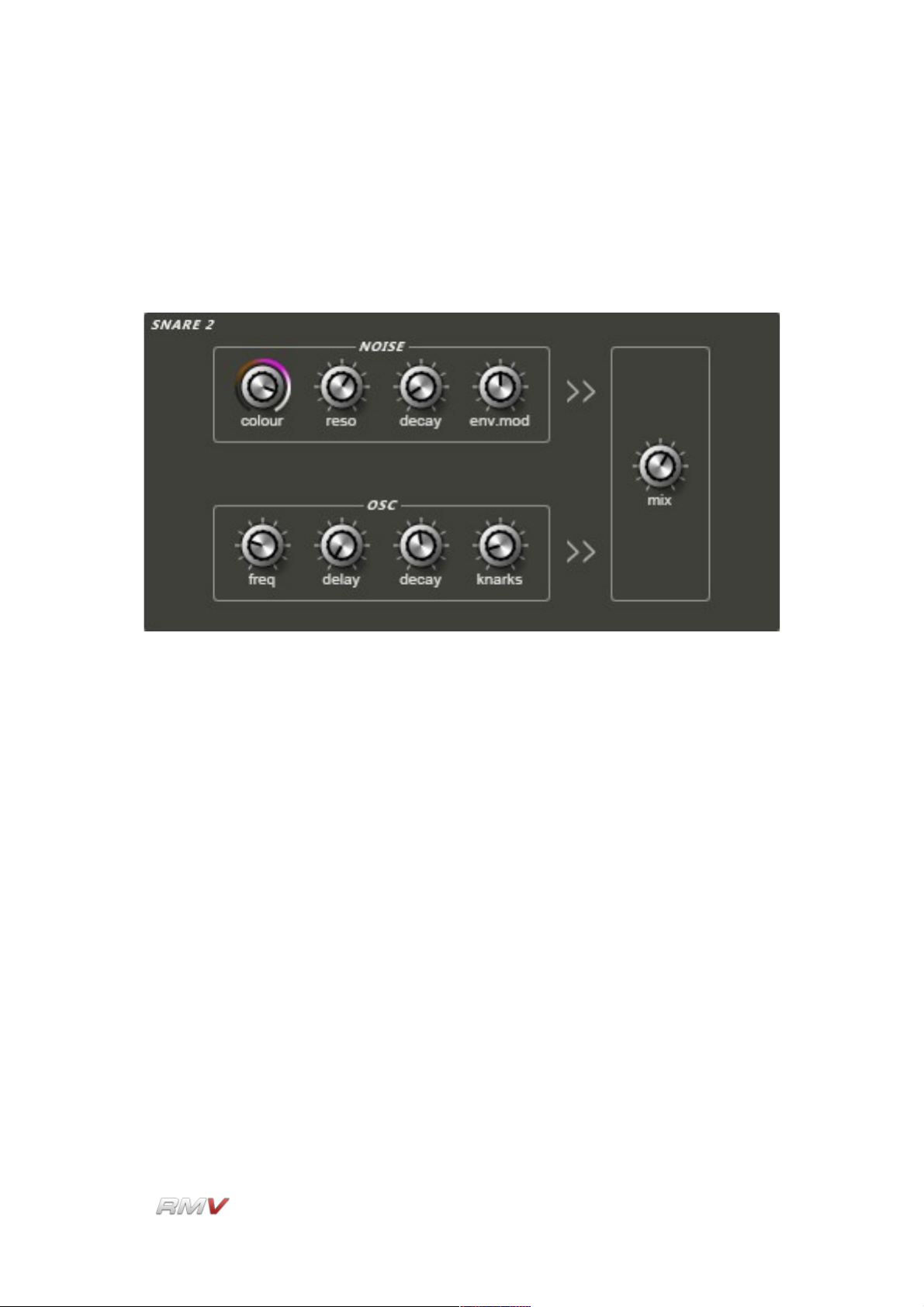
Snare 2
The Snare 2 module combines a noise oscillator and a pitched oscillator that incorporates
a specially designed "Knarks" control. The "Knarks" control adds a unique sound
(reminiscent of the word "knarks") to the module's output. The "Knarks" effect is created by
crossmodulating the noise source and the oscillator.
The Snare 2 Percussion Synthesis module contains the following controls:
The Mix control is used to adjust the mix of the "Knarks" oscillator and the Noise Oscillator.
The Decay control is used to determine the rate at which the mixed sound decays.
Noise Colour: The Noise Colour control setting determines the frequency spectrum
of the noise oscillator's output. As it is crossmodulated with the
pitched oscillator, the setting of this control directly affects the sound
of the output.
Noise (Res)onance: The Noise Res(onance) control is used to set the amount of
emphasis around the noise oscillator's cutoff frequency. Higher
settings create a more pronounced peak in the signal while lower
settings produce a flatter response.
Noise Decay: The Noise Decay (Time) control determines how fast the noise
oscillator output decays after it is triggered. The decay time increases
as the dial is turned in a clockwise direction.
Noise Env(elope) Mod(ulation): The Noise Env(elope) Mod(ulation) control is used to
set the degree to which the noise oscillator's filter cutoff frequency is
modulated by the oscillator's amplitude envelope.
LinPlug Reference Manual 5.0.1 40
Page 41

Audio Modules
Osc(illator) Freq(uency): The setting of the Osc(illator) Freq(uency) control determines
the drum's fundamental frequency. The frequency changes from low
to high as the control is turned in a clockwise direction. This control
interacts with the Tune control on the associated Pad.
Osc(illator) Delay (Time): The Osc(illator) Delay (Time) control is used to set the delay
time between the triggering of the oscillator and the time it starts
playing. The delay time increases as the dial is turned in a clockwise
direction.
Osc(illator) Decay (Time): The Osc(illator) Decay (Time) control determines how fast the
pitched oscillator output decays after it is triggered. The decay time
increases as the dial is turned in a clockwise direction.
Osc(illator) Knarks: The Osc(illator) "Knarks" control varies the amount of
crossmodulation between the pitched and noise oscillators.
Mix: The Mix control is used to set the relative amounts of the pitched
oscillator and the noise oscillator in the output signal. Rotating the
control in the anti-clockwise direction increases the proportion of
pitched oscillator signal in the output, while rotating the control in the
clockwise direction increases the proportion of noise signal in the
output.
LinPlug Reference Manual 5.0.1 41
Page 42
Audio Modules
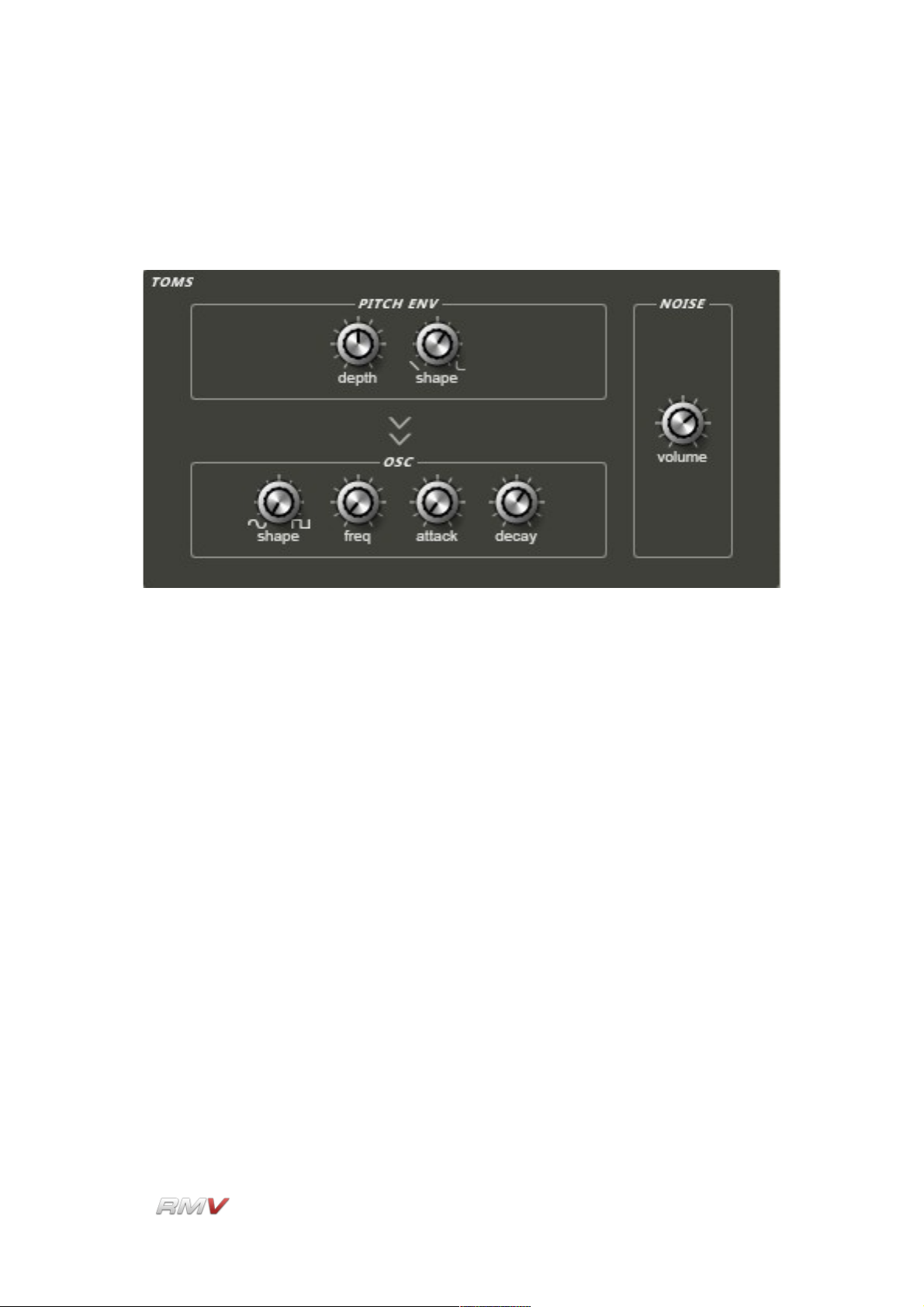
Tom
The Tom module employs a pitched oscillator and a noise oscillator to create the
characteristic sound of a tom.
The Tom Percussion Synthesis module contains the following controls:
Pitch Env(elope) Depth: The Pitch Env(elope) Depth control determines the extent to
which the drum's pitch is controlled by the pitch envelope.
Pitch Env(elope) Shape: The Pitch Env(elope) Shape control is used to set the shape of
the drum's pitch envelope. This can range from linear to extreme
exponential.
Osc(illator) Shape: The Osc(illator) Shape control is used to set the shape of the
oscillator waveform. When turned fully anti-clockwise the oscillator
produces a sine wave, while when turned fully clockwise the
oscillator produces a pulse wave.
Osc(illator) Freq(uency): The setting of the Osc(illator) Freq(uency) control determines
the drum's fundamental frequency. The frequency changes from low
to high as the dial is turned in a clockwise direction. This control
interacts with the Tune control on the associated Pad.
Osc(illator) Attack (Time): The Osc(illator) Attack (Time) control is used to set the drum
oscillator's attack time. Setting this control to a high value delays the
onset of the drum waveform, creating damping or muffling effects.
LinPlug Reference Manual 5.0.1 42
Page 43

Audio Modules
Osc(illator) Decay (Time): The Osc(illator) Decay (Time) control determines how fast the
sound decays after it is triggered. The decay time increases as the
dial is turned in a clockwise direction.
Noise Volume: The Noise Volume control is used to determine how much noise is
mixed with the output of the pitched oscillator.
LinPlug Reference Manual 5.0.1 43
Page 44

Audio Modules
Open Hat/Closed Hat
The Open/Closed (Hi)hat module employs a noise oscillator and a filter to create open and
closed hihat sounds.
Note that a similar algorithm is used for both the Open and Closed (Hi) hat sounds
however the parameter ranges for each control are different in each case. The
Open/Closed Hat Percussion Synthesis module contains the following controls:
Osc(illator) Colour: The Osc(illator) Colour control is used to set the frequency spectrum
of the oscillator's output.
Osc(illator) Decay (Time): The Osc(illator) Decay (Time) control determines how fast the
oscillator decays after it is triggered. The decay time increases as the
control is turned in a clockwise direction.
Osc(illator) (Decay) Shape: The Osc(illator) (Decay) Shape control is used to set the
shape of the oscillator's decay envelope. The shape of the envelope
segment can range from extreme negative exponential to extreme
positive exponential. At the midpoint the decay envelope shape is
linear.
Filter Reso(nance): The Filter Res(onance) control is used to set the amount of filter
resonance. This in turn, emphasizes a specific frequency depending
on the setting of the Osc(illator) Colour control and the Filter
Env(elope) Depth control.
Filter Env(elope) Depth: The setting of the Filter Env(elope) Depth control determines
LinPlug Reference Manual 5.0.1 44
Page 45

Audio Modules
the degree to which the filter is closed while the sound decays (when
turned fully clockwise) or open while the sound decays (when turned
fully anti-clockwise).
Filter Thin: The Filter Thin control is used to make the hihats sound thinner and
sharper, reducing the "body" of their sound.
LinPlug Reference Manual 5.0.1 45
Page 46

Audio Modules
Ride Cymb. (Cymbal)
The Ride Cymb. (Cymbal) module combines a pitched oscillator and a noise oscillator.
The Ride Cymb. (Cymbal) Percussion Synthesis module contains the following controls:
Osc(illator) Freq(uency): The setting of the Osc(illator) Freq(uency) control determines
the sound's fundamental frequency. The frequency changes from low
to high as the dial is turned in a clockwise direction. Note that this
control interacts with the Tune control on the associated Pad.
Osc(illator) Harmonic: The Osc(illator) Harmonic control is used to set the harmonic
content of the oscillator. In general, as the control is turned
clockwise, the sound becomes brighter.
Osc(illator) Decay (Time): The Oscillator Decay (Time) control determines the rate at
which the pitched part of the cymbal sound decays. Turning the
control in a clockwise direction increases the pitched oscillator decay
time.
Noise Colour: The Noise Colour control is used to set the frequency spectrum of
the noise oscillator.
Noise Decay (Time): The Noise Decay (Time) control is used to set the rate at which the
noise part of the cymbal sound decays. Turning the control in a
clockwise direction increases the noise oscillator decay time.
Modulation Freq(uency): The Modulation Freq(uency) control is used to set the
LinPlug Reference Manual 5.0.1 46
Page 47

Audio Modules
frequency at which the cymbal oscillator's pitch and amplitude
envelopes are modulated. This parameter adds life and movement to
the cymbal's sound, however the effect is intentionally quite subtle.
Modulation Depth: The Modulation Depth control sets the depth to which the cymbal
oscillator's pitch and amplitude envelopes are modulated. This
parameter adds life and movement to the cymbal's sound, however
the effect is intentionally quite subtle.
Modulation Pitch Env(elope): The Modulation Pitch Env(elope) control is used to add
a decay stage to the oscillator's pitch envelope.
Mix: The Mix control adjusts the mix of pitched sound and noise in the
module's output. Rotating the control in the anti-clockwise direction
increases the proportion of pitched oscillator signal in the output,
while rotating the control in the clockwise direction increases the
proportion of noise signal in the output.
LinPlug Reference Manual 5.0.1 47
Page 48
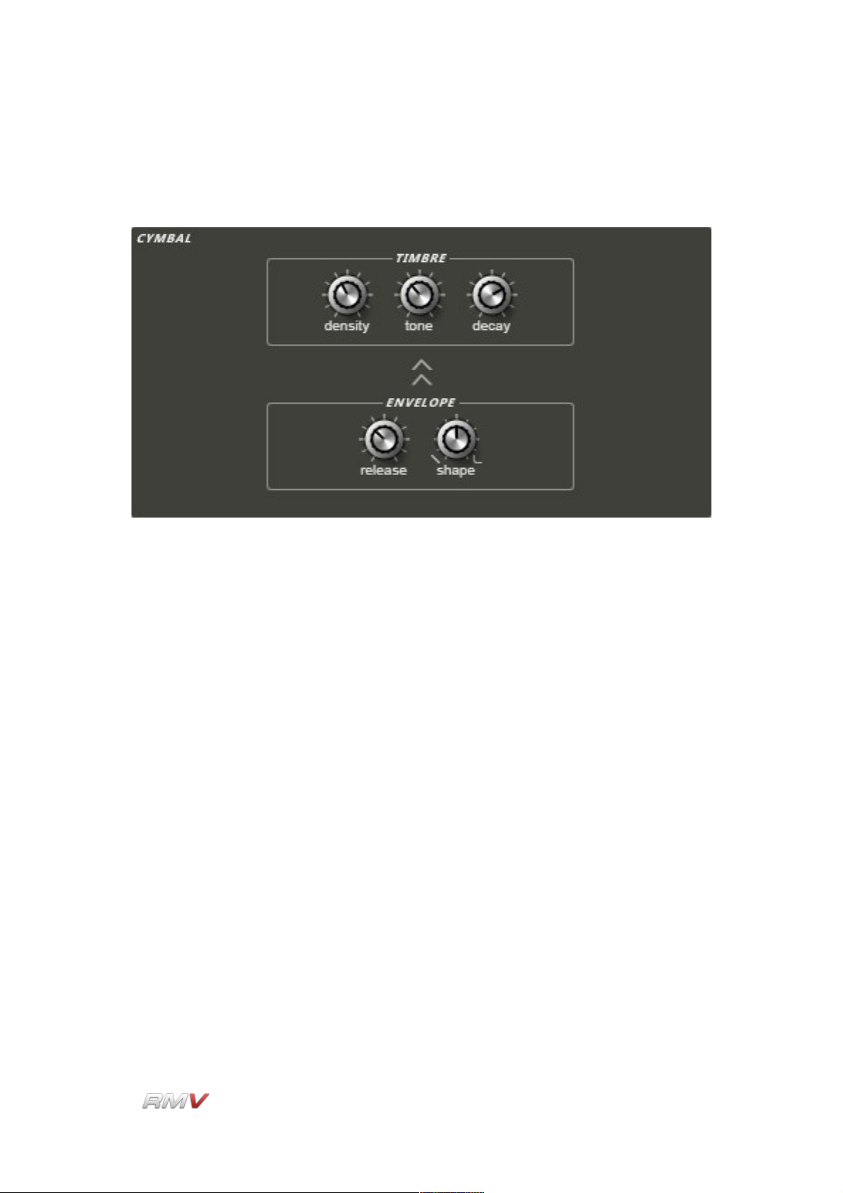
Audio Modules
Cymbal 2
The Cymbal 2 module employs a noise oscillator to produce the sound of a crash cymbal.
The Cymbal 2 Percussion Synthesis module contains the following controls:
Timbre Density: The setting of the Timbre Density control determines the richness of
the cymbal's sound. Rotating this control in a clockwise direction
increases the number of oscillators involved in sound production from
three to fifteen. As a result, higher settings produce a richer sound.
Timbre Tone: The Timbre Tone control is used to control the cymbal's overall
timbre. This can range from dark to light depending upon the setting.
Timbre Decay: The Timbre Decay control is used to determine how the cymbal's
timbre changes as its signal decays. As the dial is turned clockwise,
the cymbal's timbre changes more slowly as the signal decays.
Env(elope) Release (Time): The Env(elope) Release (Time) control is used to set the
cymbal's amplitude envelope release time. As the control is turned in
a clockwise direction, the release time increases.
Env(elope) Shape: The Env(elope) Shape control is used to set the shape of the decay
portion of the instrument's amplitude envelope. When the control is
turned in an anti-clockwise direction the envelope shape becomes
linear. As the control is turned in a clockwise direction, the envelope
shape becomes exponential.
LinPlug Reference Manual 5.0.1 48
Page 49
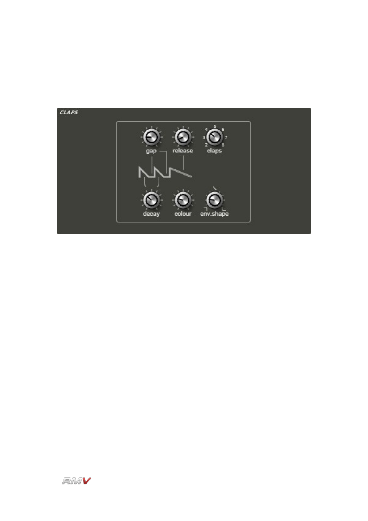
Audio Modules
Claps
The Claps module uses short noise bursts and a longer noise tail to create a characteristic
electronic "clap" sound.
The Claps module contains the following controls:
Gap: The Gap control is used to set the length of time between the noise
bursts that produce the "clap" sound. Rotating the control in a
clockwise direction increases the length of time between the noise
bursts.
Release: The Release control is used to determine the duration of the release
portion of the clap signal's noise tail. Rotating the control in a
clockwise direction increases the duration of the release portion of
the clap's noise signal.
Claps: The Claps control is used to set the number of claps produced by the
Clap module. Setting this to higher values increases the number of
claps and thickens the sound.
Decay: The Decay control is used to set the rate at which the single noise
bursts decay to silence. Rotating the control in a clockwise direction
increases the decay time of each noise burst.
Colour: The Colour control is used to set the frequency spectrum of the clap
noise oscillator. Rotating the control is a clockwise direction
increases the spectral content of the clap noise oscillator.
LinPlug Reference Manual 5.0.1 49
Page 50

Audio Modules
Env(elope) Shape: The Envelope Shape control is used to set the shape of a single
clap's decay and release envelope segments. When the control is
turned in an anti-clockwise direction the shape of the envelope
segments becomes linear. As the control is turned in a clockwise
direction, the shape of the envelope segments becomes exponential.
LinPlug Reference Manual 5.0.1 50
Page 51
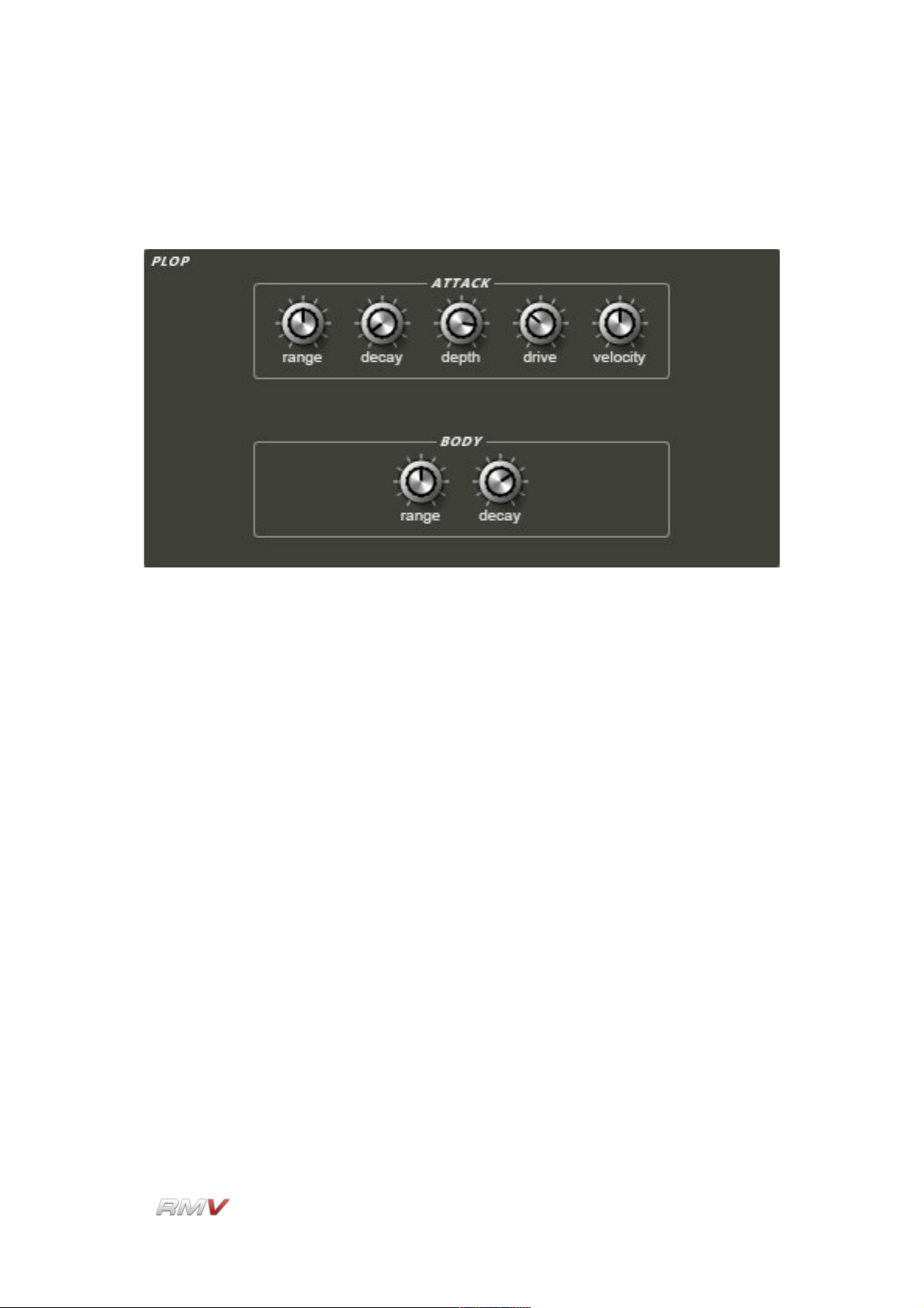
Audio Modules
Plop
The Plop module uses Frequency Modulation to create a unique "plop" sound.
The Plop module contains the following controls:
Attack Range: The Attack Range control is used to set the frequency range of the
attack portion of the sound. The sound's Attack Range is adjusted
relative to the Body Range setting.
Attack Decay: The Attack Decay control is used to set the rate at which the attack
part of the plop sound decays. Rotating the control in a clockwise
direction increases the decay time of the plop sound's attack.
Attack Depth: The Attack Depth control is used to set the intensity of the attack
portion of the plop sound. This can be used to make the sound more
aggressive. Rotating the control in a clockwise direction increases
the effect and makes the sound “harder”.
Attack Drive: The Attack Drive control is used to make the attack part of the sound
harder and more aggressive. Rotating the control in a clockwise
direction increases the effect and makes the sound “harder”.
Attack Velocity: The Attack Velocity enables trigger velocity to control the intensity of
the attack part of the sound. Rotating the control in a clockwise
direction increases the effect and makes the module more
responsive to the instrument's trigger velocity.
LinPlug Reference Manual 5.0.1 51
Page 52

Audio Modules
Body Range: The Body Range control is used to set the range (frequency) of the
body sound that follows the attack part of the module's sound.
Rotating the control in a clockwise direction increases the frequency
range of the body portion of the module's sound.
Body Decay: The Body Decay control is used to set the rate at which the body
sound decays to silence. Rotating the control in a clockwise direction
increases the decay time of the body portion of the module's sound.
LinPlug Reference Manual 5.0.1 52
Page 53

Audio Modules
Drum Synth
The modules described above are designed to produce a specific type of percussion
sound. Because of this they do not offer certain parameters, and the parameters that are
available are limited to specific ranges. The Drum Synth module is unlike these modules
as it has been designed as a “universal drum synthesizer”. This means that it has features
not found in any of the other synthesis modules. The Drum Synth module is based on one
conventional oscillator and one noise oscillator. Each oscillator can be delayed relative to
the other, and can be modulated using an envelope and a fast LFO at the same time. The
modulation controls are unusual in that they have extremely large depth and time ranges.
The Drum Synth module contains the following controls:
Oscillator Wave: The Oscillator Wave control is used to set the oscillator's waveform.
Three waveforms are available: Sawtooth, Triangle and Sine.
Oscillator Freq(uency): The Oscillator Freq(uency) control is used to set the frequency of
the oscillator. The available range is 20 Hz to 20000 Hz.
Oscillator Phase: The Oscillator Phase control is used to set the point in the waveform
cycle at which the wave starts when the oscillator is triggered. The
available range is 0 degrees to 360 degrees which represent one
complete waveform cycle.
Oscillator Delay: The Oscillator Delay control is used to set the delay time between the
triggering of the oscillator and the time it starts playing.
LinPlug Reference Manual 5.0.1 53
Page 54

Audio Modules
Oscillator Decay: The Oscillator Decay control is used to set the duration of the
oscillator's decay envelope.
Pitch Modulation Env(elope) Amt (Amount): The Pitch Modulation Env(elope) Amt
(Amount) control is used to set the degree to which the Drum Synth's
pitch is modulated by the module's internal envelope. Turning the
control in an anti-clockwise direction causes the modulation to start
from below the pitch of the oscillator. Turning the control in a
clockwise direction causes the modulation to start from above the
pitch of the oscillator.
Pitch Modulation Env(elope) Dec(ay): The Pitch Modulation Env(elope) Dec(ay) control
is used to set the time taken for the pitch of the Drum Synth's
oscillator to move from its initial modulation value to the final
oscillator value. The available range is 0.1 ms to 10 seconds.
Pitch Modulation LFO Type: The Pitch Modulation LFO Type control is used to select the
waveform used by the Drum Synth's internal LFO. Four waveforms
are available: sine, triangle, sawtooth, and sample and hold.
Pitch Modulation LFO Mod(ulation) Amt (Amount): The Pitch Modulation LFO Mod(ulation)
Amt (Amount) control is used to set the degree to which the Drum
Synth's internal LFO modulates the pitch of the Drum Synth's
oscillator. The available range is +- 8 octaves.
Pitch Modulation LFO Mod(ulation) Freq (uency): The Pitch Modulation LFO Mod(ulation)
Freq (uency) control is used to set the degree to which the Drum
Synth's internal LFO modulates the frequency of the Drum Synth's
oscillator. The available range is 0.01 Hz to 4400 Hz.
Noise Cut: The Noise Cut(off) control is used to set the cutoff frequency of the
Drum Synth's noise oscillators internal filter.
Noise Reso(Resonance): The Noise Reso(nance) control is used to set the amount of
resonance present in the noise oscillator's internal filter.
Noise Delay: The Noise Delay control is used to set the delay time between the
triggering of the noise oscillator and the start of it playing.
Noise Decay: The Noise Decay control is used to set the duration of the noise
oscillator's decay envelope.
Noise Attack: The Noise Attack control is used to set the time taken for the noise
oscillator to reach its full output value once it has been triggered.
LinPlug Reference Manual 5.0.1 54
Page 55

Audio Modules
Noise Dec(ay) Cur(ve): The Noise Dec(ay) Cur(ve) control is used to set the shape of the
noise oscillator's decay envelope. Turning the control in an anticlockwise direction makes the curve more concave which means that
the envelope value decreases more rapidly at the start, while turning
the control in a clockwise direction makes the control more convex
which means that the envelope value decreases more slowly at the
start.
Mix: The Drum Synth's Mix control is used to set the balance between the
module's pitched oscillator and its noise oscillator. Turning the control
in an anti-clockwise direction increases the proportion of the pitched
oscillator in the output signal. Turning the control in a clockwise
direction increases the proportion of the noise oscillator in the output
signal. At the mid-point, the module's output is equally divided
between the two oscillators.
LinPlug Reference Manual 5.0.1 55
Page 56
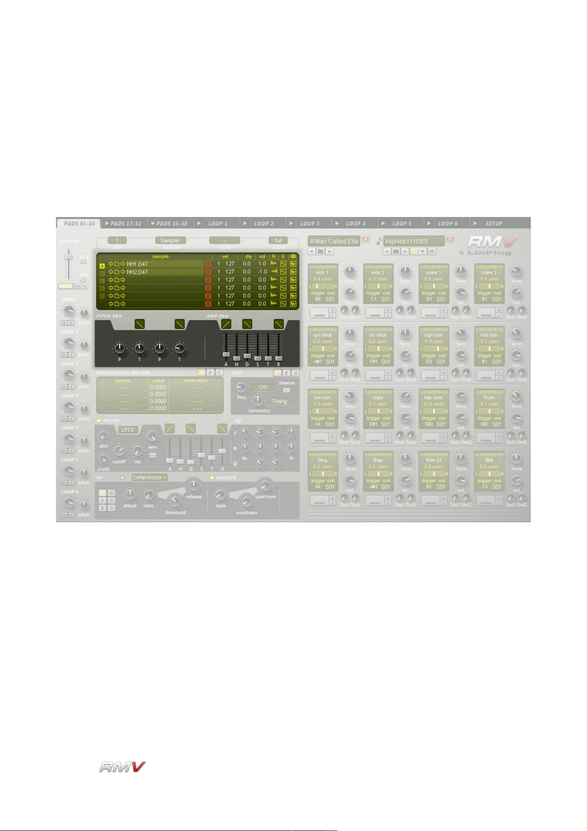
Audio Modules
Sampler Module
The RMV's Sampler module is used to load up to 30 Samples into an individual Pad, and
also to edit the playback parameters of Samples once they are loaded. This module is
made up of three separate components: The Sample Display, The Pitch Envelope and the
Amplitude Envelope. Note that the Filter Envelope parameters are also displayed in the
Sample module's Waveform view.
The RMV's Sample Display has two separate “views”. Table view displays a set of “Sample
Slots”, while Waveform view displays the Sample's waveform as well as the parameters of
the pitch, amplitude and filter envelopes that are applied to it. The RMV Sampler Module
also has three envelopes available for each Pad. The controls for these envelopes are
located below the Sample Display. The Pitch Envelope is located on the left, while the
Amplitude Envelope is located on the right. The Pitch Envelope is used to set the Pad's
various pitch parameters, while the Amplitude Envelope is use to set the Pad's amplitude
parameters. It's important to note that these envelopes apply to all of the Samples
currently loaded into the Pad. The Waveform Display also shows the current filter settings
for the Module. The parameters of the Filter Envelope are set using the controls found in
the RMV's Filter section.
LinPlug Reference Manual 5.0.1 56
Page 57

Audio Modules
Table View
The Table view consists of 30 "Sample Slots" divided into five groups of six slots into which
samples can be loaded. The Sample Display shows various parameters for the currentlyloaded Sample/s.
Selector: The Selector button array is located to the left of the main display. It
consists of five small square vertically-aligned buttons which allow a
choice of five screens (“A”, “B”,“C”, “D” and “E”) each of which
displays six sample "Slots". The first screen displays "Slots" one to
six. This is probably all that will be required for normal drum
instruments. However, if a multisampled instrument is being used, it
may be necessary to use more than six "Slots". In this case you can
switch to the second screen to see "Slots" seven to twelve and so on
up to "Slot" thirty on the fifth screen.
File: The File section consists of three controls: a "Browse Backwards"
button (left-pointing arrow icon), a "Directory" button (directory icon)
and a "Browse Forwards" button (right-pointing arrow icon). These
controls allow Samples from a particular directory to be loaded and
browsed. Clicking on the "Directory" button opens the Sample
Browser dialog which allows you to load Samples into the currently
active Drum Pad. The Sample Browser acts as a replacement for the
operating system file browser adding additional functions such as
Preview. The Sample Browser is described in more detail below.
Once a Sample has been loaded, the "Browse Backwards/Browse
Forwards" buttons on either side of the "Directory" button can be
used to navigate forwards or backwards within the currently selected
directory. This significantly reduces the time taken to locate and load
samples. The Sampler module currently supports .WAV, .AIF and
LinPlug's D4T file formats. The Sampler module can also load .REX
files however in this case, the playback of individual file slices is not
supported.
Sample: The Sample parameter displays the name of the currently loaded
LinPlug Reference Manual 5.0.1 57
Page 58

Audio Modules
sample. Note that the name of the currently active Sample Slot is
highlighted.
Clear: To the right of the sample's name is the "Clear" button ( "X" icon).
Clicking on this button removes the currently loaded sample from the
selected slot.
Velocity: The Velocity setting determines the velocity range in which a
particular sample is triggered. Setting different velocity ranges for
individual samples allows you to create expressive multisampled
instruments that respond dynamically to MIDI input. For example,
imagine that you have three samples assigned to a single key. If you
set the sample velocities so that sample 1 is triggered in the 1 to 59
velocity range, and sample 2 is triggered in the 60 to 89 velocity
range you have what is known as hard velocity switching. If however,
you overlap the two samples' velocities (for example, sample 1 is
triggered in the 1 to 80 velocity range while sample 2 is triggered in
the 50 to 100 velocity range) you create what is known as a velocity
crossfade. In the crossover region (50 to 80) the volume of one
sample is successively reduced, while the volume of the other
sample is successively increased until only one sample is heard.
Clicking on the “Vel” label open a menu which allows you to
automatically assign velocity regions to the currently loaded samples.
This is useful when you build kits from scratch and have loaded a
number of samples to a pad to create a multisampled sound. In the
menu “Up” assigns the lowest velocity range to the first sample while
“Dw” (Down) assigns the highest velocity range to the first sample.
The “Lin” and “Log” sub entries refer to a linear or a logarithmic
assignment (where the lower ranges are not as detailled than the
higher velocity ranges).
Delay: The Delay setting determines the position in the sample at which
playback begins. This is often referred to as Offset or Shift and
allows you to start the sample at a position after the normal starting
point. Offsetting the starting point of a sample is useful when layering
sounds or when the attack portion of a sample is too slow.
Vol: The Vol (Volume) setting adjusts the volume of samples. This
parameter is useful when the samples used in a multisampled
instrument have different volume levels. Adjusting the Vol setting
enables multisamples to be matched to each other thereby producing
a more realistic Instrument. The Vol setting can also be used to
adjust the volume of individual samples within layered Instruments in
order to make them sound smoother.
LinPlug Reference Manual 5.0.1 58
Page 59
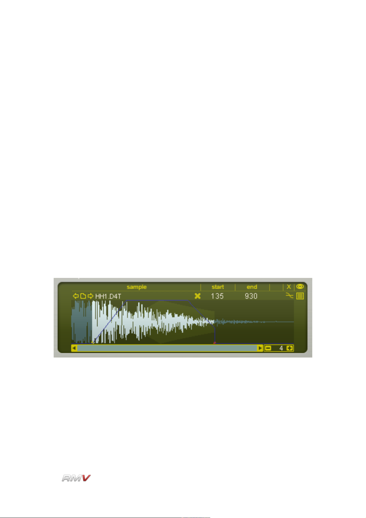
Audio Modules
R: The R or "reverse" setting determines the direction in which the
sample is played back. Normally, samples play from start to end.
However, by clicking on the R button sample playback is reversed.
Edit: The Edit button is used to open the Sample Editor menu. This menu
enables the currently loaded sample to be edited in an external
editor. The editor that is used is specified in the Sample Editor control
which is located in the RMV's Setup panel (see the Setup Panel
section of this guide for more information about the RMV's Setup
Panel). The Sample Editor menu contains 3 items: Edit in external
editor, Edit copy in external editor, and Reload. The first menu option
opens the Sample in an external editor. The second menu option
opens a copy of the Sample in an external editor, while the third
menu option reloads the Sample from the external editor.
View: Clicking on the "Waveform" symbol at the far right of each sample
slot (assuming that a sample is loaded into the "Slot") changes the
display from "Table" mode to "Waveform" mode and vice-versa.
Waveform View
Waveform mode enables several sample playback parameters to be set. Once in
Waveform mode, the top line of the Sample Playback Editor displays the currently loaded
sample's various parameters.
The Sampler's Waveform view also shows a Sample's Pitch, Amplitude and Filter envelope
settings which greatly assists in setting their various values.
The Waveform display's magnification is set using the plus/minus buttons at the bottom
right of the display. The number in the middle of the plus/minus buttons shows the number
of samples compressed into a single pixel's width. For example, if the magnification is 1,
then one sample is displayed per pixel. If the display shows 16, then 16 samples are
compressed into a single pixel thus creating a display of the waveform that is compressed
16 times. The scrollbar at the bottom of the display allows you to scroll the sample when it
LinPlug Reference Manual 5.0.1 59
Page 60

Audio Modules
is too long to be displayed in the window. This, of course, depends on the current
magnification setting.
Sample: The Sample parameter displays the name of the currently loaded
sample. Note that the name of the currently active Sample Slot is
highlighted.
Clear: To the right of the sample's name is the "Clear" button ( "X" icon).
Clicking on this button allows you to remove the currently loaded
sample from the selected slot.
Sample Start: The point in the file at which playback starts can be set in two
different ways. The first way is be dragging the start point cursor to
the required position. The second way is by setting the “Start” control
to the desired numeric value (in samples).
Sample End: The point in the file at which playback ends can be set in two
different ways. The first way is be dragging the end point cursor to
the required position. The second way is by setting the “End” control
to the desired numeric value (in samples).
Snap to Zero Crossing: The setting of the Snapping Zero Crossing button determines
whether sample start and end cursors automatically “snap” to the
nearest zero crossing point or not. When switched on, (the default
setting) sample start and end cursors can only be set to a zerocrossing point within the sample. This produces a smoother, more
natural sound. When the Zero Crossing button is switched off,
sample start and end cursors can be placed at any point within the
waveform. This can be used to produce aggressive or "clicky"
sounds.
View: Clicking on the "View" symbol at the far right of each sample slot
(assuming that a sample is loaded into the "Slot") changes the
display from "Table" mode to "Waveform" mode and vice-versa.
Pitch Envelope, Amplitude Envelope and Filter Envelope
The Waveform view shows the sample's waveform, along with the Pad's amplitude, and
pitch envelopes. The amplitude envelope is shown as a grey envelope behind the sample.
The pitch envelope is calculated directly into the sample and is not shown as a separate
envelope. If the filter is on, its envelope is shown as a blue line.
LinPlug Reference Manual 5.0.1 60
Page 61

Audio Modules
It should be noted that the length of the sustain phase of each envelope cannot be
displayed exactly as it depends on when a Note-Off message is received. It is shown in
the display merely as an example. It should also be noted that in order to see the entire
amplitude and filter envelopes, the magnification setting needs to be set so that the whole
sample waveform is visible in the display.
P(itch): P(itch): The first Pitch slider determines the pitch envelope's initial
value. For example, a value of three means the envelope begins
playing back the sample 3 semitones above its base pitch. The Pitch
slider can be set to a wide range of values; from +48 semitones (4
octaves up) to -48 semitones (4 octaves down).
T(ime): The first Time slider determines the length of time it takes for the
pitch envelope to move from the first pitch value (see above) to the
second pitch value (see below). For example, if the Time slider is set
to 0.100 seconds, the sample's pitch will move from the sample's first
pitch value to the sample's second pitch value within 100
milliseconds.
Envelope Shape: The Time slider has a corresponding “curve” control located above it
that is used to set the shape of the envelope segment. The shape of
the segment can range from extreme negative exponential to
extreme positive exponential. To adjust the “curve” setting, click on
the control and drag the cursor up or down. The change in the
LinPlug Reference Manual 5.0.1 61
Page 62

Audio Modules
curve's shape will be shown on the control.
P(itch): The second Pitch slider determines the pitch envelope's target value.
For example, a value of twelve means that after the first time period
has elapsed (see above), the envelope changes the sample's pitch
by +12 semitones. The Pitch slider can be set to a wide range of
values; from +48 semitones (4 octaves up) to -48 semitones (4
octaves down).
T(ime): The second Time slider determines the length of time it takes for the
pitch envelope to move from the second pitch value (see above)
back to the sample's base pitch. For example, if the Time slider is set
to 0.100 seconds, the sample's pitch will move from the value set by
the Pitch slider to the sample's base frequency within 100
milliseconds.
Envelope Shape: The second Time slider has a corresponding “curve” control located
above it that is used to set the shape of the envelope segment. The
shape of the segment can range from extreme negative exponential
to extreme positive exponential. To adjust the “curve” setting, click on
the control and drag the cursor up or down. The change in the
curve's shape will be shown on the control.
Amplitude Envelope
A(ttack): The Attack dial determines the length of time it takes for the
amplitude envelope to reach the full envelope depth. For example, if
the Attack slider is set to 0.100 seconds, the sample's amplitude will
move from zero to full volume within 100 milliseconds.
Attack Envelope Shape: The Attack dial has a corresponding “curve” control located
above it that is used to set the shape of the envelope segment. The
shape of the segment can range from extreme negative exponential
to extreme positive exponential. To adjust the “curve” setting, click on
the control and drag the cursor up or down. The change in the
curve's shape will be shown on the control.
H(old): The Hold dial determines the length of time the amplitude envelope is
held at the maximum level.
D(ecay): The Decay dial determines the length of time that the amplitude
envelope takes to move from the Attack level to the Sustain level
after the Hold time has elapsed.
Decay Envelope Shape: The Decay dial has a corresponding “curve” control located
LinPlug Reference Manual 5.0.1 62
Page 63

Audio Modules
above it that is used to set the shape of the envelope segment. The
shape of the segment can range from extreme negative exponential
to extreme positive exponential. To adjust the “curve” setting, click on
the control and drag the cursor up or down. The change in the
curve's shape will be shown on the control.
S(ustain): The Sustain dial determines the level that the amplitude envelope is
held at during the Sustain portion of the envelope. It should be noted
that the length of the sustain phase cannot be displayed exactly as it
depends on when a Note-Off message is received. It is shown in the
display merely as an example.
T(ime) The T(ime) control is used to set a time value for the sustain segment
of the envelope. When set to its maximum value the sustain time is
infinite, that is, it is controlled by a MIDI NoteOff command. Setting
the T(ime) control to other values means that the sustain time is
independent of the MIDI NoteOff message.
R(elease): The Release dial determines the length of time that the amplitude
envelope takes to move from the Sustain level to 0 after a Note-Off
message has been received.
Release Envelope Shape: The Release dial has a corresponding “curve” control located
above it that is used to set the shape of the envelope segment. The
shape of the segment can range from extreme negative exponential
to extreme positive exponential. To adjust the “curve” setting, click on
the control and drag the cursor up or down. The change in the
curve's shape will be shown on the control.
The Filter Envelope settings for each Pad are displayed in the Sampler's Waveform view
as a blue line.
The Filter Envelope settings are
controlled using the RMV's Filter
controls which are found in the
Filter section. The RMV's Filter
section is described below.
LinPlug Reference Manual 5.0.1 63
Page 64
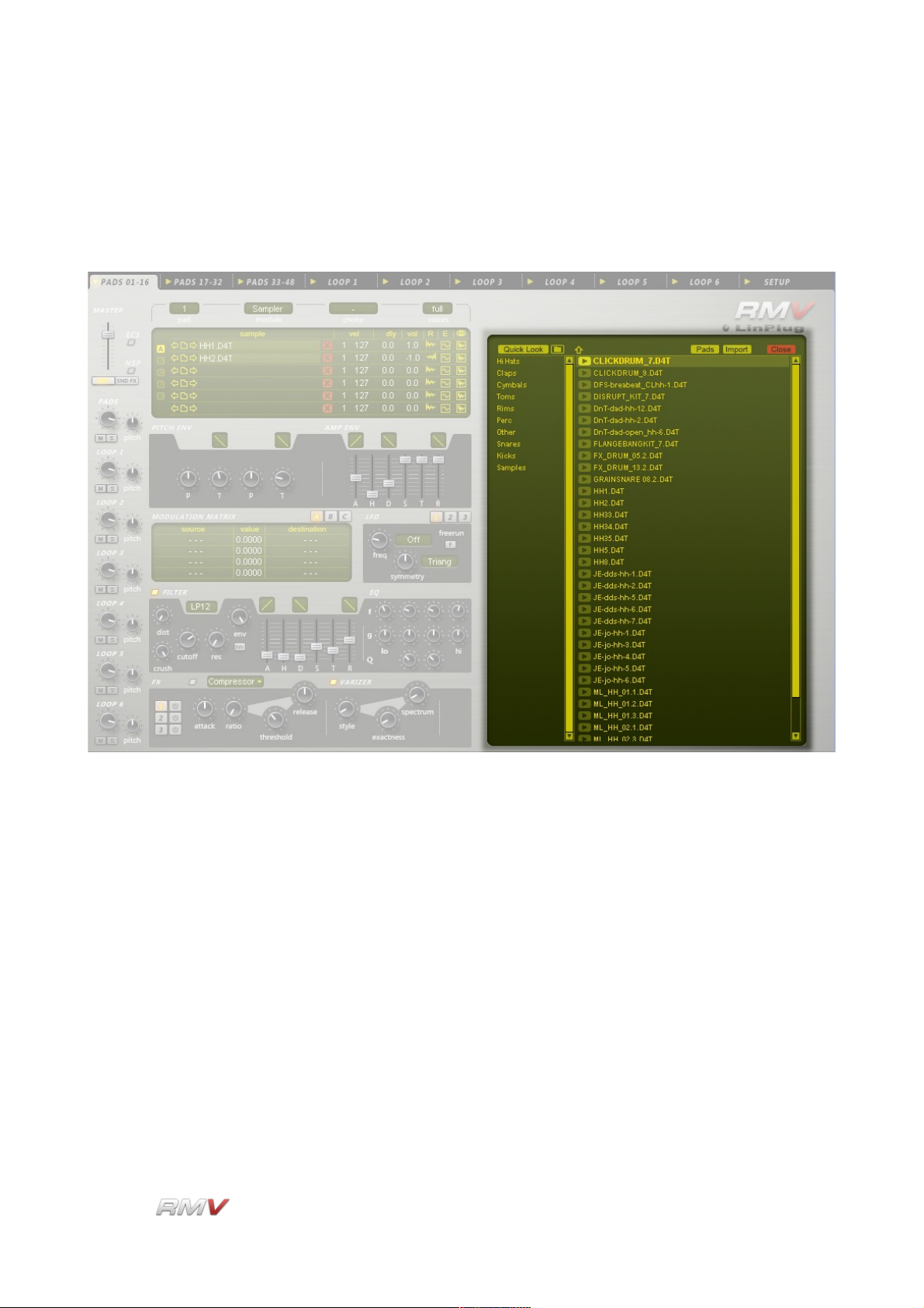
Audio Modules
Sample Browser
Clicking on the "Directory" button when the Sampler Module is in Table View mode opens
the Sample Browser.
The Sample Browser enables Samples to be loaded into the currently active Sample Slot.
LinPlug Reference Manual 5.0.1 64
Page 65

Audio Modules
The column on the left of the Sample Browser shows the current Sample Search Paths
(note that the Sample Search Paths can be set in the RMV's Setup Panel. See the Setup
Panel section of this guide for more information).
Quick Look: The Quick Look button opens a conventional file browser and can be
used for quickly loading samples without setting the path to the
directory in the Setup Panel.
Up Arrow: The Up Arrow button moves up one level within the file system's
directory hierarchy.
Once a directory containing samples or .REX files has been opened, the contents of the
directory are displayed in the File List in the centre of the Sample Browser. Clicking on a
sample or .REX file in the File List selects the file. Once selected, the file can be
previewed using the “Preview” button located to the left of the file's name.
LinPlug Reference Manual 5.0.1 65
Page 66

Audio Modules
Pads: The Pads button is used for loading multiple samples into successive
Pads. For example, if three samples are selected, clicking the Pads
button loads all three samples into the currently active Pad and the
next two Pads.
Import: The Import button is used to load the audio file into the Sampler's
currently active Slot.
Close: The Close button closes the Sample Browser.
LinPlug Reference Manual 5.0.1 66
Page 67
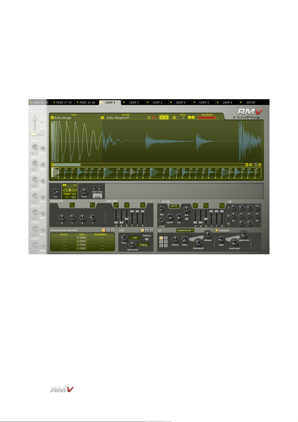
Loop Module
Loop Module
The RMV's Loop Module is used to load audio loops and samples into an individual Pad. It
can also be used to edit the playback parameters of loops and samples once they are
loaded. The RMV contains six identical Loop Modules.
Each Loop Module contains three sections: a Loop section, a Pad section, and a Signal
Processing section. A Loop Module's Loop section is used to load, edit and play audio
loops. A Loop Module's Pad section is similar to the Pad section that is used with the
RMV's Percussion Synthesis/Sampler modules, however there are several minor
differences which are described below. A Loop Module's Signal Processing section is the
same as that used by the Percussion Synthesis/Sampler modules. The Loop module's
Signal Processing section is described in the Signal Processing section of this guide. Each
Loop Module also has access to the RMV's Sample Browser and Loop Librarian. The
Sample Browser is described in the Sample Browser section of this guide, while the Loop
Librarian is described below.
The key feature of the Loop Module is that it can play back “sliced” files. A “sliced” file is a
file that has been “sliced” into segments, usually at the onset of a sound. “Sliced” files
have two advantages. Firstly, the tempo of a sliced file can be changed without the use of
time-stretching or pitch-shifting. This means that the presence of “artefacts” is minimised.
LinPlug Reference Manual 5.0.1 67
Page 68

Loop Module
Secondly, slices can be played back individually. This means that some slices can be
omitted from playback or that the order in which slices are played back can be changed
compared to that of the original file. Note that Loop editing is non-destructive; all changes
only affect the playback parameters of the audio loop.
The three sections of the RMV's Loop Module are described below.
LinPlug Reference Manual 5.0.1 68
Page 69
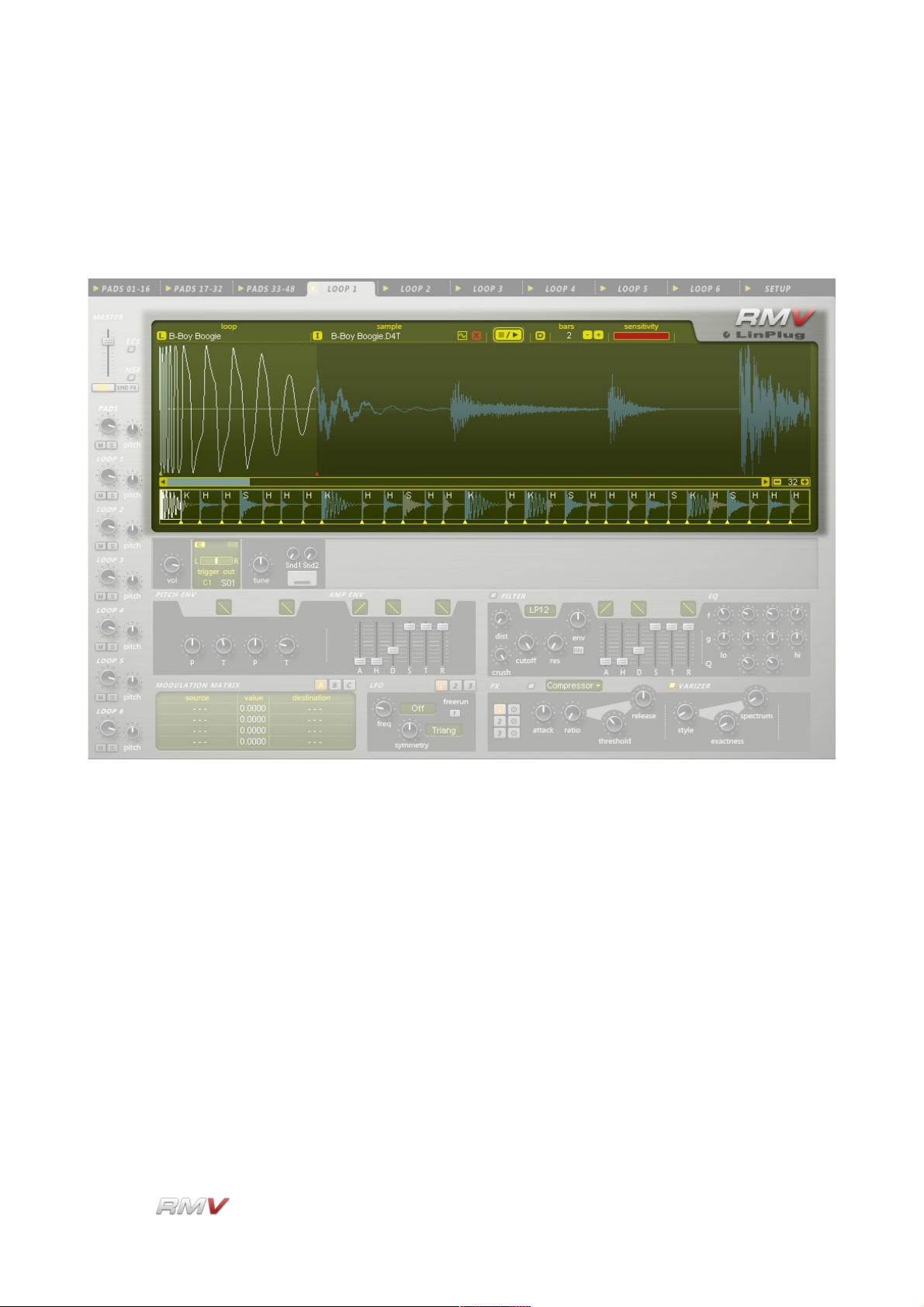
Loop Module
Loop Section
The RMV's Loop section is used to load, edit and play audio loops. The RMV supports files
in .REX format and can also load samples in .WAV, .AIF or LinPlug's D4T formats.
Files in .REX format already contain information regarding the slices in the file. This
information is used to slice the file when it is loaded. In the case of audio samples, the files
are automatically sliced when they are loaded. The Loop section contains two sections:
the Waveform section and the Slice section.
LinPlug Reference Manual 5.0.1 69
Page 70
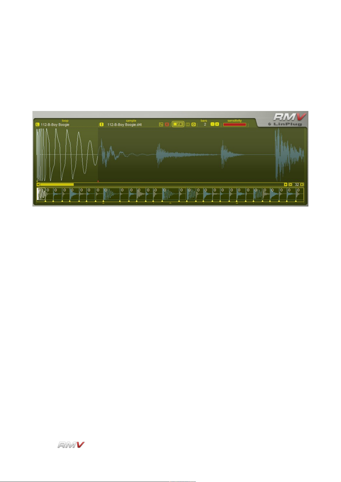
Loop Module
Waveform Section
The Loop Module's Waveform section displays the audio file's waveform as well as other
information such as the playback start and end points, and amplitude, pitch and filter
envelope shape. The Waveform section also contains several controls for working with
audio loops. These controls are described below.
L(oad): The (L)oad button is used to load Loops (in .REX format). The Load
button opens the Loop Librarian which enables Loops to be loaded
from either the RMV's internal Loop library or from any directory on
the user's computer. The Loop Librarian also enables Loops to be
saved, either to the RMV's internal Loop Library or to any directory
on the user's computer. See below for more information about the
Loop Librarian.
I(mport): Clicking on the Import ("I") button opens the Sample Browser which
allows Samples to be loaded into the Loop module. The Sample
Browser acts as a replacement for the operating system file browser
adding additional functions such as Preview.
Edit: The Edit button is used to open the Sample Editor menu. This menu
enables the currently loaded sample to be edited in an external
editor. The editor that is used is specified in the Sample Editor control
which is located in the RMV's Setup panel (see the Setup section of
this guide for more information about the RMV's Setup panel). The
Sample Editor menu contains 3 items: Edit in external editor, Edit
copy in external editor, and Reload. The first menu option opens the
Sample in an external editor. The second menu option opens a copy
of the Sample in an external editor, while the third menu option
reloads the Sample from the external editor.
Clear: To the right of the Edit button is the Clear button ( "X" icon). Clicking
LinPlug Reference Manual 5.0.1 70
Page 71

Loop Module
on this button removes the currently loaded Loop from the module.
Stop/Play: The Stop/Play buttons are used to control the playback of the current
Loop.
H The setting of the “H” Host Sync control determines whether or not
the module's internal MIDI data is used when the host application is
played (for more info refer to Appendix D).
D: The “D” Drag control is used for dragging a MIDI file containing the
timing information for all of the Slices to the host software. By doing
this, it is possible to play back individual slices while retaining the
timing information of the original file. This opens up a wide range of
creative possibilities including removing selected slices from
playback, or changing the order of slice playback.
Bars: When a Loop or a Sample is initially loaded it is automatically sliced,
and it is stretched or compressed so that it matches the tempo of the
host software. In some cases however, the length of the Sample or
Loop may not match the host software's tempo. For example, the file
might be one-and-a-half bars in length. In this case, it is possible to
set the duration of the Loop or Sample so that it matches a different
tempo division such as two or three bars. Available options are from
one to sixteen bars.
Sensitivity: The Sensitivity control is used to set the number of segments or
slices that a Loop or Sample is divided into. Setting the Sensitivity
control to its leftmost position sets it to its minimum value, which
means that the Loop or Sample is not sliced. Increasing the value of
the Sensitivity control increases the number of segments that the
Loop or Sample is divided into. The maximum number of slices that
an individual file can contain is 64. The number of slices that the
current Loop or Sample is divided into is shown in the RMV's Slice
section which is described below.
Waveform Display: The Waveform Display shows the currently loaded Loop or Sample.
The currently active slice is shown in white, while the remainder of
the Loop or Sample is shown in blue. It should also be noted that in
order to see the entire Loop or Sample, the magnification setting
needs to be set so that the whole sample waveform is visible in the
display. The magnification of the Waveform Display is set using the
Magnification control which is described below.
Slice Start Cursor: The Start Cursor for the currently active slice is shown as a yellow
triangular marker positioned at the left edge or the currently active
slice. The start position of the slice can be adjusted by dragging the
LinPlug Reference Manual 5.0.1 71
Page 72
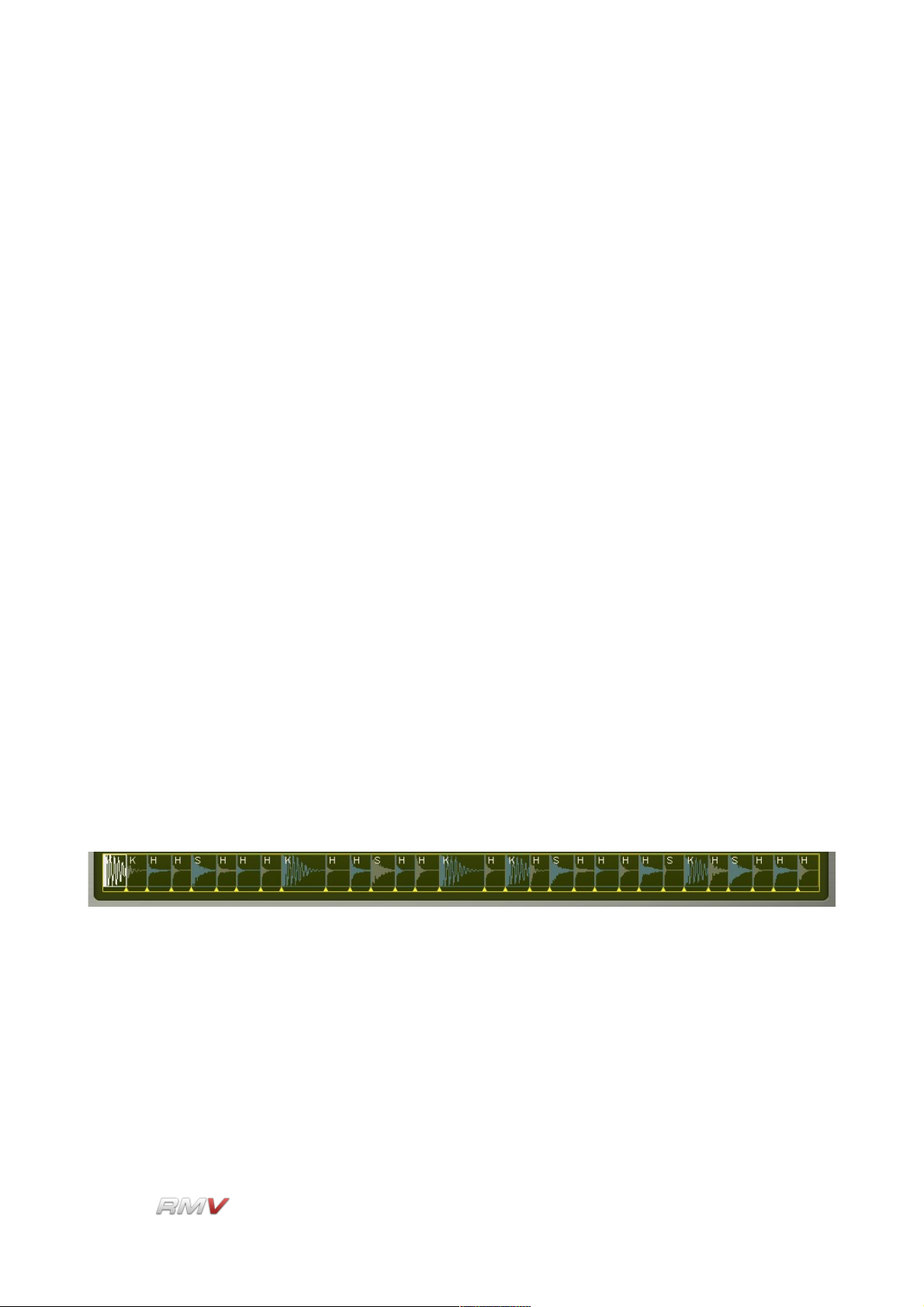
Loop Module
yellow triangular marker to the left or right. Note that the Start Cursor
can only be moved to the left as far as the start position of the
preceding slice, or to the right the position of the slice's end position.
Slice End Cursor: The End Cursor for the currently active slice is shown as a red
triangular marker positioned at the right edge or the currently active
slice. The end position of the slice can be adjusted by dragging the
red triangular marker to the left or right. Note that the End Cursor
can only be moved to the left as far as the start position of the slice,
or to the right as far as the end position of the following slice.
Magnification: The Waveform Display's magnification is set using the plus/minus
buttons at the bottom right of the display. The number in the middle
of the plus/minus buttons shows the number of samples compressed
into a single pixel's width. For example, if the magnification is 1, then
one sample is displayed per pixel. If the display shows 16, then 16
samples are compressed into a single pixel thus creating a display of
the waveform that is compressed 16 times. The scrollbar at the
bottom of the display allows you to scroll the sample when it is too
long to be displayed in the window. This, of course, depends on the
current magnification setting.
Slice Display
The Slice Display shows the entire Loop or Sample as a set of Slices. Each Slice has a
Start and End Cursor which is shown as a yellow triangular marker. The currently active
slice is shown in white, while the other slices are alternately coloured blue and olive-green.
Each Slice is also labelled according to its content. “K” refers to a Kick drum Slice, “S”
refers to a Snare drum slice, and “H” refers to HiHats and other percussion. Start and End
cursors for each Slice can be adjusted by dragging the triangular markers to the left or to
the right. Note that a cursor can only be moved as far as the preceding or following cursor.
Clicking on a Slice triggers the Slice and highlights it in the Waveform Display (described
above). The position at which the Slice is clicked determines the MIDI NoteOn velocity at
which the Slice is triggered. Clicking at the lower edge of the Slice triggers the Slice with a
low NoteOn velocity. The NoteOn velocity increases as the Slice is clicked at higher
positions.
LinPlug Reference Manual 5.0.1 72
Page 73

Loop Module
Pad Section
Each Loop module contains its own Pad section which is used for triggering the module's
currently active slice. Note that the Pad section changes position relative to the currently
active Slice, moving back and forth across the display.
The Pad in each of the RMV's six Loop
Modules is identical and consists of eleven
controls. described in detail below.
Vol(ume): The Vol(ume) control is used to set the output volume of the Pad.
The available range is -oo to +6 dB. The default value is -3 dB.
E (Edit): The E (Edit) Indicator (the small light at the top left of each Pad
section) shows the Pad that is currently active.
G (Group): Each of the RMV's Slices can be assigned to a Group. Assigning a
Slice to a Group enables all Slices in that Group to be edited using
LinPlug Reference Manual 5.0.1 73
Page 74

Loop Module
the controls of a single Slice. To set a Slice to a Group, click and drag
on the G (Group) button until the desired Group is displayed. Ten
Groups are available. Note that Group editing is relative which
means that if the value of one control in a Group is changed, the
other controls in the Group are changed by the same amount. They
are not set to the same value as the first control.
Attention: to change all Slicess in a Group, use the right mouse
button. With the left mouse button you only change the current Slice,
even when it has been assigned to a group!
Data Display: Each Pad has its own Data Display that shows the value of the
parameter currently being edited. For example, if the value of the
Amplitude Envelope's Attack Time is changed, the value is displayed
in the current Pad's Data Display.
Pan: The Pan control is used to set the stereo position of the Pad's output
and is located below the Pad's Data Display. The Pan control has a
range of 1.00 L to 1.00 R. A setting of "C" places the output in the
centre of the stereo field. Note that if the Pad's output is set to a
mono destination the Pan control has no effect.
Trigger (Note): The Trigger (Note) sets the MIDI note that triggers the Pad.
Out(put): The Out(put) control is used to set the output destination of the Pad.
Available destinations depend upon the instrument's current audio
output settings which are shown on the RMV's Setup Panel (for more
information about the RMV's Setup Panel, see below). Note that all
stereo outputs are listed first, followed by all of the mono outputs.
Trigger Button: The Trigger button allows the Pad to be played using the mouse,
which in turn, triggers the currently active Slice. To activate the
Trigger button click the mouse on the button. If Pad Velocity is
enabled on the RMV's Setup Panel (see below for more information
about the RMV's Setup Panel), the Pad becomes velocity-sensitive.
In this case, as the cursor is moved from left to right over the Trigger
button, the trigger velocity increases. In other words, clicking on the
left of the button triggers the Pad at lower velocities than clicking on
the right of the Pad. The Activity Indicator shows that the Pad has
been triggered. It stays lit until the Pad has finished playing.
Tune: The Tune control sets the Pad's tuning. The available range is +- 24
semitones in 10 cent steps.
Snd1 Amount: Each Pad can send its output to the Effects Racks in the RMV's Send
Effects section (see the Send Effects section of this manual for more
information about the RMV's Send Effects). The percentage of the
LinPlug Reference Manual 5.0.1 74
Page 75

Loop Module
signal sent to the Effects Rack selected using the Snd1 Destination
control is set using the Snd1 Amount control.
Snd1 Destination: The Snd1 Destination control is used to set the destination of a Pad's
first Effects Send. Three destinations, Snd1, Snd2 and Snd3 are
available. Each corresponds to one of the RMV's three Send Effects
Racks. Note that only one destination is active at a time.
Snd2 : Each Pad can send its output to the Effects Racks in the RMV's Send
Effects section (see the Send Effects section of this manual for more
information about the RMV's Send Effects). The percentage of the
signal sent to the Effects Rack selected using the Snd2 Destination
control is set using the Snd2 Amount control.
Snd2 Destination: The Snd2 Destination control is used to set the destination of a Pad's
second Effects Send. Three destinations, Snd1, Snd2 and Snd3 are
available. Each corresponds to one of the RMV's three Send Effects
Racks. Note that only one destination is active at a time.
LinPlug Reference Manual 5.0.1 75
Page 76

Loop Module
Signal Path
The Signal Path of a Loop module is identical to that of the RMV's other Modules. The
signal path of the audio output of a Loop module is described in the Signal Path section of
this guide.
LinPlug Reference Manual 5.0.1 76
Page 77

Loop Module
Loop Librarian
The RMV can load and save data in a variety of different formats. One of these formats is
a Loop file. A Loop file contains audio data as well as metadata describing the onset points
of the sounds contained within the file. The RMV incorporates a Loop Librarian which is
used to search for, load and save Loop files in .REX format. The Loop Librarian is opened
using the Load button. The Loop Librarian enables Loops to be loaded from either the
RMV's internal Loop library or from any directory on the user's computer. The Loop
Librarian also enables Loops to be saved, either to the RMV's internal Loop Library or to
any directory on the user's computer.
The RMV's Loop Librarian consists of three parts: the Information display, the Search
display, and the Search Result Display.
The Information display shows the attributes of the currently loaded Loop. It also enables
Loops to be Saved, Imported and Exported. The Loop Search Input display is used to set
the search parameters that are used when the RMV searches its internal Loop database.
The Loop Search Results display shows the results of the previous Loop search. Further
details of these three displays are presented below.
LinPlug Reference Manual 5.0.1 77
Page 78
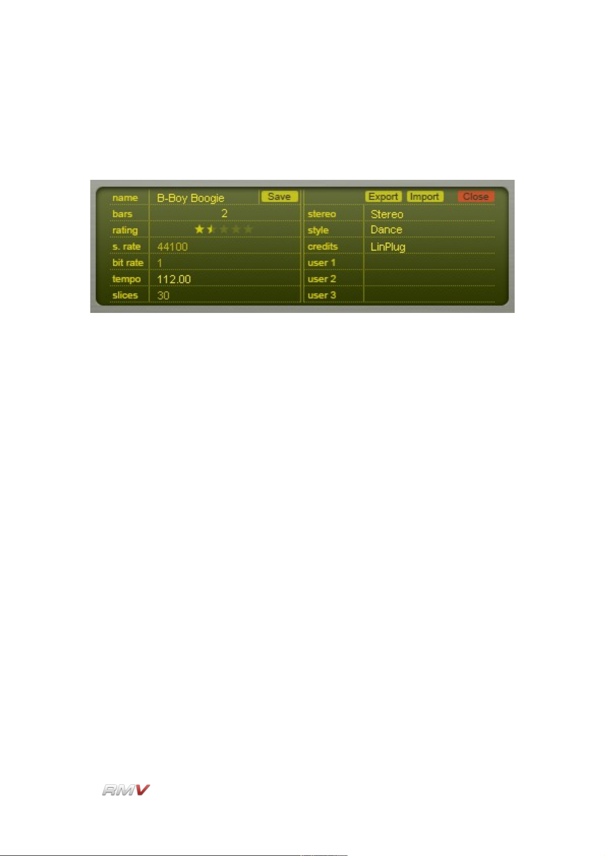
Loop Module
Loop Information Display
The Loop Information display shows the descriptive attributes of the currently loaded Loop.
It also enables a Loop's descriptive attributes to be set by the user prior to the Loop being
saved.
The Loop Information display operates in two ways. Firstly, when a Loop is loaded from
either the internal library or from an external location, the Loop Information display shows
the Loop's descriptive attributes (the actual attributes are listed below). Secondly, the Loop
Information display enables a Loop's descriptive attributes to be set prior to the Loop being
saved. Note that only some of the descriptive attributes can be edited by the user.
The following descriptive attributes can be saved in a Loop file:
Name: Displays the name of the current Loop file. This control is also used
to enter the name of the Loop file when a new Loop file is created.
Bars: Displays the number of bars that the current Loop file is fitted to. The
Bars control has a range of one to sixteen bars.
Rating: A rating of the quality of the Loop indicated in “stars”. The Rating
control has a range of zero to five stars.
S.Rate: Displays the sample rate of the current Loop file.
Bit Rate: Displays the bit depth of the current Loop file.
Tempo: Displays the default tempo of the current Loop file. The default tempo
is the tempo of the file prior to it being sliced.
Slices: Displays the number of slices that the current Loop file contains.
Format: Displays the format of the current Loop file (Mono or Stereo).
LinPlug Reference Manual 5.0.1 78
Page 79

Loop Module
Style: Displays the style of the current Loop file.
Credits: A reference to the creator of the Loop file.
User 1: A user-definable Loop file attribute.
User 2: A user-definable Loop file attribute.
User 3: A user-definable Loop file attribute.
Save: Saves the current Loop file settings to the RMV's internal Loop
library.
Export: Exports the current Loop file.
Import: Imports a Loop file from an external location (that is, not from the
RMV's internal Loop library).
Close: Closes the Loop Librarian.
Loop Search Input Display
The Loop Librarian's Search Input section is used to set the criteria used when searching
the RMV's internal library for Loops.
Thirteen search keys are available. These are: Name, Bars, Rating, S.Rate, Bit Rate,
Tempo, Slices, Format, Style, Credits, User 1, User 2, and User 3. The search keys are
used in combination with mathematical operators to determine the parameters of the
search. The thirteen search keys can be divided into two types: text keys and numeric
keys. The mathematical operators used with each search key depend upon the type of the
search key. Text keys can be searched using the following operators: “=”, “*<” and “<*>”.
Numeric search keys can be searching using the following operators: “<”, “>”, “=”, “<=” and
LinPlug Reference Manual 5.0.1 79
Page 80

Loop Module
“>=”. These operators are described below. In addition to this, the Loop Search Input
section enables any or all of the selected criteria to be used in the search. The search is
performed using the Search button. The search criteria can be set to the display's default
values using the Reset button.
Text Operators
=: Equal to. The “Equal To” operator finds all items in the database that
are exactly the same as the search term.
*<: Begins with. The “Begins With” operator finds all items in the
database that begin with the search term.
<*>: Contains. The “Contains” operator finds all items in the database that
contain the search term.
Numeric Operators
<: Less Than. The “Less Than” operator finds all items in the database
that are less than the search term.
>: Greater Than. The “Greater Than” operator finds all items in the
database that are greater than the search term.
=: Equal To. The “Equal To” operator finds all items in the database that
are equal to than the search term.
<=: Less Than or Equal To. The “Less Than or Equal To” operator finds
all items in the database that are less than or equal to the search
term.
>=: Greater Than or Equal To. The “Greater Than or Equal To” operator
finds all items in the database that are greater than or equal to the
search term.
Search Key
Name: The name, or portion of the name, of the Loop file to search for in the
internal library. The search results depend upon the operator used to
define the search (see above).
Bars: The number of bars in the Loop file. The Bars control has a range of
one to sixteen bars.
LinPlug Reference Manual 5.0.1 80
Page 81

Loop Module
Rating: The rating of the quality of the Loop file. The rating value can range
from zero “stars” to five “stars”.
S.Rate: The value of the sample rate of the Loop file.
Bit Rate: The value of the bit depth of the Loop file.
Tempo: The value of the default tempo of the Loop file. The default tempo is
the tempo of the file prior to it being sliced.
Slices: The number of slices that the Loop file contains.
Format: The format of the Loop file (either Stereo or Mono).
Style: The style of sound in the Loop file.
Credits: The reference to the creator of the Loop file.
User 1: The first user-definable Loop file attribute.
User 2: The second user-definable Loop file attribute.
User 3: The third user-definable Loop file attribute.
General
Reset: The Reset control restores the search parameters to their default
values.
Match: The match control enables the search to be defined so as to match
any or all of the selected criteria.
Search: The Search control starts the search of the internal Loop database.
LinPlug Reference Manual 5.0.1 81
Page 82

Loop Module
Loop Search Results Display
The Loop Librarian's Search Results display shows the results of a search of the RMV's
internal Loop database using the parameters supplied in the Loop Search Input section.
The Search Results section displays a list of all Loops that meet the search criteria. The
results are displayed as a list. The Search Results section has three controls. These are
Play, Preview and Load.
Preview: The Preview button is located to the right of the Loop file's name. The
Preview button is used to temporarily load and play the Loop.
Previewing the Pad includes all of the processing that is applied to
the Pad including filtering, effects processing and enveloping.
Load: The Load button loads the Loop file. Note that if the Loop Librarian is
closed without a new Loop being loaded the current Slicer is restored
to its initial state.
Sample Browser
The Sample Browser used to load Samples into the Loop module is similar to the Sample
Browser used in the Sampler module. Note that the Pads button is not present in the Loop
Module's Sample Browser as only one Pad is present in each Loop module. The Sample
LinPlug Reference Manual 5.0.1 82
Page 83
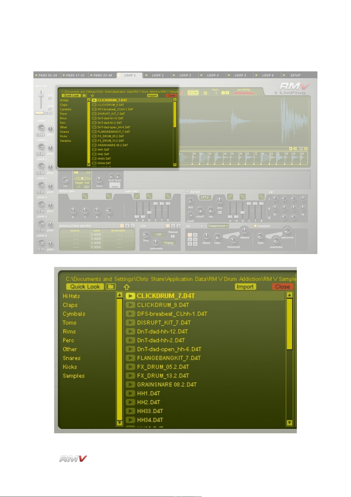
Loop Module
Browser is described in the Sampler Module section of this Guide.
LinPlug Reference Manual 5.0.1 83
Page 84
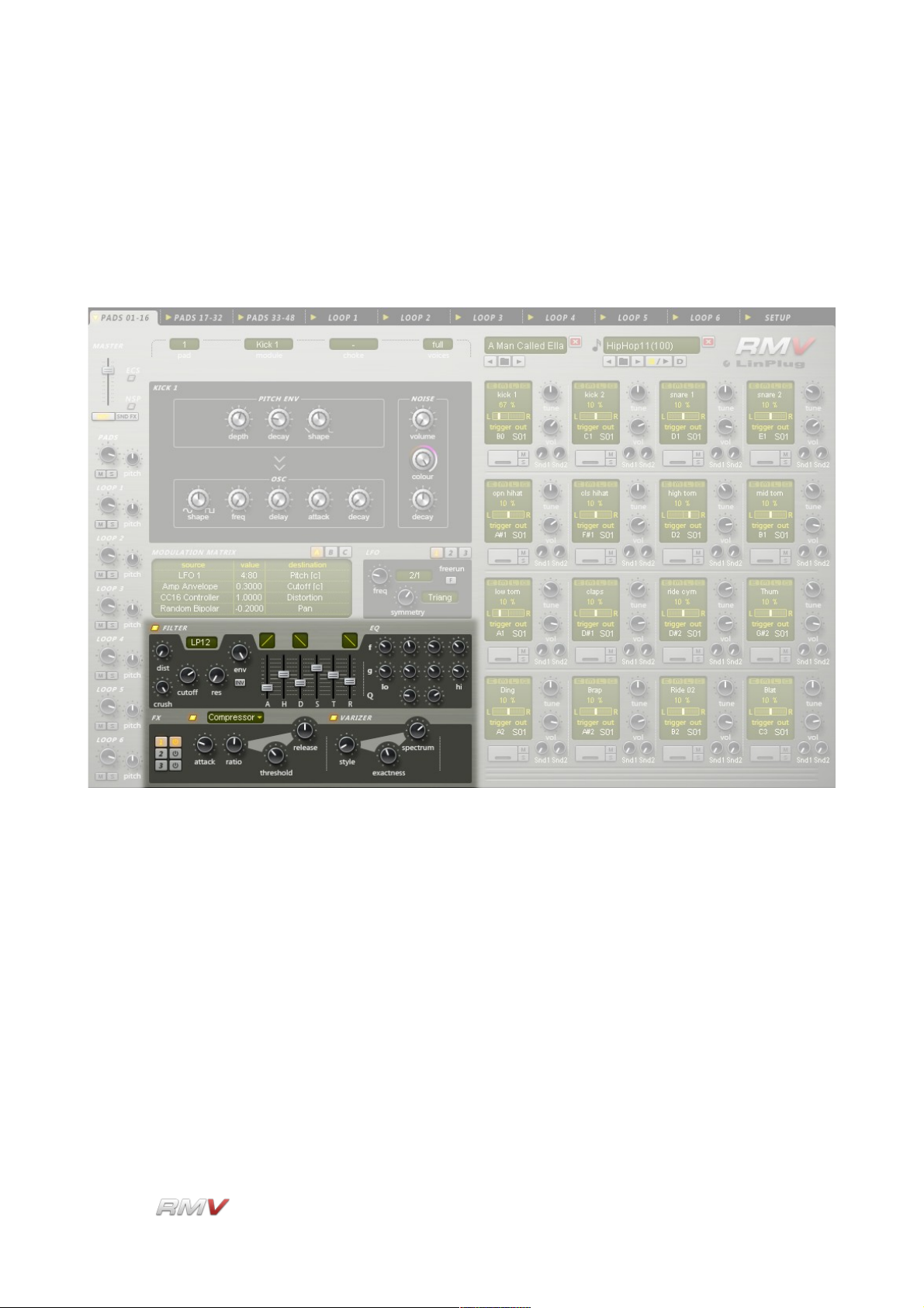
Signal Path
Signal Path
Once an Audio module is triggered, its signal can undergo further processing using the
RMV's Filter, EQ, Insert Effects and Varizer. Note that each Pad can also utilise the RMV's
Send Effects section which is described in the Send Effects section of this guide.
LinPlug Reference Manual 5.0.1 84
Page 85
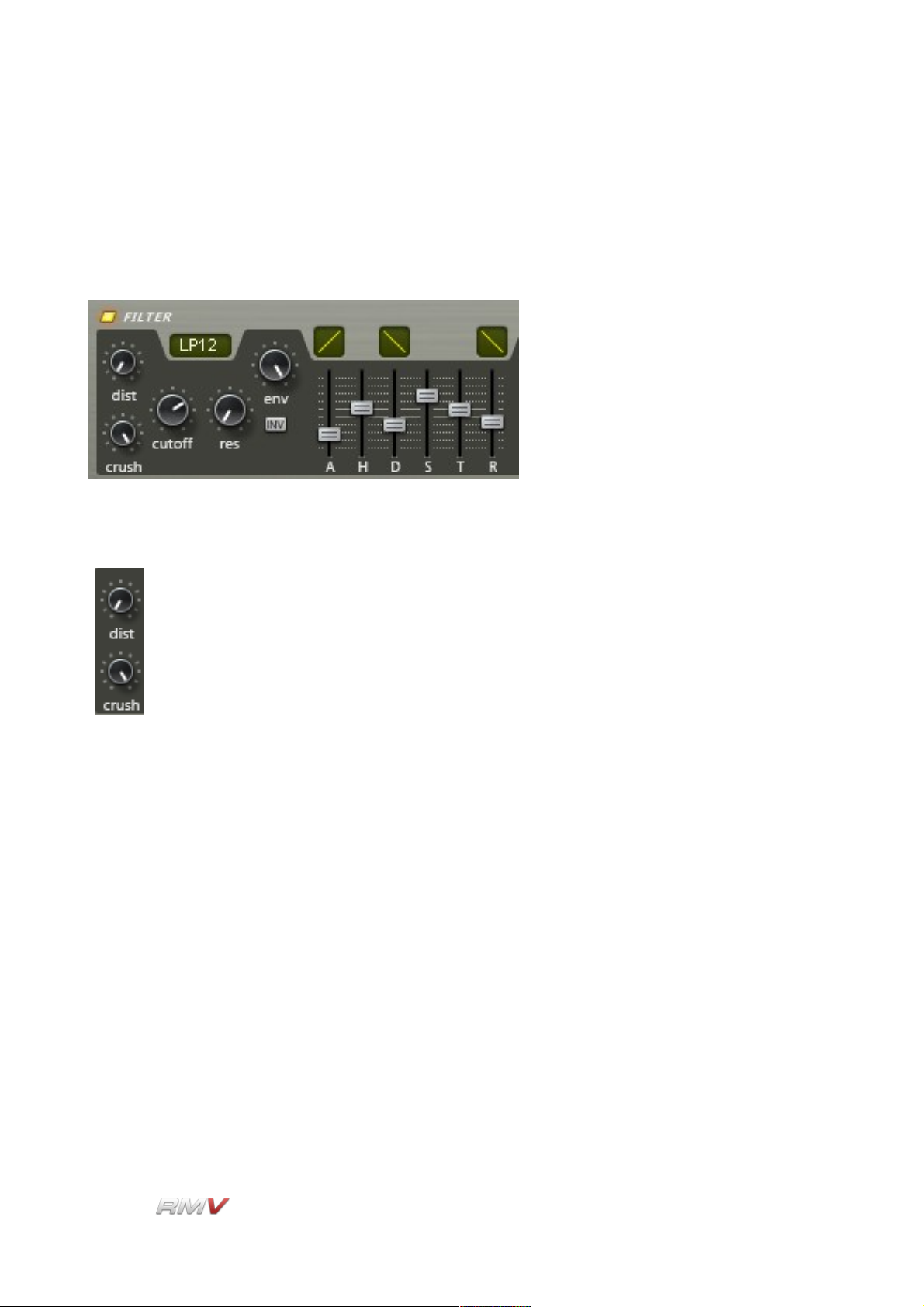
Signal Path
Filter
The RMV's Filter section is located between the Modulation Matrix and Effects sections.
The Filter section contains three subsections: The Distortion subsection, the Filter
subsection and the Filter Envelope subsection. These are shown below.
Distortion
The RMV's Distortion section contains two independent distortion units: Dist
(Distortion) and Crush (BitCrusher). These are located at the left of the RMV's
Filter section. The two effects units operate as "insert" effects (as opposed to
"send" effects) which means that they can be set independently for each Pad.
The Crush (BitCrusher) effect is located before the Dist (Distortion) effect in the signal
chain. The Crush effect enables the bit depth of the signal to be decreased, thereby
decreasing the resolution and making the sound rougher and noisier. The Distortion effect
saturates the signal adding a digital "hardness" to the sound.
Each Distortion effect has a single control which is described below.
Dist(ortion): The Distortion control enables the Drum Pad's output signal to be
distorted within a range of 0% (no distortion) to 100% (full distortion).
Crush: The BitCrusher control enables the bit depth of the output signal to
be reduced from oo bits (the signal is not changed) to 1.00 bits.
Reducing the bit depth adds a harsh, noisy quality to the sound.
Filter
The RMV's multi-mode filter is located to right of the Distortion subsection. The filter is
switched on or off using the button above the Filter section.
LinPlug Reference Manual 5.0.1 85
Page 86
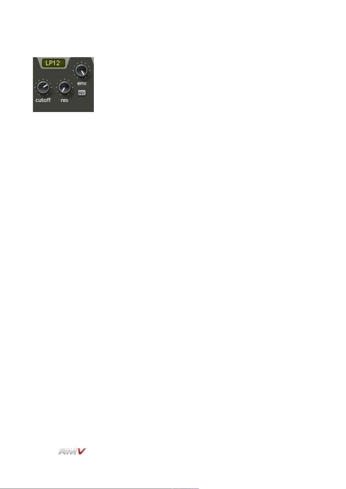
Signal Path
Eight different types of filter are available:
• LP12 ("Low Pass 12 dB/Octave")
• LP24 ("Low Pass 24 dB/Octave")
• HP12 ("High Pass 12 dB/Octave")
• HP24 ("High Pass 24 dB/Octave")
• BP12 ("Band Pass 12 dB/Octave")
• BP24 ("Band Pass 24 dB/Octave")
• BR12 ("Band Reject 12 dB/Octave")
• BR24 ("Band Reject 24 dB/Octave")
To change the filter type, click on the Type control and select the desired filter type.
The RMV Filter subsection contains controls for three parameters: Cutoff, Res(onance)
and Env(elope Depth), as well as an AHDSTR envelope for controlling the filter cutoff
frequency. There is also a button for inverting the filter envelope. These controls are
described below:
Cutoff: Cutoff is used to set the frequency (in Hz) of the filter cutoff point.
This has different effects depending on the type of filter being used.
For more information see the Glossary.
Res(onance): Resonance is used to set the amount of emphasis around the cutoff
frequency. Higher settings create a more pronounced peak in the
signal while lower settings produce a flatter response.
Env(elope Depth): Envelope Depth is used to set the degree to which the filter's
envelope effects the signal. Setting Env.Dth to 0.00 means that the
envelope has no effect on the filter. Setting Envelope Depth to 1.00
means that the filter is modulated by the envelope's full range.
Inv(ert): The Invert button is used to set either a positive or negative envelope
shape. This can be used for a range of effects including opening the
filter when a note is released (this is impossible with a non-inverted
envelope).
LinPlug Reference Manual 5.0.1 86
Page 87

Signal Path
Filter Envelope
The Filter Env(elope) section is located to the right of the Filter section.
It consists of 9 controls for setting the filter envelope parameters. These are described
below:
A(ttack): The Attack slider determines the length of time it takes for the filter
cutoff frequency to move from its initial value to the full envelope
depth. For example, if the Attack slider is set to 0.100 seconds, the
cutoff frequency will move from its initial value to full envelope depth
within 100 milliseconds.
Attack Envelope Shape: The Attack dial has a corresponding “curve” control located
above it that is used to set the shape of the envelope segment. The
shape of the segment can range from extreme negative exponential
to extreme positive exponential. To adjust the “curve” setting, click on
the control and drag the cursor up or down. The change in the
curve's shape will be shown on the control.
H(old): The Hold slider determines the length of time the filter cutoff
frequency is held at the maximum envelope depth.
D(ecay): The Decay slider determines the length of time that the filter cutoff
frequency takes to move from the full envelope depth to the Sustain
frequency after the Hold time has elapsed.
Decay Envelope Shape: The Decay dial has a corresponding “curve” control located
above it that is used to set the shape of the envelope segment. The
shape of the segment can range from extreme negative exponential
to extreme positive exponential. To adjust the “curve” setting, click on
the control and drag the cursor up or down. The change in the
curve's shape will be shown on the control.
S(ustain): The Sustain slider determines the frequency that the filter cutoff is
held at during the Sustain portion of the envelope. It should be noted
LinPlug Reference Manual 5.0.1 87
Page 88

Signal Path
that the length of the sustain phase cannot be displayed exactly as it
depends on when the instrument receives a Note-Off message. It is
shown in the display merely as an example.
T: The T slider sets the envelope's Sustain Time. When set to its
maximum value the sustain time is infinite, that is, it is controlled by
the MIDI Note Off command that trigger the Pad. It is also possible to
set a sustain time after that is independent of the MIDI Note off that
triggered the Pad.
R(elease): The Release slider determines the length of time that the filter cutoff
frequency takes to move from the Sustain frequency to 0 envelope
depth after a Note-Off message has been received.
Release Envelope Shape: The Release dial has a corresponding “curve” control located
above it that is used to set the shape of the envelope segment. The
shape of the segment can range from extreme negative exponential
to extreme positive exponential. To adjust the “curve” setting, click on
the control and drag the cursor up or down. The change in the
curve's shape will be shown on the control.
Don't forget that the filter's AHDSTR envelope is shown using a blue line in the Sampler
Display when the display is in "Waveform" mode and the Filter is switched On.
LinPlug Reference Manual 5.0.1 88
Page 89
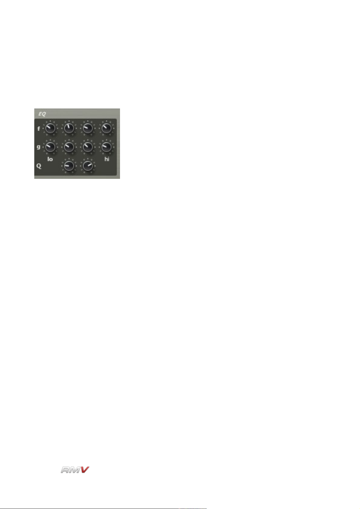
Signal Path
EQ
The RMV's EQ (Equalizer) section is located to the right of the Filter Envelope section. It
consists of 4 independent parametric equalizers.
The EQs are designed to work over different frequency ranges. The Lo EQ is located on
the left of the EQ section, while the Hi EQ is located on the right of the EQ section. In
between the Lo and Hi EQs are two variable-Q Mid EQs. Note that the two Mid EQ stages
are arranged in series.
The features of the three different EQ types are described below:
Lo Frequency: The Lo Frequency control is used to set the frequency at which the
EQ operates. A range of 20 Hz to 1000 Hz is available.
Lo Gain: The Lo Gain control is used to set the amount of gain that is applied
to the selected frequency. Note that the gain can be positive or
negative. A positive gain corresponds to boosting the signal while a
negative gain corresponds to cutting the signal. A range of -oo dB to
+18 dB is available.
Mid Frequency: The Mid Frequency control is used to set the frequency at which the
EQ operates. A range of 20 Hz to 11000 Hz is available.
Mid Gain: The Mid Gain control is used to set the amount of gain that is applied
to the selected frequency. Note that the gain can be positive or
negative. A positive gain corresponds to boosting the signal while a
negative gain corresponds to cutting the signal. A range of -oo dB to
+18 dB is available.
Mid Q: The Q (Quality) control sets the bandwidth of the EQs boost/cut. A
large value means that a wider bandwidth is affected by the filter. A
range of 0.33 to 12 is available.
LinPlug Reference Manual 5.0.1 89
Page 90

Signal Path
Hi Frequency: The Hi Frequency control is used to set the frequency at which the
EQ operates. A range of 440 Hz to 11000 Hz is available.
Hi Gain: The Hi Gain control is used to set the amount of gain that is applied
to the selected frequency. Note that the gain can be positive or
negative. A positive gain corresponds to boosting the signal while a
negative gain corresponds to cutting the signal. A range of -oo dB to
+18 dB is available.
LinPlug Reference Manual 5.0.1 90
Page 91

Signal Path
Insert Effects
The RMV's Insert Effects section is located on the lower left of the instrument's Pad Panel,
and on the lower right of the instrument's Loop Panel. Three independent stereo Effects
Racks are available for each Pad: Effects Rack 1, Effects Rack 2 and Effects Rack 3. All
three Effects Racks are identical.
Each of the RMV's three Effects Racks can be set to one of nine Effects Units. These are:
Delay, Ping Pong, Flanger, Filter, Reverb, Gator, WahWah, Compressor and Crusher. To
select an Effects Rack, use the Selection buttons labelled “1”, “2” and “3” at the left of the
Insert Effects section. To set the Effects Unit for a particular Effects Rack, click on the
Effect Name located above the Insert Effects section. This opens a popup menu displaying
the available Effects Units. Select one of the Effects Units in the popup menu to place it in
the Effects Rack.
All effects modules can be set to either "On" or "Thru" using the Power button to the left of
the Effect Type menu, or by using the three Power buttons to the right of the Selection
buttons. Note that only one Insert Effects Unit is displayed at a time. To switch between the
three Effects Racks, click on the Selection buttons labelled “1”, “2”, and “3” at the left of the
Insert Effects section.
Each Effect Unit's controls differ. All Effects Units are described in detail below.
LinPlug Reference Manual 5.0.1 91
Page 92

Signal Path
Delay
The Delay effect can be used to create "echoes" and other related effects. It features
controls for Wet, Time, Fract, Filter and Feedback.
Wet: The Wet control is used to set the balance between the processed
"wet" signal and the original unprocessed "dry" signal.
Time: The Time control is used for setting the delay time (in milliseconds).
This can range from 1 ms to 680 ms.
Fract: The Fract popup menu is used to synchronise the delay time with the
current tempo (see Appendix B for the range of possible sync
settings).
Filter: The Delay effect incorporates a variable low pass/high pass 6dB/Oct
filter which is adjusted using the Filter control. Turning the control to
the left introduces low pass filtering while turning the control to the
right introduces high pass filtering.
Feedback: The Feedback control is used to set the number of times the signal
repeats or "echoes". Turning the control to the right increases the
number of echoes that are added to the input signal.
LinPlug Reference Manual 5.0.1 92
Page 93

Signal Path
PingPong
The PingPong (Delay) effect can be used to create "echoes" that bounce around three
different positions in the stereo field. The PingPong (Delay) features controls for: Wet,
Stereo, Balance, Feedback, Left (Sync Time), Centre (Sync Time) and Right (Sync Time).
The PingPong (Delay) functions as follows: the input signal is first delayed by Centre
(Sync Time) amount, then it’s delayed by Left (Sync Time) amount and finally by the Right
(Sync Time) amount. If Feedback is applied, the Right (Sync Time) signal is fed back into
the left delay line, so that an alternating left-right delay is produced.
Wet: The Wet control is used to set the balance between the processed
"wet" signal (that is, the delayed signals) and the original
unprocessed "dry" signal.
Stereo: The Stereo control is used to set the panning positions of the left and
right delays in the stereo field. Turning the Stereo control to its
maximum value (in either a clockwise or anticlockwise direction)
gives the maximum panning value for the left and right delays.
Setting the Stereo control to the “12-O-Clock” position places the left
and right delays in the centre of the stereo field. Note that the Stereo
control can be used to exchange the pan positions of the left and
right delays. For example, if rotating the control in an anticlockwise
direction from the midpoint causes the processed signal to appear on
the right side of the stereo field first, then rotating the control in a
clockwise direction from the midpoint causes the processed signal to
appear on the left side of the stereo field first.
Balance: The Balance control is used to set the balance between the centre
delay and the left and right delays.
Feedback: The Feedback control is used to set the number of times the
processed signal repeats or "echoes".
Left (Sync Time): The left channel of the PingPong (Delay) can be independently
synced to the song's current tempo using the Left (Sync Time) popup
LinPlug Reference Manual 5.0.1 93
Page 94

Signal Path
menu (see Appendix B for the range of possible sync settings).
Centre (Sync Time): The centre channel of the PingPong (Delay) can be independently
synced to the song's current tempo using the Centre (Sync Time)
popup menu (see Appendix B for the range of possible sync
settings).
Right (Sync Time): The right channel of the PingPong (Delay) can be independently
synced to the song's current tempo using the Right (Sync Time)
popup menu (see Appendix B for the range of possible sync
settings).
LinPlug Reference Manual 5.0.1 94
Page 95
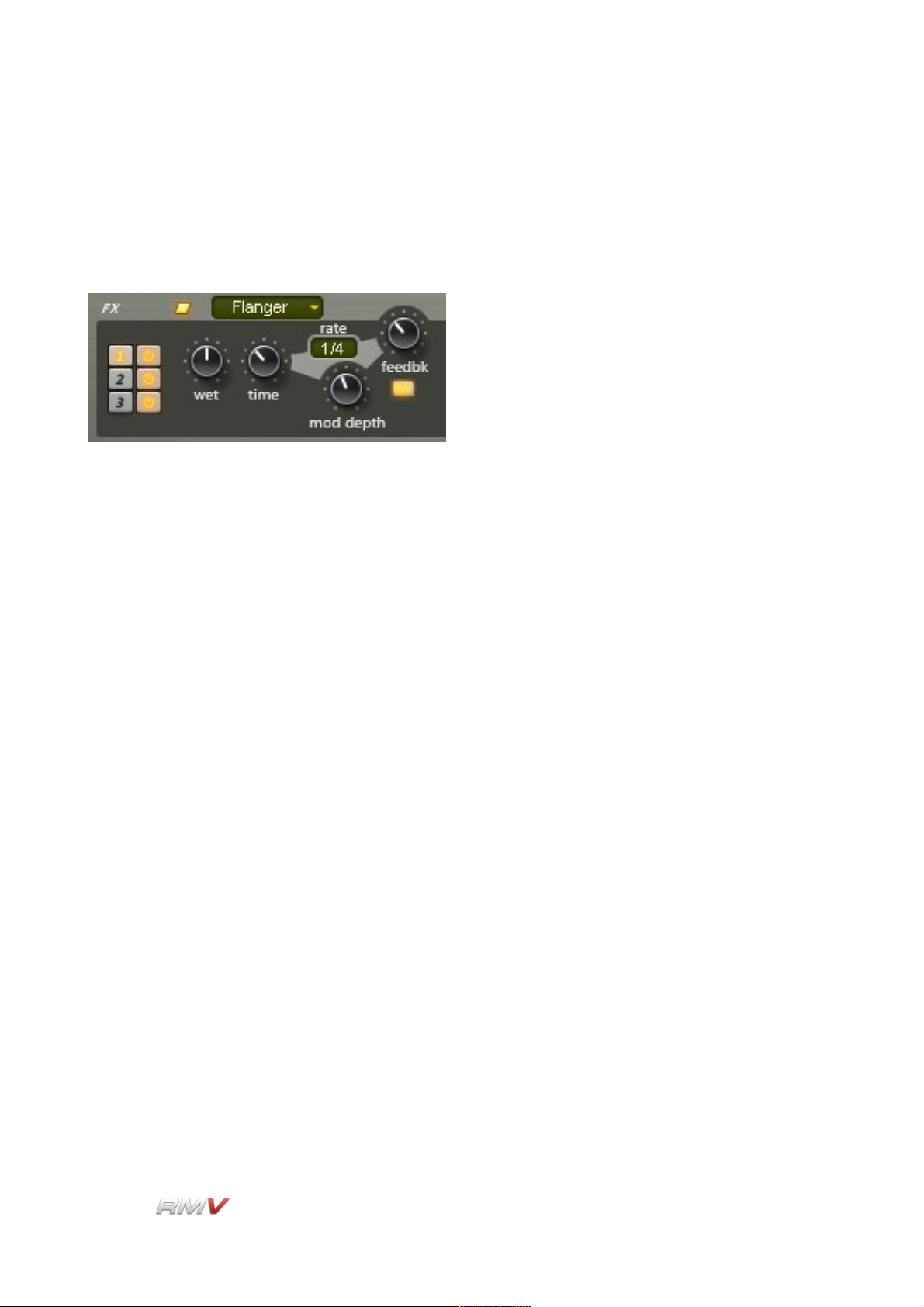
Signal Path
Flanger
The Flanger effect can be used to create the classic flanging sound produced by using two
analog tape machines playing back the same signal but with small (and changing)
differences in the playback speed of the machines.
The RMV's Flanger features controls for Wet, Time, Rate, Mod (Modulation) Depth,
Feedback and Invert.
Wet: The Wet control is used to set the balance between the processed
"wet" signal (that is, the “flanged” signal) and the original
unprocessed "dry" signal.
Time: The Time control is used to set the time of the flanger's delay, which
represents the delay time between the original (tape machine 1)
signal and the delayed (tape machine 2) signal.
Rate: The (Modulation) Rate control sets the speed of the flange effect
(that is, the speed of the cyclic changes of the two tape machines).
The rate is set as a fraction of the song tempo using the “Sync”
popup menu (see Appendix B for the range of possible sync
settings).
Mod Depth: The Mod (Modulation) Depth control is used to set the depth of the
flanging effect. The higher the setting, the more pronounced the
effect.
Feedback: The Feedback control is used to feed the processed signal back into
the input of the effect producing a richer, more pronounced flanging
effect.
Invert: The Invert control inverts the processed signal's phase against the
original signal, producing a subtly different flanging sound.
LinPlug Reference Manual 5.0.1 95
Page 96
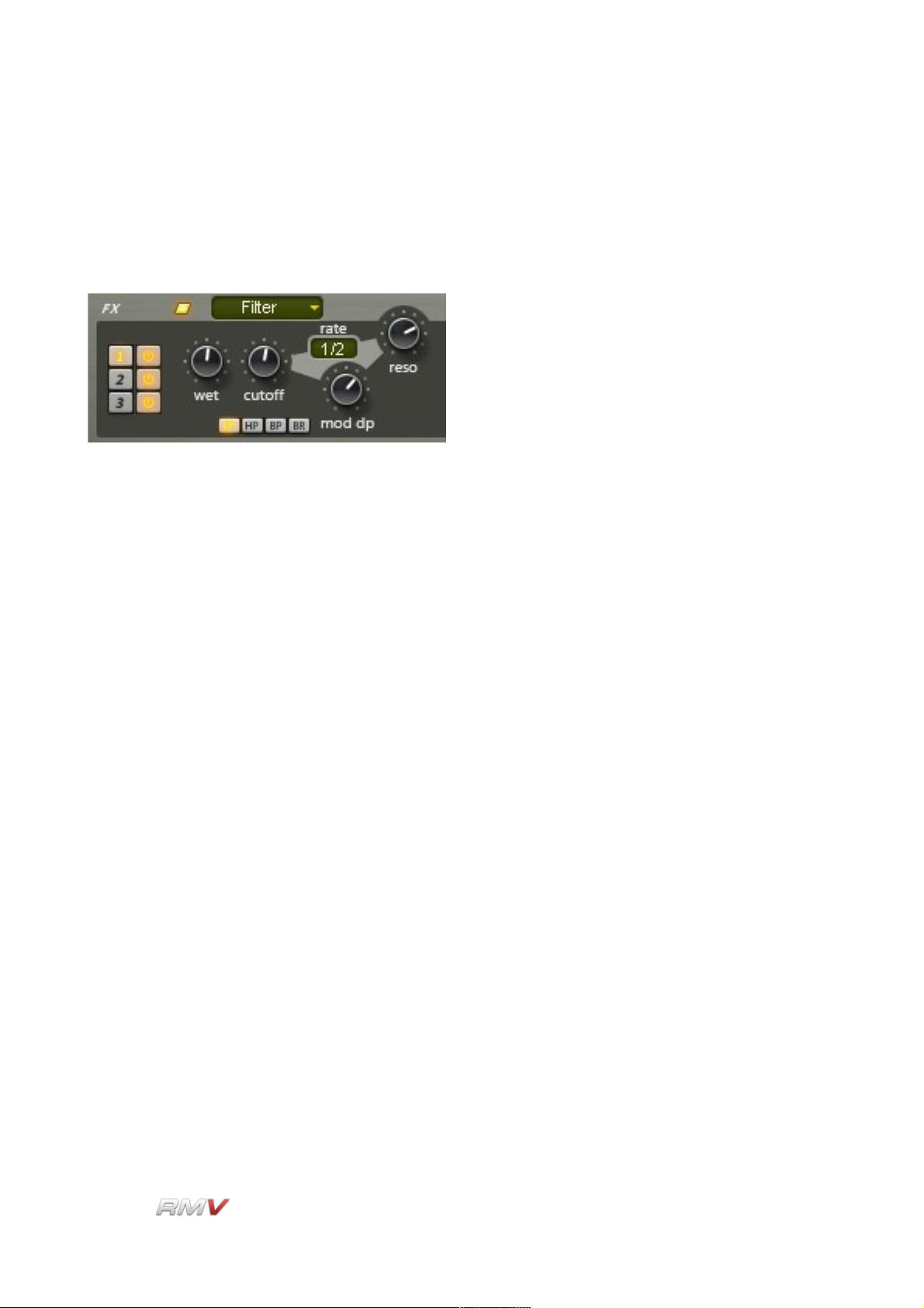
Signal Path
Filter
The RMV's Filter enables the frequency spectrum of the instrument's signal to be
controlled, allowing some frequency regions to pass through the instrument unaffected,
while other regions are either boosted or attenuated.
The RMV's Filter has six controls:
Type: The RMV's Filter can be set to one of four 12 dB filter types: LP (Low
Pass 12 dB), HP (High Pass 12 dB), BP (Band Pass 12 dB) and BR
(Band Reject 12 dB).
Wet: The Wet control is used to set the balance between the processed
"wet" signal (that is, the “filtered” signal) and the original unprocessed
"dry" signal.
Cutoff: The Cutoff control is used to set the frequency (in Hz) above which
frequencies are filtered out of the signal. Higher settings produce
brighter sounds while lower settings result in darker sounds.
Rate: The Modulation Rate of the Filter's Cutoff Frequency can be synced
to the song's current tempo using the Rate popup menu (see
Appendix B for the range of possible sync settings).
Mod DP: The Mod DP (Cutoff Frequency Modulation Depth) control is used to
set the depth to which the filter's cutoff frequency is modulated. A
setting of 0% means no modulation occurs, while a setting of 100%
means that maximum modulation occurs.
Reso: The Resonance control is used to set the amount of emphasis
around the cutoff frequency. Higher settings create a more
pronounced peak in the processed signal while lower settings
produce a flatter response.
LinPlug Reference Manual 5.0.1 96
Page 97
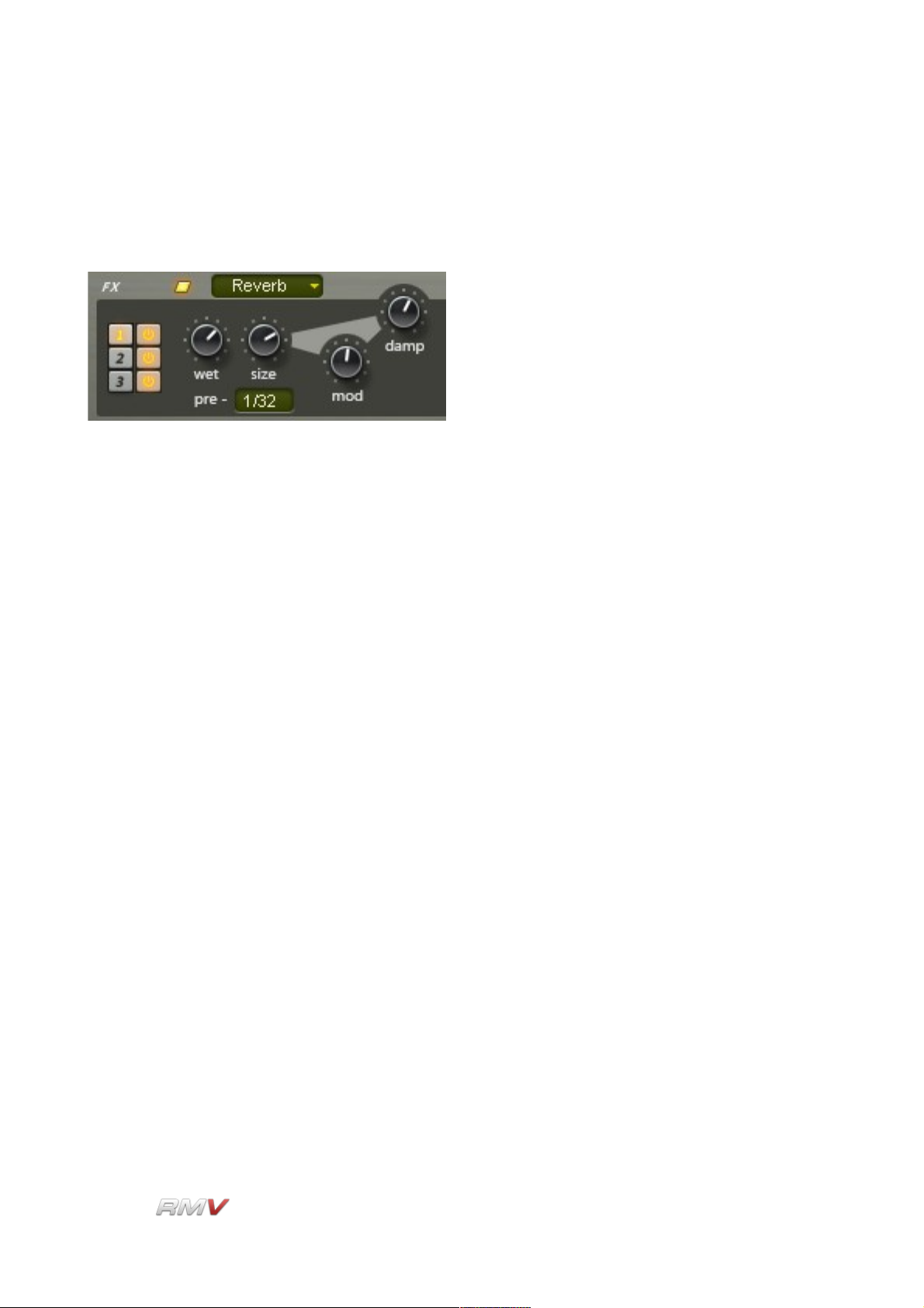
Signal Path
Reverb
The Reverb effect is used to add ambience to sounds, making them appear to be located
in an acoustic space.
The Reverb effect features controls for:
Wet: The Wet control is used to set the balance between the processed
"wet" signal (that is, the “reverberated” signal) and the original
unprocessed "dry" signal.
Size: The Size control is used to set the size of the simulated room. The
Roomsize varies from a small chamber up to a huge hall.
Pre: The Pre (Predelay) control is used to delay the processed signal by a
given amount (in milliseconds) so as to achieve a more natural
reverberation effect. Normally, shorter predelay times are applied in
the case of smaller room sizes while longer predelay times are
applied in the case of larger room sizes. The Pre (Predelay) popup
menu can be used to sync the predelay time with the current tempo
(see Appendix B for the range of possible sync settings).
Mod: The Mod (Modulation) control is used to set the rate at which the
Reverb's room size is modulated. The modulation effect is quite
subtle. Modulation can be turned off by turning the Mod
(“Modulation”) control fully anticlockwise.
Damp: The simulated room's wall materials can be adjusted with the Damp
(Damping) control. This parameter ranges from practically loss-free
reflecting walls (0% damping) up to very absorbent walls (90%
damping). In practical terms, the amount of damping determines the
amount of higher frequencies that are contained in the processed
signal: The higher the Damp (Damping) setting, the more that higher
frequencies are removed from the processed signal.
LinPlug Reference Manual 5.0.1 97
Page 98
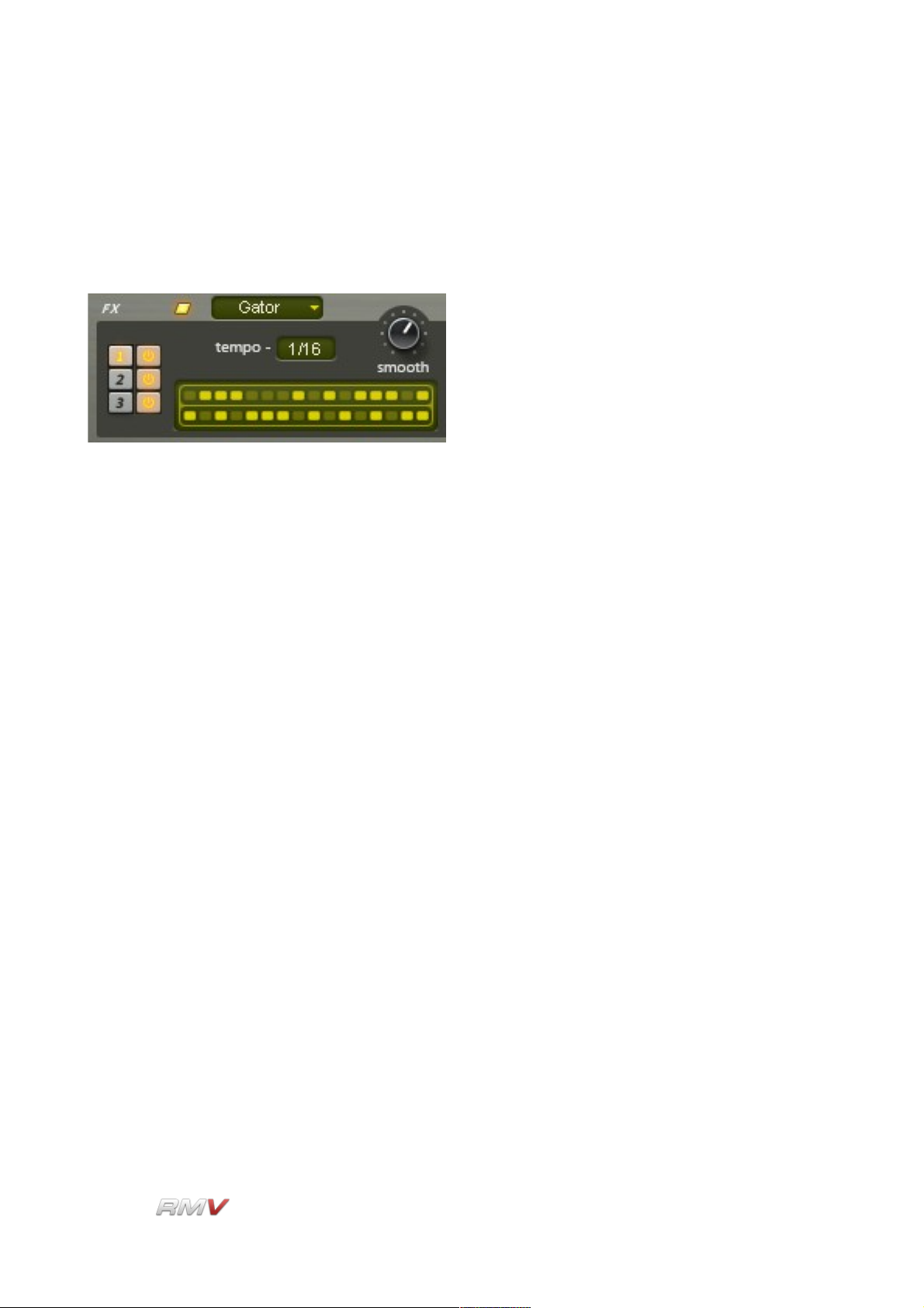
Signal Path
Gator
The Gator effect is a step-controlled audio gate that can be used to create rhythmic,
stuttering and pulsing effects. The effect is unique in that it separates the input signal into
left and right components, each of which can be gated independently.
The Gator effect contains three controls:
Smooth: The Smooth control sets the envelope shape of the gate for each
step value. A lower setting of the Smooth control creates a sharper
envelope shape that produces a more pronounced gating effect.
Increasing the value of the control “smooths” the envelope creating a
more pulsing, tremolo-like sound.
Steps: The Steps control consists of two rows of sixteen “buttons”, one for
each rhythmic step of the pattern. When a button is on, the signal is
passed through the effect. Alternately, when a button is off, the signal
is gated. The duration of each step depends on the setting used in
the Tempo control (described below).
Tempo: The Tempo control sets the duration of each step. For example, a
setting of 1/16 means that each pattern step is equivalent to a 16th
note. Note that the overall tempo at which the Gator effect operates
is set in the host software.
LinPlug Reference Manual 5.0.1 98
Page 99
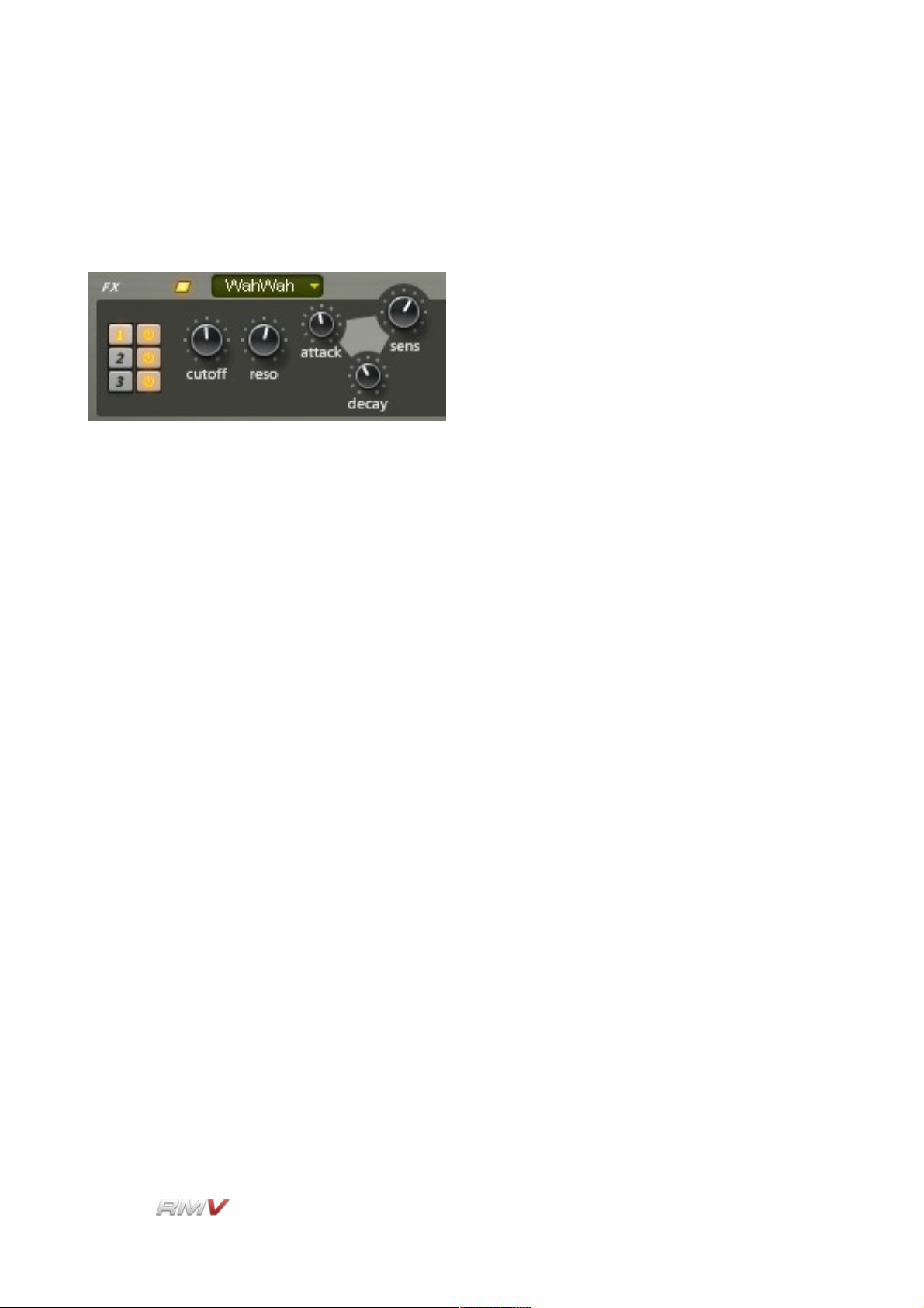
Signal Path
WahWah
The WahWah effect is an amplitude-controlled bandpass filter that can be used to produce
vocal-like sounds, particularly “wah-type” sounds.
The WahWah effect contains five controls:
Cutoff: The Cutoff control is used to set the centre frequency (in Hz) at which
the bandpass filter operates.
Reso: The Reso (Resonance) control is used to set the amount of
emphasis around the cutoff frequency. Higher settings create a more
pronounced peak in the signal while lower settings produce a flatter
response.
Attack: The Attack control is used to set the response time of the filter to
changes in the input signal's amplitude. Faster Attack times mean
that the wah effect is triggered more quickly, while slower Attack
times introduce a delay before the wah effect is produced.
Decay: The Decay control is used to set the recovery time of the filter after
the input signal's amplitude has changed. Faster Decay times mean
that the wah effect returns to its default value more quickly, while
slower Decay times mean that the wah effect returns to its default
value more slowly.
Sens: The Sensitivity control sets the degree to which the input signal's
amplitude affects the filter cutoff frequency. Lower values produce a
less-pronounced wah effect, while higher values produce stronger,
more vocal-like wah sounds.
LinPlug Reference Manual 5.0.1 99
Page 100
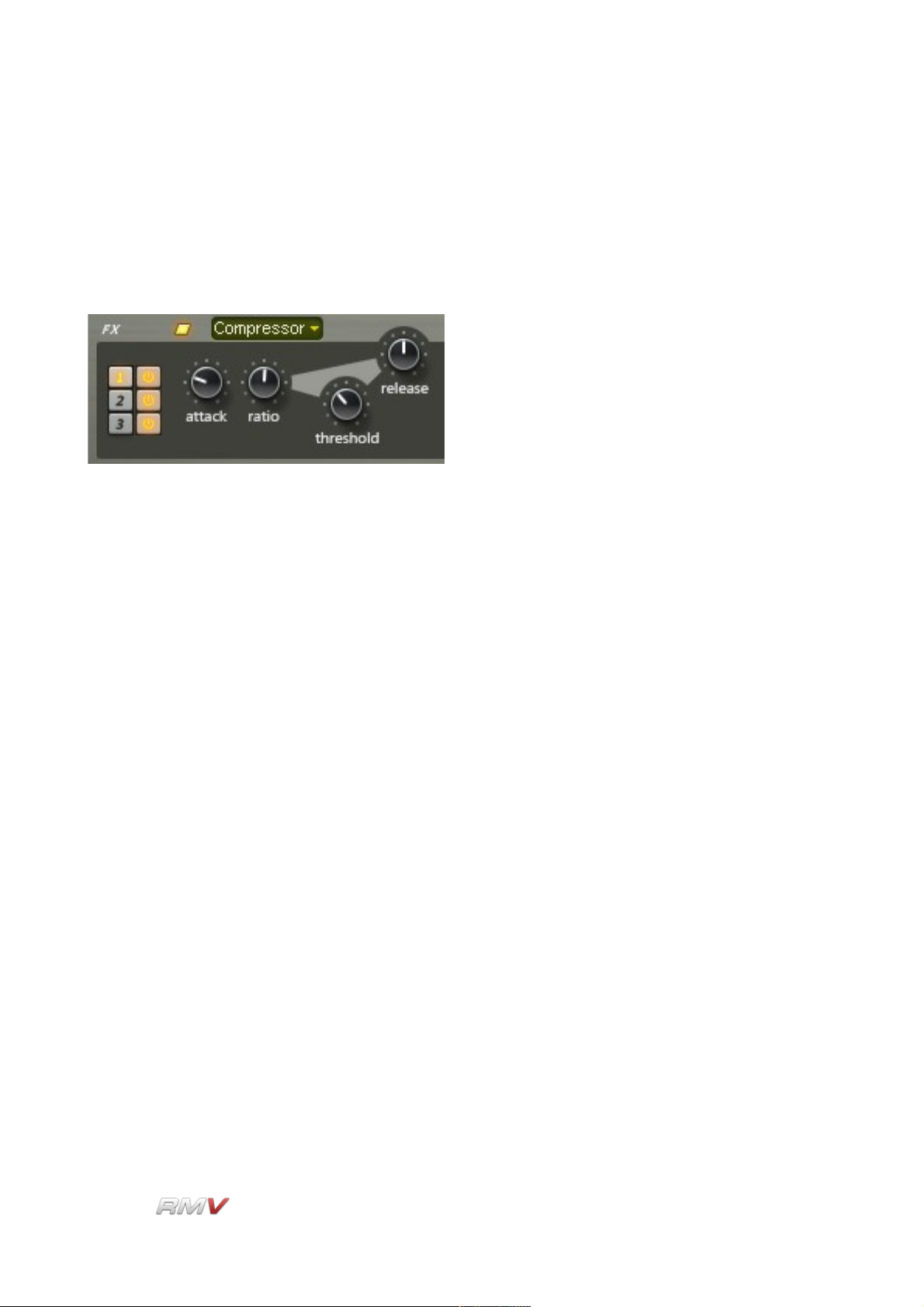
Signal Path
Compressor
The RMV's Compressor can be used to control the dynamic range of the effect's input
signal. Compression can be used to increase the perceived volume of a sound by reducing
the level transient peaks, and thus allowing for an increasing of the average signal level
without clipping.
The RMV's has four controls: Attack, Ratio, Threshold and Release. The Compressor's
controls are described below. Because compression reduces the average amplitude of the
input signal it is often necessary to increase the signal's amplitude once it has been
compressed. The RMV's provides this “make-up” gain automatically.
Attack: The Attack control is used to set the speed at which the compressor
responds to changes in the input signal.
Ratio: The Ratio control is used to set the ratio between the input and
output level of signals that are above the Compressor's Threshold
level. The compression ratio can be set anywhere between 1:1 and
10:1.
Threshold: The Threshold control is used to set the signal level at which the
Compressor begins operating. The Threshold dial has a range of -24
to 0dB and automatically adjusts the make-up Gain to give 0dB
signal peaks.
Release: The Release dial sets the amount of time that it takes for the
compressor to return to unity gain after the signal falls below the
Threshold level. The Release time has a range of 0.001 to 4.000
seconds.
LinPlug Reference Manual 5.0.1 100
 Loading...