

Page 1

MANUAL
Page 2

Copyright LinPlug Virtual Instruments GmbH, 2005.
All rights reserved.
All technical specifications of the products specified in this manual may be subject to change
without notice. The documents may not be changed, especially copyright notices may not be
removed or changed. LinPlug and all LinPlug product names are trademarks of LinPlug
Virtual Instruments GmbH. Mac and the Mac logo are trademarks of Apple Computer, Inc.,
registered in the U.S. and other countries. The Build for Mac OS X graphic is a trademark of
Apple Computer, Inc., used under license. The Audio Units logo and the Audio Units symbol
are trademarks of Apple Computer, Inc. Microsoft® and Windows® are trademarks of
Microsoft Corporation, registered in the U.S. and other countries. Cubase and VST are
registered trademarks of Steinberg Media Technologies GmbH. All other trademarks are the
property of their respective owners.
Page 3

Credits
Concept by Maxx Claster and Peter Linsener
Instrument by Maxx Claster and Pavol Markovič
Graphics by Branislav Pakić
Sounds by BIG!TONE, ProSounds, Summa, Tim Conrardy
Manual by Chris Share
Many thanks to Alex Hapted, the “mighty hero” Brice Duncan, Cliff Douse,
Dan Rose, (Abletons) Frank Hoffmann, the microtuned Jacky Ligon, Joakim
Fahlström, Kelvin Russell, “Superflausch” Marco Lehmann, Martin Pace,
“Biller” Michael Kjeldgaard, Ned Bouhalassa, Patrick Anglard, Patrick
Robert, “Tonal Axis” Richard Hider and ToTc-Frank!
Manual 1
Page 4

Welcome
Thank you for purchasing the Octopus Dual Matrix Synthesizer.
The Octopus is a fully professional, highly-flexible, easy-to-use software
synthesizer designed for creating music on your personal computer.
The Octopus's key features include:
Frequency Modulation synthesis with 10 modulation sources and 8
modulation destinations (full cross-modulation, adjustable feedback for
any oscillator)
8 additive oscillators using sample-based or user-created waveforms
Two independent classic multimode filters (filters are available as FM
sources)
Up to 32 envelopes with multiple, syncable segments, free-run, looping
and adjustable slope
Graphical envelope editor with sophisticated editing functions
Envelopes can be used to modulate a wide range of parameters
including amplitude, mix, panning, pitch, frequency and phase
Stereo effects section with 4 effects (parametric EQ, chorus, delay and
reverb)
Two step sequencers
A selection of high quality presets in a wide range of styles
This manual describes all aspects of the Octopus synthesizer and is
designed so that your use of this software is as efficient and as enjoyable
as possible.
We feel that the Octopus is an exceptional instrument because of its unique
sound and character. We hope you get a lot of pleasure using the Octopus
synthesizer and that it becomes an integral part of your music-making.
The LinPlug team, December 2005
2Manual
Page 5

Table of Contents
Credits............................................................................................................1
Welcome........................................................................................................2
Installation......................................................................................................5
Features.........................................................................................................6
Overview........................................................................................................7
Controls..........................................................................................................9
Oscillator Matrix...........................................................................................10
Sampler........................................................................................................12
Oscillator Editor............................................................................................15
Filter.............................................................................................................19
Envelope Editor............................................................................................21
Overview..................................................................................................21
Envelope Destination...............................................................................22
Envelope Editing......................................................................................23
Fix Points.................................................................................................25
“+-”...........................................................................................................25
Numerical Display....................................................................................25
KBD/VEL..................................................................................................25
MIDI Modulation.......................................................................................26
TMP Sync................................................................................................26
Release....................................................................................................27
Free-Run.................................................................................................27
KBD Rate Scaling / VEL Rate Scaling.....................................................28
Envelope Matrix...........................................................................................29
Envelope Bank Select/Envelope Select..................................................30
Envelope Editor Menu.............................................................................30
Matrix Nodes...........................................................................................31
Effects..........................................................................................................32
Chorus.....................................................................................................32
Delay........................................................................................................33
Reverb.....................................................................................................35
Equalizer..................................................................................................36
Manual 3
Page 6

Master..........................................................................................................37
Step Sequencer...........................................................................................38
Seq 1/Seq 2.............................................................................................38
Menu........................................................................................................39
Steps........................................................................................................39
Shuffle.....................................................................................................40
Transpose................................................................................................40
Random...................................................................................................40
Ping-Pong................................................................................................40
Pattern Display........................................................................................41
Unison/Glide................................................................................................42
Transp (Transpose).................................................................................42
Voices......................................................................................................42
Unison......................................................................................................42
Detune.....................................................................................................43
Glide........................................................................................................43
Legato......................................................................................................43
Bend........................................................................................................43
Miscellaneous..............................................................................................44
Bank/Preset.............................................................................................44
File Controls............................................................................................45
Microtuning..............................................................................................45
LinPlug/Octopus Logos...........................................................................45
Registration..................................................................................................46
Optimizing CPU Usage................................................................................48
Glossary.......................................................................................................49
MIDI Implementation Chart..........................................................................51
Appendix A: Using TUN files in the Octopus...............................................52
Tutorial: Programming your own patches....................................................54
4Manual
Page 7

Installation
Installation on PC
The Octopus comes with its own Installer. On the Octopus CD you will find
a file named OctopusInstaller.exe. Double-click on this file to begin the
installation process. The Installer will guide you through the installation
process. Make sure you choose the right directory, so your host software
finds the Octopus instrument.
Refer to your host software's manual if you are unsure about where the host
software plug-in directory is located.
The instrument file Octopus.DLL and the Octopus manual and presets will
be placed in the chosen directory. The next time you start your host
software the Octopus will be listed in the host software's Instrument list.
Installation on Mac
The Octopus comes with its own Installer. On the Octopus CD you will find
a file named Octopus Installer.dmg. Double-click on this file to open the
image, then double-click the installer program to begin the installation
process.
You will be guided through the installation process. The instrument file
Octopus and the Octopus presets will now be placed in the appropriate
directory for virtual instruments on your Mac. The next time you start your
host software the Octopus will be listed in the host software's Instrument
list.
Common to Mac and PC
Once you've installed the Octopus you'll need to register it. The registration
process is described in the Registration section of this manual.
If you have any questions regarding the installation of Octopus please
contact our support team at www.linplug.com/support/support.htm
Manual 5
.
Page 8

Features
The Octopus contains a range of features designed to make your musicmaking more efficient and enjoyable. These features include:
2 independent sound generation modules
8 additive oscillators
Each oscillator can contain up to 32 harmonics
Each oscillator's spectrum is fully editable
Each oscillator has sample-analysis capability
Additive oscillators can be configured for 8-oscillator FM synthesis
Waveforms can be easily edited by the user and new waveforms can be
created in seconds
Matrix-FM with 8 oscillators, full cross-modulation, adjustable feedback
for any oscillator
8-slot sampler with adjustable keyboard range
Sampler loads WAV/AIFF samples up to 24bit/192kHz
2 independent, multimode filters with modulatable cutoff and resonance
Filters are available as FM sources
Up to 32 envelopes with up to 64 host-syncable segments, free-run,
loop and adjustable slope (curve)
Envelope matrix offers modulation of amplitude, mix, panning, pitch,
frequency, phase of any oscillator and filter cutoff and resonance
Graphical envelope editor with advanced editing capabilities
Envelopes can be scaled to keyboard and velocity independently
A stereo effects section containing 4 effects units including chorus,
delay, reverb and a 4-band parametric equalizer
Warm tube-like distortion
2 sophisticated 32-step sequencers/arpeggiators
Unison and Glide
Microtuning support
12-voice polyphony (CPU dependent)
Adjustable voice limit (1...12)
Sample accurate timing
Fully recognizes Velocity, Aftertouch, Pitch bend, Modwheel and various
other MIDI controllers
Envelopes, oscillator waves, sequences, and complete sound programs
can be saved to disk and loaded from disk
6Manual
Page 9

Overview
The Octopus is a 12-note polyphonic, 8-Oscillator hybrid FM
Matrix/Sampling synthesizer with some extraordinary features. The
instrument has a modular design that is divided into 7 modules. These are:
an 8-Oscillator FM Matrix module, a Sampler module, a Filter module
containing 2 multi-mode analog-style filters, an Envelope Editor module, an
Envelope Matrix module, an Effects module containing 4 independent
effects processors, and a dual Step Sequencer module.
With respect to signal generation, the Octopus consists of two independent
modules. Audio signals are created by either a sample or an additive
oscillator that gets pitch information from the synthesizer's MIDI input (either
externally from a hardware device or internally from software). It is
important to remember the MIDI information might be transformed by the
Step Sequencers if they are activated.
The output of each Sampler slot can be sent to either (or both) of the Filters
or the output Mix. The output of each Oscillator can be sent to any of the
the following destinations: an Oscillator (including itself), a Filter or the
output Mix. In addition, the output of each Filter can be sent to an Oscillator,
the other filter or the output Mix. When the output of an Oscillator is sent to
either itself or another Oscillator, the first Oscillator modulates the second
Oscillator in a process called Frequency Modulation (FM) synthesis. It is
important to realise that the result of FM synthesis is not an additive mixture
of the two signals. In fact, one signal modulates the other producing rich,
complex audio spectrums. Oscillator routing is set in the Oscillator matrix.
Following the Filter section is the Octopus' Effects section which contains 4
independent effects processors (chorus, stereo delay, reverb, and
parametric EQ). The effects are in series from left to right according to the
instrument's front panel. Each effects processor is described in detail later
in this manual. Note that the Octopus also contains a distortion effect which
is located in the Master section.
The audio outputs of the Octopus are automatically connected to the input
of your host software's mixer. Here you can set the overall pan position of
the Octopus' output.
Manual 7
Page 10

All modulation within the Octopus is performed using envelopes. Envelopes
are the key to modulating audio signals within the Octopus and can be used
to produce a wide range of modulation effects.
Available modulation destinations include: Amplitude, Mix, Panning, Pitch,
Frequency, Phase, Cutoff and Resonance. The Envelope Editor features
sophisticated editing capabilities that make working with it very fast and
easy. MIDI Controllers can also be used in combination with the Octopus’
envelopes.
The Envelope Matrix is used to set the actual destination of the envelope
(for example, the amplitude of Oscillator 1). Available destinations include
all 8 Oscillators, the 2 Filters and the Sampler.
Hopefully, this chapter has given you a brief overview of how the Octopus
works. More detailed information can be found in the following chapters.
8Manual
Page 11

Controls
Most Octopus controls are changed by clicking on the control and then
moving the mouse either upwards to increase the parameter’s value, or
downwards to decrease it.
Holding down the Alt key while moving the mouse gives finer control over
the parameter being changed.
Several controls (in particular the Oscillator Pitch control and the Envelope
Matrix controls) have different behaviour depending upon where they are
clicked. Clicking to the right of the “.” changes the value in decimal units,
while clicking to the left of the “.” changes the value in whole-number units.
Holding down the CTRL key on PC and Command (Apple) key on Mac
while clicking on a control sets the control to its default value (e.g. for Matrix
node controls it sets the control's value to 0.0).
The original Apple mouse does not have a right button, use CTRL-click
where right click is needed.
Manual 9
Page 12

Oscillator Matrix
The Octopus has two different modules for generating sound. These are
the Oscillator Matrix and the Sampler. These two modules are located in
the upper left corner of the instrument's front panel. Only one of these
modules is visible at any time. If the Oscillator Matrix is not visible (that is,
the Sampler is currently being displayed) then you can switch to the
Oscillator Matrix by clicking on the Matrix/Sampler buttons which are
located in the lower right corner of the Oscillator Matrix/Sampler module.
This section of the manual describes the Oscillator Matrix module. For
information about the Sampler module please refer to its section in this
manual.
The Oscillator Matrix is essentially a router which allows you to send audio
signals to various destinations within the synthesizer.
Sources
Signal sources are located on the left-hand side of the module and consist
of the instrument's 8 Oscillators and 2 Filters.
Each source can be sent to any or all of 11 different destinations. These
include the instrument's 8 Oscillators (for FM synthesis) and 2 Filters (for
filtering), or the main output mix. The panning of the Mix signals can also
set here.
Each Oscillator has its own On/Off switch. To activate an Oscillator, click on
the Oscillator's label. When an Oscillator is switched on it is illuminated,
otherwise it is dark. If you don’t want to use one of the Oscillators it's best to
switch it off as this conserves CPU resources. However, make sure that at
10 Manual
Page 13

least one Oscillator is switched on, otherwise the module will not produce
any output.
The parameters for each Oscillator can be set in the instrument's Oscillator
module. This module is described in the Oscillator section of this manual.
Destinations
The destination for each Oscillator is located from left-to-right across the
Matrix. Each Oscillator can be sent to Oscillators 1 to 8, the inputs of the 2
Filters and the output mix. The output from each Filter can also be routed
back to any or all of these destinations.
Nodes
The amount of signal sent to a particular destination is determined by the
setting of the Matrix node. This can range from -1.0 to +1.0. When the
signal level is set to 0.0 the node is deactivated.
One of the key features of the Octopus is that its Oscillator Matrix can be
used to produce FM (Frequency Modulation) synthesis. See the Quickstart
section of this manual for a simple example of how to create an FM patch.
Manual 11
Page 14

Sampler
The Octopus' Sampler module is located in the upper-left corner of the
instrument's Front Panel. If the Sampler module is not visible (that is, the
Oscillator Matrix is currently being displayed) it can be accessed by clicking
on the Matrix/Sampler button located in the lower-right corner of the
module. This section of the manual describes the Sampler module. For
information about the Oscillator Matrix module please refer to its section in
this manual.
The Octopus' Sampler module functions as an audio sampler playing back
audio files when triggered.
Sampler Slots
The Sampler module consists of 8 sample slots located on the left of the
module. Each slot can contain one audio sample. When a slot is empty it is
deactivated. This is indicated by its dark colour and the absence of a
sample name in the slot's display.
Clicking on the "sample slot" opens the Load Sample dialog which enables
samples to be loaded into the currently selected slot. Once a sample is
loaded into a slot, its name is displayed. To the right of the sample's name
is the Delete button ( Trash icon). Clicking on this button removes the
sample from the selected slot.
Each sample slot has the following controls: Low Key, Root Key, KBD TRK
(Keyboard Tracking), USE LPS, F1/F2, PAN and MIX. These controls are
described below.
12 Manual
Page 15

Low Key
The Low Key setting is used to determine the lowest note that triggers the
selected sample. Each sample is played from its Low Key up to anothers
sample's Low Key (no overlapping is permitted).
Root Key
The Root Key setting determines the key that plays back the sample at its
original pitch. The Root control enables you to set the unity note of the
loaded sample. If, for example, you set Root to C1 and play a C2 the
sample will be played one octave above its original frequency. If you wish to
obtain the most natural sound then you should set the sample's root note to
the same note as the one at which the sample was initially recorded.
Otherwise the sample will be pitch-shifted. In many cases however, it is
precisely these effects that give the sample an interesting and unusual
sound.
KBD TRK
The KBD TRK (Keyboard Tracking) button setting determines whether the
sample tracks the pitch of incoming MIDI messages. If Track is switched off
the frequency of the sample is fixed at its original value.
Use LPS
The USE LPS button setting determines whether or not the sample loops
when it is played back. If USE LPS is set to Off then the sample will only
play once each time it is triggered. If the sample contains loop points, these
are used for looping, otherwise the entire sample loops.
F1/F2
The F1 and F2 controls determine the amount of signal that is sent to Filter
1 or Filter 2 respectively.
Manual 13
Page 16

Pan
Each sample slot can have its own pan position. This is set using the slot's
PAN control.
Mix
Each sample slot can have its own mix level. This is set using the slot's MIX
control. The Mix setting determines the samples playback level.
Sampler Amp and Pan
In addition to the above-mentioned controls, there are also two global
controls for the Sampler module. These are the Sampler Amp (Amplitude)
and the Sample Pan (Panorama).
The Sampler Amp (Amplitude) control sets the overall output level for the
combined mix of all currently loaded samples.
The Sampler Pan (Panorama) control sets the overall panning position for
the combined mix of all currently loaded samples.
14 Manual
Page 17
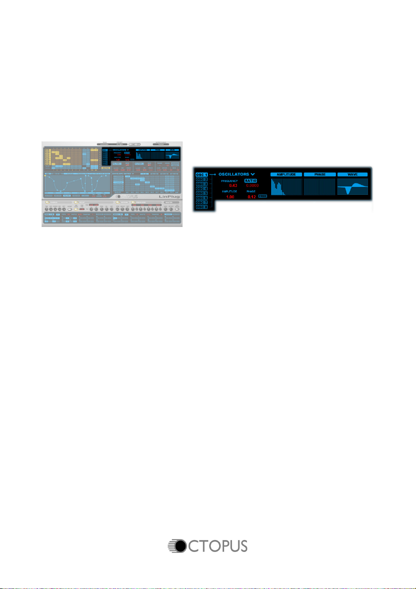
Oscillator Editor
The Octopus' Oscillator Editor module is located on the upper-right of the
Front Panel. This module contains the controls for editing each of the
instrument's additive oscillators.
Overview
Each of the Octopus' 8 Oscillators is made up of 32 harmonics. The
amplitude of each harmonic can be edited in the Harmonic Amplitude
Editor. The Oscillator Editor enables you to load and analyse waveforms
however it is important to remember that only the first 32 harmonics present
in the waveform will be used. As such, rich, noisy waveforms may not be
reproduced with 100% accuracy. At first, it may appear that 32 harmonics is
not enough to produce rich waveforms, however one of the key features of
FM synthesis is its ability to produce complex waveforms from simple
source signals. For example, most hardware FM synths only contain sine
wave oscillators.
The Oscillator Editor module contains the following controls: Oscillator
Select, Oscillator Menu, Harmonic Amplitude Editor, Harmonic Phase
Editor, Frequency, Pitch, Amplitude, Phase and Free. There is also a
waveform display that shows the shape of the current Oscillator's
waveform. These controls are described below.
To select on Oscillator, click on one of the Oscillator Select buttons at the
left of the module. The selected Oscillator is then highlighted and the
Oscillator Editor module now displays the settings of the selected Oscillator.
Manual 15
Page 18

Waveform Import / Export and Editing
Oscillator Waveforms can be created in two different ways: they can be
created in the waveform editors (amplitude and phase) or they can be
generated automatically from imported audio samples.
To create a user-defined waveform, first select an Oscillator. Each
Oscillator's waveform can consist of 32 harmonics. The amplitude of each
harmonic can be individually edited in the Harmonic Amplitude Editor by
clicking and dragging within the editor. The phase of each harmonic can
also be set in a similar manner in the Phase Editor. The waveform created
in the two harmonic editors is shown in the waveform display to the right of
the two editors.
Alternatively, a wav/aiff/octwav file can be loaded and used as the basis for
an oscillator waveform. When a wav/aiff file is loaded, it is first analysed
and then converted into 32 harmonics. The entire sample is regarded as a
single waveform, so if your sample has a duration of 5 seconds, it will have
a frequency of 0.2 Hz. Wav/Aiff samples are loaded into RAM in their
entirety. In order to save RAM, it's best to use short samples. However,
after samples are analysed, the RAM that they used is freed so it is possible
to analyse large samples. Stereo samples are converted to mono before
being analysed. The Octopus also supports the “octwav” format which is an
internal Octopus format consisting of only the harmonic information.
The Oscillator popup menu is used for general I/O and editing functions
within the module, particularly for interchanging spectrums between
Oscillators. The menu is accessed by clicking on the V beside the
Oscillators label. The popup menu contains five items: Copy Spectrum,
Paste Spectrum, Reset Spectrum, Import Spectrum, Export Spectrum.
Waveforms in any of the formats mentioned above (wav/aiff/octwav) can be
imported into the Octopus using the Import Spectrum menu item.
Regardless of the manner in which they were created, Waveforms can be
saved using the Export Spectrum menu item. Waveforms are saved in
Octopus' “octwav” format.
If at any stage, you want to start with a clean slate, the Reset Spectrum
item resets the spectrum to a single harmonic (sine wave).
When multiple Oscillators are being used, it's possible of transfer one
Oscillator's spectrum to another Oscillator using the Copy Spectrum and
Paste Spectrum menu items. Copy Spectrum copies the current Oscillator's
16 Manual
Page 19

spectrum to the instrument's clipboard, while Paste Spectrum copies the
spectrum from the clipboard to the destination Oscillator.
Amplitude
Each Oscillator produces values between -1.0 and 1.0. The Amplitude
control is used to set the level of each Oscillator after the signal is
generated.
After being scaled by the Amplitude control, the output is sent to the
Oscillator Matrix. As a result, both the modulation depth, and the signal
which is sent to the filters will be changed if the Oscillator's amplitude is
altered. It is important to understand that each Oscillator also has Mix Level
parameter which also has a range of between -1.0 and 1.0. However, the
Mix Level parameter only effects the final output signal, not the signal within
the Oscillator Matrix itself.
Ratio/Pitch
The Ratio/Pitch control is used as a frequency multiplier to set the
frequency of each Oscillator. To change the control from Ratio to Pitch or
vice-versa click on the Ratio/Pitch label.
Initially, each Oscillator oscillates at the frequency given by the MIDI note
number that triggered it. For example, if the Oscillator is triggered by Middle
C then it will oscillate at 261 Hz.
When the Ratio/Pitch control is set to Ratio the control acts as a multiplier
so if, for example, the control is set to 2.0000 then the Oscillator will
oscillate at 522 Hz (2 x 261 Hz). If the Ratio control is set to 0.0000 then the
frequency of the Oscillator will be 0 Hz and no sound will be heard.
When the Ratio/Pitch is set to Pitch this adds an offset to the Oscillator's
pitch. For example, if the control is set to 1.0000 the pitch of the Oscillator is
raised by one semitone. Setting the Pitch control to 24.0000 is the same as
setting the Ratio to 4.0000. The control features 4 decimal places because
in the case of FM synthesis, small frequency changes can have major
effects on the output sound.
If Pitch control is set to 0.0000, the frequency of the Oscillator will depend
only on the the MIDI note number that triggered it.
Manual 17
Page 20

Note that the overall tuning of the instrument is affected by several other
parameters including the TRANSP (Transpose) setting and the setting of
the Step Sequencer/s. See the appropriate section of this manual for more
information.
Frequency
The Frequency control is used to set a frequency offset within the Oscillator.
For example, if the Oscillytor is triggered by Middle C then it will oscillate at
261 Hz. If the Frequency control is then set to 5.0 the frequency produced
will be 266 Hz. Also note that if the Ratio control is set to 0.0 and the
Frequency control is set to 5.0 then the waveform will oscillate at 5Hz. In
mathematical terms this can be expressed as:
Oscillator Frequency = Generator Frequency x Pitch/Ratio + Frequency
Phase
The Phase control is used for setting the starting point in the waveform’s
cycle when a note is triggered. For example, if the Phase control is set to
0.50 then the waveform will start oscillating half-way through a cycle.
Free
When the Free button is switched off, the waveform always begins playing
from a point in the waveform determined by the setting of the Phase control.
For example, if the Oscillator is producing a sine wave and the Phase
control is currently set to 0.00, then the waveform will always begin from the
start of a cycle. When the Free button is switched on, the Oscillator runs
continuously, so that the phase of the waveform when the Oscillator is
triggered will be at a random point in the cycle, not necessarily at the start of
the cycle. This point will be different every time the waveform is triggered.
18 Manual
Page 21

Filter
The Octopus contains two independent 18 dB/Octave multi-mode filters.
The controls for Filters 1 and 2 are located in the sections labeled Filter 1
and Filter 2 below the Oscillator Editor.
The Octopus’s two filters are identical so they have only been described
once in this manual. A lot of care and attention has been paid to the
Octopus's filter design in order to make them especially musical and to
ensure that they use very little CPU resources.
Filter Mode
The Filter Mode control is located to the right of the Filter's label. Each filter
has 4 modes: Bypass, LPF (Lowpass), BPF (Bandpass) and HPF
(Highpass). The current mode is displayed on the Filter Mode control.
Clicking on the control cycles through the various filter modes. An important
point to note is that when a filter is turned off no filtering is applied so that
the audio signal passes straight through it without being affected.
Cutoff (Frequency)
The Cutoff control is used to set the frequency (in Hz) at which the filter
effects the signal. When using the Low Pass filter, higher Cutoff settings
produce brighter sounds while lower settings result in darker sounds. When
using the High Pass filter, higher Cutoff settings produce thinner, brighter
sounds, while lower settings produce fatter, darker sounds. When in Band
Pass mode the filter only passes frequencies within a specific range. The
centre point of this range is determined by the Cutoff setting.
Manual 19
Page 22

KBD (Keyboard Track)
KBD (Keyboard Track) is used to control the degree to which the filter's
Cutoff Frequency tracks the MIDI note's frequency.
Reson (Resonance)
Resonance is used to set the amount of emphasis around the cutoff
frequency. Higher settings create a more pronounced peak in the signal
while lower settings produce a flatter response.
20 Manual
Page 23

Envelope Editor
The Octopus' Envelope Editor module is located on the middle left side of
the instrument's Front Panel. The Envelope Editor module, as the name
suggests, is used to edit the Octopus' Envelopes which function as its
primary modulation sources.
The Envelope Editor module contains a range of controls designed to make
editing envelopes as easy as possible. These controls and the manner in
which they are used are described below.
Overview
An envelope is a time-varying signal used to control the development of
another signal after it has been triggered. Envelopes are most often used
for controlling a signal's amplitude although they can be used to modulate
any destination provided the range of values that they cover is appropriate.
In the Octopus the shape of an envelope is determined by the settings
within the Envelope Editor module.
The Octopus contains 32 envelopes arranged in 4 banks of 8. At any time,
one or more of these envelopes act as modulation sources. The Envelope
Editor displays the currently selected envelope.
It is important to note that setting the current envelope is done in the
Envelope Matrix module using the Envelope Bank/Envelope Selector
controls. Clicking on the Envelope Bank control selects one of the four
envelope banks. Clicking on one of the Envelope Selector controls selects
the envelope. The currently selected envelope is highlighted.
Manual 21
Page 24

Envelope Destination
Once an envelope has been created, it's a good idea to set its generic type
using the Envelope Destination popup menu. This menu sets the parameter
type that the envelope modulates. Available destinations include Amplitude,
Amplitude Mult., Mix Level, Mix Level Mult., Panning, Pitch, Frequency,
Phase, Cutoff and Resonance. Note that setting the Envelope Destination
does not assign the envelope to a specific destination.
Each envelope type is designed to modulate only one specific destination.
Some envelopes are designed for oscillators, some for filters and others for
the sampler. Some are designed for any destination. The following list
describes the recommended use of envelope types:
Amplitude: This envelope is designed to be used with Oscillators and
the Sampler. The envelope value is multiplied by the corresponding
value in the Envelope Matrix and then summed with the Oscillator or
Sampler amplitude. It is NOT designed to modulate Filters.
Amplitude (Multiplication): This envelope is similar to the previous one
however in this case the envelope value is multiplied with the Oscillator
or Sampler amplitude.
Mix Level, Mix multiplication: These envelopes are similar to the
Amplitude envelope, but they can also be used for Oscillator and Filter
modulation. These envelope types cannot be used to modulate the
Sampler (because it doesn't have a general mix level parameter). To
modulate the Sampler use an Amplitude envelope instead.
Panning: This envelope is designed for modulating Oscillators and
Filters. This envelope is additive.
Pitch, Frequency, Phase: These envelopes are designed for modulating
Oscillators (but not Filters). These envelopes are additive. Pitch is in
Semitones and Frequency in 100Hz.
Cutoff and Resonance: These envelopes are designed only for use with
filters.
All envelopes output values in the range 0.0 to 1.0 (if the +- switch is set to
Unipolar) or -1.0 to +1.0 (if the +- switch is set to Bipolar). An additional
multiplier value is available in the Envelope Matrix to set the envelope
values to an appropriate range. Further details of these values are found in
the Envelope Matrix section of this manual.
The difference between Amplitude and Amplitude Mult (Multiply) is as
follows: If the Amplitude envelope is sent to an Oscillator, the value of the
Amplitude envelope is added to the oscillator amplitude. For example, if the
22 Manual
Page 25

oscillator has an amplitude of 0.00 then the value of the output is the value
of the envelope. If the envelope was changed to Amplitude Mult (Multiply)
then no matter how the envelope was set, the final output would be 0
because 0.00 (the oscillator amplitude) times anything is 0!
Note that assigning an envelope to a specific destination is done in the
Envelope Matrix module which is described later in this manual.
Also note that each envelope can be scaled by two additional envelopes:
KBD (Keyboard) and VEL (Velocity). The following section applies to the
ENV (Envelope) setting which shows the basic envelope parameters. To
select the envelope click on the ENV control in the upper left corner of the
Envelope Editor. For information about the KBD and VEL controls, see
below.
Envelope Editing
Once an envelope has been added to the Envelope Matrix, it can be edited
in a variety of ways: points can be moved, added or removed at will. Also,
envelopes can be copied from one envelope slot to another, and they can
be saved and loaded from disk. These operations are described below.
When an envelope is displayed in the Envelope Editor it is made up of two
types of points: End Points which are displayed as large squares and Curve
points which are displayed as small squares. End Points function as
anchors connecting the line that defines the envelope between the two
points. Curve points are used to add interpolated curves between two End
Points.
End Points can be added to an envelope by right-clicking in the Envelope
Editor window. When this is done, an End Point is added at the position
where the mouse was clicked, and the point becomes part of the envelope.
End Points can be removed from an envelope by right-clicking on them.
The currently selected point is shown in yellow.
End Points are moved by left-clicking on them and dragging them. By
holding down the CTRL key and left-clicking, a point can be constrained so
that it only moves vertically, that is, its amplitude is changed. By holding
down the ALT key and left-clicking, a point can be constrained so that it only
moves horizontally, that is, its position with respect to time changes.
The Octopus' Envelope Editor also feature Curve Points which are
automatically inserted between End Points. Curve Points are used to adjust
Manual 23
Page 26

the shape of the curve between two End Points. Curve Points can only be
moved vertically within the Editor. The vertical position of the point relative
to the end Points determines the nature of the curve. If the Curve Point is
vertically equidistant between the two End Points, the curve between them
is a straight line. The closer (vertically) that a Curve Point is moved to an
End Point, the sharper the curve becomes relative to that point.
The Envelope Editor's view can expanded or contracted by left-clicking on
an unoccupied area of the editor and then dragging the mouse up or down.
Dragging the mouse upwards increases the magnification, while dragging it
downwards decreases the magnification. The entire view can be scrolled
left or right by clicking in the time display at the bottom of the view.
The Octopus' Envelopes feature loop points that enable the sound to
continue while a note is being triggered. The Loop Start/Loop End points
are indicated by two dark blue vertical lines. The Loop Start point can be set
to any point between the first End Point and the Loop End End Point. The
Loop End point can be set to any point between the Loop Start Point and
the last End Point. Resetting the Loop Start/Loop End points is done by
selecting the point and then dragging it to another End Point. Note that for
an envelope to loop there must be an End Point between the Loop
Start/Loop End points. By default this is not the case so newly added
envelopes will not loop.
You may also have noticed additional dark blue lines connecting various
envelope points. These lines indicate the way that the envelope's values
change while it is looping. The first time through the loop the envelope's
values are indicated by the light blue lines. When the Loop End point is
reached the envelope jumps to the Loop start position. Initially, its value at
the start position is the same as it was at the end of the loop. It does not
take on the value of the Loop Start point. If it did, and the values of the Loop
Start/Loop End points were different, there would be a discontinuity in the
envelope producing a noticeable click. This is indicated in the editor by the
dark blue horizontal line that connects the Loop End point to the Loop Start
point. Notice that it does not connect to the Loop Start point for the reasons
described above. Once the envelope is at the Loop Start position it
proceeds to the value of the first point within the loop. This is shown by the
dark blue line that connects the Loop Start position with the first point within
the loop. Note that the setting of the Curve Point that lies between the Loop
Start Point and the first point within the loop affects the shape of the loop
envelope too.
24 Manual
Page 27

Fix Points
The Fix Points control is an aid to editing that constrains the movement of
envelope points. When the Fix Points control is switched Off and an End
Point is moved horizontally, the portion of the envelope following the
selected End Point moves relative to the selected End Point. When the Fix
Points control is switched On, the position of all End Points other than the
currently selected End Point are fixed and cannot be moved.
“+-”
The +- control determines whether the envelope is unipolar or bipolar.
When the +- control is off the envelope generated is unipolar, that is, its
values range from 0.0 to 1.0. This allows the envelope to function as a
normal amplitude envelope. When the +- control is switched On the
envelope generated is bipolar, that is, its values can range from -1.0 to
+1.0. This allows the envelope to function like an LFO which oscillates
between positive and negative values.
Numerical Display
The Numerical Display in the upper-right corner of the module shows three
values for the currently selected point: Level, Curve, Delta-time. The Level
and Delta-time values apply to End Points while the Curve value applies to
Curve Points. The Level display indicates the absolute vertical position of
the segments End point. The Delta-time display shows the distance in time
of the current point from the previous End Poin. The Curve display shows a
measure of the curvature of the line connecting the two End Points. A high
curvature value means that the transitional part of the envelope occurs early
in the envelope. The lower the curvature value, the later in the envelope the
curvature occurs. The time parameter (in seconds) is displayed across the
bottom of the Envelope Editor.
KBD/VEL
The KBD and VEL controls display the Envelope Keyboard Level Scaling
settings and the Envelope Velocity Level Scaling settings. These are best
thought of as two scaling maps that calculate the final envelope values
according to the following formula:
Manual 25
Page 28

Final Envelope Value = Initial Envelope Value * Keyboard Scaling *
Velocity Scaling.
If the Envelope Keyboard Level Scaling settings and the Envelope Velocity
Level Scaling settings are both set to 1.0 then the envelope is unaffected
(because 1 * 1 = 1 ). End Points and Curve Points within the KBD and VEL
envelopes are set in the same way as those for the main envelope. See
above for more information.
MIDI Modulation
Envelopes can be also modulated by an external MIDI controller. The
following controllers are available: <no ctrl>, Modulation Wheel, Pitch Bend,
Aftertouch (poly), Aftertouch (mono) Breath Ctrl, Foot Ctrl, Expression,
CC16 (Control Change 16), CC 17 (Control Change 17), CC 18 (Control
Change 18) and CC 19 (Control Change 19).
In this case, the MIDI controller values are first scaled to values between
0.0 and 1.0. The scaled result is the multiplied by the envelope's value to
produce the final envelope value. This process can be described
mathematically as follows:
Final Envelope Value = Initial Envelope Value * Keyboard Scaling *
Velocity Scaling * Scaled MIDI Controller
Value
Note that if, for example, you assign an envelope to the Modulation Wheel,
and no output is produced, make sure that the Modulation Wheel is not set
to 0.
TMP Sync
The TMP Sync (Tempo Sync) control enables the envelope to be
synchronised with the tempo of the host program. If the TMP Sync control is
switched OFF then the durations of each envelope portion are the durations
shown by the time scale at the bottom of the window. If the TMP Sync
control is switched ON then the duration of a quarter-note is equivalent to a
duration of 1.0 within the Envelope Editor. Note that a duration of 1.0 may
no longer be 1.0 seconds as the actual duration will vary according to the
tempo. Also note that when TMP Sync is switched on, the envelope's
KBD/VEL Rate Scaling is deactivated however any level scalings remain
active.
26 Manual
Page 29

Release
The Release control determines the way that envelope releases are
handled. Note that if the Free-Run control (see below) is switched ON, the
Release control has no effect. If the Release control is switched ON then
when a MIDI Note Off message is received the envelope moves to the loop
end point and then moves through the release portion of the envelope.
When the Release control is switched OFF then the envelope stops at the
position it was when it received the message if its an Amplitude envelope,
otherwise it just remains in its loop (if there are loop points set). The release
portion of the envelope is not used. The OFF setting of the Release control
is useful for creating LFO effects although you are free to use it in other
ways as well.
Free-Run
The setting of the Free-Run control determines which portions of the
envelope play back when the instrument is triggered. When the Free-Run
control is switched OFF the envelope begins with the attack portion,
proceeds through the loop portion, and then, depending on the setting of
the Release control (see above), either moves through the release portion
or stops. When the Free-Run control is switched ON the envelope begins at
a random point between the Loop Start point and the Loop End point.
Manual 27
Page 30

KBD Rate Scaling / VEL Rate Scaling
The KBD Rate Scaling (Keyboard Rate Scaling) control scales the duration
of each portion of the envelope according to the MIDI note number of the
trigger. The control works as follows: Starting from Middle C (MIDI note
number 60) the duration of each portion of the envelope is scaled by the
control's setting for all notes above and below middle C. For example, if the
scaling value is set to 1.00, then the envelope duration is doubled for every
octave below Middle C. Conversely, the envelope duration is halved for
every octave above Middle C. In this case, if the trigger note is one octave
below middle C then the envelope duration will be twice that of when Middle
C is the trigger note. If the trigger note is one octave above Middle C then
the envelope duration will be half that of when middle C is the trigger note. If
the KBD Rate Scaling (Keyboard Rate Scaling) control is set to 0.5 then the
same effect will occur, although in this case the envelope duration will be
halved for a note 2 octaves above Middle C, and doubled for a note 2
octaves below Middle C.
The VEL Rate Scaling (Velocity Rate Scaling) control scales the duration of
each portion of the envelope according to the MIDI note-on velocity of the
trigger note. Starting from a note-on velocity of 64, the duration of each
portion of the envelope is scaled by the control's setting for all note
velocities above and below 64. For example, if the scaling value is set to
1.00, then the envelope duration is doubled for every velocity increase of
12. Conversely, the envelope duration is halved for every velocity decrease
of 12. In this case, if the trigger note has a velocity of 76 then the envelope
duration will be twice that of when the trigger note is played with a velocity
of 64. If the trigger note velocity is 12 less that 64 then the envelope
duration will be half that of when the velocity of the trigger note was 64. If
the VEL Rate Scaling (Velocity Rate Scaling) control is set to 0.5 then the
same effect will occur although in this case the envelope duration will be
doubled for every velocity increase of 24, and halved for velocity decrease
24.
28 Manual
Page 31
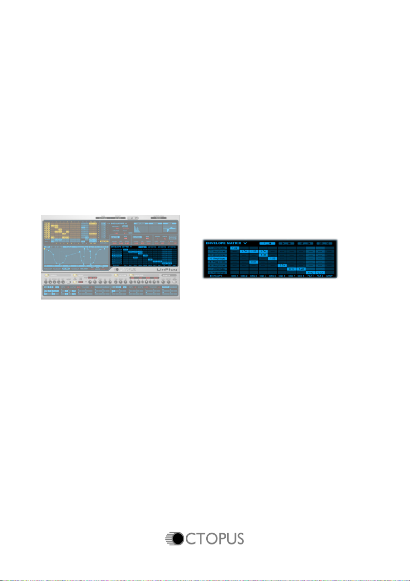
Envelope Matrix
Envelopes are routed to modulation destinations using the Octopus'
Envelope Matrix module which is located on the middle-right of the
instrument's front panel.
The Envelope Matrix module is similar to the Oscillator Matrix module
described above, so that if you know how that module works you should
have no trouble with the Envelope Matrix module. Note that the Envelope
Matrix module works in conjunction with the Envelope Editor module so it's
important that you are familiar with both modules in order to get the most
out of the Envelope Matrix module.
The Octopus contains 32 envelopes arranged in 4 banks of 8 slots. At any
time, one or more of these envelopes acts as a modulation source. The
Envelope Editor displays the currently selected envelope.
The Envelope Matrix contains an array of nodes connecting Envelopes to
various destinations within the synthesizer. The envelopes are displayed as
a set of vertical slots on the left side of the module. Envelope destinations
are displayed horizontally across the bottom of the matrix. Note that the
generic envelope destination is set in the Envelope Editor module (see
above for more information about the Envelope Editor module), while the
actual destination is set in the Envelope Matrix module. 11 destinations are
available. These are: Oscillator 1 to Oscillator 8, Filter 1 and Filter 2, and
the Sampler.
Manual 29
Page 32

Envelope Bank Select/Envelope Select
Clicking on the Envelope Bank control selects one of the four envelope
banks. Clicking on one of the Envelope Selector controls selects the
envelope. The currently selected bank and envelope are highlighted.
Envelope Editor Menu
The Envelope Editor popup menu is used for adding and removing
envelopes from the Matrix, as well as editing envelopes, and particularly for
interchanging envelope settings between different Envelopes. The menu is
accessed by clicking on the V symbol beside the Envelope Matrix label. The
popup menu contains ten items: Add Envelope, Delete Envelope, Move Up,
Move Down, Copy View, Paste View, Reset View, Clone Envelope, Load
Envelope and Save Envelope.
Envelopes are added and removed from the instrument using the Add
Envelope/Delete Envelope menu items. When an envelope is added to the
instrument it is placed in the next available slot in the Envelope Selector
and is selected as the current envelope. When an envelope is removed
from the instrument the envelopes compact down and the envelope
following the deleted envelope becomes the active envelope.
The Move Up/Move Down menu items move the currently active envelope
one position up or down in the envelope slot array. This is useful for
grouping similar types of envelope (for example, amplitude envelopes)
together.
The Copy View and Paste View menu items are used for exchanging
envelopes between different envelope slots. The Copy View menu item
copies the currently selected envelope's settings into memory, while the
Paste View menu item pastes the settings currently stored in memory into
the selected envelope slot. The Reset View menu item clears the
envelope's current parameters and resets them to their default settings.
Note that the Copy View, Paste View and Clear View items only affect the
envelope that is currently displayed in the editor. This applies to the KBD
and VEL envelopes as well. As a result, if you select Copy View and have
ENV selected as the view option, only envelope points will be copied, but
not velocity or keyboard scaling points. The same applies to Paste View
and Clear View.
30 Manual
Page 33

Also note that one type of envelope point (ENV/KBD/VEL) cannot be
transferred to a different type of envelope. For example, you cannot copy a
KBD Scaling envelope to an ENV envelope.
The Octopus has 2 independent memory buffers, one for the ENV envelope
and another for the KBD/VEL envelopes. This means that if you copy new
ENV points to buffer, any KBD/VEL points that have already been copied
won't be changed or erased. But note again, you may not copy KBD and
paste it to VEL, as well as copy VEL and paste to KBD.
The Clone menu item copies an envelope, including the ENV, KBD, VEL
envelopes as well as the corresponding matrix values, and creates a new
identical envelope in the slot after the existing envelope. Envelopes in slots
after the source envelope are shifted one position in the envelope slot array
to make way for the new envelope.
The Load menu item allows envelopes to be loaded into an envelope slot.
The Save menu item allows envelopes to be saved which means you can
create sets of envelopes (for example, a set of different LFO-style
envelopes). The Octopus comes with a set of Envelopes that you can use
for modulation within your own presets.
Matrix Nodes
The amount of signal sent to a particular destination is determined by the
setting of the Matrix node. When the signal level is set to 0.0 the node is
deactivated and no signal is sent to the destination. The destination value is
set by clicking on the node and dragging the mouse vertically. The range of
values available depends upon the envelope type (which is set in the
Envelope Editor module). It is important to note that the value set in the
node is a scaling value that is multiplied by the envelope to produce the
destination modulation value.
Manual 31
Page 34

Effects
The Octopus has 4 independent, simultaneously-available stereo effects
modules units. These are Chorus, Delay, Reverb and Equalizer. The four
effects units are located in the Effects module which is located towards the
lower edge of the instrument's front panel.
Effects processing occurs in a left-to-right order which means that the
signal path is as follows: Chorus -> Delay -> Reverb -> Equalizer.
The Power button at the top left of each effects unit is used to set the unit's
status. This can be either On or Off. When the Effects unit is On, the Power
button has a yellow backlight, while when the Effects unit is Off the button's
backlight is darkened. Clicking on the button switches the Effects unit on
and off. When the effects unit is switched off audio passes through it
without being processed.
Each effect's controls differ. All effects are described in detail below.
Chorus
The Chorus effect is located at the far left of the Effects module. This effect
can be used to thicken a single sound creating the impression that it
contains multiple voices. The Chorus works by mixing delayed signals with
the original signal. The Octopus's Chorus features controls for Time,
Speed, Stereo, Dry, Wet and Invert.
32 Manual
Page 35

The Time control is used for setting the chorus' delay time. Longer delay
times produce a chorusing effect while shorter times create a flanging
effect. The SPD (Speed) dial sets the rate at which the signal is modulated.
The Stereo control is used to adjust the width of the stereo image. To
create the maximum stereo effect set the control to its maximum value.
Note that when used in combination with other stereo enhancing effects
(such as the Delay) it might be desirable to set the Stereo control to a lower
value.
The Dry control allows you to set the level of the original unprocessed or dry
signal that is sent from the effects unit. This control is useful for controlling
the balance between the effect's processed and unprocessed output
signals.
The Wet control allows you to set the level of the processed or wet signal
that is sent from the effects unit. This control is useful for controlling the
balance between the effect's processed and unprocessed output signals.
The Invert control is inverts the phase of the effect's Wet signal. This can
be used to produce a different type of chorusing effect.
Delay
The Delay effect is located to the right of the Chorus effect. This effect can
be used to create echoes that bounce around the stereo field. The Delay
features controls for: TMP Sync, Time Pre, Time Left, Time Right, L, (Pan
Left), R (Pan Right), FDBK (Feedback), Bal (Balance) and Wet.
Manual 33
Page 36

The Delay functions as follows: the input signal is first delayed by Time Pre
amount, then it’s delayed by Time Left amount and finally by the Time Right
amount. If Feedback is applied, the Time Right signal is fed back into the
left delay line, so that an alternating left-right delay is produced. The Bal
(Balance) and Wet controls set the mix between the original unprocessed
signal and the delayed signal.
The TMP Sync control synchronises the effect's delay times with the song's
current tempo. When the TMP Sync control is OFF the effect's delay times
are shown in milliseconds. When the TMP Sync control is ON the effect's
delay times are shown in quarter notes. In this case, the actual delay time
depends on the current song's tempo.
The Time Pre, Time Left and Time Right controls are used for setting the
centre, left and right channel delay times. The Time Pre control sets the
delay time of the centre delay while the The Time Left and Time Right
controls set the delay times of the left delay and right delay. The delay time
is displayed as either milliseconds or quarter notes depending on the
current setting of the TMP Sync control. When the TMP Sync control is OFF
all three delays have a range of 1 ms to 1300 ms. When the TMP Sync
control is ON all three delays have a range of 0.00 to 8.00 quarter notes.To
edit one of the delay times click on the numerical display and drag the
mouse up or down.
The L (Pan Left) and R (Pan Right) controls are used to set the pan position
of the Time Left and Time Right delay signals.
Hint: If you want the delayed signal to appear on the right side first, use the
Pan controls to exchange left and right positions.
The FDBK (Feedback) control sets the number of times the signal repeats
or echoes.
The Bal (Balance) control is used to set the balance between the pre delay
and the left and right delays. Turning the Bal control completely anticlockwise means that only the Time Pre delay signal is sent from the effects
34 Manual
Page 37

unit. Turning the Bal control completely clockwise means that only the Time
Left/Time Right signals are sent from the effects unit. Intermediate settings
produce a mixture of the three signals.
The Wet control allows you to set the level of the processed or wet signal
that is sent from the effects unit. This control is useful for controlling the
balance between the effect's processed and unprocessed output signals.
Reverb
The Octopus' Reverb effect is used to add ambiance to sounds. It features
controls for: FDBK (Feedback), Bright and Wet.
The FDBK (Feedback) control is used to set the effect's reverb time. This
parameter approximately corresponds to the size of the simulated space.
Turning the control completely anti-clockwise produces effects similar to the
resonances of very small spaces like tubes or pipes. Turning the control
completely clockwise produces effects similar to the resonances of very
large spaces like large auditoriums or churches.
The brightness of the space is controlled with the effect's Bright control. In
practical terms, the brightness of a space is determined by type and amount
of damping present in the space. For example, carpeted rooms will sound
darker than rooms containing a lot of glass surfaces which tend to sound
brighter. In the case of the Octopus, the higher the effect's Bright setting,
the larger the amount of high frequency content in the processed signal.
The Wet control allows you to set the level of the processed or wet signal
that is sent from the effects unit. This control is useful for controlling the
balance between the effect's processed and unprocessed output signals.
Manual 35
Page 38

Equalizer
The Octopus’ (Parametric) Equalizer effect can be used to accentuate or
remove selected parts of the signal's spectrum. The effect features four
separate bands. Each band has controls for Frequency, G (Gain) and Q
(Quality).
The Frequency control is used to set the centre frequency at which the filter
band operates. To set the centre frequency click on the numerical display
and drag the mouse up or down. The available range is 30 Hz to 20,267 Hz.
The G (Gain) control is used to set the gain of the selected frequency band.
When the control is set to the middle position no gain is applied to the
frequency band. If the control is turned left then the signal will be cut. The
closer the control to the leftmost setting the more the signal will be cut. If
the control is turned right then the signal will be boosted. The closer the
control is set to rightmost the more the signal will be boosted. The range is
-24dB...0dB...+24dB.
The Q or Quality control is used to set the width of the band that is cut or
boosted. Increasing the value of the Q control makes the band affected by
the filter narrower and therefore, more pronounced.
36 Manual
Page 39

Master
The Octopus' Master module is located on the lower right of the
instrument's front panel. The Master module contains three controls: Gain,
Distortion and LoFi Waves. These are described below.
Gain
The Gain control is a final scaling factor that can be used to either boost or
cut the overall output of the instrument.
Distort
The Octopus features a tube-like distortion effect that can be used for
adding warmth to sounds. The effect is controlled using the Distort
(Distortion) control. Turning the control in a clockwise direction adds more
distortion to the signal.
LoFi Waves
The LoFi Waves control is used to set the accuracy of the Octopus' signal
generation. When the LoFi Waves control is switched on the following
effects occur: lower quality waveforms are used for signal generation,
waveform interpolation is less accurate and waveforms are stored in less
memory. This is useful if you're trying to replicate the sounds of an early FM
synthesizer.
Manual 37
Page 40

Step Sequencer
The Octopus features two identical Step Sequencers. These allow you to
create patterns of notes that are played back as part of the current preset.
The Step Sequencers are located at the lower edge of the instrument's front
panel.
Each Step Sequencer contains the following controls: Seq 1/Seq 2, Menu,
Steps, Shuffle, Transpose, Pattern Display, Random and Ping Pong. These
controls are described below. Note that each Step Sequencer is identical so
only one will be described in this manual. Also note that each pattern is
considered to be part of the preset, so that if you change presets and the
pattern has not been saved with the preset, then it will be lost.
Seq 1/Seq 2
The Seq 1/Seq 2 buttons are located at the top left of each Step Sequencer
module. Clicking on these buttons turns the respective Step Sequencer on
or off.
38 Manual
Page 41

Menu
Each Step Sequencer module has a drop-down Pattern menu. This menu is
accessed by clicking on the V beside each Sequencer's label.
The menu contains the following items: Load Pattern, Save Pattern, Clear
Pattern, Shift Left, Shift Right and Reverse.
The Load Pattern menu item enables you to load a pattern into the Step
Sequencer. The Save Pattern menu item enables you to save a pattern so
that it can loaded at a later point in time. The Load Pattern and Save
Pattern menu items enable you to create a library of patterns that can be
used with different sounds. The Clear Pattern menu item resets the Step
Sequencer to its default values and clears the current pattern from the
display.
The Shift Left and Shift Right menu items shift the current pattern either
right or left depending on the item selected. For example, the pattern 0 – 2
– 4 – 5 becomes 2 – 4 – 5 – 0 which is the original pattern shifted one place
to the left.
The Reverse menu item reverses the order of the pattern. For example, a
pattern such as 0 – 2 – 4 – 5 becomes 5 – 4 – 2 – 0.
Note that items in the Pattern menu change the pattern itself. This is
different from, say, the PingPong switch which changes the way that the
pattern plays back, but not the pattern itself.
Steps
The Step control allows you to define length of the pattern that the Step
Sequencer plays. A pattern can range from a 1-step sequence to a 32-step
sequence.
Manual 39
Page 42

Shuffle
The Shuffle control adds a swing value to the pattern's notes so that within
a given clock interval the odd step numbers (notes) are lengthened and the
even ones are shortened (or vice versa). It is much easier to hear this effect
than to explain it. To hear the effect, create a pattern of 4 steps and then
vary the Shuffle parameter. The change in the rhythm of the pattern should
be clearly audible.
Transpose
The Transpose control enables the pitch of the entire pattern to be
transposed over a range of +- 24 semitones.
Random
The Random control is a playback parameter that determines the order and
timing in which pattern notes are played back. Note that the effect of the
Random control is not shown on the Pattern Display. When the control is
ON it sets pattern playback so that it randomly plays back notes that are
part of the current pattern. Note that the timing of the notes also is
randomised.
Ping-Pong
The Ping-Pong control is a playback parameter that determines the order in
which notes are played back. Note that the effect of the control is not shown
on the Pattern Display. When the control is ON it sets the pattern playback
so that it first plays the pattern in the forwards direction, and then plays the
pattern in reverse order. Note that the steps at the end of the pattern are
not repeated. For example, the pattern 1_2_3_4 would play back as
1_2_3_4_3_2_1_2_3...
40 Manual
Page 43

Pattern Display
The key component of the Octopus' 2 Step Sequencers is their Pattern
Displays. The Pattern Displays show the settings for each step (or note)
within the pattern. Pattern Steps are edited by left-clicking and dragging on
them. A Pattern Step can be set to its default value by right-clicking on it. In
this case, the step is set to OFF.
Each step has the following range of values: -24...OFF, SUS, 0...+24. The
numerical value of a step indicates its pitch relative to the pitch of the input
source. For example, a value of 5 sets the pitch of the step to 5 semitones
higher than that of the input source. Setting the step to OFF makes it
inactive, while setting it to 0 means that the step will have the same note
value as the input source. Setting the step to SUS ties the step to the value
of the previous step creating a sustained note.
Manual 41
Page 44

Unison/Glide
The Octopus' Unison/Glide module contains a group of controls related to
the instrument's polyphonic capabilities as well as its portamento settings.
The Unison/Glide module is located on the right side of the front panel
below the waveform display and above the Envelope Matrix.
The Unison/Glide module contains the following controls: Transp
(Transpose), Voices, Unison, Porta (Portamento), Slide, Detune and Bend
Up/Bend Down. These controls are described below.
Transp (Transpose)
The Transpose control is used to set the overall pitch (in semitones) of the
instrument relative to the input trigger. For example, if the Transpose
control is set to 5, then the entire instrument's output will be transposed
upwards by 5 semitones. The available range is -24 to +24 semitones.
Voices
The Voices control is used to set the number of voices (otherwise known as
polyphony) available within the instrument. The Voices control has a range
of 1 to 12 voices.
Unison
The Octopus has a Unison mode in which the instrument's oscillators are
detuned to create extremely fat, rich sounds. When in Unison mode, the
42 Manual
Page 45

synth becomes monophonic and it is only possible to play one note at a
time. The Unison button is used to switch the Octopus' Unison mode on
and off.
Detune
The Unison button is used in conjunction with the Detune control. When the
value of the Detune control is increased the instrument's Oscillators are
gradually detuned. The greater the detuning, the more the sound is
thickened. The available range is from 0.00 to 1.00. Note that the setting of
the Voices control (described above) determines the number of voices that
are used in Unison mode.
Glide
The Glide control sets the rate at which the instrument's pitch moves from
one note to that of the following note. A value of 0 means that Glide is
deactivated. A Glide value greater than 0 means that every note glides up
or down in pitch from the previously played note within a fixed time period.
The higher the value of the Glide control, the longer the transition time
between notes. Note that the Legato switch changes this behaviour
depending on the way the note is played.
Legato
The Legato switch controls the way that overlapping notes are played by the
instrument. The Legato switch only affects playback when the Glide control
is set to a value greater than 0. When switched OFF, all notes will glide
from the previously played note to the following note regardless of whether
they overlap or not. When switched ON, only legato notes (that is, notes
where the end of the previous note overlaps the start of the following note)
will glide from one to the other. This makes it possible to apply Glide to
selected notes.
Bend
The settings of the Bend controls determine the manner in which the
Octopus responds to MIDI pitch bend messages. The Bend control is made
up of two components: the Bend Up control and the Bend Down control.
These controls are indicated by the ^ and v symbols either side of the Bend
label. Each range can be set from 0 to 48 semitones.
Manual 43
Page 46
Miscellaneous
Several additional controls are available within the Octopus. These are the
Bank/Preset Browser controls, the File controls and the Microtuning control.
These three sets of controls are located at the top edge of the instrument's
front panel.
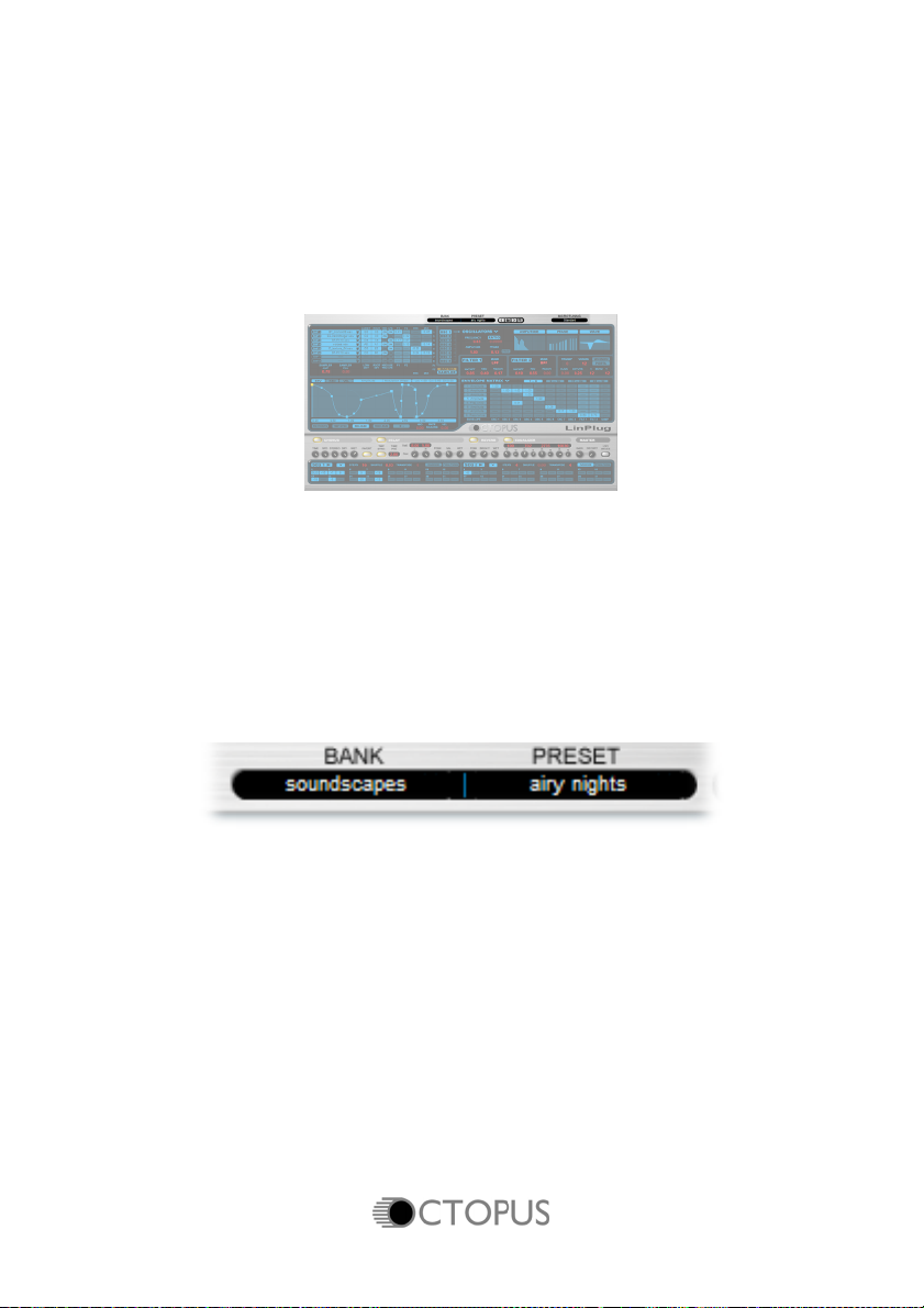
Bank/Preset
The Bank/Preset Browser controls are located at the top of the front panel.
The Bank/Preset Browser consists of a two-part editable display.
The Bank display on the left shows the current bank and the Preset display
on the right part shows the current preset. By default the Browser points to
the factory presets installed with the Octopus.
Presets can be changed directly in the Bank/Preset Browser by clicking on
either the Bank or the Preset display. Clicking on the Bank display opens a
menu enabling you to load groups of sounds by Bank. Clicking on the
Preset display opens a menu enabling you to load individual presets.
44 Manual
Page 47

File Controls
The File Controls are used for all File-related operations.
The Load button (shown as a folder icon) opens a dialog that lets you select
a file for loading. The Previous and Next buttons (the < and > symbols
either side of the Load button) allow you to traverse all Octopus presets
within the current folder. The Save button (shown as a disk icon) allows you
to save the current preset settings.
The settings of all sections, including the Volume setting, are saved with the
preset. The Octopus loads and saves all of its presets directly to hard disk
so your computer's RAM does not limit the number of available presets.
Microtuning
The Microtuning control opens a menu that enables the Octopus to be
tuned to tunings other than Equal Temperament.
See Appendix A for a complete description of how to use TUN files to set
the Octopus’ tuning.
LinPlug/Octopus Logos
Clicking on either the LinPlug or the Octopus logos in the middle right of the
Octopus’s Main panel opens the instrument’s Rear Panel. The Rear Panel
displays the version of the instrument.
Manual 45
Page 48
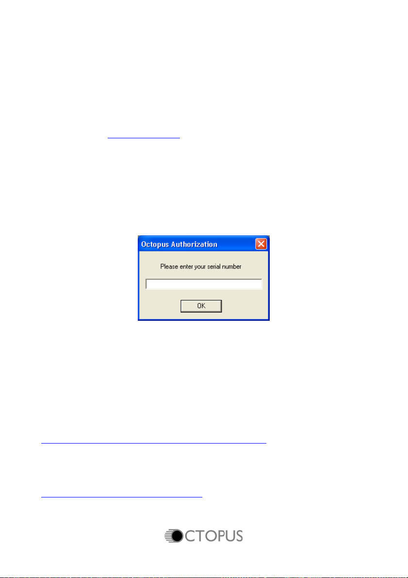
Registration
You can use the demo version of the Octopus for evaluation purposes for a
period of up to 30 days. If you then decide that you would like to keep using
the Octopus you must register your demo version.
Registering the Octopus is very easy. All you have to do is visit the LinPlug
online shop at www.linplug.com
credit card transaction has been authorized you will be sent a personal
serial number. In most cases this will only take a few minutes. You will then
be able to download the full version of the Octopus.
After you've downloaded and installed the full version of the Octopus, open
your host program and then load the Octopus. As the Octopus loads the
authorization window shown below will appear:
and purchase a license. As soon as your
Enter the serial number you have received into the edit box and then click
the OK button. The Octopus is now registered.
If the serial number has not been entered or it has been entered incorrectly,
a warning will appear and the Octopus will revert to the demo version.
If you did not purchase the Octopus directly from LinPlug please register the
instrument at:
http://www.linplug.com/Support/Register/register.htm
If you have any questions regarding the Octopus’ registration process
please contact us at:
www.linplug.com/support/support.htm
46 Manual
Page 49

Optimizing CPU Usage
Software synthesizers are highly CPU-intensive. The real-time calculation of
audio waveforms, filters, effects and modulators places a significant load on
the host computer's CPU.
As such, the main limiting factor in software synthesizer performance is
CPU processing power. Each additional oscillator, filter, effect and
modulator that is included in an instrument adds to the CPU load. As a
result, it's best to switch off any unused units within the Octopus to
conserve CPU resources.
It may also be useful to use the send effects of your host’s mixer instead of
Octopus's effects as they are shared among all instruments.
Manual 47
Page 50

Glossary
Amplifier: A signal processing device that changes the
amplitude, and hence the volume, of a signal.
Effect: A signal processing device that changes some
aspect of the input signal. An enormous number of
different effect types are available. These include
Chorus (which produces a thickening of the signal),
Delay (adding echoes to the signal) and Distortion
(which changes the shape of the waveform usually
adding overtones).
Envelope: A time-varying signal used to control the
development of another signal after it has been
triggered. Envelopes are most often used for
controlling a signal's amplitude. The shape of the
envelope is determined by the number of control
parameters.
Filter: A signal processing device that suppresses or
filters out specific parts of a signal's frequency
spectrum. Numerous types of filter are used in
audio synthesis. These include Low Pass, High
Pass, Band Pass and Notch. The tone controls on
a stereo amplifier are one example of an audio
filter.
FM: FM or Frequency Modulation is a process where
the frequency of one oscillator (the carrier) is
controlled by another (the modulator). When the
frequency of the modulator is periodic and below
the audio range (less than 20 Hz) vibrato is
produced. When the modulation frequency is within
the audio range, Frequency Modulation is
produced.
Harmonic: A harmonic is a signal whose frequency is an
integral (whole-number) multiple of a reference
frequency. The term can also refer to the ratio of
the frequency of such a signal to the frequency of
48 Manual
Page 51

the reference signal. For example, a 100 Hz tone
has harmonics at 200 Hz, 300 Hz and so on.
LFO: An LFO or Low Frequency Oscillator is a periodic
signal source (usually below audio frequency
range) used to modulate another signal parameter.
An LFO can be used for a variety of effects
including vibrato (by modulating the pitch) and
tremolo (by modulating the volume).
Microtuning: See Appendix A for a detailed description.
Matrix: A signal junction where a source signal can be
patched so that it controls a destination signal. The
Octopus's Envelope Matrix is used for tasks such
as modulating a generator's amplitude by an
Envelope.
Oscillator: A signal source that generates a waveform at a
given frequency.
Phase: Phase defines the position of a point within a
waveform cycle. If a complete waveform cycle is
defined as having 360 degrees, then a phase shift
of 90 degrees moves the point one quarter of the
way along the waveform.
Sequencer: A sequencer is a device that can be used to record
and play back musical control data.
Manual 49
Page 52

MIDI Implementation Chart
Product: LinPlug Octopus Version 1.x Date: 4.Dec 2005
Manufacturer LinPlug Virtual Instruments GmbH
Function Transmitted Recognized Remarks
Basic Channel
Mode
Note Number
Velocity
Aftertouch
Pitch Bend no yes
Control Change no yes
Program Change no no
System Exclusive no no
System Common
Default no no
Changed no no
Default no Omni
Changed no no
no yes
True Voice no no
Note On no yes
Note Off no no
Poly (Key) no yes
Mono (Channel) no yes
Song Position no no
Song Select no no
Tune Request no no
System Realtime
Commands no no
Aux Messages
Clock no no
Local On/Off no no
All Notes Off no yes
Active Sensing no no
System Reset no yes
50 Manual
Page 53

Appendix A: Using TUN files in the Octopus
By Jacky Ligon
About Microtuning
Microtuning, or 'microtonality' are methods for tuning musical instruments,
whereby musicians may explore and compose with ethnic, historical and
contemporary intonation systems. Microtuning musical instruments enables
musicians to use unique scales which may have pitches lying between the
notes of our familiar Western 12 tone equal tempered scale. These unique
pitches and methods of microtuning musical instruments to sounds found in
the 'cracks' of the 12 Tone Equal Temperament, are one of the things that
gives the music of such places as Bali, India, Africa, Thailand, Turkey and
the Middle East a special intonational flavor, but is also something that is of
immeasurable value to the contemporary acoustic and electronic composer,
who may require a more broad palette of musical pitches for their music.
The quest for creating beautiful and musically useful microtuning systems
has been an unending process of discovery and debate amongst musical
theorists, mathematicians, physicists and musicians going back to early
history. Quite often the reasons for microtuning musical instruments may
involve improving the consonant intervals of a tuning-system for sweeter
sounding harmonies, as well as offering a wider variety of choices for
melody. Microtuning an instrument can sometimes mean there may be less,
or more than 12 tones in an octave, or even that the octave itself may be
stretched or compressed. Microtuning is a vast musical frontier, rich with
historical lore, music and an infinity of exciting musical possibilities for the
adventurous sonic explorer.
Creating TUN microtuning files with SCALA
Scala is a freeware utility developed by Manuel Op de Coul in the
Netherlands, which can be used for the creation and analysis of historical,
ethnic and contemporary microtunings. A powerful capability of Scala is that
it enables the user to create the proprietary tuning data required for
microtuning a wide range of hardware and software synthesizers and
samplers.
Manual 51
Page 54

Scala may be used to create the TUN format microtuning files needed to
explore microtunings with this software instrument.
The Scala home page is http://www.xs4all.nl/~huygensf/scala/
Specifying the Reference Frequency of a Microtuning
One of the powerful capabilities of the TUN file format and Scala, is the
ability to specify the frequency and MIDI-Note which will become the
reference pitch, or starting note for a microtuning. This becomes a very
important consideration when one is using a number of different
synthesizers and wishes to keep them in all tune with a given base
frequency. It is very common for a musician to need to specify a certain
concert pitch such as A440 Hz (MIDI-Note 69) or C261.6256 Hz (MIDI-Note
60) as a reference for a microtuning, however, the flexibility of the TUN
format and Scala enables one to specify this frequency arbitrarily, so that
any chosen starting frequency may be assigned to any desired MIDI-Note.
In Scala this reference is called the Map Frequency.
Being able to specify a particular MIDI-Note reference and its associated
Map Frequency on the MIDI controller, provides a way to map a microtuning
to begin on any desired MIDI key, making it easier to navigate the
instrument when there may be more or less than 12 tones per octave, or
where one may have a musical need to map the notes of a microtuning to
fall on certain physical keys.
52 Manual
Page 55
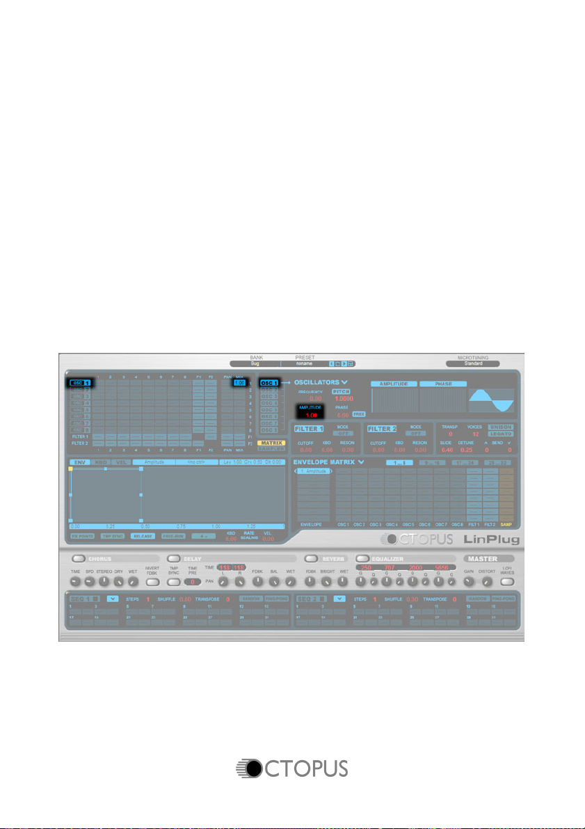
Tutorial: Programming your own patches
If you can't wait to get started programming your own Octopus presets,
here's a tutorial explaining how to create a simple FM patch using two
oscillators, an amplitude envelope and a filter. The following tutorial
certainly doesn't cover all aspects of the instrument. If you're looking for
more detailed information on any particular aspect of the Octopus then
you'll need to consult the appropriate section in the manual. Let's get
started...
1. Switch on Osc 1 on the top left of the Oscillator Matrix.
2. Set Osc 1's Mix parameter (on the far right of the Oscillator Matrix)
to 1.0.
3. Set Osc 1's Amplitude (in the Oscillator Editor section) to 1.0.
4. If you now trigger the instrument it will play a sine tone!
Manual 53
Page 56

To make the sound more interesting, we'll now change the spectrum of the
Oscillator. This can be done in two ways: statically using the Harmonic
Amplitude Editor in the Oscillator Editor section (this produces a fixed
change in the waveform shape), or using Frequency Modulation in the
Oscillator Matrix section (this produces a dynamic change in the
waveform's shape).
5. Move the mouse to the Harmonic Amplitude Editor. The amplitude
of each of the waveform's 32 harmonics can be set by clicking and
dragging in the Editor. The results of the editing are displayed in the
Waveform display to the right of the editor.
54 Manual
Page 57

6. Alternatively, a second Oscillator can be used to modulate Osc 1.
Switch on Osc 2, set its Amplitude to 1.0 but don't send its output to
the Mix. Instead, set it up to modulate Osc 1 by increasing the value
in second row of the first column of the Oscillator Matrix (as shown
below). The setting of this Matrix node determines the amount of
signal that is sent from Osc 2 to Osc 1, and hence the amount that
Osc 1 is modulated by Osc 2. This produces an effect known as
Frequency Modulation resulting in rich, complex timbres.
Manual 55
Page 58
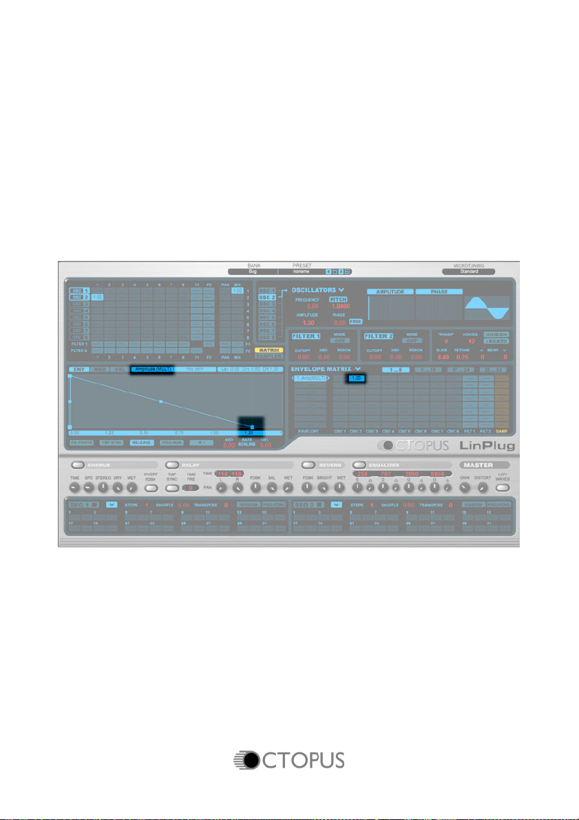
To make the sound change dynamically you need to modulate it. In the
Octopus, Envelopes are the key to modulation. As an example, we'll
modulate Osc 2.
7. In order to modulate a destination with an envelope, you need to
assign an envelope type to the envelope. In this case, change the
type of the envelope shown in the Editor to Amplitude Multiplication
and then set the endpoint to a level of 0. The envelope also needs
to be given a specific destination (the envelope type is only a
generic destination). Move to the first row, second column of the
Envelope Matrix and set the value of the node to 1.0. The envelope
now modulates the amplitude of Osc 2.
56 Manual
Page 59

As you may have already guessed, the same process can also be applied
to Oscillator 1 to control the overall Amplitude of our sound.
8. Add an envelope to the Envelope Matrix by clicking on the V beside
the Envelope Matrix label. Choose Add Envelope from the menu
and change the type to Amplitude Mult, and then assign it to Osc 1.
Note that 32 envelopes are available in 4 banks of 8 envelopes.
The currently active envelope is highlighted. This time, we'll try to
be a little bit creative about where we place the envelope points. Try
to copy the envelope shape shown below—you don't need to be too
exact, just something roughly similar will do.
Manual 57
Page 60
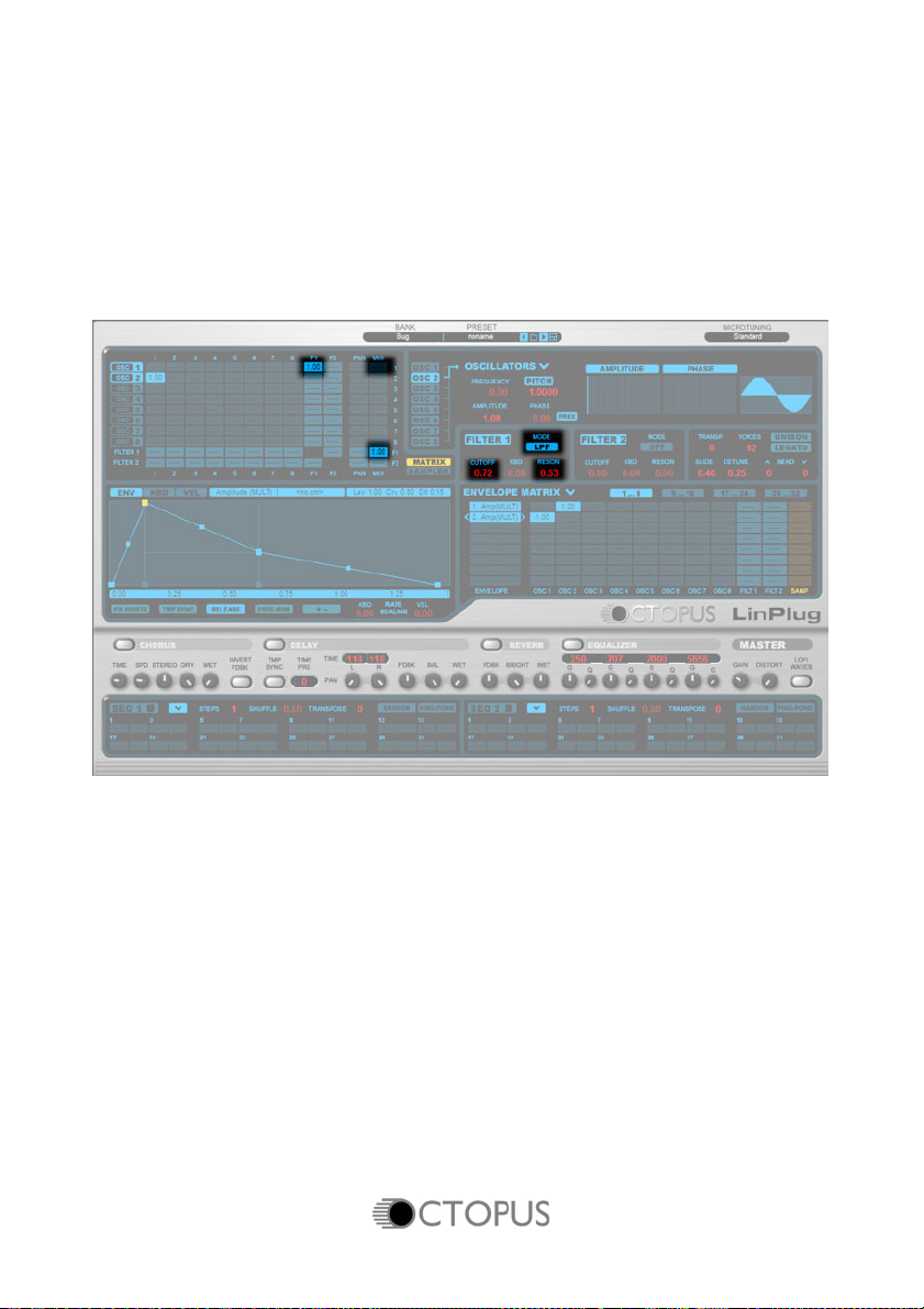
Next we'll add some filtering to the patch.
9. To incorporate a filter into the patch, first change the settings in the
Oscillator Matrix so that Osc 1 is no longer routed directly to the Mix
but instead is sent to Filter 1.
10. Set the output of Filter 1 to the Mix.
11. Set up the Filter to the desired type and values as shown below.
58 Manual
Page 61
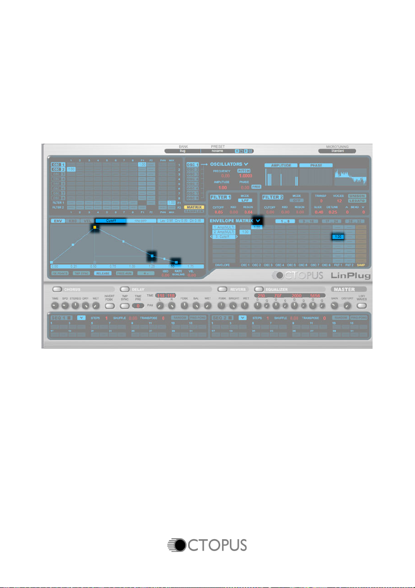
Again, the sound is more interesting if it's animated, so we'll use an
envelope to modulate the filter's cutoff frequency.
12. Create a new envelope.
13. Set the type to Cutoff.
14. Assign it to Filter 1 in the Envelope Matrix
15. Edit the envelope to a suitable shape.
Congratulations!
You have successfully created your first Octopus patch. Of course, you've
barely scratched the surface of the Octopus' capabilities. If you're interested
in understanding how the Octopus works in more detail then consult the
appropriate sections of this manual.
Manual 59
Page 62

 Loading...