

LINKSYS WRV54G Users Manual

A Division of Cisco Systems, Inc.
®
2.4
Model No.
GHz
54Mbps
WIRELESS
WRV54G
Wireless-G
VPN Router
Linksys is a registered trademark or trademark of Cisco Systems, Inc.
and/or its affiliates in the U.S. and certain other countries.
User Guide

Dual-Band Wireless Access Point
Table of Contents
Chapter 1: Introduction 1
Welcome 1
What’s in this Guide? 2
Chapter 2: Planning your Wireless Network 3
Network Topology 3
Roaming 3
Network Layout 4
Chapter 3: Getting to Know the Access Point 5
The Back Panel 5
The Front Panel 5
Chapter 4: Connecting the Access Point 8
Hardware Installation 8
Chapter 5: Setting Up the Access Point 11
Setup Wizard 11
Chapter 6: Configuring the Access Point 15
Overview 15
The Setup Tab 16
The Password Tab 17
The Status Tab 18
The Help Tab 18
The Filter Tab 19
The Wireless Tab 20
Appendix A:Troubleshooting 22
Frequently Asked Questions 22
Appendix B: Wireless Security 26
A Brief Overview 26
What Are The Risks? 26
Appendix C: Upgrading Firmware 33
Appendix D: Windows Help 34
Appendix E: Glossary 35
Appendix F: Specifications 39

Dual-Band Wireless Access Point
Appendix G: Warranty Information 41
Appendix H: Regulatory Information 42
Appendix I: Contact Information 44

Dual-Band Wireless Access Point
List of Figures
Figure 1-1: 1
Figure 1-2: 1
Figure 1-3: 2
Figure 1-4: 2
Figure 1-5: 2
Figure 1-6: 2
Figure 1-7: 2
Figure 1-8: 2
Figure 1-9: 2
Figure 1-10: 2
Figure 1-11: 2
Figure 1-12: 2
Figure 2-1: Network 4
Figure 2-2: 4
Figure 2-3: 4
Figure 2-4: 4
Figure 2-5: 4
Figure 2-6: 4
Figure 2-7: 4
Figure 2-8: 4
Figure 2-9: 4
Figure 2-10: 4
Figure 2-11: 4
Figure 2-12: 4
Figure 3-1: Back Panel 5
Figure 3-2: Front Panel 6
Figure 3-3: 7
Figure 3-4: 7
Figure 3-5: 7
Figure 3-6: 7
Figure 3-7: 7
Figure 3-8: 7
Figure 3-9: 7
Figure 3-10: 7
Figure 3-11: 7
Figure 3-12: 7
Figure 4-1: 9
Figure 4-2: 9
Figure 4-3: 9
Figure 4-4: 9
Figure 4-5: 9
Figure 4-6: 9
Figure 4-7: 9
Figure 4-8: 9
Figure 4-9: 9
Figure 4-10: 9
Figure 4-11: 9
Figure 4-12: 9
Figure 5-1: Welcome 11
Figure 5-2: Connecting 11
Figure 5-3: 11
Figure 5-4: 12
Figure 5-5: 12
Figure 5-6: 12
Figure 5-7: 12
Figure 5-8: 12
Figure 5-9: 12
Figure 5-10: 12
Figure 5-11: 12
Figure 5-12: 12

Dual-Band Wireless Access Point
Figure 5-13: 12
Figure 5-14: 12
Figure 5-15: 12
Figure 6-1: Password Screen 15
Figure 6-2: Setup Tab 16
Figure 6-3: 802.11b Wireless Setings 17
Figure 6-4: Password Tab 17
Figure 6-5: Status Tab 18
Figure 6-6: Help Tab 18
Figure 6-7: Filter Tab 19
Figure 6-8: Wireless Tab 20
Figure 6-9: 21
Figure 6-10: 21
Figure 6-11: 21
Figure 6-12: 21
Figure 6-13: 21
Figure 6-14: 21
Figure 6-15: 21
Figure B-1: Warchalking 26
Figure B-2: 802.11a WEP Key Setting 32
Figure B-3: 802.11b WEP Key Setting 32
Figure C-1: Upgrade Firmware 33

Wireless-G Broadband VPN Router
Chapter 1: Introduction
Welcome
Wireless-G is the upcoming 54Mbps wireless networking standard that’s almost five times faster than the widely
deployed Wireless-B (802.11b) products found in homes, businesses, and public wireless hotspots around the
country—but since they share the same 2.4GHz radio band, Wireless-G devices can also interoperate with
existing 11Mbps Wireless-B equipment.
Since both standards are built in, you can protect your investment in existing 802.11b infrastructure, and migrate
to the new screaming fast Wireless-G standard as your needs grow.
The Linksys Wireless-G Broadband VPN Router is really three devices in one box. First, there’s the Wireless
Access Point, which lets you connect Wireless-G or Wireless-B devices to the network. There’s also a built-in 4port full-duplex 10/100 Switch to connect your wired-Ethernet devices. Connect four PCs directly, or daisy-chain
out to more hubs and switches to create as big a network as you need. Finally, the Router function ties it all
together and lets your whole network share a high-speed cable or DSL Internet connection.
To protect your data and privacy, the Wireless-G Broadband VPN Router can encrypt all wireless transmissions.
The Router can serve as a DHCP Server, has NAT technology to protect against Internet intruders, supports VPN
pass-through, and can be configured to filter internal users’ access to the Internet. Configuration is a snap with
the web browser-based configuration utility.
With the Linksys Wireless-G Broadband VPN Router at the center of your home or office network, you can share a
high-speed Internet connection, files, printers, and multi-player games with the flexibility, speed, and security
you need!
Chapter 1: Introduction
Welcome
1
Dual-Band Wireless Access Point
Chapter 2: Planning your Wireless Network
The Router’s Functions
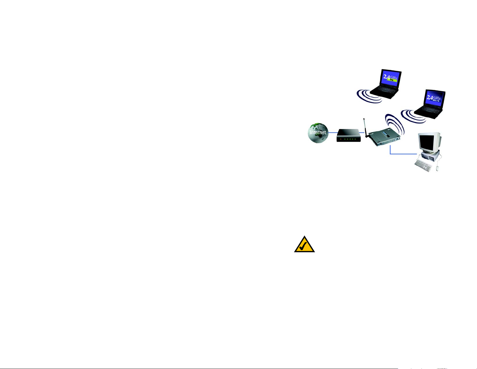
Simply put, a router is a network device that connects two networks together.
In this instance, the Router connects your Local Area Network (LAN), or the group of PCs in your home or office , to
the Internet. The Router processes and regulates the data that travels between these two networks.
The Router’s NAT feature protects your network of PCs so users on the public, Internet side cannot “see” your
PCs. This is how your network remains private. The Router protects your network by inspecting every packet
coming in through the Internet port before delivery to the appropriate PC on your network. The Router inspects
Internet port services like the web server, ftp server, or other Internet applications, and, if allowed, it will forward
the packet to the appropriate PC on the LAN side.
Remember that the Router’s ports connect to two sides. The LAN ports connect to the LAN, and the Internet port
connects to the Internet. The LAN and Internet ports transmit data at 10/100Mbps.
IP Addresses
What’s an IP Address?
IP stands for Internet Protocol. Every device on an IP-based network, including PCs, print servers, and routers,
requires an IP address to identify its “location,” or address, on the network. This applies to both the Internet and
LAN connections. There are two ways of assigning an IP address to your network devices. You can assign static
IP addresses or use the Router to assign IP addresses dynamically.
Static IP Addresses
A static IP address is a fixed IP address that you assign manually to a PC or other device on the network. Since a
static IP address remains valid until you disable it, static IP addressing ensures that the device assigned it will
always have that same IP address until you change it. Static IP addresses must be unique and are commonly
used with network devices such as server PCs or print servers.
Chapter 2: Planning your Wireless Network
The Router’s Functions
Figure 2-1: Network
LAN: the computers and networking products that
make up your local network
NOTE: Since the Router is a device that connects two
networks, it needs two IP addresses—one for the LAN,
and one for the Internet. In this User Guide, you’ll see
references to the “Internet IP address” and the “LAN IP
address.”
Since the Router uses NAT technology, the only IP
address that can be seen from the Internet for your
network is the Router’s Internet IP address. However,
even this Internet IP address can be blocked, so that the
Router and network seem invisible to the Internet—see
the Block WAN Requests description under Filters in
“Chapter 6: The Router’s Web-based Utility.”
3
Dual-Band Wireless Access Point
Chapter 6: Configuring the Router’s Basic Settings
This chapter will show you how to configure the Router to function in your network and gain access to the
Internet through your Internet Service Provider (ISP). Detailed description of the Router’s web-based utility can be
found in “Chapter 6: The Router’s Web-based Utility.”
The instructions from your ISP tell you how to set up your PC for Internet access. Because you are now using the
Router to share Internet access among several computers, you will use the setup information to configure the
Router instead of your PC. You only need to configure the Router once using the first computer you set up.
1.Open your web browser. Enter http://192.168.1.1 (the Router’s default IP address) in the web browser’s Address
field. Press the Enter key.
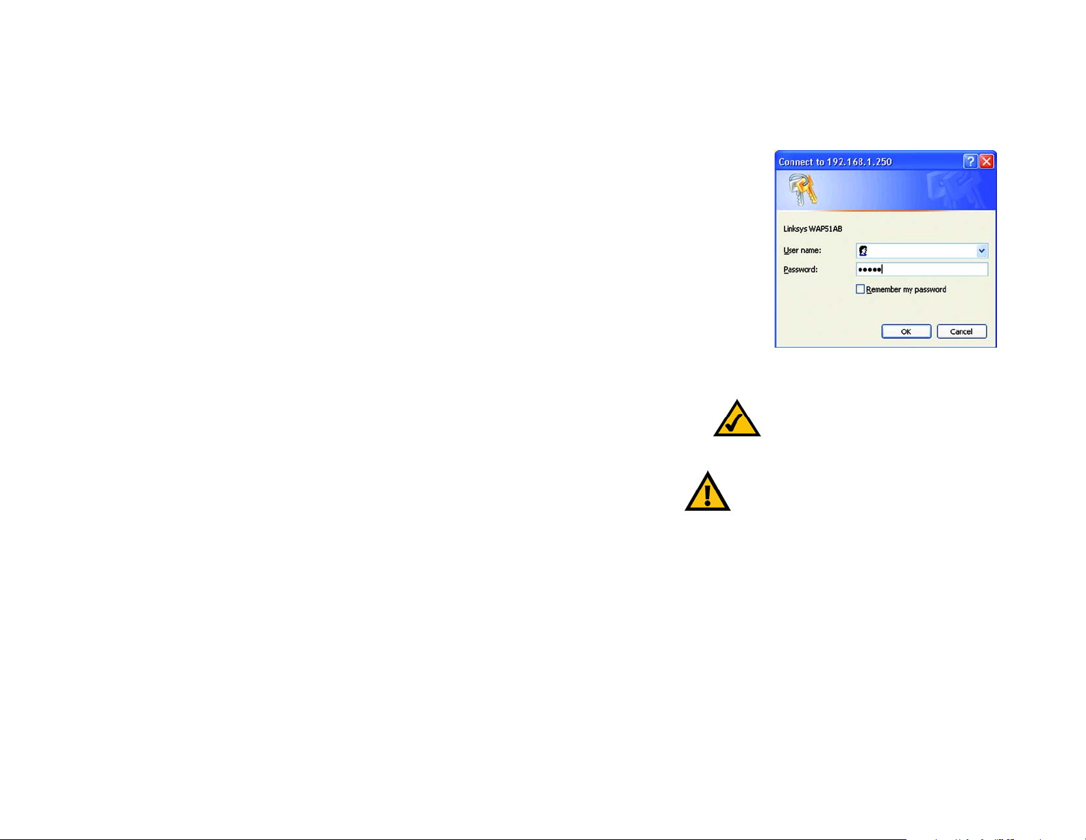
2.An Enter Network Password window, shown in Figure 5-2, will appear. (Windows XP users will see a similar
screen.) Leave the User Name field empty, and enter admin in lowercase letters in the Password field (admin is
the default password). Then, click the OK button.
3.The web-based utility will appear with the Setup tab selected. Select the time zone for your location. If your
location experiences daylight savings, leave the checkmark in the box next to Automatically adjust clock for
daylight saving changes.
Figure 6-1: Password Screen
Note: For added security, you should change
the password through the Security screen of
the web-based utility.
4.Based on the setup instructions from your ISP, you may need to provide the Host Name and Domain Name
(usually cable ISPs require them). These fields allow you to provide a host name and domain name for the Router
and are usually left blank.
The values for the Router’s LAN IP Address and Subnet Mask are shown on the Setup screen. The default values
are 192.168.1.1 for the IP Address and 255.255.255.0 for the Subnet Mask.
5.The Router supports four connection types: Automatic Configuration - DHCP (obtain an IP automatically), Static
IP, PPPoE, and PPTP. These types are listed in the drop-down menu for the Configuration Type setting. Eac h Setup
screen and available features will differ depending on what kind of connection type you select. Proceed to the
instructions for the connection type you are using, and then continue to step 6.
Chapter 6: Configuring the Router’s Basic Settings
IMPORTANT: If you have previously enabled any
Internet-sharing proxy server software on any of your
PCs, you must disable it now. Some examples of
Internet-sharing software are Internet LanBridge,
Wingate, ICS, and Sygate. To disable your Internetsharing software:
• If you are running Netscape Navigator, click Edit,
Preferences, Advanced, and Proxies. Click Direct
Connection to the Internet.
• If you are running Internet Explorer 5.x or higher,
click Tools, Settings, Control Panel, Internet
Options, Connections, and LAN Settings. Remove
checkmarks from all three boxes. Click the OK
button to continue.
You must also disable any Internet log-on software (such
as Ivasion Winpoet or Enternet 300) and any firewall
software (such as ZoneAlarm and Watchdog) on all of
your PCs.
18
Dual-Band Wireless Access Point
The Setup Tab
The Setup Tab
The first screen that appears displays the Setup tab. This allows you to change the Access Point's general
The first screen that appears displays the Setup tab. This allows you to change the Access Point's general
settings. Change these settings as described here and click the Apply button to apply your changes or Cancel to
settings. Change these settings as described here and click the Apply button to apply your changes or Cancel to
cancel your changes. If you require online help, click the Help button.
cancel your changes. If you require online help, click the Help button.
• Firmware. This will display the Access Point's current firmware version. Firmware can be upgraded from the
• Firmware. This will display the Access Point's current firmware version. Firmware can be upgraded from the
Help tab.
Help tab.
• Access Point Name. You may assign any name to the Access Point. Unique, memorable names are helpful,
• Access Point Name. You may assign any name to the Access Point. Unique, memorable names are helpful,
especially if you are employing multiple access points on the same network. Verify this is the name you wish
especially if you are employing multiple access points on the same network. Verify this is the name you wish
to use and click the Apply button to set it.
to use and click the Apply button to set it.
• Static IP Address. This IP address must be unique to your network. (The default IP address is 192.168.1.250.
• Static IP Address. This IP address must be unique to your network. (The default IP address is 192.168.1.250.
As this is a private IP address, there is no need to purchase a separate IP address from your service provider.)
As this is a private IP address, there is no need to purchase a separate IP address from your service provider.)
Verify the address and click the Apply button to save changes.
Verify the address and click the Apply button to save changes.
• Subnet Mask. The Access Point's Subnet Mask must be the same as your Ethernet (wired) network. Verify
• Subnet Mask. The Access Point's Subnet Mask must be the same as your Ethernet (wired) network. Verify
this is correct and click the Apply button to set it.
this is correct and click the Apply button to set it.
5GHz/802.11a Wireless Settings
5GHz/802.11a Wireless Settings
• SSID. The SSID is the unique name shared among all points in a wireless network. The SSID must be identical
• SSID. The SSID is the unique name shared among all points in a wireless network. The SSID must be identical
for all points in the wireless network. It is case sensitive and must not exceed 32 alphanumeric characters,
for all points in the wireless network. It is case sensitive and must not exceed 32 alphanumeric characters,
which may be any keyboard character. Make sure that this setting is the same for all points in your wireless
which may be any keyboard character. Make sure that this setting is the same for all points in your wireless
network.
network.
Figure 6-2: Setup Tab
• Channel. Select the appropriate channel from the list provided to correspond with your network settings. This
• Channel. Select the appropriate channel from the list provided to correspond with your network settings. This
should be between 36 and 64 (in North America). All points in your wireless network must use the same
should be between 36 and 64 (in North America). All points in your wireless network must use the same
channel in order to function correctly.
channel in order to function correctly.
• WEP. The WEP Encryption method is Disabled by default. To enable WEP, click the WEP Key Setting button.
• WEP. The WEP Encryption method is Disabled by default. To enable WEP, click the WEP Key Setting button.
For more information on WEP and wireless security, refer to Appendix B: Wireless Security.
For more information on WEP and wireless security, refer to Appendix B: Wireless Security.
Click the Apply button to apply your changes or Cancel to cancel your changes. If you require online help, click
Click the Apply button to apply your changes or Cancel to cancel your changes. If you require online help, click
the Help button.
the Help button.
Chapter 6: Configuring the Router’s Basic Settings
The Setup Tab
firmware: the programming code that runs a
networking device
static ip address: a fixed address assigned to
a computer or device connected to a network
19
Dual-Band Wireless Access Point
2.4GHz/802.11b Wireless Settings
• SSID. The SSID is the unique name shared among all points in a wireless network. The SSID must be identical
for all points in the wireless network. It is case sensitive and must not exceed 32 alphanumeric characters,
which may be any keyboard character. Make sure this setting is the same for all points in your wireless
network.
• Channel. Select the appropriate channel from the list provided to correspond with your network settings. This
should be between 1 and 11 (in North America). All points in your wireless network must use the same
channel in order to function correctly.
• WEP. The WEP Encryption method is Disabled by default. To enable WEP, click the WEP Key Setting button. For
more information on WEP and wireless security, refer to Appendix B: Wireless Security.
Click the Apply button to apply your changes or Cancel to cancel your changes. If you require online help, click
the Help button.
The Password Tab
The Password tab allows you to change the Access Point's password and restore factory defaults.
Figure 6-3: 802.11b Wireless Settings
Changing the sign-on password for the Access Point is as easy as typing the password into the AP Password
field. Then, type it again into the second field to confirm.
To restore the Access Point's factory default settings, click the Yes button beside Restore Factory Defaults.
Click the Apply button to apply your changes or Cancel to cancel your changes. If you require online help, click
the Help button.
Chapter 6: Configuring the Router’s Basic Settings
The Password Tab
Figure 6-4: Password Tab
20

Dual-Band Wireless Access Point
The Status Tab
The Status tab will display current information on the Access Point, its settings and performance.
• Firmware Version. This displays the current version of the Access Point's firmware. Firmware should only be
upgraded if you experience problems with the Access Point and can be upgraded from the Help tab.
• IP Address. This IP address is the unique address to your network.
• Subnet Mask. This is the Access Point's Subnet Mask, which is the same as that on your Ethernet network.
• SSID. The SSID is the unique name shared among all points in a wireless network.
• Encryption Function. The encryption method you chose in the Setup Wizard or changed from the Setup tab of
this Web-based Utility is displayed here.
• Channel. This is the channel at which your wireless network broadcasts. All points in your wireless network
must use the same channel in order to function correctly.
The Help Tab
For help on the various tabs in this Web-based Utility, along with upgrading the Access Point's firmware and
viewing this Guide, click the Help tab.
The help files for the various tabs in this Web-based Utility are listed by tab name on the left-hand side of the
screen.
Figure 6-5: Status Tab
IMPORTANT: Restoring the Access Point's factory
default settings will erase all of your settings
(WEP Encryption, Wireless and LAN settings, etc.),
and replace them with the factory defaults. Do not
reset the Access Point if you want to retain these
settings.
The following resources require an Internet connection in order to access them.
Click the Linksys Website link to connect to the Linksys homepage for Knowledgebase help files and information
about other Linksys products.
For an Online Manual in PDF format, click that text link. The manual will appear in Adobe pdf format. If you do not
have the Adobe PDF Reader installed on your computer, click the Adobe Website link to download this software.
Firmware can be upgraded by clicking the Upgrade Firmware link. Do not upgrade your firmware unless you are
experiencing problems with the Access Point. For more information about upgrading firmware, refer to Appendix
C: Upgrading Firmware.
Chapter 6: Configuring the Router’s Basic Settings
The Status Tab
Figure 6-6: Help Tab
21

Dual-Band Wireless Access Point
The Filter Tab
The Filter tab allows you to block and allow certain computers, by their MAC Address, from communicating with
the Access Point.
To enable filtering of computers by their MAC Addresses, click the Enable radio button. To disable this feature,
click the radio button by Disable.
T ype the MAC Addresses for those PCs you wish to allow access to the Access Point in the MAC Address fields. As
long as Filtering is enabled, PCs with MAC Addresses not entered in the MAC Address field will not be allowed to
communicate with the Access Point.
When you've completed making any changes on this tab, click the Apply button to save those changes or Cancel
to exit the Web-based Utility without saving changes. To clear any of the information you've typed by not yet
applied, click the Clear button. For more information on this tab, you can click the Help button.
Figure 6-7: Filter Tab
Chapter 6: Configuring the Router’s Basic Settings
The Filter Tab
22

Dual-Band Wireless Access Point
The Wireless Tab
The Wireless Tab
Before making any changes to the Wireless tab, please check your wireless settings on other systems, as these
Before making any changes to the Wireless tab, please check your wireless settings on other systems, as these
changes will alter the effectiveness of the Access Point. In most cases, these settings do not need to be changed.
changes will alter the effectiveness of the Access Point. In most cases, these settings do not need to be changed.
• Beacon Interval. This value indicates the frequency interval of the beacon. A beacon is a packet broadcast by
• Beacon Interval. This value indicates the frequency interval of the beacon. A beacon is a packet broadcast by
the Access Point to keep the network synchronized. A beacon includes the wireless LAN service area, the AP
the Access Point to keep the network synchronized. A beacon includes the wireless LAN service area, the AP
address, the Broadcast destination addresses, a time stamp, Delivery Traffic Indicator Maps, and the Traffic
address, the Broadcast destination addresses, a time stamp, Delivery Traffic Indicator Maps, and the Traffic
Indicator Message (TIM).
Indicator Message (TIM).
• RTS Threshold. This setting determines how large a packet can be before the Access Point coordinates
• RTS Threshold. This setting determines how large a packet can be before the Access Point coordinates
transmission and reception to ensure efficient communication. This value should remain at its default setting
transmission and reception to ensure efficient communication. This value should remain at its default setting
of 2,346. Should you encounter inconsistent data flow, only minor modifications are recommended.
of 2,346. Should you encounter inconsistent data flow, only minor modifications are recommended.
• Fragmentation Length. This specifies the maximum size a data packet will be before splitting and creating a
• Fragmentation Length. This specifies the maximum size a data packet will be before splitting and creating a
new packet and should remain at its default setting of 2,346. A smaller setting means smaller packets, which
new packet and should remain at its default setting of 2,346. A smaller setting means smaller packets, which
will create more packets for each transmission. If you have decreased this value and experience high packet
will create more packets for each transmission. If you have decreased this value and experience high packet
error rates, you can increase it again, but it will likely decrease overall network performance. Only minor
error rates, you can increase it again, but it will likely decrease overall network performance. Only minor
modifications of this value are recommended.
modifications of this value are recommended.
• Data Beacon Rate. (5GHz/802.11a only) This value, between 1 and 16384, indicates the interval of the
• Data Beacon Rate. (5GHz/802.11a only) This value, between 1 and 16384, indicates the interval of the
Delivery Traffic Indication Message. A Data Beacon Rate field is a countdown field informing clients of the
Delivery Traffic Indication Message. A Data Beacon Rate field is a countdown field informing clients of the
next window for listening to broadcast and multicast messages. When the Access Point has buffered
next window for listening to broadcast and multicast messages. When the Access Point has buffered
broadcast or multicast messages for associated clients, it sends the next message with a rate value. Access
broadcast or multicast messages for associated clients, it sends the next message with a rate value. Access
Point Clients hear the beacons and awaken to receive the broadcast and multicast messages.
Point Clients hear the beacons and awaken to receive the broadcast and multicast messages.
Figure 6-8: Wireless Tab
• Turbo Mode. (5GHz/802.11a only) Click the radio button beside Enable to increase the speed of your wireless
• Turbo Mode. (5GHz/802.11a only) Click the radio button beside Enable to increase the speed of your wireless
transmissions to 72 Mbps, keeping in mind that the Access Point's range diminishes in Turbo Mode. If you do
transmissions to 72 Mbps, keeping in mind that the Access Point's range diminishes in Turbo Mode. If you do
not wish to utilize Turbo Mode, make sure the radio button beside Disable is selected.
not wish to utilize Turbo Mode, make sure the radio button beside Disable is selected.
• DTIM Interval. (2.4GHz/802.11b only) This value indicates how often the Access Point sends out a Delivery
• DTIM Interval. (2.4GHz/802.11b only) This value indicates how often the Access Point sends out a Delivery
Traffic Indication Message. Lower settings result in more efficient networking , while preventing your PC from
Traffic Indication Message. Lower settings result in more efficient networking , while preventing your PC from
dropping into power-saving sleep mode. Higher settings allow your PC to enter sleep mode, thus saving
dropping into power-saving sleep mode. Higher settings allow your PC to enter sleep mode, thus saving
power, but interferes with wireless transmissions.
power, but interferes with wireless transmissions.
• Transmission Rates. The basic transfer rates should be set depending on the speed of your wireless network.
You can select from a range of transmission speeds or select Best to have the Access Point automatically
engage the network's optimum speed.
Chapter 6: Configuring the Router’s Basic Settings
The Wireless Tab
23

Dual-Band Wireless Access Point
• Preamble Type. (2.4GHz/802.11b only) The preamble synchronizes network traffic for more efficient
communication. Small networks benefit most from Short preambles. Large networks benefit from Long
preambles. All points in your wireless network must be set to the same preamble type.
• Authentication Type. You may choose between Open System or Shared Key. The Authentication Type default
is set to Open System, in which the sender and the recipient do NOT share a secret key. Each party generates
its own key-pair and asks the receiver to accept the randomly generated key. Once accepted, this key is
used for a short time only. Then a new key is generated and agreed upon. Shared Key is when both the
sender and the recipient share a secret key.
When you've completed making any changes on this tab, click the Apply button to save those changes or Cancel
to exit the Web-based Utility without saving changes. For more information on this tab, you can click the Help
button.
Figure 6-9:
Chapter 6: Configuring the Router’s Basic Settings
The Wireless Tab
Figure 6-10:
Figure 6-11:
Figure 6-12:
Figure 6-13:
Figure 6-14:
Figure 6-15:
24
Dual-Band Wireless Access Point
Chapter 5: Configuring the PCs
Overview
The instructions in this chapter will help you configure each of your computers to be able to communicate with
the Router.
To do this, you need to configure your PC’s network settings to obtain an IP (or TCP/IP) address automatically, so
your PC can function as a DHCP client. Computers use IP addresses to communicate with the Router and each
other across a network, such as the Internet.
First, find out which Windows operating system your computer is running. You can find out by clicking the Start
button. Read the side panel of the Start menu to find out which operating system your PC is running.
You may need to do this for each computer you are connecting to the Router.
The next few pages tell you, step by step, how to configure your network settings based on the type of Windows
operating system you are using. Make sure that an Ethernet or wireless adapter (also known as a network
adapter) has been successfully installed in each PC you will configure. Once you’ve configured your computers,
continue to “Chapter 5: Configure the Router’s Basic Settings.”
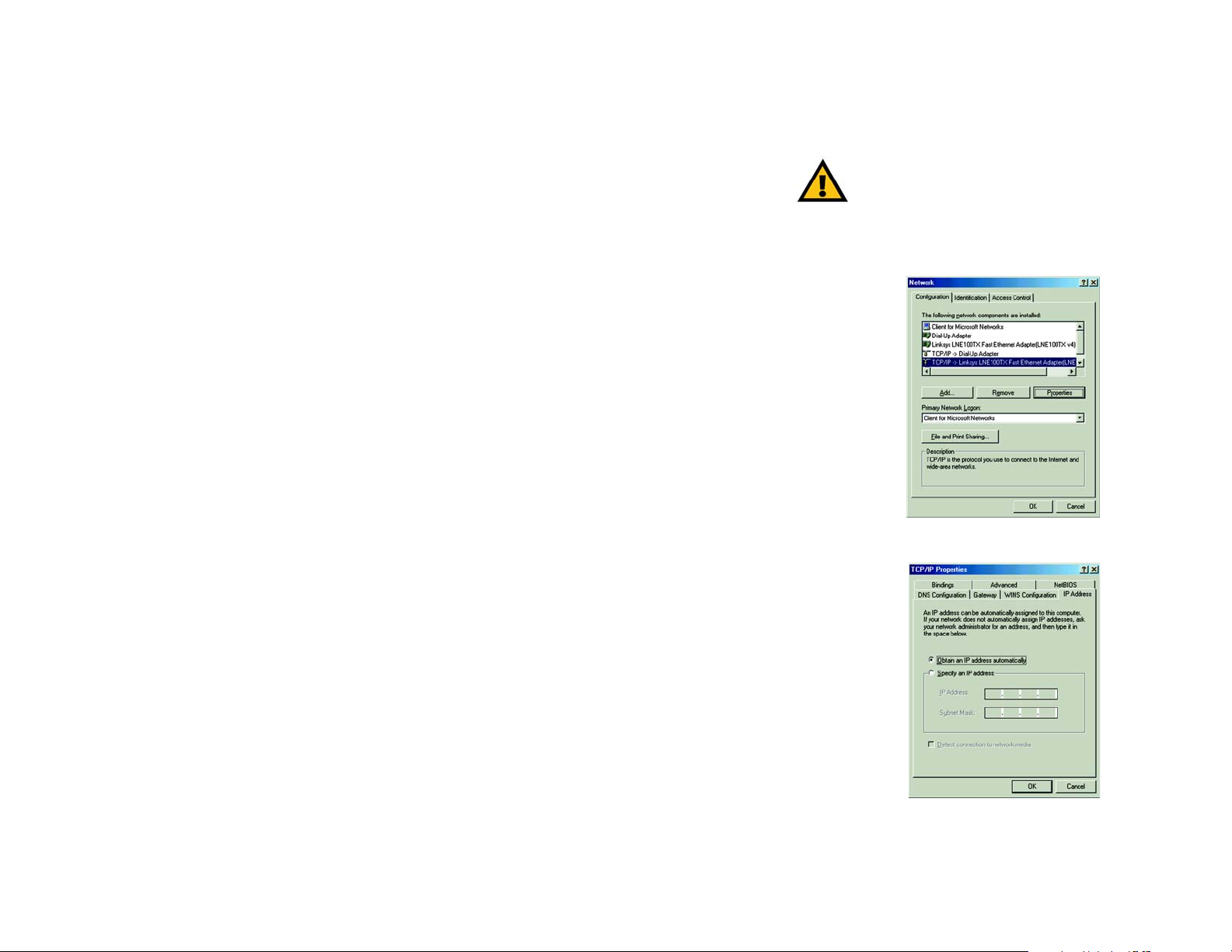
Configuring Windows 98 and Millennium PCs
1. Click the Start button. Select Settings and click the Control Panel icon. Double-click the Network icon.
2. On the Configuration tab, select the TCP/IP line for the applicable Ethernet adapter. Do not choose a TCP/IP
entry whose name mentions DUN, PPPoE, VPN, or AOL. If the word TCP/IP appears by itself, select that line.
Click the Properties button.
IMPORTANT: Important: By default Windows 98,
2000, Me, and XP has TCP/IP installed and set to
obtain an IP address automatically . If your PC does
not have TCP/IP installed, click Start and then
Help. Search for the keyword TCP/IP. Then follow
the instructions to install TCP/IP.
Figure 5-1: Welcome
Chapter 5: Configuring the PCs
Overview
Figure 5-2: Connecting
14

Dual-Band Wireless Access Point
Chapter 4: Connecting the Wireless-G Broadband Router
Overview
The Router’s setup consists of more than simply plugging hardware together. You will have to configure your
networked PCs to accept the IP addresses that the Router assigns them (if applicable), and you will also have to
configure the Router with setting(s) provided by your Internet Service Provider (ISP).
The installation technician from your ISP should have left the setup information for your modem with you after
installing your broadband connection. If not, you can call your ISP to request that data.
Once you have the setup information you need for your specific type of Internet connection, you can begin
installation and setup of the Router.
If you want to use a PC with an Ethernet adapter to configure the Router, go to “Wired Connection to a PC.” If
you want to use a PC with a wireless adapter to configure the Router, go to “Wireless Connection to a PC and
Boot-Up.”
Wired Connection to a PC
1.Before you begin, make sure that all of your network’ s hardwar e is powered off, including the Router, PCs, and
cable or DSL modem.
2.Connect one end of an Ethernet network cable to one of the LAN ports (labeled 1-4) on the back of the Router,
and the other end to an Ethernet port on a PC.
Repeat this step to connect more PCs, a switch, or other network devices to the Router.
3.Connect a different Ethernet network cable from your cable or DSL modem to the Inter net port on the Router’s
rear panel. This is the only port that will work for your modem connection.
4.Power on the cable or DSL modem.
5.Connect the power adapter to the Router’s Power port, and then plug the power adapter into a power outlet.
•The Power LED on the front panel will light up green as soon as the power adapter is connected properly.
•The Diag LED will light up red for a few seconds. It will turn off when the self-test is complete. If this LED stays
on for one minute or longer, see “Appendix A: Troubleshooting.”
Chapter 4: Connecting the Wireless-G Broadband Router
Overview
NOTE: IYou should always plug the Router’s
power adapter into a power strip with surge
protection.
HAVE YOU:r.Have you checked that the Link/
Act LEDs for all your LAN connections and the
Link LED for your Internet connection light up?
If all of your Link LEDs are not lighting up,
make sure that all your cables are securely
plugged in, and that all of your hardware is
powered on properly. Verify that the modem is
plugged into the Internet port on the Router.
11
Dual-Band Wireless Access Point
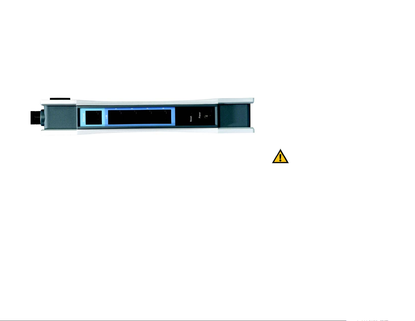
Chapter 3: Getting to Know the Wireless-G Broadband VPN
Router
The Back Panel
The Router’s ports, where a network cable is connected, are located on the back panel.
Figure 3-1: Back Panel
Important: Resetting the Access Point will
Internet The Internet port connects to your modem.
LAN (1-4) The LAN (Local Area Network) ports connect to your PC and other network devices.
Power The Power port is where you will connect the power adapter.
Reset Button There are two ways to Reset the Router's factory defaults. Either press the Reset Button, for
approximately ten seconds, or restore the defaults from the Password tab in the Access
Point's Web-Based Utility.
erase all of your settings (WEP Encryption,
Wireless and LAN settings, etc.) and replace
them with the factory defaults. Do not reset
the Access Point if you want to retain these
settings.
With these, and many other, Linksys products, your networking options are limitless. Go to the Linksys website at
www.linksys.com for more information about products that work with the Access Point.
The Front Panel
The Router's LEDs, where information about network activity is displayed, are located on the front panel.
Chapter 3: Getting to Know the Wireless-G Broadband VPN Router
The Back Panel
8

Dual-Band Wireless Access Point
Chapter 7: Configuring the Router’s Web-Based Utility
Overview
Use the Router’s web-based utility to administer it. This chapter will describe each web page in the Utility and
each page’s key functions. The utility can be accessed via your web browser through use of a computer
connected to the Router. For a basic network setup, most users only have to use the following screens of the
Utility:
• Basic Setup. On the Basic Setup screen, enter the settings provided by your ISP.
• Management. Click the Administration tab and then the Management tab. The Router’s default password is
admin. To secure the Router, change the Password from its default.
There are seven main tabs: Setup, Wireless, Security, Access Restrictions, Applications & Gaming,
Administration, and Status. Additional tabs will be available after you click one of the main tabs.
Setup
• Basic Setup. Enter the Internet connection and network settings on this screen.
• DDNS. To enable the Router’s Dynamic Domain Name System (DDNS) feature, complete the fields on this
screen.
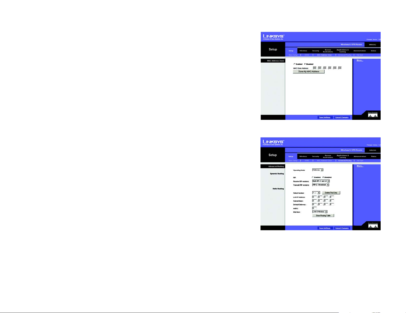
• MAC Address Clone. If you need to clone a MAC address onto the Router, use this screen.
• Advanced Routing. On this screen, you can alter Network Address Translation (NAT), Dynamic Routing, and
Static Routing configurations.
• Hot Spot. Register your Hot Spot service provider on this screen.
Wireless
• Basic Wireless Settings. You can choose your Wireless Network Mode and Wireless Security on this screen.
• Wireless Network Access. This screen displays your network access list.
Chapter 7: Configuring the Router’s Web-Based Utility
Overview
Figure 7-1: Password Screen
Note: For added security, you should change
the password through the Security screen of
the web-based utility.
NAT (Network Address Translation): NAT
technology translates IP addresses of a local area
network to a different IP address for the Internet.
25

Dual-Band Wireless Access Point
• Advanced Wireless Settings. On this screen you can access the Advanced Wireless features of Authentication
Type, Basic Data Rates, Control Tx Rates, Beacon Interval, DTIM Interval, RTS Threshold, and Fragmentation
Threshold.
Security
• Filter. To block specific users from Internet access, you can set up IP address, port, and MAC address filtering
on the Filter screen.
• VPN Passthrough. To enable or disable IPSec, PPPoE, and/or PPTP Pass-through, use this screen.
Access Restrictions
• Access Restriction
Applications & Gaming
• Port Range Forwarding. To set up public services or other specialized Internet applications on your network,
click this tab.
• Port Trigge ring. To set up triggered ranges and forwarded ranges for Internet applications, click this tab.
• UPnP Forwarding. Use this screen to alter UPnP forwarding settings.
• DMZ. To allow one local user to be exposed to the Internet for use of special-purpose services, use this
screen.
Beacon Interval :The frequency interval of the
beacon, which is a packet broadcast by a
router to synchronize a wireless network.
DTIM (Delivery Traffic Indication Message):
A message included in data packets that can
increase wireless efficiency.
RTS (Request To Send): A packet sent when a
computer has data to transmit. The computer
will wait for a CTS (Clear To Send) message
before sending data.
Fragmentation: Breaking a packet into smaller
units when transmitting over a network medium
that cannot support the original size of the
packet.
Administration
• Management. On this screen, alter router access privileges and UPnP settings.
• Log. If you want to view or save activity logs, click this tab.
• Factory Defaults. If you want to restore the Router’s factory defaults, then use this screen.
• Firmware Upgrade. Click this tab if you want to upgrade the Router’s firmware.
Status
• Router. This screen provides status information about the Router.
Chapter 7: Configuring the Router’s Web-Based Utility
Overview
26
Dual-Band Wireless Access Point
• Local Network. This provides status information about the local network.
How to Access the Web-based Utility
T o access the web-based utility, launch Internet Explorer or Netscape Navigator, and enter the Router’ s default IP
address, 192.168.1.1, in the Address field. Then press Enter.
A password request page, shown in Figure 6-2 will pop up. (non-Windows XP users will see a similar screen.)
Leave the User Name field blank, and enter admin (the default password) in the Password field. Then click the
OK button.
T o save your changes on any page, click the Apply button. T o cancel any unsaved changes on any page , click the
Cancel button.
The Setup Tab
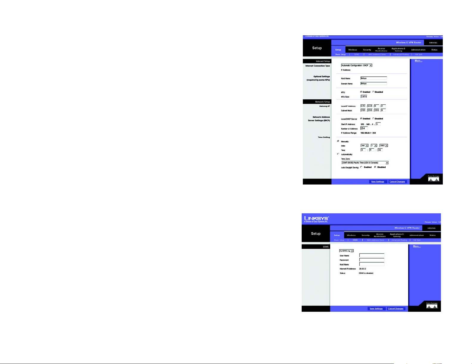
The Basic Setup Tab
The first screen that appears is the Basic Setup tab. This tab allows you to change the Router's general settings.
Change these settings as described here and click the Save Settings button to save your changes or Cancel
Changes to cancel your changes.
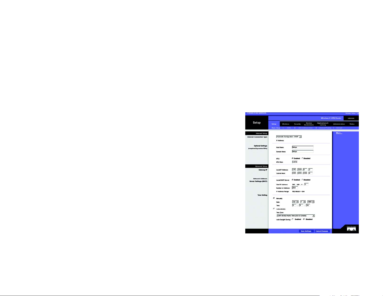
Internet Setup
• Internet Connection Type. The Router supports four connection types: Automatic Configuration - DHCP (the
default connection type), PPPoE, Static IP, and PPTP. Each Basic Setup screen and available features will
differ depending on what kind of connection type you select.
Automatic Configuration - DHCP
By default, the Router’s Configuration Type is set to Automatic Configuration - DHCP, and it should be kept
only if your ISP supports DHCP or you are connecting through a dynamic IP address.
Chapter 7: Configuring the Router’s Web-Based Utility
How to Access the Web-based Utility
Figure 7-2: Setup Tab/DHCP Internet Connection Type
27

Dual-Band Wireless Access Point
Static
If you are required to use a permanent IP address to connect to the Internet, then select Static IP.
• IP Address. This is the Router’s IP address, when seen from the WAN, or the Internet. Your ISP will provide
you with the IP Address you need to specify here.
• Subnet Mask. This is the Router’s Subnet Mask, as seen by external users on the Internet (including your
ISP). Your ISP will provide you with the Subnet Mask.
• Default Gateway. Your ISP will provide you with the Default Gateway Address, which is the ISP server’s IP
address.
• Primary DNS. (Required) and Secondary DNS (Optional). Your ISP will provide you with at least one DNS
(Domain Name System) Server IP Address.
T o save your c hanges on this page, click the Apply button. To cancel any unsaved changes on this page, click
the Cancel button.
PPPOE
Some DSL-based ISPs use PPPoE (Point-to-Point Protocol over Ethernet) to establish Internet connections. If
you are connected to the Internet through a DSL line, check with your ISP to see if they use PPPoE. If they do,
you will have to enable PPPoE.
• User Name and Password. Enter the User Name and Password provided by your ISP.
• Connect on Demand: Max Idle Time. You can configure the Router to cut the Internet connection after it
has been inactive for a specified period of time (Max Idle Time). If your Internet connection has been
terminated due to inactivity, Connect on Demand enables the Router to automatically re-establish your
connection as soon as you attempt to access the Internet again. If you wish to activate Connect on
Demand, click the radio button. In the Max Idle Time field, enter the number of minutes you want to have
elapsed before your Internet connection terminates.
• Keep Alive Option: Redial Period. If you select this option, the Router will periodically check your Internet
connection. If you are disconnected, then the Router will automatically re-establish your connection. To
use this option, click the radio button next to Keep Alive. In the Redial Period field, you specify how often
you want the Router to check the Internet connection. The default Redial Period is 30 seconds.
T o save your c hanges on this page, click the Apply button. To cancel any unsaved changes on this page, click
the Cancel button. To get more information about the features, click the Help button.
Chapter 7: Configuring the Router’s Web-Based Utility
The Setup Tab
Figure 7-3: Static Internet Connection Type
Figure 7-4: PPPoE Internet Connection Type
28
Dual-Band Wireless Access Point
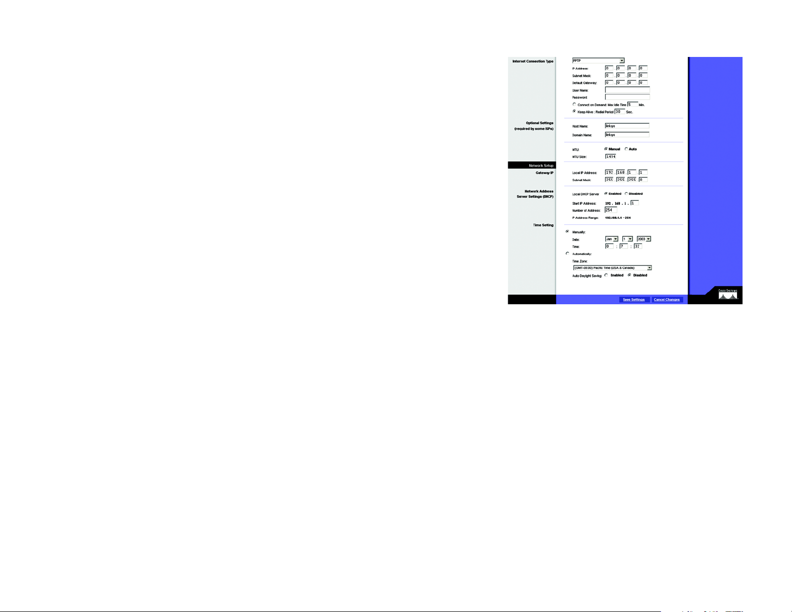
PPPTP
Point to Point Tunneling Protocol (PPTP) is a service that applies to connections in Europe only (see Figure 6-
8).
• Internet IP Address. This is the Router’s IP address, when seen from the Internet. Your ISP will provide you
with the IP Address you need to specify here.
• Subnet Mask. This is the Router’s Subnet Mask, as seen by external users on the Internet (including your
ISP). Your ISP will provide you with the Subnet Mask.
• Default Gateway. Your ISP will provide you with the Default Gateway Address.
• User Name and Passwor. Enter the User Name and Password provided by your ISP.
• Connect on Demand: Max Idle Time. You can configure the Router to cut the Internet connection after it
has been inactive for a specified period of time (Max Idle Time). If your Internet connection has been
terminated due to inactivity, Connect on Demand enables the Router to automatically re-establish your
connection as soon as you attempt to access the Internet again. If you wish to activate Connect on
Demand, click the radio button. In the Max Idle Time field, enter the number of minutes you want to have
elapsed before your Internet connection terminates.
• Keep Alive Option: Redial Period. If you select this option, the Router will periodically check your Internet
connection. If you are disconnected, then the Router will automatically re-establish your connection. To
use this option, click the radio button next to Keep Alive. To use this option, click the radio button next to
Keep Alive. In the Redial Period field, you specify how often you want the Router to check the Internet
connection. The default Redial Period is 30 seconds.
T o save your changes on this page, click the Apply button. To cancel any unsaved changes on this page, clic k
the Cancel button. To get more information about the features, click the Help button.
Optional Settings (Required by some ISPs)
• Host Name and Domain Name. These fields allow you to supply a host and domain name for the Router. Some
ISPs require these names as identification. You may have to check with your ISP to see if your broadband
Internet service has been configured with a host and domain name. In most cases, leaving these fields blank
will work.
• MTU. The MTU (Maximum Transmission Unit) setting specifies the largest packet size permitted for network
transmission. Select Enabled and enter the value desired. It is recommended that you leave this value in the
Chapter 7: Configuring the Router’s Web-Based Utility
The Setup Tab
Figure 7-5: PPTP Internet Connection Type
29
 Loading...