

Page 1
Wireless-G VPN Router
with RangeBooster
USER GUIDE
BUSINESS SERIES
v
Model: WRV200
Page 2

About This Guide
About This Guide
Icon Descriptions
While reading through the User Guide you may see
various icons that call attention to specific items. Below is
a description of these icons:
NOTE: This check mark indicates that there is
a note of interest and is something that you
should pay special attention to while using the
product.
WARNING: This exclamation point indicates
that there is a caution or warning and it is
something that could damage your property or
product.
WEB: This globe icon indicates a noteworthy
website address or e-mail address.
Open Source
This product may contain material licensed to you under
the GNU General Public License or other open-source
software licenses. Upon request, open-source software
source code is available at cost from Linksys for at least
three years from the product purchase date.
WEB: For detailed license terms and additional
information visit: www.linksys.com/gpl
Online Resources
Website addresses in this document are listed without
http:// in front of the address because most current web
browsers do not require it. If you use an older web browser,
you may have to add http:// in front of the web address.
Resource Website
Linksys www.linksys.com
Linksys International www.linksys.com/international
Glossary www.linksys.com/glossary
Network Security www.linksys.com/security
Copyright and Trademarks
Linksys is a registered trademark or
trademark of Cisco Systems, Inc. and/
or its affiliates in the U.S. and certain
other countries. Copyright © 2007
Cisco Systems, Inc. All rights reserved.
Other brands and product names are
trademarks or registered trademarks
of their respective holders.
Wireless-G VPN Router with RangeBooster
ii
Page 3

Table of Contents
Chapter 1: Introduction 1
Chapter 2: Planning Your Wireless Network
Network Topology . . . . . . . . . . . . . . . . . . . . . . . . . . . . . . . . . . . . . . . . . . . . . 2
Ad-Hoc versus Infrastructure Mode . . . . . . . . . . . . . . . . . . . . . . . . . . . . . . . . . . 2
Network Layout. . . . . . . . . . . . . . . . . . . . . . . . . . . . . . . . . . . . . . . . . . . . . . . 2
Chapter 3: Planning Your Virtual Private Network (VPN) 3
Why do I need a VPN?. . . . . . . . . . . . . . . . . . . . . . . . . . . . . . . . . . . . . . . . . . . 3
1) MAC Address Spoong . . . . . . . . . . . . . . . . . . . . . . . . . . . . . . . . . . . . . 3
2) Data Sning . . . . . . . . . . . . . . . . . . . . . . . . . . . . . . . . . . . . . . . . . . . . 3
3) Man in the middle attacks. . . . . . . . . . . . . . . . . . . . . . . . . . . . . . . . . . . . 3
What is a VPN? . . . . . . . . . . . . . . . . . . . . . . . . . . . . . . . . . . . . . . . . . . . . . . . 3
VPN Router to VPN Router . . . . . . . . . . . . . . . . . . . . . . . . . . . . . . . . . . . . . 4
Computer (using the Linksys VPN client software) to VPN Router . . . . . . . . . . . . 4
Chapter 4: Product Overview 5
Front Panel. . . . . . . . . . . . . . . . . . . . . . . . . . . . . . . . . . . . . . . . . . . . . . . . . . 5
Back Panel . . . . . . . . . . . . . . . . . . . . . . . . . . . . . . . . . . . . . . . . . . . . . . . . . . 5
Chapter 5: Conguring the Wireless-G VPN Router 6
Overview . . . . . . . . . . . . . . . . . . . . . . . . . . . . . . . . . . . . . . . . . . . . . . . . . . . 6
How to Access the Web-based Utility . . . . . . . . . . . . . . . . . . . . . . . . . . . . . . . . . 7
Setup . . . . . . . . . . . . . . . . . . . . . . . . . . . . . . . . . . . . . . . . . . . . . . . . . . . . . 7
Setup > Basic Settings. . . . . . . . . . . . . . . . . . . . . . . . . . . . . . . . . . . . . . . . 7
Setup > VLAN . . . . . . . . . . . . . . . . . . . . . . . . . . . . . . . . . . . . . . . . . . . . .10
Setup > DDNS. . . . . . . . . . . . . . . . . . . . . . . . . . . . . . . . . . . . . . . . . . . . .10
Setup > MAC Address Clone. . . . . . . . . . . . . . . . . . . . . . . . . . . . . . . . . . . .11
Setup > Advanced Routing . . . . . . . . . . . . . . . . . . . . . . . . . . . . . . . . . . . .12
Wireless. . . . . . . . . . . . . . . . . . . . . . . . . . . . . . . . . . . . . . . . . . . . . . . . . . . .13
Wireless > Basic Wireless Settings . . . . . . . . . . . . . . . . . . . . . . . . . . . . . . . .13
Wireless > Wireless Security . . . . . . . . . . . . . . . . . . . . . . . . . . . . . . . . . . . .13
Wireless > Wireless Network Access . . . . . . . . . . . . . . . . . . . . . . . . . . . . . . .16
Wireless > Advanced Wireless Settings . . . . . . . . . . . . . . . . . . . . . . . . . . . . .17
Wireless > WDS . . . . . . . . . . . . . . . . . . . . . . . . . . . . . . . . . . . . . . . . . . . .17
Firewall . . . . . . . . . . . . . . . . . . . . . . . . . . . . . . . . . . . . . . . . . . . . . . . . . . . .18
Firewall > General . . . . . . . . . . . . . . . . . . . . . . . . . . . . . . . . . . . . . . . . . .18
Firewall > Port Forwarding . . . . . . . . . . . . . . . . . . . . . . . . . . . . . . . . . . . . .18
Firewall > Port Triggering. . . . . . . . . . . . . . . . . . . . . . . . . . . . . . . . . . . . . .19
Firewall > DMZ . . . . . . . . . . . . . . . . . . . . . . . . . . . . . . . . . . . . . . . . . . . .19
Firewall > Access Restriction. . . . . . . . . . . . . . . . . . . . . . . . . . . . . . . . . . . .20
Firewall > URL Filtering . . . . . . . . . . . . . . . . . . . . . . . . . . . . . . . . . . . . . . .20
VPN . . . . . . . . . . . . . . . . . . . . . . . . . . . . . . . . . . . . . . . . . . . . . . . . . . . . . .20
VPN > VPN Client Access . . . . . . . . . . . . . . . . . . . . . . . . . . . . . . . . . . . . . .20
2
Wireless-G VPN Router with RangeBooster
i
Page 4

Table of Contents
VPN > VPN Passthrough . . . . . . . . . . . . . . . . . . . . . . . . . . . . . . . . . . . . . .21
VPN > IPSec VPN . . . . . . . . . . . . . . . . . . . . . . . . . . . . . . . . . . . . . . . . . . .22
VPN > VPN Summary . . . . . . . . . . . . . . . . . . . . . . . . . . . . . . . . . . . . . . . .24
QoS . . . . . . . . . . . . . . . . . . . . . . . . . . . . . . . . . . . . . . . . . . . . . . . . . . . . . .25
QoS > Application-Based QoS. . . . . . . . . . . . . . . . . . . . . . . . . . . . . . . . . . .25
QoS > Port-Based QoS. . . . . . . . . . . . . . . . . . . . . . . . . . . . . . . . . . . . . . . .25
Administration . . . . . . . . . . . . . . . . . . . . . . . . . . . . . . . . . . . . . . . . . . . . . . .26
Administration > Management . . . . . . . . . . . . . . . . . . . . . . . . . . . . . . . . . .26
Administration > Log . . . . . . . . . . . . . . . . . . . . . . . . . . . . . . . . . . . . . . . .27
Administration > Diagnostics. . . . . . . . . . . . . . . . . . . . . . . . . . . . . . . . . . .28
Administration > Factory Default. . . . . . . . . . . . . . . . . . . . . . . . . . . . . . . . .28
Administration > Firmware Upgrade . . . . . . . . . . . . . . . . . . . . . . . . . . . . . .28
Administration > Reboot . . . . . . . . . . . . . . . . . . . . . . . . . . . . . . . . . . . . . .29
Status . . . . . . . . . . . . . . . . . . . . . . . . . . . . . . . . . . . . . . . . . . . . . . . . . . . . .29
Status > Router . . . . . . . . . . . . . . . . . . . . . . . . . . . . . . . . . . . . . . . . . . . .29
Status > Local Network . . . . . . . . . . . . . . . . . . . . . . . . . . . . . . . . . . . . . . .30
Status > Wireless . . . . . . . . . . . . . . . . . . . . . . . . . . . . . . . . . . . . . . . . . . .30
Status > System Performance . . . . . . . . . . . . . . . . . . . . . . . . . . . . . . . . . . .30
Status > VPN Clients . . . . . . . . . . . . . . . . . . . . . . . . . . . . . . . . . . . . . . . . .31
Appendix A: Troubleshooting 32
Frequently Asked Questions. . . . . . . . . . . . . . . . . . . . . . . . . . . . . . . . . . . . . . .37
Appendix B: Wireless Security Checklist 39
General Network Security Guidelines . . . . . . . . . . . . . . . . . . . . . . . . . . . . . . . . .39
Additional Security Tips . . . . . . . . . . . . . . . . . . . . . . . . . . . . . . . . . . . . . . . . .39
Appendix C:
Overview . . . . . . . . . . . . . . . . . . . . . . . . . . . . . . . . . . . . . . . . . . . . . . . . . . .40
Before You Begin . . . . . . . . . . . . . . . . . . . . . . . . . . . . . . . . . . . . . . . . . . . . . .40
Installing the Linksys QuickVPN Software . . . . . . . . . . . . . . . . . . . . . . . . . . . . . .40
Using the Linksys QuickVPN Software . . . . . . . . . . . . . . . . . . . . . . . . . . . . . . . .41
Distributing Certicates to QuickVPN Users . . . . . . . . . . . . . . . . . . . . . . . . . . . . .42
Appendix D: Conguring
Introduction. . . . . . . . . . . . . . . . . . . . . . . . . . . . . . . . . . . . . . . . . . . . . . . . .43
Environment . . . . . . . . . . . . . . . . . . . . . . . . . . . . . . . . . . . . . . . . . . . . . . . .43
How to Establish a Secure IPSec Tunnel . . . . . . . . . . . . . . . . . . . . . . . . . . . . . . .43
Using Linksys QuickVPN for Windows 2000, XP, or Vista 40
Installing from the CD-ROM . . . . . . . . . . . . . . . . . . . . . . . . . . . . . . . . . . . .40
Downloading and Installing from the Internet . . . . . . . . . . . . . . . . . . . . . . . .40
Version Number of the QuickVPN Client . . . . . . . . . . . . . . . . . . . . . . . . . . . .41
IPSec with a Windows 2000 or XP Computer 43
Step 1: Create an IPSec Policy . . . . . . . . . . . . . . . . . . . . . . . . . . . . . . . . . . .43
Step 2: Build Filter Lists . . . . . . . . . . . . . . . . . . . . . . . . . . . . . . . . . . . . . . .43
Step 3: Congure Individual Tunnel Rules . . . . . . . . . . . . . . . . . . . . . . . . . . .45
Wireless-G VPN Router with RangeBooster
ii
Page 5

Table of Contents
Step 4: Assign New IPSec Policy. . . . . . . . . . . . . . . . . . . . . . . . . . . . . . . . . .48
Step 5: Create a Tunnel Through the Web-Based Utility . . . . . . . . . . . . . . . . . . .48
Appendix E: Gateway-to-Gateway VPN Tunnel 49
Overview . . . . . . . . . . . . . . . . . . . . . . . . . . . . . . . . . . . . . . . . . . . . . . . . . . .49
Before You Begin . . . . . . . . . . . . . . . . . . . . . . . . . . . . . . . . . . . . . . . . . . . . . .49
Conguration when the Remote Gateway Uses a Static IP Address . . . . . . . . . . . . . .49
Conguration of the WRV200 . . . . . . . . . . . . . . . . . . . . . . . . . . . . . . . . . . .49
Conguration of the RV082 . . . . . . . . . . . . . . . . . . . . . . . . . . . . . . . . . . . .50
Conguration of PC 1 and PC 2 . . . . . . . . . . . . . . . . . . . . . . . . . . . . . . . . . .50
Conguration when the Remote Gateway Uses a Dynamic IP Address. . . . . . . . . . . .51
Conguration of the WRV200 . . . . . . . . . . . . . . . . . . . . . . . . . . . . . . . . . . .51
Conguration of the RV082 . . . . . . . . . . . . . . . . . . . . . . . . . . . . . . . . . . . .51
Conguration of PC 1 and PC 2 . . . . . . . . . . . . . . . . . . . . . . . . . . . . . . . . . .52
Conguration when Both Gateways Use Dynamic IP Addresses . . . . . . . . . . . . . . . .52
Conguration of the WRV200 . . . . . . . . . . . . . . . . . . . . . . . . . . . . . . . . . . .52
Conguration of the RV082 . . . . . . . . . . . . . . . . . . . . . . . . . . . . . . . . . . . .53
Conguration of PC 1 and PC 2 . . . . . . . . . . . . . . . . . . . . . . . . . . . . . . . . . .53
Appendix F: Glossary 54
Appendix G: Specications 5
Appendix H: Warranty Information 5
Exclusions and Limitations. . . . . . . . . . . . . . . . . . . . . . . . . . . . . . . . . . . . . . . .59
Obtaining Warranty Service . . . . . . . . . . . . . . . . . . . . . . . . . . . . . . . . . . . . . . .59
Technical Support . . . . . . . . . . . . . . . . . . . . . . . . . . . . . . . . . . . . . . . . . . . . .60
Appendix I: Regulatory Information 61
FCC Statement . . . . . . . . . . . . . . . . . . . . . . . . . . . . . . . . . . . . . . . . . . . . . . .61
FCC Radiation Exposure Statement . . . . . . . . . . . . . . . . . . . . . . . . . . . . . . . . . .61
Safety Notices. . . . . . . . . . . . . . . . . . . . . . . . . . . . . . . . . . . . . . . . . . . . . . . .61
Industry Canada Statement . . . . . . . . . . . . . . . . . . . . . . . . . . . . . . . . . . . . . . .61
Industry Canada Radiation Exposure Statement: . . . . . . . . . . . . . . . . . . . . . . .61
Avis d’Industrie Canada. . . . . . . . . . . . . . . . . . . . . . . . . . . . . . . . . . . . . . . . . .62
Avis d’Industrie Canada concernant l’exposition aux radiofréquences :. . . . . . . . .62
Wireless Disclaimer . . . . . . . . . . . . . . . . . . . . . . . . . . . . . . . . . . . . . . . . . . . .62
Avis de non-responsabilité concernant les appareils sans l . . . . . . . . . . . . . . . . . .62
User Information for Consumer Products Covered by EU Directive 2002/96/EC on Waste
Electric and Electronic Equipment (WEEE) . . . . . . . . . . . . . . . . . . . . . . . . . . . . . .63
7
9
Appendix J: Contact Information 67
Wireless-G VPN Router with RangeBooster
iii
Page 6

Chapter 1
Chapter 1: Introduction
Thank you for choosing the Wireless-G VPN Router
with RangeBooster. The WRV200 is a VPN router with a
Wireless-G access point for small offices and home offices.
The 10/100 Ethernet WAN interface connects directly
to your broadband DSL or Cable modem. For the LAN
interface, there is a built-in 4-port, full-duplex 10/100
Ethernet switch that can connect up to four devices.
The wireless AP supports 802.11b/g and incorporates
Linksys RangeBooster technology, which utilizes a MIMO
antennae configuration to provide increased coverage
and reliability over standard 802.11g.
The WRV200 has the advanced security functions needed
for business networking. It has a SPI based firewall with
DoS prevention, but also a Virtual Private Networking
(VPN) engine for secure communication between mobile
or remote workers and branch offices. For your wired and
wireless local area network, there is support for multiple
SSIDs and VLANs for traffic separation. The WRV200’s
Wireless AP implements WPA2-PSK, WPA2-ENT, and WEP
encryption, along with other security features including
enabling/disabling SSID Broadcasts and MAC-based
filtering.
Introduction
Wireless networking in business environments requires
additional flexibility. The WRV200 has the capability to
expand or reduce the area of your wireless network.
There is support for Wireless Distribution System (WDS),
which allows the wireless coverage to be expanded
without wires through wireless bridging between it and
select Linksys stand alone access points. That, along with
the ability to increase or decrease the RF output power,
allows for optimal wireless coverage.
To support VoIP, the WRV200 has a SIP application layer
gateway (ALG) and advanced QoS functionality. SIP based
VoIP data has problems traversing through standard
firewalls with NAT, especially when you deploy multiple SIP
clients. The SIP ALG allows SIP traffic from multiple clients
to pass through the router’s firewall. QoS functionality
can improve the quality of your voice or video over IP.
With support for Wireless QoS (WMM) and wired QoS
(port prioritization), consistent voice and video quality is
maintained throughout your business.
Wireless-G VPN Router with RangeBooster
1
Page 7
Chapter 2
Networking and Security Basics
Chapter 2: Planning Your Wireless Network
Network Topology
A wireless local area network (WLAN) is exactly like a regular
local area network (LAN), except that each computer in the
WLAN uses a wireless device to connect to the network.
Computers in a WLAN share the same frequency channel
and SSID, which is an identification name shared by the
wireless devices belonging to the same wireless network.
Ad-Hoc versus Infrastructure Mode
Unlike wired networks, wireless networks have two
different modes in which they may be set up: infrastructure
and ad-hoc. An infrastructure configuration is a WLAN
and wired LAN communicating to each other through
an access point. An ad-hoc configuration is wirelessequipped computers communicating directly with each
other. Choosing between these two modes depends on
whether or not the wireless network needs to share data
or peripherals with a wired network or not.
Network Layout
The Wireless-G VPN Router has been specifically designed
for use with both your 802.11b and 802.11g products.
Now, products using these standards can communicate
with each other.
The Wireless-G VPN Router is compatible with all 802.11g
and 802.11n adapters, such as the Notebook Adapters
(WPC4400N, WPC200) for your laptop computers, PCI
Adapter (WMP200) for your desktop PC, and USB Adapter
(WUSB200, USB1000) when you want to enjoy USB
connectivity. The Router will also communicate with
Wireless Ethernet Bridges (WET200).
When you wish to connect your wireless network with
your wired network, you can use the Router’s four LAN
ports. To add more ports, any of the Router’s LAN ports
can be connected to any Linksys Business Series switch
(such as the SLM series or SRW series switches).
With these, and many other, Linksys products, your
networking options are limitless. Go to the Linksys
website at www.linksys.com for more information about
products that work with the Wireless-G VPN Router with
RangeBooster.
If the computers on the wireless network need to be
accessible by a wired network or need to share a peripheral,
such as a printer, with the wired network computers, the
wireless network should be set up in Infrastructure mode.
The basis of Infrastructure mode centers around an access
point or wireless router, such as the Wireless-G VPN Router,
which serves as the main point of communications in
a wireless network. The Router transmits data to PCs
equipped with wireless network adapters, which can
roam within a certain radial range of the Router. You can
arrange the Router and multiple access points to work
in succession to extend the roaming range, and you can
set up your wireless network to communicate with your
Ethernet hardware as well.
If the wireless network is relatively small and needs to
share resources only with the other computers on the
wireless network, then the Ad-Hoc mode can be used.
Ad-Hoc mode allows computers equipped with wireless
transmitters and receivers to communicate directly with
each other, eliminating the need for a wireless router or
access point. The drawback of this mode is that in AdHoc mode, wireless-equipped computers are not able to
communicate with computers on a wired network. And, of
course, communication between the wireless-equipped
computers is limited by the distance and interference
directly between them.
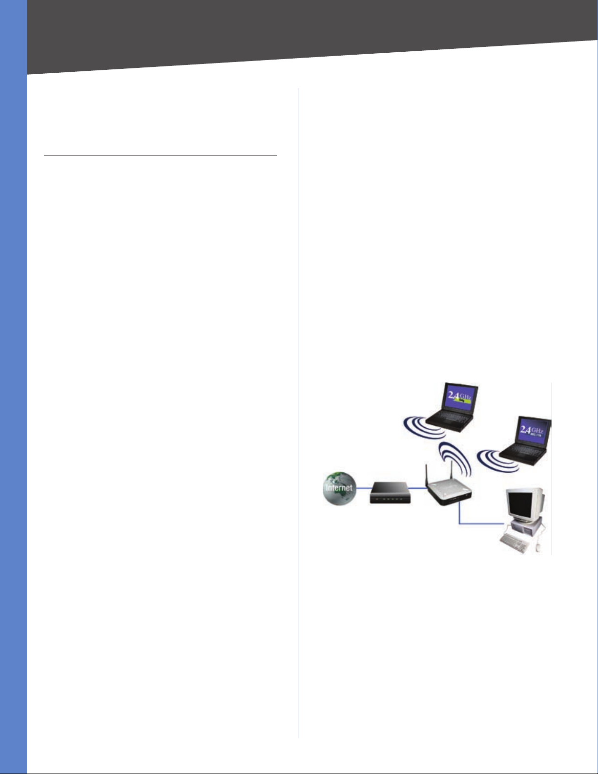
Network Diagram
Wireless-G VPN Router with RangeBooster
2
Page 8

Chapter 3
Planning Your Virtual Private Network (VPN)
Chapter 3: Planning Your Virtual Private Network (VPN)
Why do I need a VPN?
Computer networking provides a flexibility not available
when using an archaic, paper-based system. With this
flexibility, however, comes an increased risk in security.
This is why firewalls were first introduced. Firewalls help
to protect data inside of a local network. But what do you
do once information is sent outside of your local network,
when e-mails are sent to their destination, or when you
have to connect to your company’s network when you are
out on the road? How is your data protected?
That is when a VPN can help. VPNs are called Virtual Private
Networks because they secure data moving outside of
your network as if it were still within that network.
When data is sent out across the Internet from your
computer, it is always open to attacks. You may already
have a firewall, which will help protect data moving
around or held within your network from being corrupted
or intercepted by entities outside of your network, but
once data moves outside of your network—when you
send data to someone via e-mail or communicate with an
individual over the Internet—the firewall will no longer
protect that data.
At this point, your data becomes open to hackers using
a variety of methods to steal not only the data you are
transmitting but also your network login and security
data. Some of the most common methods are as follows:
1) MAC Address Spoofing
Packets transmitted over a network, either your local
network or the Internet, are preceded by a packet
header. These packet headers contain both the source
and destination information for that packet to transmit
efficiently. A hacker can use this information to spoof
(or fake) a MAC address allowed on the network. With
this spoofed MAC address, the hacker can also intercept
information meant for another user.
2) Data Sniffing
3) Man in the middle attacks
Once the hacker has either sniffed or spoofed enough
information, he can now perform a “man in the middle”
attack. This attack is performed, when data is being
transmitted from one network to another, by rerouting
the data to a new destination. Even though the data is not
received by its intended recipient, it appears that way to
the person sending the data.
These are only a few of the methods hackers use and they
are always developing more. Without the security of your
VPN, your data is constantly open to such attacks as it
travels over the Internet. Data travelling over the Internet
will often pass through many different servers around
the world before reaching its final destination. That is a
long way to go for unsecured data and this is when a VPN
serves its purpose.
What is a VPN?
A VPN, or Virtual Private Network, is a connection between
two endpoints—a VPN Router, for instance—in different
networks that allows private data to be sent securely
over a shared or public network, such as the Internet. This
establishes a private network that can send data securely
between these two locations or networks.
This is done by creating a “tunnel”. A VPN tunnel connects
the two PCs or networks and allows data to be transmitted
over the Internet as if it were still within those networks.
Not a literal tunnel, it is a connection secured by encrypting
the data sent between the two networks.
VPN was created as a cost-effective alternative to using
a private, dedicated, leased line for a private network.
Using industry standard encryption and authentication
techniques—IPSec, short for IP Security—VPN creates a
secure connection that, in effect, operates as if you were
directly connected to your local network. VPN can be used
to create secure networks linking a central office with
branch offices, telecommuters, and/or professionals on
the road (travelers can connect to a VPN Router using any
computer with the Linksys VPN client software.)
There are two basic ways to create a VPN connection:
VPN Router to VPN Router
•
Computer (using the Linksys VPN client software) to
•
VPN Router
Data “sniffing” is a method used by hackers to obtain
network data as it travels through unsecured networks,
such as the Internet. Tools for just this kind of activity,
such as protocol analyzers and network diagnostic tools,
are often built into operating systems and allow the data
to be viewed in clear text.
Wireless-G VPN Router with RangeBooster
IMPORTANT: You must have at least one VPN
Router on one end of the VPN tunnel. At the
other end of the VPN tunnel, you must have
a second VPN Router or a computer with the
Linksys VPN client software.
3
Page 9
Chapter 3
The VPN Router creates a “tunnel” or channel between two
endpoints, so that data transmissions between them are
secure. A computer with the Linksys VPN client software
can be one of the two endpoints (refer to “Appendix B:
Using Linksys QuickVPN for Windows 2000, XP, or Vista”).
If you choose not to run the VPN client software, any
computer with the built-in IPSec Security Manager
(Microsoft 2000 and XP) allows the VPN Router to create a
VPN tunnel using IPSec (refer to “Appendix C: Configuring
IPSec between a Windows 2000 or XP PC and the Router”).
Other versions of Microsoft operating systems require
additional, third-party VPN client software applications
that support IPSec to be installed.
VPN Router to VPN Router
An example of a VPN Router-to-VPN Router VPN would
be as follows. At home, a telecommuter uses his VPN
Router for his always-on Internet connection. His router
is configured with his office’s VPN settings. When he
connects to his office’s router, the two routers create a VPN
tunnel, encrypting and decrypting data. As VPNs utilize
the Internet, distance is not a factor. Using the VPN, the
telecommuter now has a secure connection to the central
office’s network, as if he were physically connected. For
more information, refer to “Appendix D: Configuring a
Gateway-to-Gateway IPSec Tunnel.”
Planning Your Virtual Private Network (VPN)
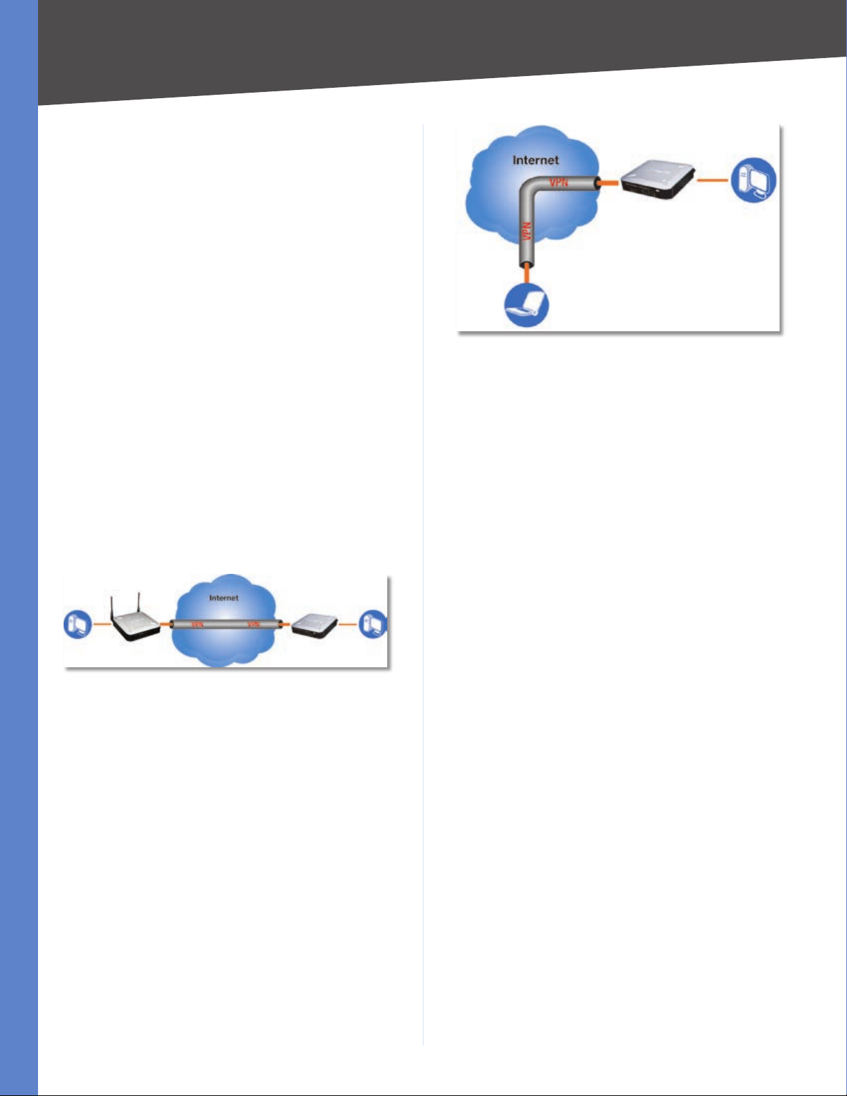
Office
VPN Router PC 2
Off-Site
Laptop running
Linksys VPN Client Software
Computer to VPN Router
For additional information and instructions about
creating your own VPN, please visit Linksys’s website
at www.linksys.com. You can also refer to “Appendix B:
Using Linksys QuickVPN for Windows 2000, XP, or Vista”,
“Appendix C: Configuring IPSec between a Windows 2000
or XP PC and the Router,” and “Appendix D: Configuring a
Gateway-to-Gateway IPSec Tunnel.”
Home Office
PC 1 WRV200 VPN Router PC 2
VPN Router to VPN Router
Computer (using the Linksys VPN client software) to VPN Router
The following is an example of a computer-to-VPN Router
VPN. In her hotel room, a traveling businesswoman dials
up her ISP. Her notebook computer has the Linksys VPN
client software, which is configured with her office’s IP
address. She accesses the Linksys VPN client software and
connects to the VPN Router at the central office. As VPNs
utilize the Internet, distance is not a factor. Using the VPN,
she now has a secure connection to the central office’s
network, as if she were physically connected.
Wireless-G VPN Router with RangeBooster
4
Page 10
Chapter 4
Product Overview
Chapter 4: Product Overview
Front Panel
The Router’s LEDs are located on the front panel of the
Router.
Front Panel
POWER (Green) The Power LED lights up when
the Router is powered on.
DMZ (Green) The DMZ LED lights up when the
Router has an available DMZ port. If the LED is
flashing, the Router is sending or receiving data
over the DMZ port.
INTERNET (Green) The Internet LED lights up
when the Router is connected to your cable or
DSL modem. If the LED is flashing, the Router
is sending or receiving data over the Internet
port.
WIRELESS (Green) The Wireless LED lights
up whenever there is a successful wireless
connection. If the LED is flashing, the Router
is actively sending or receiving data over the
wireless network.
1-4 (ETHERNET) (Green) These four LEDs
correspond to the Router’s four Ethernet
ports. If the LED is continuously lit, the
Router is connected to a device through the
corresponding port (1, 2, 3, or 4). If the LED
is flashing, the Router is actively sending or
receiving data over that port.
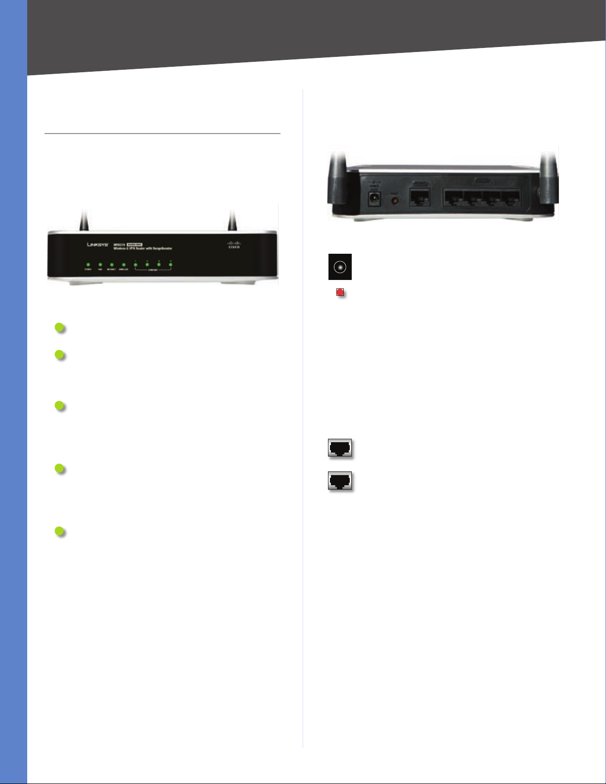
Back Panel
The Router’s ports and Reset button are located on the
back panel of the Router.
Back Panel
POWER The Power port is where you will
connect the AC power cable.
RESET The Reset button has two functions.
If pressed for one second, the Reset
•
button causes a warm reboot—the Router
restarts without losing any of the current
configuration settings.
If pressed for approximately 15 seconds,
•
the Reset button resets the Router’s factory
defaults.
You can also restore the factory defaults
from the Administration > Factory Defaults
screen of the Router’s Web-based Utility.
INTERNET The Internet port connects to your
cable or DSL modem.
1-4 (ETHERNET) The four Ethernet ports
connect to your PCs and other network
devices.
Wireless-G VPN Router with RangeBooster
5
Page 11

Chapter 5
Chapter 5: Configuring the Wireless-G VPN Router
Overview
Linksys recommends using the Setup CD-ROM for firsttime installation of the Router. If you do not wish to run
the Setup Wizard on the Setup CD-ROM, then follow the
steps in this chapter and use the Router’s Web-based
Utility to configure the Router. For advanced users, you
may configure the Router’s advanced settings through
the Web-based Utility.
This chapter will describe each web page in the Utility and
each page’s key functions. The Utility can be accessed via
your web browser through use of a computer connected
to the Router. For a basic network setup, most users only
have to use the following screens of the Utility:
Basic Setup. On the Basic Setup screen, enter the
•
settings provided by your ISP.
Management. Click the Administration tab and then
•
the Management tab. The Router’s default password
is admin. To secure the Router, change the Password
from its default.
There are seven main tabs: Setup, Wireless, Firewall, VPN,
QoS, Administration, and Status. Additional tabs will be
available after you click one of the main tabs.
Configuring the Wireless-G Router
Advanced Wireless Settings. For advanced users, you
•
can alter data transmission settings on this screen.
WDS. This tab is used for Wireless Distribution System
•
(WDS).
Firewall
General. On this screen, you can configure a variety of
•
filters to enhance the security of your network.
Port Forwarding. To set up public services or other
•
specialized Internet applications on your network,
click this tab.
Port Triggering. To set up triggered ranges and
•
forwarded ranges for Internet applications, click this
tab.
DMZ. Click this tab to allow one local user to be exposed
•
to the Internet for use of special-purpose services.
Access Restriction. This tab allows you to block or
•
allow specific kinds of Internet usage and traffic during
specific days and times.
URL Filtering. This tab allows you to create an URL
•
Filtering policy.
VPN
VPN Client Access. Use this screen to designate VPN
•
clients and their passwords.
VPN Passthrough. This tab is used to allow VPN tunnels
•
to pass through the Router’s firewall using IPSec, L2TP,
or PPTP protocols.
Setup
Basic Setup. Enter the Internet connection and network
•
settings on this screen.
VLAN. The Router provides a port-based VLAN feature.
•
DDNS. On this screen, enable the Router’s Dynamic
•
Domain Name System (DDNS) feature.
MAC Address Clone. If you need to clone a MAC address
•
onto the Router, use this screen.
Advanced Routing. On this screen, configure the
•
dynamic and static routing configuration.
Wireless
Basic Wireless Settings. You can choose your wireless
•
network settings on this screen.
Wireless Security. You can choose your wireless security
•
settings on this screen.
Wireless Network Access. This screen displays your
•
network access list.
Wireless-G VPN Router with RangeBooster
IPSec VPN. The VPN Router creates a tunnel or
•
secure channel between two endpoints, so that
the transmitted data or information between these
endpoints is secure.
VPN Summary. This page summarizes the
•
comprehensive details of IPSec VPN Tunnels.
QoS
Application-based QoS. This involves Internet traffic,
•
which may involve demanding, real-time applications,
such as videoconferencing.
Port-based QoS. This ensures better service to a specific
•
LAN port.
Administration
Management. Alter the Router’s password, its access
•
privileges, SNMP settings, and UPnP settings.
Log. If you want to view or save activity logs, click this
•
tab.
6
Page 12
Chapter 5
Diagnostics. Use this screen to check the connection
•
between the Router and a PC.
Factory Default. If you want to restore the Router’s
•
factory defaults, then use this screen.
Firmware Upgrade. Click this tab if you want to upgrade
•
the Router’s firmware.
Reboot. Use this to restart the Router.
•
Status
Router. This screen provides status information about
•
the Router.
Local Network. This provides status information about
•
the local network.
Wireless. Status information about the wireless
•
network is displayed here.
System Performance. Status information is provided
•
for all network traffic.
VPN Clients. This screen provides status information
•
about the Router’s VPN clients.
Configuring the Wireless-G Router
A password request page will appear. (Windows XP users
will see a similar screen.) The first time you open the
web-based utility, enter admin (default user name) in
the User Name field, and enter admin (default password)
in the Password field. Then click OK. You can change the
password later from the Administration > Management
screen.
After you log in, the web-based utility displays the Setup
tab’s Basic Settings screen. Make the necessary changes
through the Utility. When you have finished making
changes to a screen, click Save Settings to save the
changes, or click Cancel Changes to undo your changes.
Help information is shown on the right-hand side of a
screen. For additional information, click More.
The utility’s tabs and screens are described below.
Setup
The Setup tab is used to access all of the Router’s basic
setup functions.
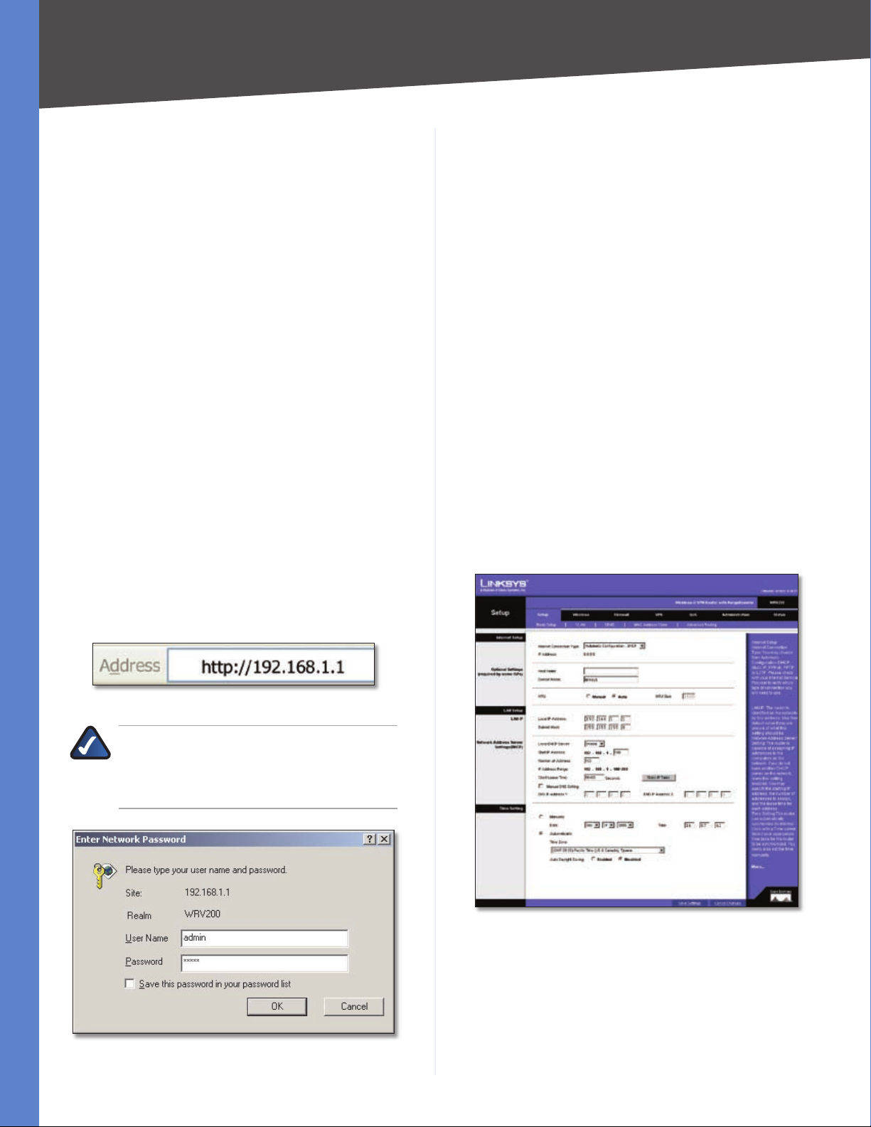
Setup > Basic Settings
How to Access the Web-based Utility
To access the web-based utility, launch Internet Explorer
or Netscape Navigator, and enter the Router’s default
IP address, 192.168.1.1, in the Address field. Then press
Enter.
Address Bar of Web Browser
NOTE: The default IP address is 192.168.1.1. If
the IP address has been changed using DHCP,
enter the assigned IP address instead of the
default.
The first screen that appears is the Basic Setup tab. This
tab allows you to change the Router’s general settings.
Setup > Basic Settings - Automatic Configuration - DHCP
Password Request
Wireless-G VPN Router with RangeBooster
Internet Setup
The Internet Setup section configures the Router for
your Internet connection type. This information can be
obtained from your ISP.
Internet Connection Type The Router supports six types
of connections. Each Setup > Basic Settings screen and
7
Page 13
Chapter 5
available features will differ depending on what kind of
connection type you select. The connection types are:
Automatic Configuration - DHCP
•
Static IP
•
PPPoE
•
PPTP
•
L2TP
•
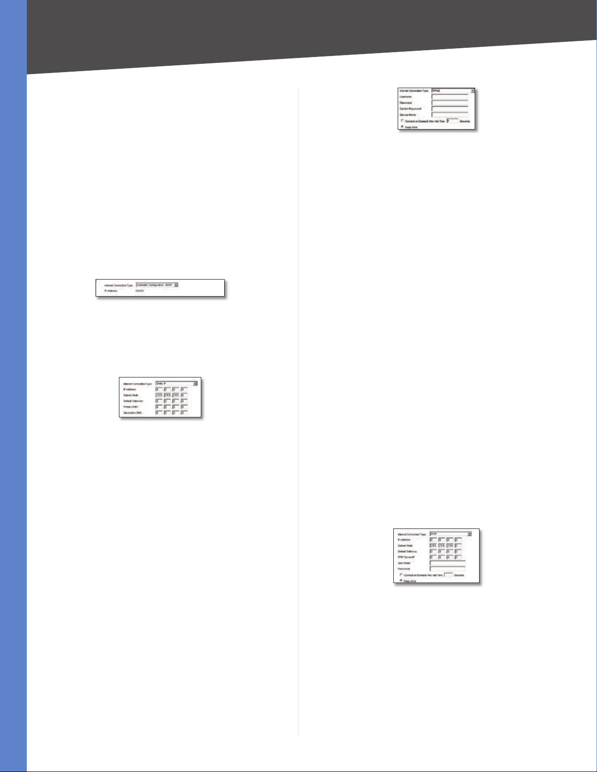
Automatic Configuration - DHCP
By default, the Router’s Configuration Type is set to
Automatic Configuration - DHCP, and it should be kept
only if your ISP supports DHCP or you are connecting
through a dynamic IP address.
Automatic Configuration - DHCP
Static IP
If your connection uses a permanent IP address to connect
to the Internet, then select Static IP.
Static IP
IP Address This is the Router’s IP address, when seen
from the WAN, or the Internet. Your ISP will provide you
with the IP Address you need to specify here.
Subnet Mask This is the Router’s Subnet Mask, as seen
by external users on the Internet (including your ISP). Your
ISP will provide you with the Subnet Mask.
Default Gateway Your ISP will provide you with the
Default Gateway Address, which is the ISP server’s IP
address.
Configuring the Wireless-G Router
PPPoE
User Name and Password/Confirm Password Enter
the User Name and Password provided by your ISP. Then,
enter the password again to confirm it.
Service Name This is required by some service providers.
If your service provider has given you this information,
enter it in this field. If you are not sure if your service
provider requires this information, or if you do not know
the service name, leave this field blank.
Connect on Demand: Max Idle Time You can configure
the Router to cut the Internet connection after it has been
inactive for a specified period of time (Max Idle Time), and
then automatically re-establish the connection as soon
as you attempt to access the Internet again. To activate
Connect on Demand, select the Connect on Demand
option and enter in the Max Idle Time field the number of
seconds of inactivity that must elapse before your Internet
connection is terminated automatically.
Keep Alive If you select this option, the Router will
periodically check your Internet connection. If you are
disconnected, then the Router will automatically reestablish your connection. To use this option, click the
radio button next to Keep Alive.
When you have finished making changes to the screen,
click Save Settings to save the changes, or click Cancel
Changes to undo your changes.
PPTP
Point-to-Point Tunneling Protocol (PPTP) is a service that
applies to connections in Europe and Israel only.
Primary DNS (Required) and Secondary DNS
(Optional) Your ISP will provide you with at least one
DNS (Domain Name System) Server IP Address.
When you have finished making changes to the screen,
click Save Settings to save the changes, or click Cancel
Changes to undo your changes.
PPPoE
Some DSL-based ISPs use PPPoE (Point-to-Point Protocol
over Ethernet) to establish Internet connections. If you are
connected to the Internet through a DSL line, check with
your ISP to see if they use PPPoE. If they do, you will have
to enable PPPoE.
Wireless-G VPN Router with RangeBooster
PPTP
IP Address This is the Router’s IP address, when seen
from the WAN, or the Internet. Your ISP will provide you
with the IP Address you need to specify here.
Subnet Mask This is the Router’s Subnet Mask, as seen
by external users on the Internet (including your ISP). Your
ISP will provide you with the Subnet Mask.
Default Gateway Your ISP will provide you with the
Default Gateway Address.
PPTP Server IP Enter the IP address of the PPTP server.
8
Page 14
Chapter 5
Configuring the Wireless-G Router
User Name and Password Enter the User Name and
Password provided by your ISP.
Connect on Demand: Max Idle Time You can configure
the Router to cut the Internet connection after it has been
inactive for a specified period of time (Max Idle Time), and
then automatically re-establish the connection as soon
as you attempt to access the Internet again. To activate
Connect on Demand, select the Connect on Demand
option and enter in the Max Idle Time field the number of
seconds of inactivity that must elapse before your Internet
connection is terminated automatically.
Keep Alive If you select this option, the Router will
periodically check your Internet connection. If you are
disconnected, then the Router will automatically reestablish your connection. To use this option, click the
radio button next to Keep Alive.
When you have finished making changes to the screen,
click Save Settings to save the changes, or click Cancel
Changes to undo your changes.
L2TP
Layer 2 Tunneling Protocol (L2TP) is a service that tunnels
Point-to-Point Protocol (PPP) across the Internet. It is used
mostly in European countries. Check with your ISP for the
necessary setup information.
seconds of inactivity that must elapse before your Internet
connection is terminated automatically.
Keep Alive If you select this option, the Router will
periodically check your Internet connection. If you are
disconnected, then the Router will automatically reestablish your connection. To use this option, click the
radio button next to Keep Alive.
When you have finished making changes to the screen,
click Save Settings to save the changes, or click Cancel
Changes to undo your changes.
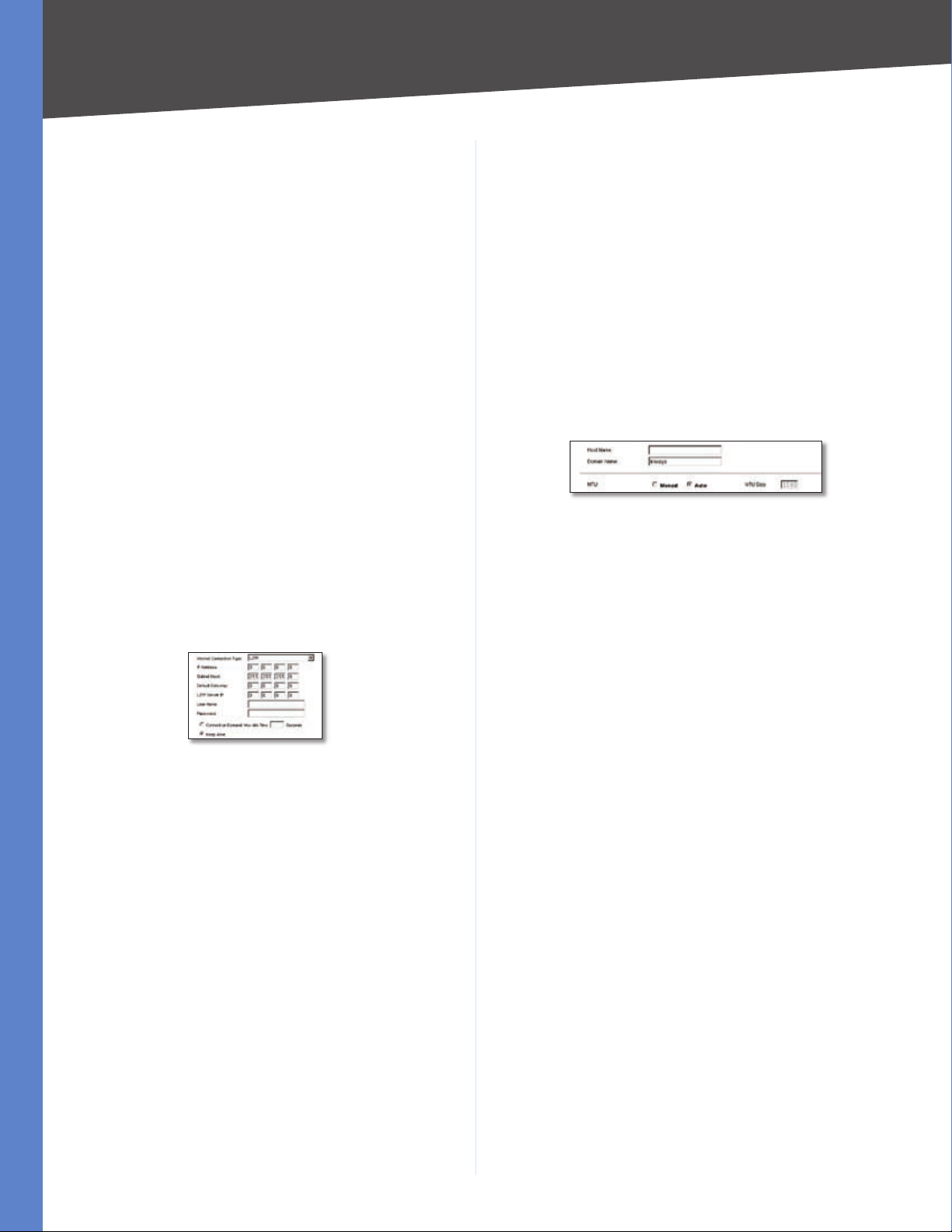
Optional Settings (Required by some ISPs)
Some of these settings may be required by your ISP. Verify
with your ISP before making any changes.
Optional Settings
Host Name and Domain Name These fields allow you
to supply a host and domain name for the Router. Some
ISPs require these names as identification. You may have
to check with your ISP to see if your broadband Internet
service has been configured with a host and domain
name. In most cases, leaving these fields blank will work.
L2TP
IP Address This is the Router’s IP address, when seen
from the WAN, or the Internet. Your ISP will provide you
with the IP Address you need to specify here.
Subnet Mask This is the Router’s Subnet Mask, as seen
by external users on the Internet (including your ISP). Your
ISP will provide you with the Subnet Mask.
Default Gateway Your ISP will provide you with the
Default Gateway Address.
L2TP Server IP Enter the IP address of the L2TP server.
User Name and Password Enter the User Name and
Password provided by your ISP.
Connect on Demand: Max Idle Time You can configure
the Router to cut the Internet connection after it has been
inactive for a specified period of time (Max Idle Time), and
then automatically re-establish the connection as soon
as you attempt to access the Internet again. To activate
Connect on Demand, select the Connect on Demand
option and enter in the Max Idle Time field the number of
MTU The MTU (Maximum Transmission Unit) setting
specifies the largest packet size permitted for network
transmission. Select Manual and enter the value desired.
It is recommended that you leave this value in the 1200
to 1500 range. For most DSL users, it is recommended to
use the value 1492. By default, MTU is set at 1500 when
disabled.
MTU Size When Manual is selected in the MTU field, this
option is enabled. It is recommended that you set this
value within the range of 1200 to 1500, but the value can
be defined between 128 and 1500.
LAN Setup
The LAN Setup section allows you to change the Router’s
local network settings.
LAN IP
The Router’s Local IP Address and Subnet Mask are shown
here. In most cases, you can keep the defaults.
Local IP Address The default value is 192.168.1.1.
Subnet Mask The default value is 255.255.255.0.
Network Address Server Settings (DHCP)
The Router can be used as your network’s DHCP (Dynamic
Host Configuration Protocol) server, which automatically
Wireless-G VPN Router with RangeBooster
9
Page 15
Chapter 5
Configuring the Wireless-G Router
assigns an IP address to each PC on your network. Unless
you already have one, it is highly recommended that you
leave the Router enabled as a DHCP server.
Local DHCP Server DHCP is already enabled by factory
default. If you already have a DHCP server on your network,
set the Router’s DHCP option to Disabled. If you disable
DHCP, assign a static IP address to the Router.
Start IP Address Enter a value for the DHCP server to
start with when issuing IP addresses. This value must be
192.168.1. 2 or greater, but smaller than 192.168.1.254,
because the default IP address for the Router is 192.168.1.1,
and 192.168.1.255 is the broadcast IP address.
Number of Address Enter the maximum number of PCs
that you want the DHCP server to assign IP addresses
to. This number cannot be greater than 253. In order to
determine the DHCP IP Address range, add the starting IP
address (e.g., 100) to the number of DHCP users.
IP Address Range The range of DHCP addresses is
displayed here.
Client Lease Time This is the amount of time a DHCP
client can keep the assigned IP address before it sends a
renewal request to the DHCP server.
The Static IP Table shows the mapping of MAC addresses
to IP addresses. To use this feature, click Static IP Table,
then enter the Static IP Address and MAC address in the
fields, then click Add. To edit an entry, highlight the entry
in the table, click Edit, make your changes in the fields,
then click Add. To remove an entry, highlight the entry,
then click Remove.
Manual DNS Setting To enter the DNS IP addresses
manually, check the box, then enter up to two IP addresses
in the fields provided.
Automatically Select your time zone from the Time Zone
drop-down menu. If you want to enable the Auto Daylight
Savings feature, click Enabled.
When you have finished making changes to the screen,
click Save Settings to save the changes, or click Cancel
Changes to undo your changes.
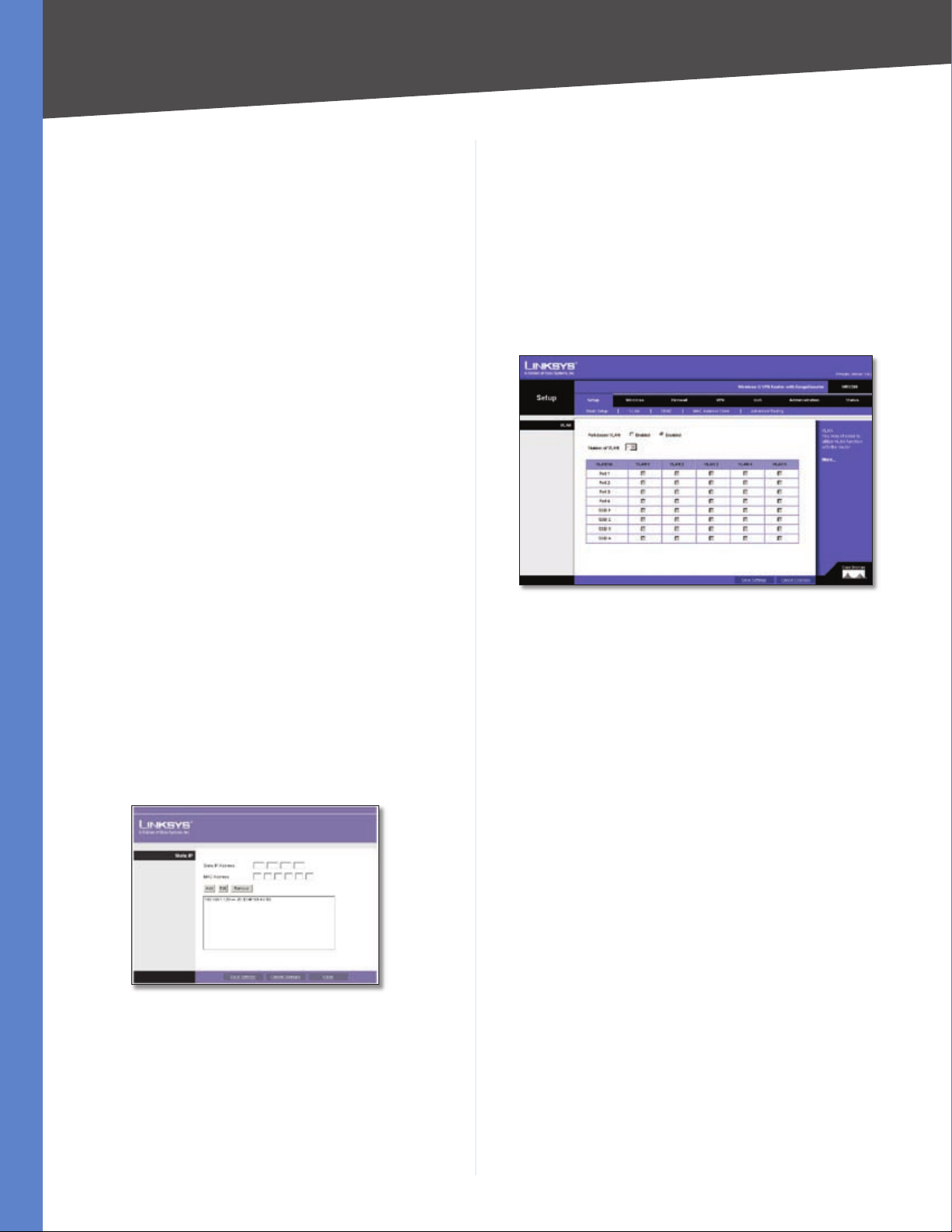
Setup > VLAN
The Setup > VLAN screen allows you to use the Router’s
port-based VLAN feature.
Setup > VLAN
Port-based VLAN Select Enabled to enable the feature.
When enabled, and a VLAN is selected, VLAN1 will be
enabled as a default VLAN, so you will have two VLANs.
Select Disabled to disable the feature. When this feature
is disabled, all LAN ports are on the same LAN.
Number of VLAN Select the number of the VLAN from
the drop-down menu.
VLAN No. Select the VLAN number to associate with the
desired port.
Static IP Table
Time Settings
This is where you set the time for the Router. You can set
the time and date manually or automatically.
Manually Select the date from the Date drop-down
menus. Then enter the time in the Time fields.
Wireless-G VPN Router with RangeBooster
When you have finished making changes to the screen,
click Save Settings to save the changes, or click Cancel
Changes to undo your changes.
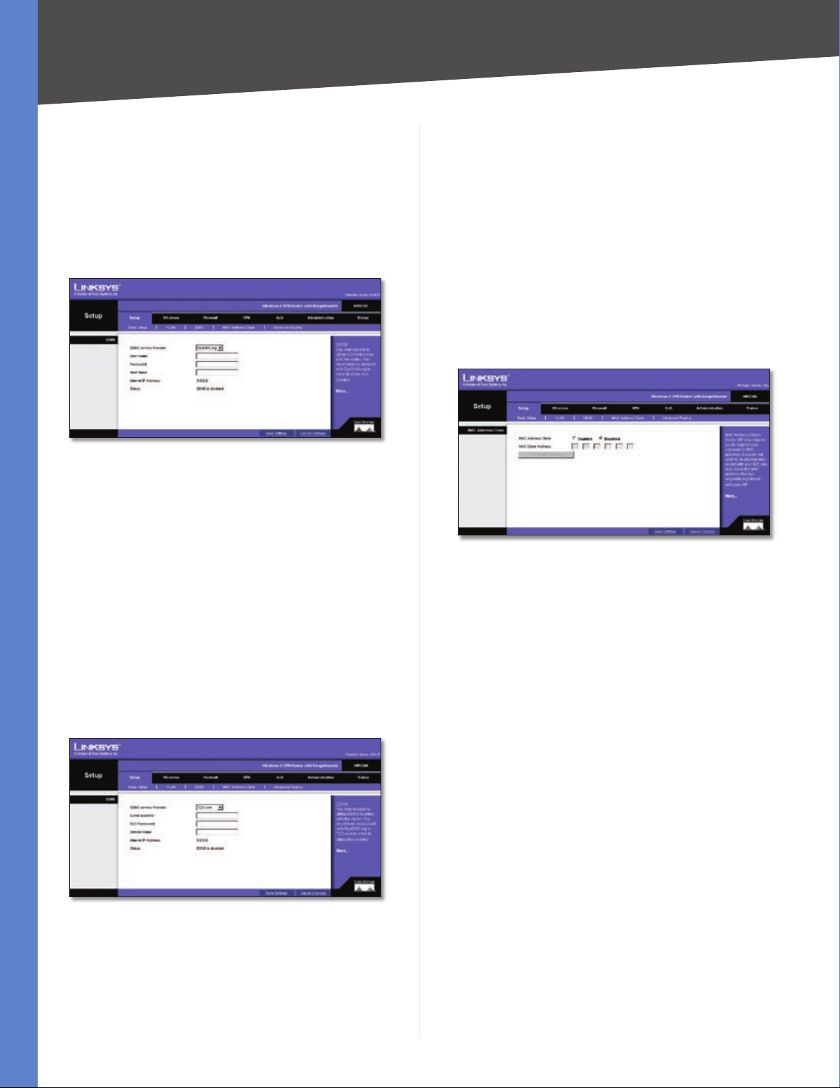
Setup > DDNS
The Router offers a Dynamic Domain Name System (DDNS)
feature. DDNS lets you assign a fixed host and domain
name to a dynamic Internet IP address. It is useful when
you are hosting your own website, FTP server, or other
server behind the Router and your ISP does not give you
a fixed IP address.
Before you can use this feature, you need to sign up for
DDNS service at one of two DDNS service providers,
DynDNS.org or TZO.com.
10
Page 16
Chapter 5
Configuring the Wireless-G Router
DDNS
If your DDNS service is provided by DynDNS.org, then
select DynDNS.org in the drop-down menu. If your DDNS
service is provided by TZO, then select TZO.com. The
features available on the DDNS screen will vary, depending
on which DDNS service provider you use.
DynDNS.org
Setup > DDNS - DynDNS
User Name, Password, and Host Name Enter the User
Name, Password, and Host Name of the account you set
up with DynDNS.org.
Status The status of the DDNS service connection is
displayed here.
When you have finished making changes to the screen,
click Save Settings to save the changes, or click Cancel
Changes to undo your changes.
Setup > MAC Address Clone
Some ISPs require that you register a MAC address. This
feature “clones” your network adapter’s MAC address onto
the Router, and prevents you from having to call your ISP
to change the registered MAC address to the Router’s
MAC address. The Router’s MAC address is a 12-digit code
assigned to a unique piece of hardware for identification.
Internet IP Address The Router’s current Internet IP
Address is displayed here. Because it is dynamic, it will
change.
Status The status of the DDNS service connection is
displayed here.
When you have finished making changes to the screen,
click Save Settings to save the changes, or click Cancel
Changes to undo your changes. For help information,
click More.
TZO.com
Setup > DDNS - TZO
Setup > MAC Address Clone
MAC Address Clone To use MAC address cloning, select
Enabled.
MAC Clone Address Enter the MAC Address registered
with your ISP in this field.
Clone My MAC Address If you want to clone the MAC
address of the PC you are currently using to configure the
Router, then click Clone My MAC Address. The Router
will automatically detect your PC’s MAC address, so you
do not have to call your ISP to change the registered MAC
address to the Router’s MAC address. It is recommended
to use the PC registered with the ISP for this operation.
When you have finished making changes to the screen,
click Save Settings to save the changes, or click Cancel
Changes to undo your changes. For help information,
click More.
Email, TZO Password Key, and Domain Name Enter the
Email Address, TZO Password Key, and Domain Name of
the service you set up with TZO.
Internet IP Address The Router’s current Internet IP
Address is displayed here. Because it is dynamic, this will
change.
Wireless-G VPN Router with RangeBooster
11
Page 17
Chapter 5
Configuring the Wireless-G Router
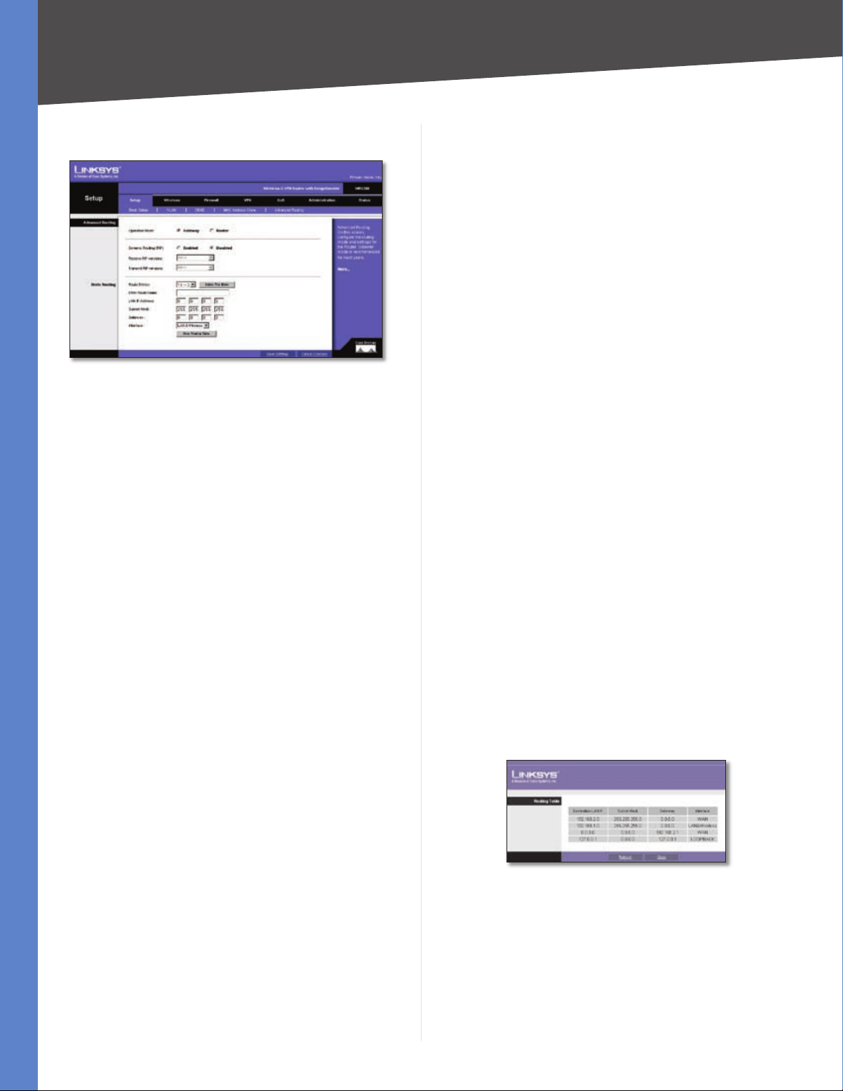
Setup > Advanced Routing
Setup > Advanced Routing
The Setup > Advanced Routing screen allows you to
configure the dynamic and static routing settings.
Operation Mode Select Gateway or Router from the
drop-down menu. If this Router is hosting your network’s
connection to the Internet, keep the default, Gateway,
which will also enable NAT. If you have a different router
hosting your Internet connection, then select Router.
Dynamic Routing
With Dynamic Routing you can enable the Router to
automatically adjust to physical changes in the network’s
layout. The Router, using the RIP protocol, determines
the network packets’ route based on the fewest number
of hops between the source and the destination. The RIP
protocol regularly broadcasts routing information to other
routers on the network.
Dynamic Routing (RIP) To use dynamic routing, click the
Enabled radio button.
Receive RIP Versions To use dynamic routing for
reception of network data, select the protocol you want:
RIPv1 or RIPv2.
Delete This Entry If you need to delete a route, select its
number from the drop-down menu, and click Delete This
Entry.
Enter Router Name Enter the name of your Router.
LAN IP Address The LAN IP Address is the address of the
remote network or host to which you want to assign a
static route. Enter the IP address of the host for which you
wish to create a static route. If you are building a route to
an entire network, be sure that the network portion of the
IP address is set to 0. For example, the Router’s standard IP
address is 192.168.1.1. Based on this address, the address
of the routed network is 192.168.1, with the last digit
determining the Router’s place on the network. Therefore
you would enter the IP address 192.168.1.0 if you wanted
to route to the Router’s entire network, rather than just to
the Router.
Subnet Mask The Subnet Mask (also known as the
Network Mask) determines which portion of an IP address
is the network portion, and which portion is the host
portion. Take, for example, a network in which the Subnet
Mask is 255.255.255.0. This determines (by using the values
255) that the first three numbers of a network IP address
identify this particular network, while the last digit (from 1
to 254) identifies the specific host.
Gateway Enter the IP address of the gateway device that
allows for contact between the Router and the remote
network or host.
Interface Select LAN & Wireless or Internet, depending
on the location of the static route’s final destination.
Show Routing Table Click the Show Routing Table
button to open a screen displaying how packets are
routed through your local network. For each route, the
Destination LAN IP address, Subnet Mask, Gateway, and
Interface are displayed. Click Refresh to update the
information. Click Close to exit this screen.
Transmit RIP Versions To use dynamic routing for
transmission of network data, select the protocol you
want: RIPv1 or RIPv2.
Static Routing
If the Router is connected to more than one network,
you can configure static routes to direct packets to the
destination network (A static route is a pre-determined
pathway that a packet must travel to reach a specific host
or network.) To create a static route, change the following
settings:
Route Entries Select the number of the static route from
the drop-down menu. The Router supports up to 5 static
route entries.
Wireless-G VPN Router with RangeBooster
Setup > Advanced Routing
When you have finished making changes to the screen,
click Save Settings to save the changes, or click Cancel
Changes to undo your changes. For help information,
click More.
12
Page 18
Chapter 5
Configuring the Wireless-G Router
Wireless
The Wireless tab is used to configure the Router’s wireless
network settings.
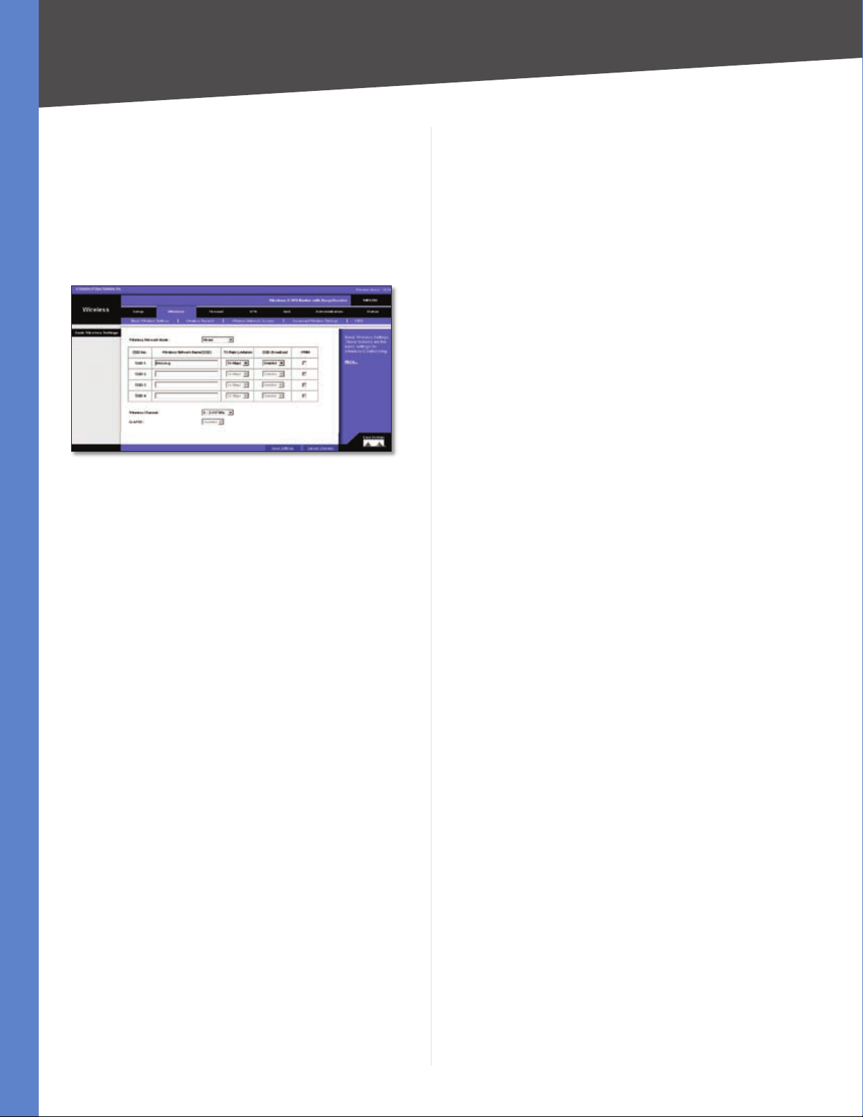
Wireless > Basic Wireless Settings
The basic settings for wireless networking are configured
on this screen.
Wireless > Basic Wireless Settings
Wireless Network Mode
Wireless Network Mode From this drop-down menu,
you can select the wireless standards running on your
network. If you have both 802.11g and 802.11b devices
in your network, keep the default setting, Mixed. If you
have only 802.11g devices, select G-Only. If you have
only 802.11b devices, select B-Only. If you do not have
any 802.11g and 802.11b devices in your network, select
Disable.
Wireless Network Name (SSID) The SSID is the network
name shared among all points in a wireless network.
The SSID must be identical for all devices in the wireless
network. It is case-sensitive and must not exceed 32
characters (use any of the characters on the keyboard).
Make sure this setting is the same for all points in your
wireless network. For added security, you should change
the default SSID (linksys-g) to a unique name.
TX Rate Limitation The rate of data transmission should
be set depending on the speed of your wireless network.
You can select from a range of transmission speeds and
the Router will negotiate the connection speed between
the Router and a wireless client by this rate.
Wireless SSID Broadcast When wireless clients survey
the local area for wireless networks to associate with, they
will detect the SSID broadcast by the Router. To broadcast
the Router’s SSID, keep the default setting, Enable. If you
do not want to broadcast the Router’s SSID, then select
Disabled.
It specifically supports priority tagging and queuing. Click
the WMM check box to enable WMM.
Wireless Channel Select the appropriate channel from
the drop-down menu. All devices in your wireless network
must transmit using the same channel in order to function
correctly. You may need to change the wireless channel to
improve the communication quality.
U-APSD The Unscheduled Automatic Power Save Delivery
(U-APSD) feature is an enhanced power-save mode. Select
Enable to allow the Router to enter power-save mode.
When you have finished making changes to the screen,
click Save Settings to save the changes, or click Cancel
Changes to undo your changes. For help information,
click More.
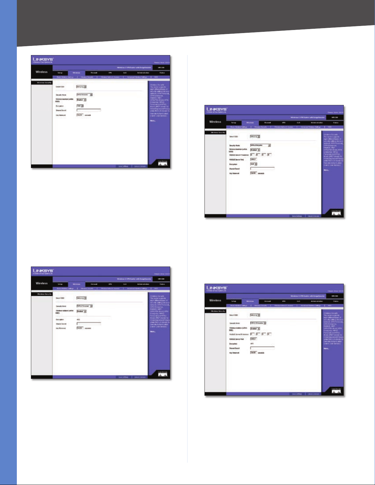
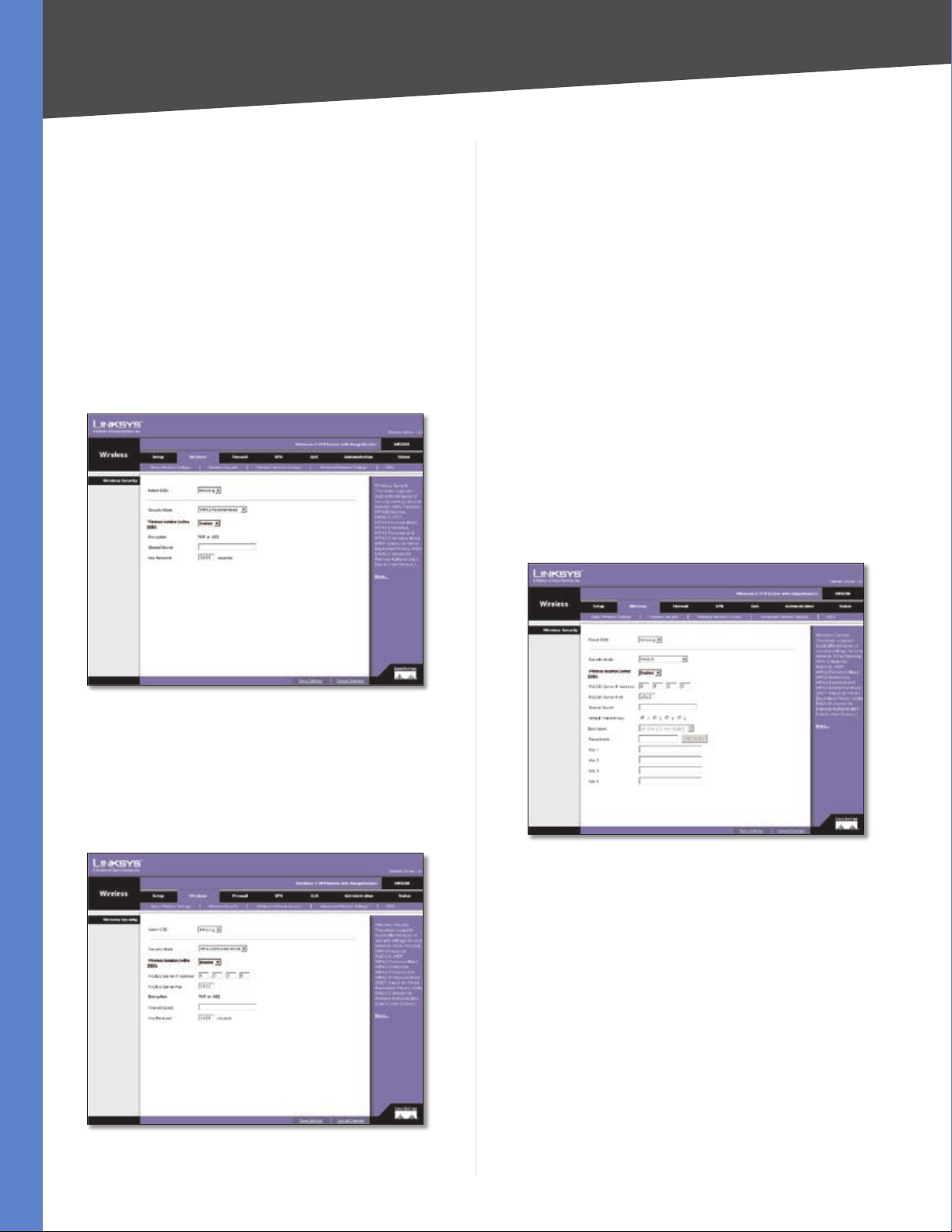
Wireless > Wireless Security
The Wireless Security settings configure the security of
your wireless network. There are eight wireless security
mode options supported by the Router: WPA-Personal,
WPA2-Personal, WPA Enterprise, WPA2 Enterprise, WPA2Personal-Mixed, WPA2-Enterprise Mixed, RADIUS, and
WEP. (WPA stands for Wi-Fi Protected Access, which is a
security standard stronger than WEP encryption. WEP
stands for Wired Equivalent Privacy, while RADIUS stands
for Remote Authentication Dial-In User Service.) For
detailed instructions on configuring wireless security for
the Router, turn to “Appendix B: Wireless Security.”
Select SSID Select the SSID that you want to apply the
wireless security settings to.
Security Mode Select the appropriate security mode for
your network; all devices on your network must use the
same security mode and settings to work correctly.
Wireless isolation within SSID This feature is disabled
by default. Wireless PCs that are associated with the same
SSID can see and transfer files between each other. If
you enable this feature, wireless PCs will not be able to
see each other. This is useful when setting up a wireless
hotspot location.
WPA Personal
WPA gives you two encryption methods with dynamic
encryption keys. Select TKIP or AES from the Encryption
drop-down menu. Enter a Shared Secret (Pre-Shared Key)
of 8-32 characters. Then enter the Key Renewal period,
which instructs the Router how often it should change the
encryption keys.
WMM WMM (Wi-Fi Multimedia) is a component of the IEEE
802.11e wireless LAN standard for quality of service (QoS).
Wireless-G VPN Router with RangeBooster
13
Page 19
Chapter 5
Wireless Security - WPA Personal
When you have finished making changes to the screen,
click Save Settings to save the changes, or click Cancel
Changes to undo your changes. For help information,
click More.
Configuring the Wireless-G Router
server’s IP address. Select TKIP or AES from the WPA
Algorithms drop-down menu. Enter the RADIUS server’s
port number, along with the Shared Secret key, which is
the key shared between the Router and the server. Last,
enter the Key Renewal period, which instructs the Router
how often it should change the encryption keys.
WPA2 Personal
WPA2 gives you the encryption method AES. Enter a
Shared Secret of 8-32 characters. Then enter the Key
Renewal period, which instructs the Router how often it
should change the encryption keys.
Wireless Security - WPA2 Personal
When you have finished making changes to the screen,
click Save Settings to save the changes, or click Cancel
Changes to undo your changes. For help information,
click More.
WPA Enterprise
This option features WPA used in coordination with a
RADIUS server. (This should only be used when a RADIUS
server is connected to the Router.) Enter the RADIUS
Wireless Security - WPA Enterprise
When you have finished making changes to the screen,
click Save Settings to save the changes, or click Cancel
Changes to undo your changes. For help information,
click More.
WPA2 Enterprise
Wireless Security - WPA2 Enterprise
This option features WPA2 used in coordination with a
RADIUS server. (This should only be used when a RADIUS
server is connected to the Router.) Enter the RADIUS
server’s IP address. Enter the RADIUS server’s port number,
along with the Shared Secret key, which is the key shared
between the Router and the server. Last, enter the Key
Wireless-G VPN Router with RangeBooster
14
Page 20
Chapter 5
Configuring the Wireless-G Router
Renewal period, which instructs the Router how often it
should change the encryption keys.
When you have finished making changes to the screen,
click Save Settings to save the changes, or click Cancel
Changes to undo your changes. For help information,
click More.
WPA2 Personal Mixed
WPA2 Personal Mixed gives you either WPA-Personal
(TKIP) or PSK2 (AES) encryption. Enter a Shared Secret of
8-63 characters. Then enter a Key Renewal period, which
instructs the Router how often it should change the
encryption keys.
This option features WPA2 used in coordination with a
RADIUS server. (This should only be used when a RADIUS
server is connected to the Router.) Enter the RADIUS
server’s IP address and port number, along with the shared
secret (authentication key) shared by the Router and the
server. Last, enter the Key Renewal period, which instructs
the Router how often it should change the encryption
keys.
When you have finished making changes to the screen,
click Save Settings to save the changes, or click Cancel
Changes to undo your changes. For help information,
click More.
RADIUS
This option features WEP used in coordination with a
RADIUS server. (This should only be used when a RADIUS
server is connected to the Router.) First, enter the RADIUS
server’s IP address and port number in the RADIUS Server
IP Address and RADIUS Server Port fields. Enter the key
shared between the Router and the server in the Shared
Secret field.
Wireless Security - WPA2 Personal Mixed
When you have finished making changes to the screen,
click Save Settings to save the changes, or click Cancel
Changes to undo your changes. For help information,
click More.
WPA2 Enterprise Mixed
Wireless Security - WPA2 Enterprise Mixed
Wireless Security - RADIUS
To indicate which WEP key to use, select the appropriate
Default Transmit Key number. Then, select the level of WEP
encryption, 64 bits (10 hex digits) or 128 bits (26 hex
digits). Higher encryption levels offer higher levels of
security, but due to the complexity of the encryption, they
may decrease network performance.
Instead of manually entering WEP keys, you can enter
a Passphrase to generate one or more WEP keys. The
Passphrase is case-sensitive and should have no more
than 32 alphanumeric characters. If you want to use
a Passphrase, enter it in the Passphrase field and click
Generate.
If you want to enter the WEP key(s) manually, then enter
it in the Key 1-4 field(s). (Do not leave a field blank, and do
not enter all zeroes; they are not valid key values.) If you are
Wireless-G VPN Router with RangeBooster
15
Page 21
Chapter 5
Configuring the Wireless-G Router
using 64-bit WEP encryption, the key must be exactly 10
hexadecimal characters in length. If you are using 128-bit
WEP encryption, the key must be exactly 26 hexadecimal
characters in length. Valid hexadecimal characters are “0”
to “9” and “A” to “F”.
When you have finished making changes to the screen,
click Save Settings to save the changes, or click Cancel
Changes to undo your changes. For help information,
click More.
WEP
WEP is a basic encryption method, which is not as secure
as WPA. To indicate which WEP key to use, select the
appropriate Default Transmit Key number. Then, select
the level of WEP encryption, 64 bits (10 hex digits) or
128 bits (26 hex digits). Higher encryption levels offer
higher levels of security, but due to the complexity of the
encryption, they may decrease network performance.
Changes to undo your changes. For help information,
click More.
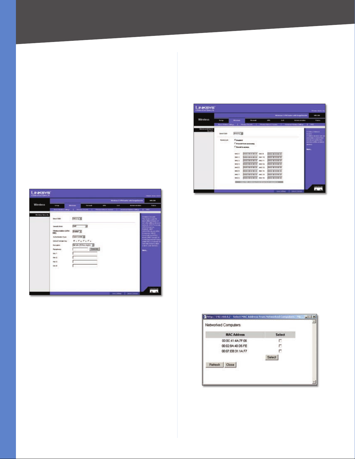
Wireless > Wireless Network Access
This screen allows you to control access to your wireless
network for each SSID.
Wireless > Wireless Network Access
Wireless Network Access
Wireless Security - WEP
Instead of manually entering WEP keys, you can enter
a Passphrase to generate one or more WEP keys. The
Passphrase is case-sensitive and should have no more
than 32 alphanumeric characters. If you want to use
a Passphrase, enter it in the Passphrase field and click
Generate.
If you want to enter the WEP key(s) manually, then enter
it in the Key 1-4 field(s). (Do not leave a field blank, and do
not enter all zeroes; they are not valid key values.) If you are
using 64-bit WEP encryption, the key must be exactly 10
hexadecimal characters in length. If you are using 128-bit
WEP encryption, the key must be exactly 26 hexadecimal
characters in length. Valid hexadecimal characters are “0”
to “9” and “A” to “F”.
When you have finished making changes to the screen,
click Save Settings to save the changes, or click Cancel
Access List To allow the designated computers to
access your network, select Permit to access. To block
the designated computers from accessing your wireless
network, select Prevent from accessing. Click Disabled
to disable the access function.
MAC 1-16 Enter the MAC addresses of the designated
computers. For a more convenient way to add MAC
addresses, click Select MAC Address From Networked
Computers. The Networked Computers screen will appear.
Select the MAC addresses you want. Then click Select.
Click Refresh if you want to refresh the screen. Click Close
to return to the previous screen.
Networked Computers
When you have finished making changes to the screen,
click Save Settings to save the changes, or click Cancel
Changes to undo your changes. For help information,
click More.
Wireless-G VPN Router with RangeBooster
16
Page 22
Chapter 5
Configuring the Wireless-G Router
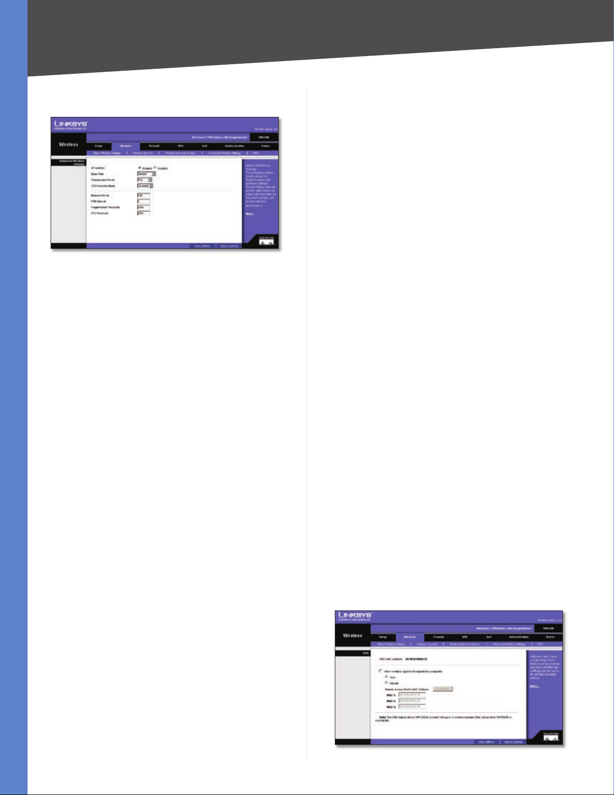
Wireless > Advanced Wireless Settings
Wireless > Advanced Wireless Settings
This tab is used to set up the Router’s advanced wireless
functions. These settings should only be adjusted by an
advanced user as incorrect settings can reduce wireless
performance.
Advanced Wireless Settings
AP Isolation This isolates all wireless clients and wireless
devices on your network from each other. Wireless devices
will be able to communicate with the Router but not with
each other. To use this function, click Enabled. AP Isolation
is disabled by default.
Basic Rate The Basic Rate setting is not actually one rate
of transmission but a series of rates at which the Router
can transmit. The Router will advertise its Basic Rate to the
other wireless devices in your network, so they know which
rates will be used. The Router will also advertise that it will
automatically select the best rate for transmission. The
default setting is Default, when the Router can transmit
at all standard wireless rates (1-2Mbps, 5.5Mbps, 11Mbps,
18Mbps, and 24Mbps). Other options are 1-2Mbps, for
use with older wireless technology, and All, when the
Router can transmit at all wireless rates. The Basic Rate
is not the actual rate of data transmission. If you want to
specify the Router’s rate of data transmission, configure
the Transmission Rate setting.
Transmission Power The amount of transmission power
should be set so that the Router uses only as much
power as needed to reach the farthest device in your
wireless network. This can help prevented unwanted
eavesdropping on your wireless network. You can select
from a range of power levels, from Full, Half, Quarter,
Eighth, or Min. The default setting is Full.
to catch all Wireless-G transmissions but will severely
decrease performance.
Beacon Interval The default value is 100. Enter a value
between 1 and 65,535 milliseconds. The Beacon Interval
value indicates the frequency interval of the beacon. A
beacon is a packet broadcast by the Router to synchronize
the wireless network.
DTIM Interval The default value is 3. This value, between
1 and 255, indicates the interval of the Delivery Traffic
Indication Message (DTIM). A DTIM field is a countdown
field informing clients of the next window for listening to
broadcast and multicast messages. When the Router has
buffered broadcast or multicast messages for associated
clients, it sends the next DTIM with a DTIM Interval value.
Its clients hear the beacons and awaken to receive the
broadcast and multicast messages.
Fragmentation Threshold In most cases, this value
should remain at its default value of 2346. It specifies the
maximum size for a packet before data is fragmented into
multiple packets. If you experience a high packet error rate,
you may slightly increase the Fragmentation Threshold.
Setting the Fragmentation Threshold too low may result
in poor network performance. Only minor reduction of
the default value is recommended.
RTS Threshold The RTS Threshold value should remain at
its default value, 2347. Should you encounter inconsistent
data flow, only minor reduction of the default value, 2347,
is recommended. If a network packet is smaller than the
preset RTS threshold size, the RTS/CTS mechanism will
not be enabled. The Router sends Request to Send (RTS)
frames to a particular receiving station and negotiates
the sending of a data frame. After receiving an RTS, the
wireless station responds with a Clear to Send (CTS) frame
to acknowledge the right to begin transmission.
When you have finished making changes to the screen,
click Save Settings to save the changes, or click Cancel
Changes to undo your changes. For help information,
click More.
Wireless > WDS
CTS Protection Mode CTS (Clear-To-Send) Protection
Mode’s default setting is Auto. The Router will automatically
use CTS Protection Mode when your Wireless-G products
are experiencing severe problems and are not able to
transmit to the Router in an environment with heavy
802.11b traffic. This function boosts the Router’s ability
Wireless-G VPN Router with RangeBooster
Wireless > WDS
17
Page 23

Chapter 5
Configuring the Wireless-G Router
This tab is used for Wireless Distribution System (WDS).
WDS will ONLY work with SSID1. Make sure that the
channel and security settings are the same for all WDS
enabled devices.
WDS allows a wireless signal to be repeated by a repeater.
This mode allows a wireless client to connect to the Router
through a repeater, such as WAP54GP or WAP54GPE, when
operating in the Repeater Mode. This mode allows you to
extend the coverage of the Router by using up to three
repeaters. Select Auto Select to enable the remote access
point when operating in Repeater Mode or select Manual
and enter the MAC address of the repeater.
Click the Site Survey button to view the available access
points.
When you have finished making changes to the screen,
click Save Settings to save the changes, or click Cancel
Changes to undo your changes. For help information,
click More.
Firewall
The Firewall tab is used to control access to the Internet by
users of your internal network.
Firewall > General
The Router’s firewall enhances the security of your
network. You can implement a Stateful Packet Inspection
(SPI) firewall, block anonymous Internet requests, and
enable block mechanisms.
is more difficult for intruders to work their way into your
network. Click the checkbox to block anonymous Internet
requests.
Block Multicast Multicasting allows a transmission to
be forwarded automatically to multiple recipients at the
same time. When Block Multicast is disabled (multicasting
is permitted), the Router allows IP multicast packets to be
forwarded to the appropriate computers in the LAN. Click
the checkbox to filter out multicasting.
Web Block
Proxy Use of WAN proxy servers may compromise the
Router’s security. Denying Filter Proxy will disable access
to any WAN proxy servers. To enable proxy filtering, click
the checkbox next to this option.
Java Java is a programming language for websites. If you
deny Java applets, you run the risk of not having access to
Internet sites created using this programming language.
To enable Java applet filtering, click the checkbox next to
this option.
ActiveX ActiveX is a programming language for websites.
If you deny ActiveX, you run the risk of not having access to
Internet sites created using this programming language.
To enable ActiveX filtering, click the checkbox next to this
option.
Cookies A cookie is data stored on your PC and used
by Internet sites when you interact with them. To enable
cookie filtering, click the checkbox next to this option.
SIP Application Layer Gateway This option allows VoIP
phones to operate behind a NAT router. To enable this
feature, select Enable from the drop-down menu.
Firewall > General
DoS Prevention Denial of Service (DoS) Prevention
checks incoming packets before allowing them to enter
your network. To use this feature, select Enabled from
the drop-down menu. If you do not want DoS Prevention,
select Disabled.
Internet Block
Block Anonymous Internet Requests This keeps your
network from being “pinged” or detected and reinforces
your network security by hiding your network ports, so it
Wireless-G VPN Router with RangeBooster
When you have finished making changes to the screen,
click Save Settings to save the changes, or click Cancel
Changes to undo your changes. For help information,
click More.
Firewall > Port Forwarding
Firewall > Port Forwarding
18
Page 24

Chapter 5
Configuring the Wireless-G Router
The Port Forwarding screen sets up public services on your
network, such as web servers, ftp servers, e-mail servers,
or other specialized Internet applications. (Specialized
Internet applications are any applications that use Internet
access to perform functions such as videoconferencing
or online gaming. Some Internet applications may not
require any forwarding.)
When users send this type of request to your network via
the Internet, the Router will forward those requests to the
appropriate PC. Any PC whose port is being forwarded
must have its DHCP client function disabled and must
have a new static IP address assigned to it because its IP
address may change when using the DHCP function.
Application Name Enter the name you wish to give the
application. Each name can be up to 12 characters.
Port Range Start/End This is the port range. Enter the
number that starts the port range under Start and the
number that ends the range under End.
Protocol Enter the protocol used for this application,
either TCP or UDP, or Both.
IP Address For each application, enter the IP Address of
the PC running the specific application.
Enabled Click the Enabled checkbox to enable port
forwarding for the relevant application.
When you have finished making changes to the screen,
click Save Settings to save the changes, or click Cancel
Changes to undo your changes. For help information,
click More.
Application In this field, enter the name you wish to give
the application. Each name can be up to 12 characters.
Triggered Range Start Port/End Port Enter the number
that starts the triggered port range under Start Port and
the number that ends the range under End Port.
Forwarded Range Start Port/End Port Enter the number
that starts the forwarded port range under Start Port and
the number that ends the range under End Port.
Protocol Enter the protocol used for this application,
either TCP or UDP, or Both.
Enabled Click the Enabled checkbox to enable port
triggering for the relevant application.
When you have finished making changes to the screen,
click Save Settings to save the changes, or click Cancel
Changes to undo your changes. For help information,
click More.
Firewall > DMZ
The DMZ screen allows one local PC to be exposed to
the Internet for use of a special-purpose service such as
Internet gaming and videoconferencing through Software
DMZ. Whereas Port Range Forwarding can only forward a
maximum of 10 ranges of ports, DMZ hosting forwards all
the ports for one PC at the same time.
Firewall > Port Triggering
Firewall > Port Triggering
Port Triggering is used for special Internet applications
whose outgoing ports differ from the incoming ports.
For this feature, the Router will watch outgoing data for
specific port numbers. The Router will remember the
IP address of the computer that sends a transmission
requesting data, so that when the requested data returns
through the Router, the data is pulled back to the proper
computer by way of IP address and port mapping rules.
Wireless-G VPN Router with RangeBooster
Firewall > DMZ
Software DMZ This feature allows one local PC to be
exposed to the Internet for use of a special-purpose service
such as Internet gaming and videoconferencing. To use
this feature, select Enabled. To disable the Software DMZ
feature, select Disabled.
DMZ Host IP Address To expose one PC, enter the
computer’s IP address.
When you have finished making changes to the screen,
click Save Settings to save the changes, or click Cancel
Changes to undo your changes. For help information,
click More.
19
Page 25

Chapter 5
Configuring the Wireless-G Router
Firewall > Access Restriction
The Access Restriction screen allows you to block or allow
specific kinds of Internet usage and traffic during specific
days and times.
Firewall > Access Restriction
Internet Access Policy Access can be managed by a
policy. Use the settings on this screen to establish an
access policy (after Save Settings is clicked). Selecting a
policy from the drop-down menu will display that policy’s
settings. To delete a policy, select that policy’s number
and click Delete. To view all the policies, click Summary.
Status Policies are disabled by default. To enable a policy,
select the policy number from the drop-down menu, and
click the radio button beside Enable.
To create an Internet Access Policy:
Select a number from the Internet Access Policy drop-
1.
down menu.
To enable this policy, click the Enable radio button.
2.
Firewall > URL Filtering
URL filtering is used to block access to specific sites on the
Internet.
Firewall > URL Filtering
To create a URL filtering policy:
Select a number from the URL Filtering Policy drop-
1.
down menu.
Enter a Policy Name in the field provided.
2.
To enable this policy, select Enabled from the Status
3.
menu.
Enter the Start IP Address and End IP Address that will
4.
be affected by the policy. After making your changes,
click Save Settings to apply your changes.
In the URL String field, enter the URL of the Internet site
5.
that this policy will block access to.
Click Save Settings to save the policy’s settings. To
6.
cancel the policy’s settings, click Cancel Changes.
Click Save Settings to save the policy settings you have
entered. Click Cancel Changes to cancel any changes you
have entered. For help information, click More.
Enter a Policy Name in the field provided.
3.
Decide which days and what times you want this policy
4.
to be enforced. Select the individual days during which
the policy will be in effect. Then enter a range of hours
and minutes during which the policy will be in effect,
or select 24 Hours.
You can block access to various services accessed over
5.
the Internet, such as FTP or telnet, by specifying the
TCP/UDP port or the protocol number.
Click Save Settings to save the policy settings you have
entered. Click Cancel Changes to cancel any changes you
have entered. For help information, click More.
Wireless-G VPN Router with RangeBooster
VPN
Virtual Private Networking (VPN) is a security measure
that creates a secure connection between two remote
locations. The security is created by the very specific
settings for the connection. The VPN Tab allows you to
configure your VPN settings to make your network more
secure.
VPN > VPN Client Access
The Router offers a QuickVPN Client utility for Windows
2000 or XP. If the Router has clients using this utility,
then you can designate the QuickVPN clients and their
passwords on the VPN > VPN Client Access screen.
20
Page 26

Chapter 5
VPN > VPN Client Access
User Name Enter a name for the VPN client.
Password Enter a password for the VPN client.
Re-enter to confirm Enter the password again to confirm
it.
Allow user to change password? If you want to let the
user change his or her password from the user’s QuickVPN
client, select Yes.
When you have finished entering the user name and
password of the VPN client, click Add/Save to add the VPN
client to your list. A warning message will appear the first
time you add a VPN client. After all VPN clients are added
to the VPN Client List Table, click Save Settings.
Configuring the Wireless-G Router
Certificate Management
This section allows you to manage the certificate used
for securing the communication between the router and
QuickVPN clients.
Generate Click this button to generate a new certificate
to replace the existing certificate on the router.
Export for Admin Click this button to export the certificate
for administrator. A dialog will ask you to specify where
you want to store your certificate. The default file name
is “WRV200_Admin.pem” but you can use another name.
The certificate for administrator contains the private key
and needs to be stored in a safe place as a backup. If the
router’s configuration is reset to the factory default, this
certificate can be imported and restored on the router.
Export for Client Click this button to export the certificate
for client. A dialog will ask where you want to store your
certificate. The default file name is “WRV200_Client.pem”
but you can use another name. For QuickVPN users to
securely connect to the router, this certificate needs to be
placed in the install directory of the QuickVPN client.
Import Click this button to import a certificate previously
saved to a file using Export for Admin or Export for
Client. Enter the file name in the field or click Browse to
locate the file on your computer, then click Import.
When you have finished making changes to the screen,
click Save Settings to save the changes, or click Cancel
Changes to undo your changes. For help information,
click More.
VPN C;lient Access Warning
VPN Client List Table
No. This is the number assigned to this VPN client. The
Router supports up to 10 QuickVPN clients.
Active If you want to activate this VPN client, click the
Active checkbox.
Username The Username assigned to this VPN client will
be displayed here.
Password The Password assigned to this VPN client will
be displayed here.
Edit/Remove If you want to change the settings for a
VPN client, click Edit and then make your changes. If you
want to delete a VPN client from your list, click Remove.
VPN > VPN Passthrough
The VPN > VPN Passthrough screen is used to allow VPN
tunnels to pass through the Router’s firewall using IPSec,
L2TP, or PPTP protocols.
VPN > VPN Passthrough
IPSec PassThrough Internet Protocol Security (IPSec) is
a suite of protocols used to implement secure exchange
of packets at the IP layer. IPSec Passthrough is enabled by
default to allow IPSec tunnels to pass through the Router.
To disable IPSec Passthrough, select Disabled.
Wireless-G VPN Router with RangeBooster
21
Page 27

Chapter 5
Configuring the Wireless-G Router
PPTP PassThrough Point-to-Point Tunneling Protocol
(PPTP) allows the Point-to-Point Protocol (PPP) to be
tunneled through an IP network. PPTP Passthrough is
enabled by default. To disable it, select Disabled.
L2TP PassThrough Layer 2 Tunneling Protocol is the
method used to enable Point-to-Point sessions via the
Internet on the Layer 2 level. L2TP Passthrough is enabled
by default. To disable L2TP Passthrough, select Disabled.
When you have finished making changes to the screen,
click Save Settings to save the changes, or click Cancel
Changes to undo your changes. For help information,
click More.
VPN > IPSec VPN
The VPN > IPSec VPN screen is used to create and configure
a Virtual Private Network (VPN) tunnel.
traversal is enabled, the Remote Secure Group and Remote
Secure Gateway must be set to Any.
Advanced Settings To define allowable remote private
networks, click Advanced Settings. A screen appears
with the following settings.
Allowable Remote Private Networks You can select
•
Allow All to allow the peer to sit in any private network
that is behind a NAT, or By Manual Setting to indicate
designated private networks manually.
Manual Setting Enter the IP Address and Mask of
•
what you want to accept that remote peer sat behind
NAT. Click the checkbox and then click Save Settings
to save and enable your new configuration.
NAT Traversal Advanced Settings
VPN > IPSec VPN
Tunnel Entry To create a new tunnel, select new. To
configure an existing tunnel, select it from the drop-down
menu.
VPN Tunnel Check the Enabled option to enable this
tunnel.
Tunnel Name Enter a name for this tunnel, such as
“Anaheim Office”.
NAT-Traversal You can enable NAT-Traversal to support
the remote IPSec peer operating behind a NAT device. To
enable NAT traversal, check the Enabled option. If NAT
Local Secure Group
The Local Secure Group is the computer(s) on your LAN
that can access the tunnel.
Type From the drop-down menu, select Subnet, to
include the entire network for the tunnel; select IP
Address if you want a specific computer; or select Host,
which is used with Port Forwarding to direct the traffic to
the correct computer. The screen will change depending
on the selected option. The options are described below.
Subnet Enter the IP Address and Mask of the local
•
VPN Router in the fields provided. To allow access
to the entire IP subnet, enter 0 for the last set of IP
Addresses (e.g., 192.168.1.0).
IP Addr. Enter the IP Address of the local VPN Router.
•
The Mask will be displayed.
Host The VPN tunnel will terminate at the router with
•
this setting. Use Port Range Forwarding to direct traffic
to the correct computer. Refer to the Firewall > Port
Range Forwarding screen.
Remote Secure Group
The Remote Secure Group is the computer(s) on the
remote end of the tunnel that can access the tunnel.
Type From the drop-down menu, select Subnet, to
include the entire network for the tunnel; select IP
address if you want a specific computer; select Host, if
Wireless-G VPN Router with RangeBooster
22
Page 28

Chapter 5
Configuring the Wireless-G Router
the VPN will terminate at the Router, instead of the PC;
or Any, to allow any computer to access the tunnel. The
screen will change depending on the selected option. The
options are described below.
Subnet Enter the IP Address and Mask of the remote
•
VPN router in the fields provided. To allow access to the
entire IP subnet, enter 0 for the last set of IP Addresses
(e.g., 192.168.1.0).
IP Addr. Enter the IP Address of the remote VPN
•
router. The Mask will be displayed.
Host The VPN tunnel will terminate at the router with
•
this setting. Use Port Range Forwarding to direct traffic
to the correct computer. Refer to the Firewall > Port
Range Forwarding screen.
Any Allows any computer to access the tunnel.
•
Remote Secure Gateway
The Remote Secure Gateway is the VPN device, such as a
second VPN router, on the remote end of the VPN tunnel.
Enter the IP Address of the VPN device at the other end
of the tunnel. The remote VPN device can be another
VPN router, a VPN server, or a computer with VPN client
software that supports IPSec. The IP address may either be
static (permanent) or dynamic, depending on the settings
of the remote VPN device.
If the IP Address is static, select IP Addr. and enter the IP
address. Make sure that you have entered the IP address
correctly, or the connection cannot be made. Remember,
this is NOT the IP address of the local VPN Router; it is the
IP address of the remote VPN router or device with which
you wish to communicate. If the IP address is dynamic,
select FQDN for DDNS or Any. If FQDN is selected, enter
the domain name of the remote router, so the Router can
locate a current IP address using DDNS. If Any is selected,
then the Router will accept requests from any IP address.
Key Management
Key Exchange Method IKE is an Internet Key Exchange
protocol used to negotiate key material for Security
Association (SA). IKE uses the Pre-shared Key to
authenticate the remote IDE peer. Select Auto (IKE) for the
Key Exchange Method. Both ends of a VPN tunnel must
use the same mode of key management. The settings
available on this screen may change, depending on the
selection you have made.
Operation Mode Use this option to set the operation
mode to Main (default) or Aggressive. Main Mode
operation is supported in ISAKMP SA establishment.
ISAKMP Encryption Method There are four different
types of encryption: 3DES, AES-128, AES-192, or AES-
256. You may choose any of these, but it must be the
same type of encryption that is being used by the VPN
device at the other end of the tunnel.
ISAKMP Authentication Method There are two types
of authentication: MD5 and SHA (SHA is recommended
because it is more secure). As with encryption, either
of these may be selected, provided that the VPN device
at the other end of the tunnel is using the same type of
authentication.
ISAKMP DH Group This is for Diffie-Hellman key
negotiation. There are 7 groups available for ISAKMP SA
establishment. Group 1024, 1536, 2048, 3072, 4096, 6144,
and 8192 represent different bits used in Diffie-Hellman
mode operation. The default value is 1024.
ISAKMP Key Lifetime(s) This field specifies how long
an ISAKMP key channel should be kept, before being
renegotiated. The default is 28800 seconds.
PFS PFS (Perfect Forward Secrecy) ensures that the initial
key exchange and IKE proposals are secure. To use PFS,
click the Enabled radio button.
IPSec Encryption Method Using encryption also helps
make your connection more secure. There are four
different types of encryption: 3DES, AES-128, AES-192,
or AES-256. You may choose any of these, but it must be
the same type of encryption that is being used by the VPN
device at the other end of the tunnel.
IPSec Authentication Method Authentication acts
as another level of security. There are two types of
authentication: MD5 and SHA (SHA is recommended
because it is more secure). As with encryption, either
of these may be selected, provided that the VPN device
at the other end of the tunnel is using the same type of
authentication. Or, both ends of the tunnel may choose to
disable authentication.
IPSec DH Group This is the same as the ISAKMP DH Group
setting.
IPSec Key Lifetime(s) In this field, you may optionally
select to have the key expire at the end of a time period of
your choosing. Enter the number of seconds you’d like the
key to be used until a re-key negotiation between each
endpoint is completed. The default is 3600 seconds.
Pre-shared Key Enter a series of numbers or letters in
the Pre-shared Key field. Based on this word, which MUST
be entered at both ends of the tunnel, a key is generated
to scramble (encrypt) the data being transmitted over the
tunnel, where it is unscrambled (decrypted). You may use
any combination of up to 24 numbers or letters in this
field. No special characters or spaces are allowed.
Tunnel Options
Dead Peer Detection You can select Dead Peer
Detection (DPD) to detect the status of a remote Peer.
Wireless-G VPN Router with RangeBooster
23
Page 29

Chapter 5
Configuring the Wireless-G Router
DPD will issue DPD packets (ISAKMP format) to query a
remote peer, and wait for a reply to recognize that it is
still alive. There are 3 auxiliary options: Detection Delay(s),
Detection Timeout(s), and DPD Action for DPD.
Detection Delay(s) You can indicate the interval between
DPD query packets. The default value is 30 seconds.
Detection Timeout(s) You can indicate the length of
timeout when DPD cannot hear any DPD reply. The default
value is 120 seconds.
DPD Action When DPD Timeout expires, the DPD will take
DPD Action to deal with the connection. You can select
Wait for Response to still wait for remote peer response, or
select Suspend Connection to stop passively recovering
the connection or select Recover Connection.
If IKE failed more than _times, block this unauthorized
IP for _ seconds This feature is enabled by default. It
enables the Router to block unauthorized IP addresses.
Specify the number of times IKE must fail before the Router
blocks that unauthorized IP address.
Anti-replay This protects the Router from anti-replay
attacks, when people try to capture your authentication
packets in an attempt to gain access. The feature is
enabled by default.
When you have finished making changes to the screen,
click Save Settings to save the changes, or click Cancel
Changes to undo your changes. For help information,
click More.
VPN > VPN Summary
commanded to start/stop connection here. VPN Summary
can help an administrator to manage and examine all
IPSec tunnels status.
Tunnel Name The field displays the name of the tunnel.
Remote Gateway The field displays the remote gateway.
If the pre-configured type is IP Addr., the field displays the
IP address of remote gateway. If the pre-configured type
of remote gateway is Any, the field displays ANY. If the
pre-configured type is FQDN, the field displays the FQDN
string directly.
Remote Group The field displays the remote peer that
is designated for VPN communication after a IPSec VPN
tunnel is established. If the pre-configured type of the
remote group is IP Addr., the field displays the IP address
of the remote peer. If the pre-configured type of the
remote group is Subnet, the field displays the subnet type
“IP Address/Mask”. If the pre-configured type of remote
group is Host or Any, the field displays the “Host” or “Any”
directly.
Local Group The field displays the local peer that is
designated for VPN communication after an IPSec VPN
tunnel is established. If the pre-configured type of local
group is IP Addr., the field displays the IP address of the
local peer. If the pre-configured type of local group is
Subnet, the field displays the subnet type “IP Address/
Mask”. If the pre-configured type of local group is Host,
the field displays the “Host” directly.
Key Methods The field displays the IPSec authentication
and encryption key methods of the Key exchange Method
that is followed with the setting value of the Password
Forward Secrecy.
VPN > VPN Summary
This page summarizes the comprehensive details of IPSec
VPN Tunnels that include Tunnel Name, Remote Gateway,
Remote Group, Local Group, Key Methods, Tunnel Status,
and Start/Stop/Detail Connection. Each field displays
information according to a pre-configured value of IPSec
tunnel separately, and each IPSec tunnel can be easily
Wireless-G VPN Router with RangeBooster
Tunnel Status The field displays the status of IPSec
Tunnel as follows.
C The Tunnel is Connected.
•
T Try to Connect to Remote Peer.
•
Stop The Tunnel is Stopped.
•
D The Tunnel is Disabled.
•
Any The Tunnel always waits for the connection from
•
the remote initiator.
NAT-T The Tunnel enables the NAT-Traversal to allow
•
the remote initiator that is behind the NAT to construct
this IPSec Tunnel.
Start/Stop/Restart Connection You can manually start/
stop IPSec connection according to pre-configured tunnel
settings. If the pre-configured type of remote gateway or
remote group is either Any or NAT-Traversal, the Detail
button can also examine Remote Security Gateway
information.
24
Page 30

Chapter 5
Configuring the Wireless-G Router
Detail Each Tunnel has a Detail button. This button will
become available when a Tunnel Status reveals a “C”, “T”,
“Any”, and “ NAT-T”. When you press the Detail button, a
“VPN Advanced Tunnel Information” screen appears. This
feature provides more detailed information for advanced
configuration and management. VPN Advanced Tunnel
Information will show Advanced Tunnel Information and
Remote Security Gateway.
VPN Log Button Use to check the overall related VPN
behaviors and contact messages of a VPN Tunnel and
VPN Client. Click this button to view the VPN operation
situation. If you want to clear this log information, click
Clear Log Now.
Click the Refresh button to update the on-screen
information.
QoS
Quality of Service (QoS) ensures better service to highpriority service. The QoS tab allows you to configure the
Router’s QoS settings.
QoS > Application-Based QoS
Application-based QoS involves Internet traffic, which
may involve demanding, real-time applications, such as
videoconferencing. To enable Application-based QoS,
you can select either Priority Queue or Bandwidth
Allocation. The remaining fields in the screen depend on
the selection.
Priority Queue
put into High or Low Priority Queue for the egress port of
WAN according to your settings.
Specific Port # You can add up to thirteen additional
applications by entering their respective application port
numbers in the Specific Port # field.
Bandwidth Allocation
QoS > Application Based QoS - Bandwidth Allocation
For each of the three Application Level Gateways (ALGs),
you can choose a Bandwidth Allocation Policy from
Guaranteed and Spare with a specified percentage value
to control the bandwidth utilization from LAN to WAN. It
depends on the specified policy to let the bandwidth be
reserved or shared with the applications. Guaranteed will
reserve specific bandwidth for the applications and Spare
will use the remaining bandwidth for other applications.
User Define Button You can define the policies regarding
source or destination IP, protocol and port number. You
also can mark the DSCP field with specific value to egress
packets. The bandwidth utilization could be controlled
from LAN to WAN.
QoS > Application Based QoS - Priority Queue
Application-based QoS manages information as it is
transmitted from LAN to WAN. Depending on the settings
of the Priority Queue, this feature will assign information a
high or low priority for the five preset applications and up
to thirteen additional applications that you specify.
High Priority and Low Priority For each application,
select High Priority or Low Priority. The packets will be
Wireless-G VPN Router with RangeBooster
When you have finished making changes to the screen,
click Save Settings to save the changes, or click Cancel
Changes to undo your changes. For help information,
click More.
QoS > Port-Based QoS
Port-based QoS ensures better service to a specific LAN port.
QoS > Port-Based QoS
Priority Select the QoS priority for each LAN port. High/
Low setting will queue all egress packets from this port
25
Page 31

Chapter 5
Configuring the Wireless-G Router
according to its priority value. If you select High for the
specific port, the packets received from this port would be
put into High Priority Queue.
Flow Control When this feature is enabled, the wired LAN
ports will exchange control packets with the connected
port before sending packets. If the other end is not able
to process more packets, it will send a pause frame and a
sending port will hold the packets.
Ingress Rate This setting lets the user choose the input
data rate for a port. Packets exceeding this rate will be
dropped. The rates can be 128kbps, 256kbps, 512kbps,
1Mbps, 2Mbps, 4Mbps, 8Mbps, 16Mbps, 32Mbps or no
rate control.
Egress Rate This setting lets the user choose the output
data rate for a port. Packets exceeding this rate will be
dropped. The rates can be 128kbps, 256kbps, 512kbps,
1Mbps, 2Mbps, 4Mbps, 8Mbps 16Mbps, 32Mbps or no
rate control.
When you have finished making changes to the screen,
click Save Settings to save the changes, or click Cancel
Changes to undo your changes. For help information,
click More.
Admin Password
To ensure the Router’s security, you will be asked for your
password when you access the Router’s Web-based Utility.
The default user name and password is admin.
Admin Password You should change the default
password to one of your choice.
Re-enter to confirm Re-enter the Router’s new Password
to confirm it.
Local Router Access
This feature allows you to manage your Router from a local
location, via the Wireless network.
Use HTTPS To use SSL encryption, select Enabled. After
HTTPS is enabled, http requests to the Router’s LAN IP will
be redirected to HTTPS.
Allow Wireless Web Access To enable this feature, select
Enabled.
Remote Router Access
This feature allows you to access the Router from a remote
location, via the Internet.
Administration
The Administration tab provides access to system
administration settings and tools.
Administration > Management
Administration > Management
The Administration > Management screen allows you to
change the Router’s access settings as well as configure
the SNMP and UPnP (Universal Plug and Play) features.
NOTE: When you are in a remote location
and wish to manage the Router, enter
http://<Internet IP Address>: port. Enter
the Router’s specific Internet IP address in
place of <Internet IP Address>, and enter the
Administration Port number in place of the
word port.
Remote Management This feature allows you to manage
the Router from a remote location, via the Internet. To
enable Remote Management, click the Enabled radio
button.
Use HTTPS To use the SSL encryption, select Enabled.
Remote Upgrade If you want to be able to upgrade the
Router remotely from outside the local network, select
Enabled. (You must have the Remote Management
feature enabled as well.) Otherwise, keep the default
setting, Disabled.
Allow Remote IP Address If you want to be able to
access the Router from any external IP address, select Any
IP Address. If you want to specify an external IP address or
range of IP addresses, then select the second option and
complete the fields provided.
Remote Management Port Enter the port number that
will be open to outside access. Otherwise, keep the default
setting, 8080.
Wireless-G VPN Router with RangeBooster
26
Page 32

Chapter 5
Configuring the Wireless-G Router
SNMP
SNMP, Simple Network Management Protocol, is a
network protocol that provides network administrators
with the ability to monitor the status of the Router and
receive notification of any critical events as they occur on
the network.
To enable SNMP, check the Enabled box. To configure
SNMP, complete all fields on this screen. To disable the
SNMP agent, remove the checkmark.
Contact Enter the name of the network administrator for
the Router, as well as a contact number or e-mail address.
Device Name Enter the name of the Router.
Location Enter the location of the Router. For example,
you could include the name of the building, floor
number, and room location, such as Head Office - Floor 5
- Networking 3.
Get Community Enter the password that allows read-
only access to the Router’s SNMP information. The default
name is public.
Set Community Enter the password that allows read/
write access to the Router’s SNMP information. The default
name is private. A name must be entered in this field.
SNMP Trap-Community Enter the password required by
the remote host computer that will receive trap messages
or notices sent by the Router.
SNMP Trusted Host You can restrict access to the Router’s
SNMP information by IP address. Enter the IP address in
the SNMP Trusted Host field. If this field is left blank, then
access is permitted from any IP address.
SNMP Trap-Destination Enter the IP address of
the remote host computer that will receive the trap
messages.
UPnP
Universal Plug and Play (UPnP) allows Windows XP and
Windows 2000 to automatically configure the Router
for various Internet applications, such as gaming and
videoconferencing. To enable UPnP, check the Enabled
box.
Backup and Restore
Backup Configurations To back up the Router’s
configuration, click this button and follow the on-screen
instructions.
Restore Configurations To restore the Router’s
configuration, click this button and follow the on-screen
instructions. (You must have previously backed up the
Router’s configuration.)
When you have finished making changes to the screen,
click Save Settings to save the changes, or click Cancel
Changes to undo your changes. For help information,
click More.
Administration > Log
The Administration > Log screen provides you with options
for email alerts and a log of all incoming and outgoing
URLs or IP addresses for your Internet connection.
Administration > Log
E-Mail Alert To enable the Router to send email alerts in
the event of Denial of Service attacks and the like, select
Enabled. If you do not wish to have email alerts, select
Disabled. The router will send out e-mail logs to a specific
e-mail address.
Mail From Enter the e-mail address so that the receiver
can know where the mail is from.
Recipient To Enter the e-mail address where you want
the alerts to be sent.
Event Types There are ACL, DoS, URL Detect and New
Connection event types for E-Mail Alert. You can select
some of them to enable those event alerts.
System Log You may keep a log of the router’s activities.
This requires the installation of an external log viewer. To
enable System Log, click Enabled.
Logviewer IP Address Enter the address where you want
the system log to be sent.
Event Types There are System, ACL, DoS, URL Detect
and New Connection event types for System Log. You can
select some of them to enable those event logs.
When you have finished making changes to the screen,
click Save Settings to save the changes, or click Cancel
Changes to undo your changes. For help information,
click More.
Wireless-G VPN Router with RangeBooster
27
Page 33

Chapter 5
Configuring the Wireless-G Router
Administration > Diagnostics
The Administration > Diagnostics screen allows you to
check the connections of your network components.
Administration > Diagnostics
Ping Test
IP or URL Address Enter the IP or URL address of the
network device whose connection status you wish to
test.
Packet Size Enter the size of the ping packets.
Times to Ping Enter the number of times that you want
to ping the device: 5, 10, 15, or Unlimited.
click Stop. Click Clear Log to clear the screen. Click Close
to return to the Administration > Diagnostics screen.
For help information, click More.
Administration > Factory Default
Administration > Factory Default
The Administration > Factory Defaults screen allows you
to restore the Router’s configuration to its factory default
settings.
NOTE: Do not restore the factory defaults unless
you are having difficulties with the Router and
have exhausted all other troubleshooting
measures. Once the Router is reset, you will have
to re-enter all of your configuration settings.
Ping Test
Click Start to Ping to start the test. The results of the test
will be displayed in the window. To stop the test, click
Stop. Click Clear Log to clear the screen. Click Close to
return to the Administration > Diagnostics screen.
Traceroute Test
IP or URL Address Enter the IP or URL address of the
network device whose performance you wish to test.
Traceroute Test
Click Start to Traceroute to start the test. The results of
the test will be displayed in the window. To stop the test,
Restore Factory Defaults To reset all configuration
settings to their factory default values, click Restore
Factory Defaults, then click OK to confirm the operation
and continue. When the operation is completed, all
configuration settings will be set to their original factory
default values and all previous settings will be lost.
Administration > Firmware Upgrade
Administration > Firmware Upgrade
The Administration > Firmware Upgrade screen allows you
to upgrade the Router’s firmware. Do not upgrade the
firmware unless you are experiencing problems with the
Router or the new firmware has a feature you want to
use.
Wireless-G VPN Router with RangeBooster
28
Page 34

Chapter 5
NOTE: The Router will lose all of the settings
you have customized. Before you upgrade its
firmware, write down all of your custom settings.
After you upgrade its firmware, you will have to
re-enter all of your configuration settings.
Before upgrading the firmware, download the Router’s
latest firmware upgrade file from www.linksys.com. Then
extract the file to your PC, and perform the steps below.
File Path Enter the name of the extracted firmware
upgrade file or click Browse to locate the file.
Configuring the Wireless-G Router
Start to Upgrade Once you have selected the appropriate
file, click Start to Upgrade and follow the on-screen
instructions to upgrade your firmware.
For help information, click More.
Administration > Reboot
The Administration > Reboot screen allows you to restart the
Router without losing any of its stored settings.
Administration > Reboot
Reboot T
Settings.
o reboot the Router, s
elect Yes
, then click Save
Status
Status > Router
The Status > Router screen displays information about the
Router and its current settings. The on-screen information
will vary depending on the Internet Connection Type
selected on the Setup Tab.
Status > Router
Information
Hardware Version This shows the installed version and
date of the hardware.
Software Version This shows the installed version and
date of the software.
Current Time The current time is displayed here.
MAC Address The MAC Address of the Router’s Internet
interface is displayed here.
Host Name If entered on the Setup Tab, the host name is
displayed here.
Domain Name If entered on the Setup Tab, the domain
name is displayed here.
Internet Connection
Configuration Type This shows the information required
by your ISP for connection to the Internet. This information
was entered on the Setup Tab.
IP Address The Router’s Internet IP Address is displayed
here.
Subnet Mask and Default Gateway The Router’s Subnet
Mask and Default Gateway address are displayed here for
DHCP and static IP connections.
DNS 1-2 Shown here are the DNS (Domain Name Server)
IP addresses currently used by the Router.
Release Available for a DHCP connection, click Release
to release the current IP address of the device connected
to the Router’s Internet port.
Wireless-G VPN Router with RangeBooster
Renew Available for a DHCP connection, click Renew to
renew the current IP address—of the device connected to
the Router’s Internet port—with a current IP address.
Click Refresh to update the on-screen information. For
help information, click More.
29
Page 35

Chapter 5
Configuring the Wireless-G Router
Status > Local Network
The Status > Local Network screen displays information
about the local network.
Status > Local Network
Local Network
Local MAC Address The MAC Address of the Router’s
LAN (local area network) interface is displayed here.
IP Address The Router’s local IP Address is shown here.
Subnet Mask The Router’s Subnet Mask is shown here.
DHCP Server
DHCP Server The status of the DHCP server on the Router
is displayed here.
Start IP The start of the IP address range used by the
device on you local network is displayed here.
Click Refresh to update the on-screen information. For
help information, click More.
Status > Wireless
The Status > Wireless screen displays status information
about your wireless network.
Status > Wireless
Mode As selected from the Wireless tab, this will display
the wireless mode (Mixed, G-Only, or Disabled) used by
the network.
Wireless Channel As entered on the Wireless tab, this
will display the channel on which your wireless network
is broadcasting.
SSID MAC Address As entered on the Wireless tab, this
will display the MAC Address of the SSID listed in the table
and on your network.
End IP The end of the IP address range used by the device
on you local network is displayed here.
DHCP Clients Table Click this button to view a list of
PCs that have been assigned IP addresses by the Router.
The DHCP Active IP Table screen lists the DHCP Server IP
Address, Computer Names, IP Addresses, MAC Addresses,
and length of time until a computer’s assigned IP address
expires. Click Close to return to the Local Network screen.
Click Refresh to update the information.
DHCP Active IP Table
Wireless Network Name (SSID) As entered on the
Wireless tab, this displays the SSID of your network.
Security Mode As selected on the Wireless tab, this will
display what type of wireless security the Router uses.
WMM As entered on the Wireless tab, this displays the
status of the Router’s WMM feature.
Click Refresh to update the on-screen information. For
help information, click More.
Status > System Performance
The Status > System Performance screen displays status
information about network traffic for the Internet, wireless
activities, and wired connectivity.
Wireless-G VPN Router with RangeBooster
30
Page 36

Chapter 5
Configuring the Wireless-G Router
Bytes Received The number of bytes received is shown
here.
Bytes Sent The number of bytes sent is shown here.
Error Packets Received The number of error packets
received is displayed here.
Dropped Packets Received The number of dropped
packets received is displayed here.
Click Refresh to update the on-screen information. For
help information, click More.
Status > VPN Clients
The Status > VPN Client Status screen displays status
information about the Router’s QuickVPN clients.
Status > System Performance
System Performance
Internet/Wireless
Statistics for the network traffic on the Internet connection
and wireless connectivity are shown in five separate
columns.
Connection The status of the connection is shown here.
Packets Received The number of packets received is
displayed here.
Packets Sent The number of packets sent is displayed
here.
Bytes Received The number of bytes received is shown
here.
Bytes Sent The number of bytes sent is shown here.
Error Packets Received The number of error packets
received is displayed here.
Dropped Packets Received The number of dropped
packets received is displayed here.
LAN
Statistics for the network traffic on each of the four LAN
ports are shown in four separate columns.
Connection The status of the connection is shown here.
Packets Received The number of packets received is
displayed here.
Packets Sent The number of packets sent is displayed
here.
Status > VPN Clients
VPN Summary
VPN Client Users Display Select the group of VPN client
users whose information you wish to see.
No. This is the number assigned to the VPN client.
Username The Username assigned to the VPN client will
be displayed here.
Status This is the status of the VPN connection.
Start Time The time the VPN connection began is
displayed here.
End Time The time the VPN connection ended is shown
here.
Duration This is the length of time the VPN connection
has lasted.
Disconnect If you want to disconnect a VPN client, click
this checkbox.
Click Refresh to update the on-screen information.
Click Disconnect to disconnect the VPN clients whose
Disconnect checkboxes have been checked. For help
information, click More.
Wireless-G VPN Router with RangeBooster
31
Page 37

Appendix A
Troubleshooting
Appendix A: Troubleshooting
This appendix provides solutions to problems that may
occur during the installation and operation of the Router.
Read the descriptions below to help solve your problems.
If you can’t find an answer here, check the Linksys website
at www.linksys.com.
I need to set a static IP address on a PC.
The Router, by default, assigns an IP address range of
192.168.1.100 to 192.168.1.149 using the DHCP server on
the Router. To set a static IP address, you can only use the
ranges 192.168.1.2 to 192.168.1.99 and 192.168.1.150 to
192.168.1.254. Each PC or network device that uses TCP/IP
must have a unique address to identify itself in a network.
If the IP address is not unique to a network, Windows will
generate an IP conflict error message. You can assign
a static IP address to a PC by performing the following
steps:
Windows 2000
Click Start, Settings, and Control Panel. Double-click
1.
Network and Dial-Up Connections.
Right-click the Local Area Connection that is
2.
associated with the Ethernet adapter you are using,
and click Properties.
In the Components checked are used by this connection
3.
box, select Internet Protocol (TCP/IP), and click
Properties. Select Use the following IP address.
Enter a unique IP address that is not used by any other
4.
computer on the network connected to the Router. You
can only use an IP address in the ranges 192.168.1.2 to
192.168.1.99 and 192.168.1.151 to 192.168.1.254.
Enter the Subnet Mask, 255.255.255.0.
5.
Enter the Default Gateway, 192.168.1.1 (Router’s
6.
default IP address).
Select Use the following DNS server addresses, and
7.
enter the Preferred DNS server and Alternative DNS
server (provided by your ISP). Contact your ISP or go
on its website to find the information.
Click OK in the Internet Protocol (TCP/IP) Properties
8.
window, and click OK in the Local Area Connection
Properties window.
Restart the computer if asked.
9.
Windows XP
Click Start and Control Panel.
1.
Click the Network and Internet Connections icon
2.
and then the Network Connections icon.
Right-click the Local Area Connection associated
3.
with your Ethernet adapter, and click Properties.
In the This connection uses the following items box,
4.
select Internet Protocol (TCP/IP). Click Properties.
Select Use the following IP address, and enter
5.
a unique IP address that is not used by any other
computer on the network connected to the Router. You
can only use an IP address in the ranges 192.168.1.2 to
192.168.1.99 and 192.168.1.151 to 192.168.1.254.
Enter the Subnet Mask, 255.255.255.0.
6.
Enter the Default Gateway, 192.168.1.1 (Router’s
7.
default IP address).
Select Use the following DNS server addresses, and
8.
enter the Preferred DNS server and Alternative DNS
server (provided by your ISP). Contact your ISP or go
on its website to find the information.
Click OK in the Internet Protocol (TCP/IP) Properties
9.
window. Click OK in the Local Area Connection
Properties window.
I want to test my Internet connection.
Check your TCP/IP settings.
1.
Windows 2000
Click Start, Settings, and Control Panel. Double-
a.
click Network and Dial-Up Connections.
Right-click the Local Area Connection that is
b.
associated with the Ethernet adapter you are using,
and click Properties.
In the Components checked are used by this
c.
connection box, select Internet Protocol (TCP/IP),
and click Properties. Make sure that Obtain an IP
address automatically and Obtain DNS server
address automatically are selected.
Click OK in the Internet Protocol (TCP/IP) Properties
d.
window, and click OK in the Local Area Connection
Properties window.
Restart the computer if asked.
e.
Windows XP
The following instructions are for the default interface
of Windows XP. If you are using the Classic interface (the
icons and menus look like previous Windows versions),
please follow the instructions for Windows 2000.
Wireless-G VPN Router with RangeBooster
Click Start and Control Panel.
a.
32
Page 38

Appendix A
Click the Network and Internet Connections icon
b.
and then the Network Connections icon.
Right-click the Local Area Connection associated
c.
with your Ethernet adapter, and click Properties.
In the This connection uses the following items
d.
box, select Internet Protocol (TCP/IP) and click
Properties. Make sure that Obtain an IP address
automatically and Obtain DNS server address
automatically are selected.
Open a command prompt:
2.
Windows 2000 and XP: Click Start and Run. In the
a.
Open field, type cmd. Press Enter or click OK.
At the command prompt, type ping 192.168.1.1 and
3.
press Enter.
If you get a reply, the computer is communicating
•
with the Router.
If you do NOT get a reply, check the cable, and make
•
sure Obtain an IP address automatically is selected
in the TCP/IP settings for your Ethernet adapter.
At the command prompt, type ping followed by your
4.
Internet IP address and press Enter. The Internet
IP Address can be found in the web interface of the
Router. For example, if your Internet IP address is
1.2.3.4, you would enter ping 1.2.3.4 and press Enter.
Troubleshooting
Make sure you are using the right Internet settings.
3.
Contact your ISP to see if your Internet connection type
is DHCP, Static IP Address, or PPPoE (commonly used by
DSL consumers). Please refer to the Basic Setup section
of “Chapter 5: Configuring the Wireless-G Router” for
details on Internet Connection Type settings.
Make sure you use the right cable. Check to see if the
4.
Internet LED is solidly lit.
Make sure the cable connecting from your cable or
5.
DSL modem is connected to the Router’s Internet port.
Verify that the Status page of the Router’s Web-based
Utility shows a valid IP address from your ISP.
Turn off the computer, Router, and cable/DSL modem.
6.
Wait 30 seconds, and then turn on the Router, cable/
DSL modem, and computer. Check the System
Summary tab of the Router’s Web-based Utility to see
if you get an IP address.
I am not able to access the Router’s Web-based Utility
Setup page.
Refer to “I want to test my Internet connection” above
1.
to verify that your computer is properly connected to
the Router.
Verify that your computer has an IP Address, Subnet
2.
Mask, Gateway, and DNS.
If you get a reply, the computer is connected to
•
the Router.
If you do NOT get a reply, try the ping command
•
from a different computer to verify that your
original computer is not the cause of the problem.
At the command prompt, type ping www.linksys.com
5.
and press Enter.
If you get a reply, the computer is connected to
•
the Internet. If you cannot open a web page, try
the ping command from a different computer to
verify that your original computer is not the cause
of the problem.
If you do NOT get a reply, there may be a problem
•
with the connection. Try the ping command from
a different computer to verify that your original
computer is not the cause of the problem.
I am not getting an IP address on the Internet with my
Internet connection.
Refer to “I want to test my Internet connection” above
1.
to verify that you have connectivity.
If you need to clone the MAC address of your Ethernet
2.
adapter onto the Router, see the MAC Address Clone
section of “Chapter 5: Configuring the Wireless-G
Router” for details.
Set a static IP address on your system; refer to “I need
3.
to set a static IP address” above.
Refer to “I need to remove the proxy settings or the
4.
dial-up pop-up window (for PPPoE users)” below.
I can’t get my Virtual Private Network (VPN) to work
through the Router.
Access the Router’s web interface by going to
http://192.168.1.1 or the IP address of the Router, and go
to the VPN -> VPN Pass Through tab. Make sure you have
IPSec passthrough and/or PPTP passthrough enabled.
VPNs that use IPSec with the ESP (Encapsulation Security
Payload known as protocol 50) authentication will work
fine. At least one IPSec session will work through the
Router; however, simultaneous IPSec sessions may be
possible, depending on the specifics of your VPNs.
VPNs that use IPSec and AH (Authentication Header
known as protocol 51) are incompatible with the Router.
AH has limitations due to occasional incompatibility with
the NAT standard.
Change the IP address for the Router to another subnet
to avoid a conflict between the VPN IP address and your
local IP address. For example, if your VPN server assigns
an IP address 192.168.1.X (X is a number from 1 to 254)
and your local LAN IP address is 192.168.1.X (X is the same
Wireless-G VPN Router with RangeBooster
33
Page 39

Appendix A
Troubleshooting
number used in the VPN IP address), the Router will have
difficulties routing information to the right location. If
you change the Router’s IP address to 192.168.2.1, that
should solve the problem. Change the Router’s IP address
through the Setup tab of the Web-based Utility. If you
assigned a static IP address to any computer or network
device on the network, you need to change its IP address
accordingly to 192.168.2.Y (Y being any number from 1 to
254). Note that each IP address must be unique within the
network.
Your VPN may require port 500/UDP packets to be passed
to the computer that is connecting to the IPSec server.
Refer to “I need to set up online game hosting or use other
Internet applications” below for details.
Check the Linksys website at www.linksys.com for more
information.
I need to set up a server behind my Router.
To use a server like a web, ftp, or mail server, you need
to know the respective port numbers they are using. For
example, port 80 (HTTP) is used for web; port 21 (FTP) is
used for FTP, and port 25 (SMTP outgoing) and port 110
(POP3 incoming) are used for the mail server. You can get
more information by viewing the documentation provided
with the server you installed. Follow these steps to set up
port forwarding through the Router’s Web-based Utility.
We will be setting up web, ftp, and mail servers.
Access the Router’s Web-based Utility by going to
1.
http://192.168.1.1 or the IP address of the Router. Go
to the Firewall -> Port Forwarding tab.
Select the Service from the Application column.
2.
Enter the IP Address of the server that you want the
3.
Internet users to access. For example, if the web
server’s Ethernet adapter IP address is 192.168.1.100,
you would enter 100 in the field provided. Then check
the Enable checkbox for the entry. Consider the
examples below:
Application
HTTP 80 to 80 Both 192.168.1.100 X
FTP 21 to 21 TCP 192.168.1.101 X
SMTP
(outgoing)
POP3
(incoming)
Configure as many entries as you like.
4.
Start
and End
25 to 25 Both 192.168.1.102 X
110 to
110
Protocol
Both 192.168.1.102 X
IP Address
Enable
When you have completed the configuration, click Save
Settings.
I need to set up online game hosting or use other Internet
applications.
If you want to play online games or use Internet
applications, most will work without doing any port
forwarding or DMZ hosting. There may be cases when you
want to host an online game or Internet application. This
would require you to set up the Router to deliver incoming
packets or data to a specific computer. This also applies to
the Internet applications you are using. The best way to
get the information on what port services to use is to go
to the website of the online game or application you want
to use. Follow these steps to set up online game hosting
or use a certain Internet application:
Access the Router’s Web-based Utility by going to
1.
http://192.168.1.1 or the IP address of the Router. Go
to the Firewall -> Port Forwarding tab.
Select the Service from the Application column.
2.
Enter the IP Address of the server that you want the
3.
Internet users to access. For example, if the web
server’s Ethernet adapter IP address is 192.168.1.100,
you would enter 100 in the field provided. Then check
the Enable checkbox for the entry. Consider the
examples below:
Application
UT
Halflife
PC
Anywhere
VPN IPSEC
Configure as many entries as you like.
4.
Start
and End
7777 to
27900
27015 to
27015
5631 to
5631
500 to
500
Protocol
Both 192.168.1.100 X
Both 192.168.1.105 X
UDP 192.168.1.102 X
UDP 192.168.1.100 X
IP Address
Enable
When you have completed the configuration, click Save
Settings.
I can’t get an Internet game, server, or application to work
If you are having difficulties getting any Internet game,
server, or application to function properly, consider
exposing one PC to the Internet using DeMilitarized
Zone (DMZ) hosting. This option is available when an
application requires too many ports or when you are not
sure which port services to use. Make sure you disable all
the forwarding entries if you want to successfully use DMZ
hosting, since forwarding has priority over DMZ hosting.
(In other words, data that enters the Router will be checked
first by the forwarding settings. If the port number that
the data enters from does not have port forwarding, then
.
Wireless-G VPN Router with RangeBooster
34
Page 40

Appendix A
Troubleshooting
the Router will send the data to whichever PC or network
device you set for DMZ hosting.) Follow these steps to set
DMZ hosting:
Access the Router’s Web-based Utility by going to
1.
http://192.168.1.1 or the IP address of the Router. Go
to the Firewall -> Port Forwarding tab.
Disable the entries you have entered for forwarding.
2.
Go to the Firewall -> DMZ tab.
3.
Enter the Ethernet adapter’s IP address of the computer
4.
you want exposed to the Internet. This will bypass the
NAT security for that computer.
Select Enabled to enable DMZ Hosting.
5.
When you have completed the configuration, click Save
Settings.
I forgot my password, or the password prompt always
appears when saving settings to the Router.
Reset the Router to factory defaults by pressing the Reset
button for ten seconds and then releasing it. If you are still
getting prompted for a password when saving settings,
then perform the following steps:
Access the Router’s web interface by going to
1.
http://192.168.1.1 or the IP address of the Router.
Enter the default password admin, and click the
Administration -> Management tab.
Enter a different password in the Admin Password field,
2.
and enter the same password in the Re-enter to confirm
field to confirm the password.
Click Save Settings.
3.
I am a PPPoE user, and I need to remove the proxy
settings or the dial-up pop-up window.
If you have proxy settings, you need to disable these on
your computer. Because the Router is the gateway for the
Internet connection, the computer does not need any
proxy settings to gain access. Please follow these directions
to verify that you do not have any proxy settings and that
the browser you use is set to connect directly to the LAN.
For Microsoft Internet Explorer 5.0 or higher:
Click Start, Settings, and Control Panel. Double-click
1.
Internet Options.
Click the Connections tab.
2.
Click LAN settings and remove anything that is
3.
checked.
Click OK to go back to the previous screen.
4.
Click the option Never dial a connection. This will
5.
remove any dial-up pop-ups for PPPoE users.
For Netscape 4.7 or higher:
Start Netscape Navigator, and click Edit, Preferences,
1.
Advanced, and Proxies.
Make sure you have Direct connection to the Internet
2.
selected on this screen.
Close all the windows to finish.
3.
To start over, I need to set the Router to factory default.
Hold the Reset button for 15 seconds and then release
it. This will return the password, forwarding, and other
settings on the Router to the factory default settings. In
other words, the Router will revert to its original factory
configuration.
I need to upgrade the rmware.
In order to upgrade the firmware with the latest features,
you need to go to the Linksys website and download the
latest firmware at www.linksys.com. Follow these steps:
Go to the Linksys website at www.linksys.com and
1.
download the latest firmware for your Router.
Extract the firmware file on your computer.
2.
To upgrade the firmware, follow the steps in the
3.
Upgrade section found in “Chapter 5: Configuring the
Wireless-G Router”.
My DSL service’s PPPoE is always disconnecting.
PPPoE is not actually a dedicated or always-on connection.
The DSL ISP can disconnect the service after a period of
inactivity, just like a normal phone dial-up connection to
the Internet. There is a setup option to “keep alive” the
connection. This may not always work, so you may need
to re-establish connection periodically.
To connect to the Router, go to the web browser, and
1.
enter http://192.168.1.1 or the IP address of the
Router.
Enter the password, if asked (default password is
2.
admin).
On the Setup -> Basic Setup tab, select the option
3.
Keep Alive, and set the Redial Period option to 20
(seconds).
Click Save Settings.
4.
If the connection is lost again, follow steps 1 and 2 to reestablish connection.
I can’t access my email, web, or VPN, or I am getting
corrupted data from the Internet.
The Maximum Transmission Unit (MTU) setting may need
to be adjusted. By default, the MTU is set at 1500. For most
Wireless-G VPN Router with RangeBooster
35
Page 41

Appendix A
Troubleshooting
DSL users, it is strongly recommended to use MTU 1492. If
you are having difficulties, perform the following steps:
To connect to the Router, go to the web browser, and
1.
enter http://192.168.1.1 or the IP address of the
Router.
Enter the password, if asked (the default password is
2.
admin).
Go to the Setup -> Basic Setup tab.
3.
Look for the MTU option, and select Manual. In the
4.
MTU Size field, enter 1492.
Click Save Settings to continue.
5.
If your difficulties continue, change the MTU Size to
different values. Try this list of values, one value at a time,
in this order, until your problem is solved:
1462
1400
1362
1300
I need to use port triggering.
Port triggering looks at the outgoing port services
used and will trigger the Router to open a specific port,
depending on which port an Internet application uses.
Follow these steps:
When I enter a URL or IP address, I get a time-out error or
am prompted to retry.
Check if other PCs work. If they do, ensure that your
•
workstation’s IP settings are correct (IP Address,
Subnet Mask, Default Gateway, and DNS). Restart the
computer that is having a problem.
If the PCs are configured correctly, but still not
•
working, check the Router. Ensure that it is connected
and powered on. Connect to it and check its settings.
(If you cannot connect to it, check the LAN and power
connections.)
If the Router is configured correctly, check your
•
Internet connection (DSL/cable modem, etc.) to see if
it is working correctly. You can remove the Router to
verify a direct connection.
Manually configure the TCP/IP settings with a DNS
•
address provided by your ISP.
Make sure that your browser is set to connect directly
•
and that any dial-up is disabled. For Internet Explorer,
click Tools, Internet Options, and then the Connection
tab. Make sure that Internet Explorer is set to Never
dial a connection. For Netscape Navigator, click Edit,
Preferences, Advanced, and Proxy. Make sure that
Netscape Navigator is set to Direct connection to the
Internet.
To connect to the Router, go to the web browser, and
1.
enter http://192.168.1.1 or the IP address of the
Router.
Enter the password, if asked (the default password is
2.
admin).
Click the Firewall -> Port Triggering tab.
3.
Enter any name you want to use for the Application
4.
Name.
Enter the Start and End Ports of the Triggered Range.
5.
Check with your Internet application provider for
more information on which outgoing port services it
is using.
Enter the Start and End Ports of the Forwarded Range.
6.
Check with your Internet application provider for
more information on which incoming port services are
required by the Internet application.
Check the Enabled checkbox for the entry.
7.
When you have completed the configuration, click Save
Settings.
I’m trying to access the Router’s Web-based Utility, but I
do not see the login screen. Instead, I see a screen saying,
“404 Forbidden.”
If you are using Internet Explorer, perform the following
steps until you see the Web-based Utility’s login screen
(Netscape Navigator will require similar steps):
Click File. Make sure Work Offline is NOT checked.
1.
Press CTRL + F5. This is a hard refresh, which will force
2.
Internet Explorer to load new web pages, not cached
ones.
Click Tools. Click Internet Options. Click the Security
3.
tab. Click the Default level button. Make sure the
security level is Medium or lower. Then click OK.
I have a QuickVPN tunnel connected to my WRV200, but
I cannot see the computers in the remote network from
Windows Explorer.
QuickVPN tunneling does not support NetBIOS Broadcast.
To access the computers or shared drives on the remote
network, users are advised to use the IP address to identify
the resource.
Wireless-G VPN Router with RangeBooster
I have a Gateway-to-Gateway IPSec VPN tunnel
connected between two WRV200 routers, but the users
36
Page 42

Appendix A
Troubleshooting
in one network cannot see the computers in the remote
network from Windows Explorer.
The WRV200 does not support NetBIOS Broadcast over
a Gateway-to-Gateway IPSec VPN tunnel. To access the
computers or shared drives on the remote network, users
are advised to use the IP address to identify the resource.
Frequently Asked Questions
What is the maximum number of IP addresses that the
Router will support?
The Router will support up to 253 IP addresses.
Is IPSec Passthrough supported by the Router?
Yes, you can enable or disable IPSec Passthrough on the
VPN > VPN Passthrough screen.
Where is the Router installed on the network?
In a typical environment, the Router is installed between
the cable/DSL modem and the LAN. Plug the Router into
the cable/DSL modem’s Ethernet port.
Does the Router support IPX or AppleTalk?
No. TCP/IP is the only protocol standard for the Internet
and has become the global standard for communications.
IPX, a NetWare communications protocol used only to
route messages from one node to another, and AppleTalk,
a communications protocol used on Apple and Macintosh
networks, can be used for LAN to LAN connections, but
those protocols cannot connect from the Internet to the
LAN.
What is Network Address Translation and what is it used
for?
Network Address Translation (NAT) translates multiple IP
addresses on the private LAN to one public address that is
sent out to the Internet. This adds a level of security since
the address of a PC connected to the private LAN is never
transmitted on the Internet. Furthermore, NAT allows the
Router to be used with low cost Internet accounts, such
as DSL or cable modems, when only one TCP/IP address
is provided by the ISP. The user may have many private
addresses behind this single address provided by the ISP.
Does the Router support ICQ send le?
Yes, with the following fix: click ICQ menu => preference
=> connections tab=>, and check I am behind a firewall or
proxy. Then set the firewall time-out to 80 seconds in the
firewall setting. The Internet user can then send a file to a
user behind the Router.
I set up an Unreal Tournament Server, but others on the
LAN cannot join. What do I need to do?
If you have a dedicated Unreal Tournament server running,
you need to create a static IP for each of the LAN computers
and forward ports 7777, 7778, 7779, 7780, 7781, and
27900 to the IP address of the server. You can also use a
port forwarding range of 7777 to 27900. If you want to use
the UT Server Admin, forward another port (8080 usually
works well but is used for remote admin; you may have to
disable this), and then in the [UWeb.WebServer] section of
the server.ini file, set the ListenPort to 8080 (to match the
mapped port above) and ServerName to the IP assigned
to the Router from your ISP.
Can multiple gamers on the LAN get on one game
server and play simultaneously with just one public IP
address?
It depends on which network game or what kind of game
server you are using. For example, Unreal Tournament
supports multi-login with one public IP.
How do I get Half-Life: Team Fortress to work with the
Router?
The default client port for Half-Life is 27005. The computers
on your LAN need to have “+clientport 2700x” added to
the HL shortcut command line; the x would be 6, 7, 8, and
on up. This lets multiple computers connect to the same
server. One problem: Version 1.0.1.6 won’t let multiple
computers with the same CD key connect at the same
time, even if on the same LAN (not a problem with 1.0.1.3).
As far as hosting games, the HL server does not need to be
in the DMZ. Just forward port 27015 to the local IP address
of the server computer.
How can I block corrupted FTP downloads?
If you are experiencing corrupted files when you download
a file with your FTP client, try using another FTP program.
Does the Router support any operating system other
than Windows 2000 or Windows XP?
Yes, but Linksys does not, at this time, provide technical
support for setup, configuration or troubleshooting of any
non-Windows operating systems.
Wireless-G VPN Router with RangeBooster
The web page hangs; downloads are corrupt, or nothing
but junk characters are being displayed on the screen.
What do I need to do?
Force your Ethernet adapter to 10Mbps or half duplex
mode, and turn off the “Auto-negotiate” feature of your
Ethernet adapter as a temporary measure. (Please look
at the Network Control Panel in your Ethernet adapter’s
Advanced Properties tab.) Make sure that your proxy
37
Page 43

Appendix A
Troubleshooting
setting is disabled in the browser. Check our website at
www.linksys.com for more information.
If all else fails in the installation, what can I do?
Reset the Router by holding down the Reset button for ten
seconds. Reset your cable or DSL modem by powering the
unit off and then on. Obtain and flash the latest firmware
release that is readily available on the Linksys website,
www.linksys.com.
How can I be notied of new Router rmware upgrades?
All Linksys firmware upgrades are posted on the
Linksys website at www.linksys.com, where they can
be downloaded for free. The Router’s firmware can be
upgraded using the Web-based Utility. If the Router’s
Internet connection is working well, there is no need
to download a newer firmware version, unless that
version contains new features that you would like to use.
Downloading a more current version of Router firmware
will not enhance the quality or speed of your Internet
connection, and may disrupt your current connection
stability.
Will the Router function in a Macintosh environment?
Yes, but the Router’s setup pages are accessible only
through Internet Explorer 5.0 or Netscape Navigator 5.0 or
higher for Macintosh.
I am not able to get the web conguration screen for the
Router. What can I do?
You may have to remove the proxy settings on your
Internet browser, e.g., Netscape Navigator or Internet
Explorer. Or remove the dial-up settings on your browser.
Check with your browser documentation, and make sure
that your browser is set to connect directly and that any
dial-up is disabled. Make sure that your browser is set
to connect directly and that any dial-up is disabled. For
Internet Explorer, click Tools, Internet Options, and then
the Connection tab. Make sure that Internet Explorer is
set to Never dial a connection. For Netscape Navigator,
click Edit, Preferences, Advanced, and Proxy. Make sure
that Netscape Navigator is set to Direct connection to the
Internet.
If DMZ Hosting is used, does the exposed user share the
public IP with the Router?
No.
Does the Router pass PPTP packets or actively route
PPTP sessions?
The Router allows PPTP packets to pass through.
Is the Router cross-platform compatible?
Any platform that supports Ethernet and TCP/IP is
compatible with the Router.
Does the Router replace a modem? Is there a cable or
DSL modem in the Router?
No, this version of the Router must work in conjunction
with a cable or DSL modem.
Which modems are compatible with the Router?
The Router is compatible with virtually any cable or DSL
modem that supports Ethernet.
How can I check whether I have static or DHCP IP
addresses?
Ask your ISP to find out.
How do I get mIRC to work with the Router?
Under the Firewall -> Port Forwarding tab, set port
forwarding to 113 for the PC on which you are using
mIRC.
What is DMZ Hosting?
Demilitarized Zone (DMZ) allows one IP address (computer)
to be exposed to the Internet. Some applications require
multiple TCP/IP ports to be open. It is recommended that
you set your computer with a static IP if you want to use
DMZ Hosting.
Wireless-G VPN Router with RangeBooster
38
Page 44

Appendix B
Wireless Security Checklist
Appendix B: Wireless Security Checklist
Wireless networks are convenient and easy to install, so
homes with high-speed Internet access are adopting them
at a rapid pace. Because wireless networking operates by
sending information over radio waves, it can be more
vulnerable to intruders than a traditional wired network.
Like signals from your cellular or cordless phones, signals
from your wireless network can also be intercepted. Since
you cannot physically prevent someone from connecting
to your wireless network, you need to take some additional
steps to keep your network secure.
1. Change the default wireless
network name or SSID
Wireless devices have a default wireless network name
or Service Set Identifier (SSID) set by the factory. This
is the name of your wireless network, and can be up
to 32 characters in length. Linksys wireless products
use linksys as the default wireless network name. You
should change the wireless network name to something
unique to distinguish your wireless network from other
wireless networks that may exist around you, but do not
use personal information (such as your Social Security
number) because this information may be available for
anyone to see when browsing for wireless networks.
computer in your home so that only those computers can
access your wireless network.
4. Enable encryption
Encryption protects data transmitted over a wireless
network. Wi-Fi Protected Access (WPA/WPA2) and Wired
Equivalency Privacy (WEP) offer different levels of security
for wireless communication. Currently, devices that are
Wi-Fi certified are required to support WPA2, but are not
required to support WEP.
A network encrypted with WPA/WPA2 is more secure
than a network encrypted with WEP, because WPA/WPA2
uses dynamic key encryption. To protect the information
as it passes over the airwaves, you should enable the
highest level of encryption supported by your network
equipment.
WEP is an older encryption standard and may be the
only option available on some older devices that do not
support WPA.
General Network Security Guidelines
Wireless network security is useless if the underlying
network is not secure.
Password protect all computers on the network and
•
individually password protect sensitive files.
Change passwords on a regular basis.
•
2. Change the default password
For wireless products such as access points, routers, and
gateways, you will be asked for a password when you
want to change their settings. These devices have a default
password set by the factory. The Linksys default password
is admin. Hackers know these defaults and may try to
use them to access your wireless device and change your
network settings. To thwart any unauthorized changes,
customize the device’s password so it will be hard to
guess.
3. Enable MAC address filtering
Linksys routers and gateways give you the ability to
enable Media Access Control (MAC) address filtering. The
MAC address is a unique series of numbers and letters
assigned to every networking device. With MAC address
filtering enabled, wireless network access is provided
solely for wireless devices with specific MAC addresses.
For example, you can specify the MAC address of each
Install anti-virus software and personal firewall
•
software.
Disable file sharing (peer-to-peer). Some applications
•
may open file sharing without your consent and/or
knowledge.
Additional Security Tips
Keep wireless routers, access points, or gateways away
•
from exterior walls and windows.
Turn wireless routers, access points, or gateways
•
off when they are not being used (at night, during
vacations).
Use strong passphrases that are at least eight characters
•
in length. Combine letters and numbers to avoid using
standard words that can be found in the dictionary.
Wireless-G VPN Router with RangeBooster
39
Page 45

Appendix C
Using Linksys QuickVPN for Windows 2000, XP, or Vista
Appendix C: Using Linksys QuickVPN for Windows 2000, XP, or Vista
Overview
This appendix explains how to install and use the Linksys
QuickVPN software that can be downloaded from www.
linksys.com. QuickVPN works with computers running
Windows 2000, XP, or Vista. (Computers using other
operating systems will have to use third-party VPN software.)
For Windows Vista, QuickVPN Client version 1.2.5 or later is
required.
Before You Begin
QuickVPN only works with a Linksys Wireless-G VPN
Router with RangeBooster that is properly configured to
accept a QuickVPN connection. Follow these instructions
to configure the Router’s VPN client settings:
Open the Web-based utility.
1.
Go to the Start menu and then click Run. In the field
provided, enter D:\VPN_Client.exe (if “D” is the letter
of your CD-ROM drive).
The License Agreement screen appears. Click Yes to
2.
accept the agreement and the appropriate files are
copied to the computer.
License Agreement
Click VPN > VPN Client Access.
2.
VPN Client Access Screen
Enter the username in the Username field.
3.
Enter the password in the Password field, and enter it
4.
again in the Re-enter to confirm field.
Click Add/Save.
5.
Click the Active checkbox for VPN Client No. 1.
6.
Click Save Settings.
7.
Copying Files
Finished Installing Files
Click Finished to complete the installation. Proceed to
3.
the section, “Using the Linksys QuickVPN Software”.
Downloading and Installing from the Internet
Go to www.linksys.com and select Products.
1.
Click Business.
2.
Click Router/VPN Solutions.
3.
Click WRV200.
4.
Click Linksys QuickVPN Utility in the More Information
5.
section.
Installing the Linksys QuickVPN Software
Installing from the CD-ROM
Insert the WRV200 CD-ROM into your CD-ROM drive.
1.
Wireless-G VPN Router with RangeBooster
Save the zip file to your PC, and extract the .exe file.
6.
Double-click the .exe file, and follow the on-screen
7.
instructions. Proceed to the next section, “Using the
Linksys QuickVPN Software”.
40
Page 46

Appendix C
Using Linksys QuickVPN for Windows 2000, XP, or Vista
Using the Linksys QuickVPN Software
Double-click the Linksys QuickVPN software icon on
1.
your desktop or in the system tray.
QuickVPN Desktop Icon QuickVPN Tray Icon—
The QuickVPN Login screen will appear. In the Profile
2.
Name field, enter a name for your profile. In the User
Name and Password fields, enter the User Name and
Password that were assigned to you. In the Server
Address field, enter the IP address or domain name of
the Linksys Wireless-G VPN Router with RangeBooster.
In the Port For QuickVPN field, enter the port number
that the QuickVPN client will use to communicate with
the remote VPN router, or keep the default setting,
Auto.
No Connection
QuickVPN Status
To terminate the VPN tunnel, click Disconnect. To
change your password, click Change Password. For
information, click Help.
If you clicked Change Password and have permission
5.
to change your own password, you will see the Connect
Virtual Private Connection screen. Enter your password
in the Old Password field. Enter your new password in
the New Password field. Then enter the new password
again in the Confirm New Password field. Click OK to
save your new password. Click Cancel to cancel your
change. For information, click Help.
Connect Virtual Private Connection
QuickVPN Login
To save this profile, click Save. (If there are multiple
sites to which you will need to create a tunnel, you can
create multiple profiles, but note that only one tunnel
can be active at a time.) To delete this profile, click
Delete. For information, click Help.
To begin your QuickVPN connection, click Connect.
3.
The connection’s progress is displayed: Connecting,
Provisioning, Activating Policy, and Verifying Network.
When your QuickVPN connection is established, the
4.
QuickVPN tray icon turns green, and the QuickVPN
Status screen appears. The screen displays the IP
address of the remote end of the VPN tunnel, the time
and date the VPN tunnel began, and the total length of
time the VPN tunnel has been active.
QuickVPN Tray Icon—
Connection
Wireless-G VPN Router with RangeBooster
NOTE: You can change your password only if
you have been granted that privilege by your
system administrator.
Version Number of the QuickVPN Client
To display the version number of the QuickVPN Client:
Right-click the QuickVPN tray icon, then select About.
1.
The About screen displays the QuickVPN Client version
2.
number.
Click OK to close the About screen.
3.
QuickVPN Client Version Number
41
Page 47

Appendix C
Using Linksys QuickVPN for Windows 2000, XP, or Vista
Distributing Certificates to QuickVPN Users
The following explains how to export a certificate from
the WRV200 for distribution to QuickVPN users, as well as
how to install the certificate on the QuickVPN users’ PCs.
Generate the Certificate as follows:
1.
Log on to the Web-based Utility.
a.
Select VPN, then VPN Client Access.
b.
Click Generate to generate a new certificate.
c.
Click Export for Client and save the certificate as
d.
a .PEM file.
Distribute the certificate to all QuickVPN users.
2.
Each QuickVPN user must then install the certificate as
3.
follows:
Save the certificate into the directory where
a.
the QuickVPN Client is installed. For example:
C:\Program Files\Linksys\QuickVPN Client\
Launch the QuickVPN Client and specify the User
b.
Name, Password, and Server Address (IP address or
domain name).
Click Connect.
c.
For more information on certificate management, go
to section “VPN > VPN Client Access“ in “Chapter 5:
Configuring the Wireless-G Router.”
Wireless-G VPN Router with RangeBooster
42
Page 48

Appendix D
Configuring IPSec with a Windows 2000 or XP Computer
Appendix D:
Configuring
IPSec with
a Windows 2000 or XP
Computer
Introduction
This appendix explains how to establish a secure IPSec
tunnel using preshared keys to join a private network
inside the Router and a Windows 2000 or XP computer.
You can find detailed information on configuring the
Windows 2000 server at the Microsoft website:
Microsoft KB Q252735—How to Configure IPSec Tunneling
in Windows 2000:
http://support.microsoft.com/support/kb/articles/
Q252/7/35.asp
Microsoft KB Q257225—Basic IPSec Troubleshooting in
Windows 2000:
http://support.microsoft.com/support/kb/articles/
Q257/2/25.asp
How to Establish a Secure IPSec Tunnel
Step 1: Create an IPSec Policy
Click Start, select Run, and type secpol.msc in the
1.
Open field. The Local Security Settings screen appears.
Local Security Settings
Right-click IP Security Policies on Local Computer
2.
(Windows XP) or IP Security Policies on Local Machine
(Windows 2000), and click Create IP Security Policy.
Click the Next button, and then enter a name for your
3.
policy (for example, to_Router). Then, click Next.
Deselect the Activate the default response rule
4.
check box, and then click Next.
Click Finish, making sure the Edit check box is
5.
checked.
NOTE: Keep a record of any changes you make.
Those changes will be identical in the Windows
“secpol” application and the Router’s Webbased Utility.
NOTE: The text on your screen may differ from
the text in your instructions regarding the OK
or Close buttons; click the appropriate button
on your screen.
Environment
The IP addresses and other specifics mentioned in this
appendix are for illustration purposes only.
Windows 2000 or Windows XP
IP Address: 140.111.1.2 <= User ISP provides IP Address;
this is only an example.
Subnet Mask: 255.255.255.0
WRV200
WAN IP Address: 140.111.1.1 <= User ISP provides IP
Address; this is only an example.
Step 2: Build Filter Lists
NOTE: Throughout the following section the
term “win” refers to both Windows 2000 and
Windows XP.
NOTE: The text on your screen may differ from
the text in your instructions regarding the OK
or Close buttons; click the appropriate button
on your screen.
Filter List 1: win -> router
In the new policy’s properties screen, verify that the
1.
Rules tab is selected. Deselect the Use Add Wizard
check box, and click Add to create a new rule.
Subnet Mask: 255.255.255.0
LAN IP Address: 192.168.1.1
Subnet Mask: 255.255.255.0
Wireless-G VPN Router with RangeBooster
Rules Tab
43
Page 49

Appendix D
Make sure the IP Filter List tab is selected. Click Add.
2.
IP Filter List Tab
The IP Filter List screen should appear. Enter an
3.
appropriate name, such as win->Router, for the filter
list, and de-select the Use Add Wizard check box.
Then, click Add.
Configuring IPSec with a Windows 2000 or XP Computer
mask 255.255.255.0. (These are the Router’s default
settings. If you have changed these settings, enter
your new values.)
If you want to enter a description for your filter, click
5.
the Description tab and enter the description there.
Click OK. Then, click OK or Close in the IP Filter List
6.
window.
Filter List 2: router -> win
The New Rule Properties screen will appear. Select the
7.
IP Filter List tab, and make sure that win -> Router is
highlighted. Then, click Add.
IP Filter List
The Filters Properties screen will appear. Select the
4.
Addressing tab.
Filters Properties
In the Source address field, select My IP Address. In the
Destination address field, select A specific IP Subnet,
and enter the IP Address 192.168.1.0 and Subnet
New Rules Properties
The IP Filter List screen should appear. Enter an
8.
appropriate name, such as Router->win for the filter
list, and de-select the Use Add Wizard check box.
Click Add.
IP Filter List
The Filters Properties screen will appear. Select the
9.
Addressing tab. In the Source address field, select
A specific IP Subnet, and enter the IP Address
192.168.1.0 and Subnet mask 255.255.255.0. (Enter
your new values if you have changed the default
settings.) In the Destination address field, select My IP
Address.
Wireless-G VPN Router with RangeBooster
44
Page 50

Appendix D
Configuring IPSec with a Windows 2000 or XP Computer
Click the Filter Action tab, and click the filter action
2.
Require Security radio button. Then, click Edit.
Filters Properties
If you want to enter a description for your filter, click
10.
the Description tab and enter the description there.
Click OK or Close and the New Rule Properties screen
11.
appears with the IP Filter List tab selected. The screen
will contain listings for Router->win and win->Router.
Click OK (Windows XP) or Close (Windows 2000) in the
IP Filter List window.
New Rule Properties
Step 3: Configure Individual Tunnel Rules
Tunnel 1: win->Router
Filter Action Tab
On the Security Methods tab, verify that the Negotiate
3.
security option is enabled, and deselect the Accept
unsecured communication, but always respond
using IPSec check box. Select Session key Perfect
Forward Secrecy, and click OK.
Security Methods Tab
Select the Authentication Methods tab, and click
4.
Edit.
On the IP Filter List tab, select filter list win->Router.
1.
IP Filter List Tab
Wireless-G VPN Router with RangeBooster
Authentication Methods Tab
Change the authentication method to Use this string to
5.
protect the key exchange (preshared key), and enter
the preshared key string, such as XYZ12345. Click OK.
45
Page 51

Appendix D
Configuring IPSec with a Windows 2000 or XP Computer
Connection Type Tab
Preshared Key
This new Preshared key will be displayed. Click the
6.
Apply button to continue, if it appears on your screen;
otherwise, proceed to the next step.
New Preshared Key
Select the Tunnel Setting tab, and click The tunnel
7.
endpoint is specified by this IP Address radio button.
Then, enter the Router’s WAN IP Address.
Tunnel 2: Router->win
In the new policy’s Properties screen, make sure
9.
that win -> Router is selected and deselect the Use
Add Wizard check box. Then, click Add to create the
second IP filter.
Properties Screen
Go to the IP Filter List tab, and click the filter list
10.
Router->win.
Tunnel Setting Tab
Select the Connection Type tab, and click All network
8.
connections. Then, click the OK or Close button to
finish this rule.
Wireless-G VPN Router with RangeBooster
IP Filter List Tab
Click the Filter Action tab, and select the filter action
11.
Require Security. Then, click Edit. On the Security
Methods tab, verify that the Negotiate security
option is enabled, and deselect the Accept unsecured
communication, but always respond using IPSec
check box. Select Session key Perfect Forward
Secrecy, and click OK.
46
Page 52

Appendix D
Configuring IPSec with a Windows 2000 or XP Computer
Filter Action Tab
Click the Authentication Methods tab, and verify
12.
that the authentication method Kerberos is selected.
Then, click Edit.
Authentication Methods Tab
Change the authentication method to Use this string
13.
to protect the key exchange (preshared key), and
enter the preshared key string, such as XYZ12345.
(This is a sample key string. Yours should be a key that
is unique but easy to remember.) Then click OK.
New Preshared Key
Click the Tunnel Setting tab. Click the radio button The
15.
tunnel endpoint is specified by this IP Address, and
enter the Windows 2000/XP computer’s IP Address.
Tunnel Setting Tab
Click the Connection Type tab, and select All network
16.
connections. Then click OK or Close to finish.
Preshared Key
This new Preshared key will be displayed. Click the
14.
Apply button to continue, if it appears on your screen;
otherwise, proceed to the next step.
Wireless-G VPN Router with RangeBooster
Connection Type Tab
On the Rules tab, click the OK or Close button to
17.
return to the screen showing the security policies.
Rules Tab
47
Page 53

Appendix D
Configuring IPSec with a Windows 2000 or XP Computer
Step 4: Assign New IPSec Policy
In the IP Security Policies on Local Machine window, rightclick the policy named to_Router, and click Assign. A
green arrow appears in the folder icon.
Local Computer
Step 5: Create a Tunnel Through the Web-Based Utility
Open your web browser, and enter 192.168.1.1 in the
1.
Address field. Press Enter.
When the User name and Password fields appear, enter
2.
the default user name and password, admin. Press
Enter.
Click the VPN tab, then click IPSec VPN.
3.
the Tunnel Name field. This is to allow you to identify
multiple tunnels and does not have to match the
name used at the other end of the tunnel. Set the NAT-
Traversal option to Disabled.
Enter the IP Address and Subnet Mask of the local VPN
5.
Router in the Local Secure Group fields. To allow access
to the entire IP subnet, enter 0 for the last set of IP
Addresses (e.g. 192.168.1.0).
Enter the IP Address and Subnet Mask of the VPN
6.
device at the other end of the tunnel (the remote VPN
Router or device with which you wish to communicate)
in the Remote Secure Group fields.
Select the Key Management.
7.
Select Auto (IKE), then set the Operation Mode to
a.
Main.
Select the ISAKMP encryption method: 3DES, AES-
b.
128, AES-192, or AES-256. The method you select
must be the same type of encryption that is being
used by the VPN device at the other end of the
tunnel.
Select the ISAKMP authentication method: MD5 or
c.
SHA1 (SHA1 is recommended as it is more secure).
As with encryption, the method you select must be
the same type of authentication used by the VPN
device at the other end of the tunnel.
VPN > IPSec VPN
Select the ISAKMP DH Group: 1024, 1536, 2048,
d.
3072, 4096, 6144, or 8192. These represent different
bits used in Diffie-Hellman mode operation.
In the ISAKMP Key Lifetime field, enter a time period
e.
in seconds to have the key expire at the end of the
designated period, or leave the field blank for the
key to last indefinitely.
Select PFS (Perfect Forward Secrecy) to ensure
f.
that the initial key exchange and IKE proposals are
secure.
For IPSec, specify the Encryption Method,
g.
Authentication Method, DH Group, and Key
Lifetime in the same manner as for ISAKMP above.
Enter a series of numbers or letters in the Pre-
h.
shared Key field. You may use any combination of
up to 24 numbers or letters in this field. No special
characters or spaces are allowed.
Click Save Settings to save these changes.
8.
Your tunnel should now be established.
Select the tunnel you wish to create in the Select Tunnel
4.
Entry drop-down box. Then click Enabled next to the
VPN Tunnel option. Enter the name of the tunnel in
Wireless-G VPN Router with RangeBooster
48
Page 54

Appendix E
Gateway-to-Gateway VPN Tunnel
Appendix E: Gateway-to-Gateway VPN Tunnel
Overview
This appendix explains how to configure an IPSec VPN
tunnel between two VPN Routers by example. Two
computers are used to test the liveliness of the tunnel.
Before You Begin
The following is a list of equipment you need:
Two Windows desktop computers (each computer will
•
be connected to a VPN Router)
Two VPN Routers, each connected to the Internet:
•
Wireless-G VPN Router with RangeBooster, model
•
number WRV200
10/100 8-Port VPN Router, model number RV082
•
(Any VPN Router can be deployed, such as the
Linksys 10/100 16-, 8-, or 4-Port VPN Router (model
numbers RV016, RV082, or RV042); however, this
example uses the RV082)
Configuration of the WRV200
Follow these instructions for the first VPN Router,
designated WRV200. The other VPN Router is designated
the RV082.
Launch the web browser for a networked computer,
1.
designated PC 1.
Access the web-based utility of the WRV200. (Refer
2.
to “Chapter 5: Configuring the Wireless-G Router” for
details.)
Click the VPN tab.
3.
Click IPSec VPN.
4.
For the VPN Tunnel setting, select Enable.
5.
Enter a name in the Tunnel Name field.
6.
For the Local Secure Group Type, select Subnet. Enter
7.
the WRV200’s local network settings in the IP Address
and Mask fields.
Configuration when the Remote Gateway Uses a Static IP Address
This example assumes the Remote Gateway is using a
static IP address. If the Remote Gateway uses a dynamic
IP address, refer to “Configuration when the Remote
Gateway Uses a Dynamic IP.”
RV082
WAN: B.B.B.B
LAN: 192.168.1.1
Gateway-to-Gateway IPSec VPN Tunnel - Remote Gateway Using Static IP
NOTE: Each computer must have a network
adapter installed.
WRV200
WAN: A.A.A.A
LAN: 192.168.5.1
WRV200 IPSec VPN Settings
For the Remote Secure Group Type, select Subnet.
8.
Enter the RV082’s local network settings in the
IP Address and Mask fields.
For the Remote Secure Gateway Type, select IP addr.
9.
Enter the RV082’s WAN IP address in the IP Address field.
In the Key Management section, select the appropriate
10.
encryption, authentication, and other key management
settings.
In the Preshared Key field, enter a string for this key, for
11.
example, test1234.
WRV200 Key Management Settings
Wireless-G VPN Router with RangeBooster
49
Page 55

Appendix E
Click Save Settings and proceed to the next section,
12.
“Configuration of the RV082.”
Configuration of the RV082
Follow similar instructions for the RV082.
Launch the web browser for a networked computer,
1.
designated PC 2.
Access the web-based utility of the RV082. (Refer to
2.
the User Guide of the RV082 for details.)
Click the IPSec VPN tab.
3.
Click the Gateway to Gateway tab.
4.
Enter a name in the Tunnel Name field.
5.
For the VPN Tunnel setting, select Enable.
6.
The WAN IP address (B.B.B.B) of the RV082 will be
7.
automatically detected.
For the Local Security Group Type, select Subnet. Enter
the RV082’s local network settings in the IP Address and
Subnet Mask fields.
Gateway-to-Gateway VPN Tunnel
RV082 IPSec Setup Settings
Click Save Settings.
12.
Configuration of PC 1 and PC 2
Verify that PC 1 and PC 2 can ping each other (refer to
Windows Help for more information). If the computers
can ping each other, then you know the VPN tunnel is
configured correctly.
RV082 VPN Settings
For the Remote Security Gateway Type, select IP Only.
8.
Enter the WRV200’s WAN IP address in the IP Address
field.
For the Remote Security Group Type, select Subnet.
9.
Enter the WRV200’s local network settings in the IP
Address and Subnet Mask fields.
In the IPSec Setup section, select the appropriate
10.
encryption, authentication, and other key management
settings. (These should match the settings of the
WRV200.)
In the Preshared Key field, enter a string for this key, for
11.
example, test1234.
Wireless-G VPN Router with RangeBooster
50
Page 56

Appendix E
Configuration when the Remote Gateway Uses a Dynamic IP Address
This example assumes the Remote Gateway is using a
dynamic IP address. If the Remote Gateway uses a static
IP address, refer to “Configuration when the Remote
Gateway Uses a Static IP.”
RV082
Dynamic IP: B.B.B.B with
Domain Name: www.abc.com
LAN: 192.168.1.1
WRV200
WAN: A.A.A.A
LAN: 192.168.5.1
Gateway-to-Gateway VPN Tunnel
WRV200 IPSec VPN Settings
For the Remote Secure Group Type, select Subnet.
8.
Enter the RV082’s local network settings in the IP
Address and Subnet Mask fields.
For the Remote Secure Gateway Type, select FQDN.
9.
Enter the RV082’s domain name in the field provided.
In the Key Management section, select the appropriate
10.
encryption, authentication, and other key management
settings.
Gateway-to-Gateway IPSec VPN Tunnel - Remote Gateway Using
NOTE: Each computer must have a network
adapter installed.
Dynamic IP
Configuration of the WRV200
Follow these instructions for the first VPN Router,
designated WRV200. The other VPN Router is designated
the RV082.
Launch the web browser for a networked computer,
1.
designated PC 1.
Access the web-based utility of the WRV200. (Refer
2.
to “Chapter 5: Configuring the Wireless-G Router” for
details.)
Click the VPN tab.
3.
Click IPSec VPN.
4.
For the IPSec VPN Tunnel setting, select Enable.
5.
Enter a name in the Tunnel Name field.
6.
For the Local Secure Group Type, select Subnet. Enter
7.
the WRV200’s local network settings in the IP Address
and Mask fields.
In the Preshared Key field, enter a string for this key, for
11.
example, test1234.
WRV200 Key Management Settings
Click Save Settings and proceed to the next section,
12.
“Configuration of the RV082.”
Configuration of the RV082
Follow similar instructions for the RV082.
Launch the web browser for a networked computer,
1.
designated PC 2.
Access the Web-based Utility of the RV082. (Refer to
2.
the User Guide of the RV082 for details.)
Click the IPSec VPN tab.
3.
Click the Gateway to Gateway tab.
4.
Enter a name in the Tunnel Name field.
5.
Wireless-G VPN Router with RangeBooster
For the VPN Tunnel setting, select Enable.
6.
The WAN IP address (B.B.B.B) of the RV082 will be
7.
automatically detected.
51
Page 57

Appendix E
Gateway-to-Gateway VPN Tunnel
For the Local Security Group Type, select Subnet. Enter
the RV082’s local network settings in the IP Address and
Subnet Mask fields.
RV082 VPN Settings
For the Remote Security Gateway Type, select IP
8.
address. Enter the WRV200’s WAN IP address in the IP
Address field.
For the Remote Security Group Type, select Subnet.
9.
Enter the WRV200’s local network settings in the IP
Address and Subnet Mask fields.
In the IPSec Setup section, select the appropriate
10.
encryption, authentication, and other key management
settings. (These should match the settings of the
WRV200.)
In the Preshared Key field, enter a string for this key, for
11.
example, test1234.
IP address, refer to “Configuration when the Remote
Gateway Uses a Dynamic IP.”
RV082
Dynamic IP: B.B.B.B with
Domain Name: www.abc.com
LAN: 192.168.1.1
Gateway-to-Gateway IPSec VPN Tunnel - Both Gateways Using
Dynamic IP
NOTE: Each computer must have a network
adapter installed.
WRV200
Dynamic IP: A.A.A.A
with Domain Name:
www.xyz.com
LAN: 192.168.5.1
Configuration of the WRV200
Follow these instructions for the first VPN Router,
designated WRV200. The other VPN Router is designated
the RV082.
RV082 IPSec Setup Settings
Click Save Settings.
12.
Configuration of PC 1 and PC 2
Verify that PC 1 and PC 2 can ping each other (refer to
Windows Help for more information). If the computers
can ping each other, then you know the VPN tunnel is
configured correctly.
Configuration when Both Gateways Use Dynamic IP Addresses
This example assumes both Gateways are using dynamic
IP addresses. If only the Remote Gateway uses a dynamic
Launch the web browser for a networked computer,
1.
designated PC 1.
Access the web-based utility of the WRV200. (Refer
2.
to “Chapter 5: Configuring the Wireless-G Router” for
details.)
Click the VPN tab.
3.
Click IPSec VPN.
4.
For the IPSec VPN Tunnel setting, select Enable.
5.
Enter a name in the Tunnel Name field.
6.
For the Local Secure Group Type, select Subnet. Enter
7.
the WRV200’s local network settings in the IP Address
and Mask fields.
WRV200 IPSec VPN Settings
Wireless-G VPN Router with RangeBooster
52
Page 58

Appendix E
For the Remote Secure Group Type, select Subnet.
8.
Enter the RV082’s local network settings in the IP
Address and Mask fields.
For the Remote Secure Gateway Type, select FQDN.
9.
Enter the RV082’s domain name in the field provided.
In the Key Management section, select the appropriate
10.
encryption, authentication, and other key management
settings.
In the Preshared Key field, enter a string for this key, for
11.
example, test1234.
Gateway-to-Gateway VPN Tunnel
RV082 VPN Settings
For the Remote Security Gateway Type, select IP by
8.
DNS Resolved. Enter the WRV200’s domain name in
the field provided.
For the Remote Security Group Type, select Subnet.
9.
Enter the WRV200’s local network settings in the IP
Address and Subnet Mask fields.
In the IPSec Setup section, select the appropriate
10.
encryption, authentication, and other key management
settings. (These should match the settings of the
WRV200.)
WRV200 Key Management Settings
Click Save Settings and proceed to the next section,
12.
“Configuration of the RV082.”
Configuration of the RV082
Follow similar instructions for the RV082.
Launch the web browser for a networked computer,
1.
designated PC 2.
Access the Web-based Utility of the RV082. (Refer to
2.
the User Guide of the RV082 for details.)
Click the IPSec VPN tab.
3.
Click the Gateway to Gateway tab.
4.
Enter a name in the Tunnel Name field.
5.
For the VPN Tunnel setting, select Enable.
6.
The WAN IP address (B.B.B.B) of the RV082 will be
7.
automatically detected.
For the Local Security Group Type, select Subnet. Enter
the RV082’s local network settings in the IP Address and
Subnet Mask fields.
In the Preshared Key field, enter a string for this key, for
11.
example, test1234.
RV082 IPSec Setup Settings
Click Save Settings.
12.
Configuration of PC 1 and PC 2
Verify that PC 1 and PC 2 can ping each other (refer to
Windows Help for more information). If the computers
can ping each other, then you know the VPN tunnel is
configured correctly.
Wireless-G VPN Router with RangeBooster
53
Page 59

Appendix F
Glossary
Appendix F: Glossary
This glossary contains some basic networking terms you
may come across when using this product.
WEB: For additional terms, please visit the
glossary at www.linksys.com/glossary
Access Point
computers and other devices to communicate with a
wired network. Also used to expand the range of a wireless
network.
Ad-hoc A group of wireless devices communicating
directly with each other (peer-to-peer) without the use of
an access point.
AES (Advanced Encryption Standard) A security method
that uses symmetric 128-bit block data encryption.
Bandwidth The transmission capacity of a given device
or network.
Bit A binary digit.
Boot To start a device and cause it to start executing
instructions.
Broadband An always-on, fast Internet connection.
Browser An application program that provides a way to
look at and interact with all the information on the World
Wide Web.
Byte A unit of data that is usually eight bits long
Cable Modem A device that connects a computer to the
cable television network, which in turn connects to the
Internet.
Daisy Chain A method used to connect devices in a
series, one after the other.
DDNS (Dynamic Domain Name System) Allows the
hosting of a website, FTP server, or e-mail server with a
fixed domain name (e.g., www.xyz.com) and a dynamic IP
address.
Default Gateway A device that forwards Internet traffic
from your local area network.
DHCP (Dynamic Host Configuration Protocol) A
networking protocol that allows administrators to assign
temporary IP addresses to network computers by “leasing”
an IP address to a user for a limited amount of time, instead
of assigning permanent IP addresses.
A device that allows wireless-equipped
DMZ (Demilitarized Zone)
protection from one PC, allowing it to be “seen” from the
Internet.
DNS (Domain Name Server) The IP address of your ISP’s
server, which translates the names of websites into IP
addresses.
Domain A specific name for a network of computers.
Download To receive a file transmitted over a network.
DSL (Digital Subscriber Line) An always-on broadband
connection over traditional phone lines.
Dynamic IP Address A temporary IP address assigned by
a DHCP server.
EAP (Extensible Authentication Protocol) A general
authentication protocol used to control network access.
Many specific authentication methods work within this
framework.
Encryption Encoding data transmitted in a network.
Ethernet IEEE standard network protocol that specifies
how data is placed on and retrieved from a common
transmission medium.
Firewall A set of related programs located at a network
gateway server that protects the resources of a network
from users from
Firmware The programming code that runs a networking
device.
FTP (File Transfer Protocol) A protocol used to transfer
files over a TCP/IP network.
Full Duplex The ability of a networking device to receive
and transmit data simultaneously.
Gateway A device that interconnects networks with
different, incompatible communications protocols.
Half Duplex Data transmission that can occur in two
directions over a single line, but only one direction at a
time.
HTTP (HyperText Transport Protocol) The
communications protocol used to connect to servers on
the World Wide Web.
Infrastructure A wireless network that is bridged to a
wired network via an access point.
IP (Internet Protocol) A protocol used to send data over
a network.
IP Address The address used to identify a computer or
device on a network.
IPCONFIG A Windows 2000 and XP utility that displays
the IP address for a particular networking device.
Removes the Router’s firewall
Wireless-G VPN Router with RangeBooster
54
Page 60

Appendix F
Glossary
IPSec (Internet Protocol Security) A VPN protocol used
to implement secure exchange of packets at the IP layer.
ISP (Internet Service Provider) A company that provides
access to the Internet.
LAN The computers and networking products that make
up your local network.
MAC (Media Access Control) Address The unique
address that a manufacturer assigns to each networking
device.
Mask A filter that includes or excludes certain values, for
example parts of an IP address.
Mbps (MegaBits Per Second) One million bits per
second; a unit of measurement for data transmission.
NAT (Network Address Translation) NAT technology
translates IP addresses of a local area network to a different
IP address for the Internet.
Network A series of computers or devices connected for
the purpose of data sharing, storage, and/or transmission
between users.
Packet A unit of data sent over a network.
Passphrase Used much like a password, a passphrase
simplifies the WEP encryption process by automatically
generating the WEP encryption keys for Linksys products.
Ping (Packet INternet Groper) An Internet utility used
to determine whether a particular IP address is online.
POP3 (Post Office Protocol 3) A standard mail server
commonly used on the Internet.
Port The connection point on a computer or networking
device used for plugging in cables or adapters.
Power over Ethernet (PoE) A technology enabling an
Ethernet network cable to deliver both data and power.
PPPoE (Point to Point Protocol over Ethernet) A type
of broadband connection that provides authentication
(username and password) in addition to data transport.
PPTP (Point-to-Point Tunneling Protocol) A VPN
protocol that allows the Point to Point Protocol (PPP) to
be tunneled through an IP network. This protocol is also
used as a type of broadband connection in Europe.
RADIUS (Remote Authentication Dial-In User
Service) A protocol that uses an authentication server to
control network access.
Router A networking device that connects multiple
networks together.
Server Any computer whose function in a network is to
provide user access to files, printing, communications,
and other services.
SMTP (Simple Mail Transfer Protocol) The standard email protocol on the Internet.
SNMP (Simple Network Management Protocol) A
widely used network monitoring and control protocol.
SPI (Stateful Packet Inspection) Firewall A technology
that inspects incoming packets of information before
allowing them to enter the network.
SSID (Service Set IDentifier) Your wireless network’s
name.
Static IP Address A fixed address assigned to a computer
or device that is connected to a network.
Static Routing Forwarding data in a network via a fixed
path.
Subnet (Sub-network) Subnets are portions of a
network that share a common address component. In
TCP/IP networks, devices that share a prefix are part of
the same subnet. For example, all devices with a prefix of
157.100.100.100 are part of the same subnet.
Subnet Mask An address code that determines the size
of the network.
Switch Filters and forwards packets between LAN
segments. Switches support any packet protocol type.
TCP (Transmission Control Protocol) A network protocol
for transmitting data that requires acknowledgement
from the recipient of data sent.
TCP/IP (Transmission Control Protocol/Internet
Protocol) A set of instructions PCs use to communicate
over a network.
Telnet A user command and TCP/IP protocol used for
accessing remote PCs.
Throughput The amount of data moved successfully
from one node to another in a given time period.
TKIP (Temporal Key Integrity Protocol) A wireless
encryption protocol that provides dynamic encryption
keys for each packet transmitted.
Topology The physical layout of a network.
RJ-45 (Registered Jack-45) An Ethernet connector that
holds up to eight wires.
Roaming The ability to take a wireless device from
one access point’s range to another without losing the
connection.
Wireless-G VPN Router with RangeBooster
TX Rate Transmission Rate.
Upgrade To replace existing software or firmware with a
newer version.
Upload To transmit a file over a network.
55
Page 61

Appendix F
URL (Uniform Resource Locator) The address of a file
located on the Internet.
VPN (Virtual Private Network) A security measure to
protect data as it leaves one network and goes to another
over the Internet.
WAN (Wide Area Network) Networks that cover a large
geographical area.
WEP (Wired Equivalent Privacy) A method of encrypting
network data transmitted on a wireless network for greater
security.
WLAN (Wireless Local Area Network) A group of
computers and associated devices that communicate
with each other wirelessly.
WPA (Wi-Fi Protected Access) A wireless security
protocol using TKIP (Temporal Key Integrity Protocol)
encryption, which can be used in conjunction with a
RADIUS server.
Glossary
Wireless-G VPN Router with RangeBooster
56
Page 62

Appendix G
Appendix G: Specifications
Specifications
Specications
Model WRV200
Standards IEEE802.11g, IEEE802.11b,
IEEE802.3, IEEE802.3u, 802.1x
(Security Authentication),
802.11i-Ready (Security WPA2),
802.11e-Ready (Wireless QoS)
Ports One Power port (12V 1A),
Four 10/100 RJ-45 LAN ports,
One 10/100 RJ-45 Internet port
Buttons Reset
Cabling Type UTP CAT 5
LEDs Power, DMZ, Wireless, Internet,
LAN 1-4
Operating System Linux
Performance
NAT Throughput 93 Mbps
IPSec Throughput 23 Mbps (3DES)
Setup/Cong
User Interface Built-in Web UI for easy
browser-based conguration
(HTTP/HTTPS)
Management
SNMP Version SNMP version 1, 2c
Event Logging Local, Syslog, E-mail
Firmware Upgrade Firmware Upgradable Through
Web Browser
Diagnostics Flash, RAM, LAN, WLAN
Wireless
Spec/Modulation Radio and Modulation Type:
802.11b/DSSS, 802.11g/ODFM
Supported Data Rates 802.11b: 1, 2, 5.5, 11 Mbps
802.11g: 6, 9, 11, 12, 18, 24, 36,
48, 54 Mbps
Operating Channels 11 North America,
13 Most of Europe (ETSI and
Japan)
External Antennae 2 Omnidirectional
Antenna connector type Fixed
Transmit Power Transmit Power (adjustable) @
Normal Temp Range:
802.11.g: -18 dBm (typical);
802.11.b: -20 dBm (typical)
Adjustable Power Yes
Antenna Gain 2 dBi
Receiver Sensitivity 802.11.g: 54 Mbps @ -69 dBm
(typical),
802.11.b: 11 Mbps @ -82 dBM
(typical)
Wireless QoS WMM. 802.11e-ready
Security Features
802.1X RADIUS Auth. 802.1x - RADIUS
(MD5, SHA1, TLS, TTLS, PEAP)
Dynamically Varying
Encryption
Access Control Access Control List (ACL)
Capability: MAC-based and
IP-based
Firewall SPI Stateful Packet Inspection
Firewall
DoS Denial of Service Prevention
Secure Management HTTPS, Username/Password
Network
VLAN Support 4 LAN Ports and 4 SSIDs can be
mapped to up to 5 VLANs
SSID Broadcast SSID Broadcast Enable/Disable
Multiple SSID Supports Multiple BSSIDs (4)
which can operate on
pre-dened schedules
Wireless VLAN Map Supports SSID-to-VLAN
Mapping with Wireless Client
Isolation
WDS Allows Wireless Signals to be
Repeated by up to 3 Repeaters
DMZ Host A LAN PC can be congured as
a DMZ Host
PPPoE Dual PPPoE User Proles
ALG Support SIP, FTP, PPTP, L2TP, IPSec
VPN
Tunnels 10 IPSec Tunnels with
QuickVPN support
Encryption 3DES/AES Encryption
Authentication MD5/SHA1 Authentication
NAT Traversal IPSec
Wireless-G VPN Router with RangeBooster
57
Page 63

Appendix G
Routing
Static and RIP v1, v2
Environmental
Dimensions 6.69" x 1.65" x 7.62”
W x H x D (170 x 42 x 193.5 mm)
Unit Weight 0.78 lb (0.355 kg)
Power 12V 1A
Certication FCC Class B, CE, IC
Operating Temp. 32 to 104ºF (0 to 40ºC)
Storage Temp. -4 to 158ºF (-20 to 70ºC)
Operating Humidity 10 to 85% Noncondensing
Storage Humidity 5 to 90% Noncondensing
Specifications
Wireless-G VPN Router with RangeBooster
58
Page 64

Appendix H
Warranty Information
Appendix H: Warranty Information
Linksys warrants this Linksys hardware product against
defects in materials and workmanship under normal
use for the Warranty Period, which begins on the
date of purchase by the original end-user purchaser
and lasts for the period specified for this product at
www.linksys.com/warranty. The internet URL address
and the web pages referred to herein may be updated by
Linksys from time to time; the version in effect at the date
of purchase shall apply.
This limited warranty is non-transferable and extends only
to the original end-user purchaser. Your exclusive remedy
and Linksys’ entire liability under this limited warranty
will be for Linksys, at its option, to (a) repair the product
with new or refurbished parts, (b) replace the product
with a reasonably available equivalent new or refurbished
Linksys product, or (c) refund the purchase price of the
product less any rebates. Any repaired or replacement
products will be warranted for the remainder of the
original Warranty Period or thirty (30) days, whichever is
longer. All products and parts that are replaced become
the property of Linksys.
Exclusions and Limitations
This limited warranty does not apply if: (a) the product
assembly seal has been removed or damaged, (b) the
product has been altered or modified, except by Linksys, (c)
the product damage was caused by use with non-Linksys
products, (d) the product has not been installed, operated,
repaired, or maintained in accordance with instructions
supplied by Linksys, (e) the product has been subjected to
abnormal physical or electrical stress, misuse, negligence,
or accident, (f) the serial number on the Product has been
altered, defaced, or removed, or (g) the product is supplied
or licensed for beta, evaluation, testing or demonstration
purposes for which Linksys does not charge a purchase
price or license fee.
ALL SOFTWARE PROVIDED BY LINKSYS WITH THE
PRODUCT, WHETHER FACTORY LOADED ON THE
PRODUCT OR CONTAINED ON MEDIA ACCOMPANYING
THE PRODUCT, IS PROVIDED “AS IS” WITHOUT WARRANTY
OF ANY KIND. Without limiting the foregoing, Linksys does
not warrant that the operation of the product or software
will be uninterrupted or error free. Also, due to the
continual development of new techniques for intruding
upon and attacking networks, Linksys does not warrant
that the product, software or any equipment, system or
network on which the product or software is used will be
free of vulnerability to intrusion or attack. The product
may include or be bundled with third party software or
service offerings. This limited warranty shall not apply to
such third party software or service offerings. This limited
warranty does not guarantee any continued availability
of a third party’s service for which this product’s use or
operation may require.
TO THE EXTENT NOT PROHIBITED BY LAW, ALL IMPLIED
WARRANTIES AND CONDITIONS OF MERCHANTABILITY,
SATISFACTORY QUALITY OR FITNESS FOR A PARTICULAR
PURPOSE ARE LIMITED TO THE DURATION OF THE
WARRANTY PERIOD. ALL OTHER EXPRESS OR IMPLIED
CONDITIONS, REPRESENTATIONS AND WARRANTIES,
INCLUDING, BUT NOT LIMITED TO, ANY IMPLIED
WARRANTY OF NON-INFRINGEMENT, ARE DISCLAIMED.
Some jurisdictions do not allow limitations on how long
an implied warranty lasts, so the above limitation may not
apply to you. This limited warranty gives you specific legal
rights, and you may also have other rights which vary by
jurisdiction.
TO THE EXTENT NOT PROHIBITED BY LAW, IN NO EVENT
WILL LINKSYS BE LIABLE FOR ANY LOST DATA, REVENUE
OR PROFIT, OR FOR SPECIAL, INDIRECT, CONSEQUENTIAL,
INCIDENTAL OR PUNITIVE DAMAGES, REGARDLESS OF THE
THEORY OF LIABILITY (INCLUDING NEGLIGENCE), ARISING
OUT OF OR RELATED TO THE USE OF OR INABILITY TO
USE THE PRODUCT (INCLUDING ANY SOFTWARE), EVEN
IF LINKSYS HAS BEEN ADVISED OF THE POSSIBILITY OF
SUCH DAMAGES. IN NO EVENT WILL LINKSYS’ LIABILITY
EXCEED THE AMOUNT PAID BY YOU FOR THE PRODUCT.
The foregoing limitations will apply even if any warranty
or remedy provided under this limited warranty fails of
its essential purpose. Some jurisdictions do not allow
the exclusion or limitation of incidental or consequential
damages, so the above limitation or exclusion may not
apply to you.
Obtaining Warranty Service
If you have a question about your product or experience a
problem with it, please go to www.linksys.com/support
where you will find a variety of online support tools and
information to assist you with your product. If the product
proves defective during the Warranty Period, contact the
Value Added Reseller (VAR) from whom you purchased
the product or Linksys Technical Support for instructions
on how to obtain warranty service. The telephone number
for Linksys Technical Support in your area can be found
in the product User Guide and at www.linksys.com.
Have your product serial number and proof of purchase
on hand when calling. A DATED PROOF OF ORIGINAL
PURCHASE IS REQUIRED TO PROCESS WARRANTY CLAIMS.
If you are requested to return your product, you will be
given a Return Materials Authorization (RMA) number. You
are responsible for properly packaging and shipping your
product to Linksys at your cost and risk. You must include
the RMA number and a copy of your dated proof of
Wireless-G VPN Router with RangeBooster
59
Page 65

Appendix H
original purchase when returning your product. Products
received without a RMA number and dated proof of
original purchase will be rejected. Do not include any
other items with the product you are returning to Linksys.
Defective product covered by this limited warranty will be
repaired or replaced and returned to you without charge.
Customers outside of the United States of America and
Canada are responsible for all shipping and handling
charges, custom duties, VAT and other associated taxes
and charges. Repairs or replacements not covered under
this limited warranty will be subject to charge at Linksys’
then-current rates.
Technical Support
This limited warranty is neither a service nor a support
contract. Information about Linksys’ current technical
support offerings and policies (including any fees for
support services) can be found at:
www.linksys.com/support.
Warranty Information
This limited warranty is governed by the laws of the
jurisdiction in which the Product was purchased by you.
Please direct all inquiries to: Linksys, P.O. Box 18558, Irvine,
CA 92623.
Wireless-G VPN Router with RangeBooster
60
Page 66

Appendix I
Regulatory Information
Appendix I: Regulatory Information
FCC Statement
This device complies with Part 15 of the FCC Rules.
Operation is subject to the following two conditions: (1)
This device may not cause harmful interference, and (2) this
device must accept any interference received, including
interference that may cause undesired operation.
This product has been tested and complies with the
specifications for a Class B digital device, pursuant to Part
15 of the FCC Rules. These limits are designed to provide
reasonable protection against harmful interference in
a residential installation. This equipment generates,
uses, and can radiate radio frequency energy and, if not
installed and used according to the instructions, may
cause harmful interference to radio communications.
However, there is no guarantee that interference will not
occur in a particular installation. If this equipment does
cause harmful interference to radio or television reception,
which is found by turning the equipment off and on, the
user is encouraged to try to correct the interference by
one or more of the following measures:
Reorient or relocate the receiving antenna
•
Increase the separation between the equipment or
•
devices
Connect the equipment to an outlet other than the
•
receiver’s
Consult a dealer or an experienced radio/TV technician
•
for assistance
FCC Caution: Any changes or modifications not expressly
approved by the party responsible for compliance could
void the user’s authority to operate this equipment.
FCC Radiation Exposure Statement
This equipment complies with FCC radiation exposure
limits set forth for an uncontrolled environment. This
equipment should be installed and operated with
minimum distance 20cm between the radiator and your
body.
Safety Notices
Caution: To reduce the risk of fire, use only No.26 AWG
•
or larger telecommunication line cord.
Do not use this product near water, for example, in a
•
wet basement or near a swimming pool.
Avoid using this product during an electrical storm.
•
There may be a remote risk of electric shock from
lightning.
WARNING: This product contains lead, known
to the State of California to cause cancer, and
birth defects or other reproductive harm. Wash
hands after handling.
Industry Canada Statement
This Class B digital apparatus complies with Canadian
ICES-003 and RSS210.
Operation is subject to the following two conditions:
This device may not cause interference and
1.
This device must accept any interference, including
2.
interference that may cause undesired operation of the
device. This device has been designed to operate with
an antenna having a maximum gain of 2dBi. Antenna
having a higher gain is strictly prohibited per regulations
of Industry Canada. The required antenna impedance
is 50 ohms.
To reduce potential radio interference to other users,
the antenna type and its gain should be so chosen
that the EIRP is not more than required for successful
communication.
Industry Canada Radiation Exposure Statement:
This equipment complies with IC radiation exposure limits
set forth for an uncontrolled environment. This equipment
should be installed and operated with minimum distance
20cm between the radiator & your body.
This transmitter must not be co-located or operating in
conjunction with any other antenna or transmitter.
This transmitter must not be co-located or operating in
conjunction with any other antenna or transmitter. IEEE
802.11b or 802.11g operation of this product in the USA is
firmware-limited to channels 1 through 11.
Wireless-G VPN Router with RangeBooster
61
Page 67

Appendix I
Regulatory Information
Avis d’Industrie Canada
Cet appareil numérique de la classe B est conforme aux
normes NMB-003 et RSS210 du Canada.
L’utilisation de ce dispositif est autorisée seulement aux
conditions suivantes :
il ne doit pas produire de brouillage et
1.
il doit accepter tout brouillage radioélectrique reçu,
2.
même si ce brouillage est susceptible de compromettre
le fonctionnement du dispositif. Le dispositif a été
conçu pour fonctionner avec une antenne ayant un gain
maximum de 2 dBi. Les règlements d’Industrie Canada
interdisent strictement l’utilisation d’antennes dont le
gain est supérieur à cette limite. L’impédance requise
de l’antenne est de 50 ohms.
Afin de réduire le risque d’interférence aux autres
utilisateurs, le type d’antenne et son gain doivent
être choisis de façon à ce que la puissance isotrope
rayonnée équivalente (p.i.r.e.) ne soit pas supérieure
au niveau requis pour obtenir une communication
satisfaisante.
Avis d’Industrie Canada concernant l’exposition aux radiofréquences :
Avis de non-responsabilité concernant les appareils sans fil
Les performances maximales pour les réseaux sans fil
sont tirées des spécifications de la norme IEEE 802.11.
Les performances réelles peuvent varier, notamment
en fonction de la capacité du réseau sans fil, du débit
de la transmission de données, de la portée et de la
couverture. Les performances dépendent de facteurs,
conditions et variables multiples, en particulier de la
distance par rapport au point d’accès, du volume du trafic
réseau, des matériaux utilisés dans le bâtiment et du
type de construction, du système d’exploitation et de la
combinaison de produits sans fil utilisés, des interférences
et de toute autre condition défavorable.
Ce matériel est conforme aux limites établies par IC
en matière d’exposition aux radiofréquences dans un
environnement non contrôlé. Ce matériel doit être installé
et utilisé à une distance d’au moins 20 cm entre l’antenne
et le corps de l’utilisateur.
L’émetteur ne doit pas être placé près d’une autre antenne
ou d’un autre émetteur, ou fonctionner avec une autre
antenne ou un autre émetteur.
Wireless Disclaimer
The maximum performance for wireless is derived from
IEEE Standard 802.11 specifications. Actual performance
can vary, including lower wireless network capacity,
data throughput rate, range and coverage. Performance
depends on many factors, conditions and variables,
including distance from the access point, volume of
network traffic, building materials and construction,
operating system used, mix of wireless products used,
interference and other adverse conditions.
Wireless-G VPN Router with RangeBooster
62
Page 68

Appendix I
Regulatory Information
User Information for Consumer Products Covered by EU Directive 2002/96/EC on Waste Electric and Electronic Equipment (WEEE)
This document contains important information for users
with regards to the proper disposal and recycling of
Linksys products. Consumers are required to comply with
this notice for all electronic products bearing the following
symbol:
English - Environmental Information for Customers in
the European Union
European Directive 2002/96/EC requires that the equipment
bearing this symbol on the product and/or its packaging must
not be disposed of with unsorted municipal waste. The symbol
indicates that this product should be disposed of separately
from regular household waste streams. It is your responsibility to
dispose of this and other electric and electronic equipment via
designated collection facilities appointed by the government or
local authorities. Correct disposal and recycling will help prevent
potential negative consequences to the environment and
human health. For more detailed information about the disposal
of your old equipment, please contact your local authorities,
waste disposal service, or the shop where you purchased the
product.
Български (Bulgarian) - Информация относно
опазването на околната среда за потребители в
Европейския съюз
Европейска директива 2002/96/EC изисква уредите, носещи
този символ върху изделието и/или опаковката му, да не
се изхвърля т с несортирани битови отпадъци. Символът
обозначава, че изделието трябва да се изхвърля отделно от
сметосъбирането на обикновените битови отпадъци. Ваша
е отговорността този и другите електрически и електронни
уреди да се изхвърлят в предварително определени от
държавните или общински органи специализирани пунктове
за събиране. Правилното изхвърляне и рециклиране
ще спомогнат да се предотвратят евентуални вредни за
околната среда и здравето на населението последствия. За
по-подробна информация относно изхвърлянето на вашите
стари уреди се обърнете към местните власти, службите за
сметосъбиране или магазина, от който сте закупили уреда.
Ceština (Czech) - Informace o ochraně životního
prostředí pro zákazníky v zemích Evropské unie
Evropská směrnice 2002/96/ES zakazuje, aby zařízení označené
tímto symbolem na produktu anebo na obalu bylo likvidováno
s netříděným komunálním odpadem. Tento symbol udává,
že daný produkt musí být likvidován odděleně od běžného
komunálního odpadu. Odpovídáte za likvidaci tohoto produktu
a dalších elektrických a elektronických zařízení prostřednictvím
určených sběrných míst stanovených vládou nebo místními
úřady. Správná likvidace a recyklace pomáhá předcházet
potenciálním negativním dopadům na životní prostředí a lidské
zdraví. Podrobnější informace o likvidaci starého vybavení si
laskavě vyžádejte od místních úřadů, podniku zabývajícího se
likvidací komunálních odpadů nebo obchodu, kde jste produkt
zakoupili.
Dansk (Danish) - Miljøinformation for kunder i EU
EU-direktiv 2002/96/EF kræver, at udstyr der bærer dette symbol
på produktet og/eller emballagen ikke må bortskaffes som
usorteret kommunalt affald. Symbolet betyder, at dette produkt
skal bortskaffes adskilt fra det almindelige husholdningsaffald.
Det er dit ansvar at bortskaffe dette og andet elektrisk og
elektronisk udstyr via bestemte indsamlingssteder udpeget
af staten eller de lokale myndigheder. Korrekt bortskaffelse
og genvinding vil hjælpe med til at undgå mulige skader for
miljøet og menneskers sundhed. Kontakt venligst de lokale
myndigheder, renovationstjenesten eller den butik, hvor du
har købt produktet, angående mere detaljeret information om
bortskaffelse af dit gamle udstyr.
Deutsch (German) - Umweltinformation für Kunden
innerhalb der Europäischen Union
Die Europäische Richtlinie 2002/96/EC verlangt, dass technische
Ausrüstung, die direkt am Gerät und/oder an der Verpackung mit
diesem Symbol versehen ist , nicht zusammen mit unsortiertem
Gemeindeabfall entsorgt werden darf. Das Symbol weist darauf
hin, dass das Produkt von regulärem Haushaltmüll getrennt
entsorgt werden sollte. Es liegt in Ihrer Verantwortung, dieses
Gerät und andere elektrische und elektronische Geräte über
die dafür zuständigen und von der Regierung oder örtlichen
Behörden dazu bestimmten Sammelstellen zu entsorgen.
Ordnungsgemäßes Entsorgen und Recyceln trägt dazu bei,
potentielle negative Folgen für Umwelt und die menschliche
Gesundheit zu vermeiden. Wenn Sie weitere Informationen zur
Entsorgung Ihrer Altgeräte benötigen, wenden Sie sich bitte an
die örtlichen Behörden oder städtischen Entsorgungsdienste
oder an den Händler, bei dem Sie das Produkt erworben haben.
Wireless-G VPN Router with RangeBooster
63
Page 69

Appendix I
Regulatory Information
Eesti (Estonian) - Keskkonnaalane informatsioon
Euroopa Liidus asuvatele klientidele
Euroopa Liidu direktiivi 2002/96/EÜ nõuete kohaselt on
seadmeid, millel on tootel või pakendil käesolev sümbol ,
keelatud kõrvaldada koos sorteerimata olmejäätmetega. See
sümbol näitab, et toode tuleks kõrvaldada eraldi tavalistest
olmejäätmevoogudest. Olete kohustatud kõrvaldama käesoleva
ja ka muud elektri- ja elektroonikaseadmed riigi või kohalike
ametiasutuste poolt ette nähtud kogumispunktide kaudu.
Seadmete korrektne kõrvaldamine ja ringlussevõtt aitab vältida
võimalikke negatiivseid tagajärgi keskkonnale ning inimeste
tervisele. Vanade seadmete kõrvaldamise kohta täpsema
informatsiooni saamiseks võtke palun ühendust kohalike
ametiasutustega, jäätmekäitlusfirmaga või kauplusega, kust te
toote ostsite.
Español (Spanish) - Información medioambiental para
clientes de la Unión Europea
La Directiva 2002/96/CE de la UE exige que los equipos que
lleven este símbolo en el propio aparato y/o en su embalaje
no deben eliminarse junto con otros residuos urbanos no
seleccionados. El símbolo indica que el producto en cuestión
debe separarse de los residuos domésticos convencionales con
vistas a su eliminación. Es responsabilidad suya desechar este y
cualesquiera otros aparatos eléctricos y electrónicos a través de
los puntos de recogida que ponen a su disposición el gobierno y
las autoridades locales. Al desechar y reciclar correctamente estos
aparatos estará contribuyendo a evitar posibles consecuencias
negativas para el medio ambiente y la salud de las personas. Si
desea obtener información más detallada sobre la eliminación
segura de su aparato usado, consulte a las autoridades locales,
al servicio de recogida y eliminación de residuos de su zona o
pregunte en la tienda donde adquirió el producto.
ξλληνικά (Greek) - Στοιχεία περιβαλλοντικής
προστασίας για πελάτες εντός της Ευρωπαϊκής
Ένωσης
Η Κοινοτική Οδηγία 2002/96/EC απαιτεί ότι ο εξοπλισμός ο οποίος
φέρει αυτό το σύμβολο στο προϊόν και/ή στη συσκευασία
του δεν πρέπει να απορρίπτεται μαζί με τα μικτά κοινοτικά
απορρίμματα. Το σύμβολο υποδεικνύει ότι αυτό το προϊόν θα
πρέπει να απορρίπτεται ξεχωριστά από τα συνήθη οικιακά
απορρίμματα. Είστε υπεύθυνος για την απόρριψη του παρόντος
και άλλου ηλεκτρικού και ηλεκτρονικού εξοπλισμού μέσω των
καθορισμένων εγκαταστάσεων συγκέντρωσης απορριμμάτων οι
οποίες παρέχονται από το κράτος ή τις αρμόδιες τοπικές αρχές.
Η σωστή απόρριψη και ανακύκλωση συμβάλλει στην πρόληψη
πιθανών αρνητικών συνεπειών για το περιβάλλον και την υγεία.
Για περισσότερες πληροφορίες σχετικά με την απόρριψη του
παλιού σας εξοπλισμού, παρακαλώ επικοινωνήστε με τις τοπικές
αρχές, τις υπηρεσίες απόρριψης ή το κατάστημα από το οποίο
αγοράσατε το προϊόν.
Français (French) - Informations environnementales
pour les clients de l’Union européenne
La directive européenne 2002/96/CE exige que l’équipement
sur lequel est apposé ce symbole sur le produit et/ou son
emballage ne soit pas jeté avec les autres ordures ménagères. Ce
symbole indique que le produit doit être éliminé dans un circuit
distinct de celui pour les déchets des ménages. Il est de votre
responsabilité de jeter ce matériel ainsi que tout autre matériel
électrique ou électronique par les moyens de collecte indiqués
par le gouvernement et les pouvoirs publics des collectivités
territoriales. L’élimination et le recyclage en bonne et due forme
ont pour but de lutter contre l’impact néfaste potentiel de ce
type de produits sur l’environnement et la santé publique. Pour
plus d’informations sur le mode d’élimination de votre ancien
équipement, veuillez prendre contact avec les pouvoirs publics
locaux, le service de traitement des déchets, ou l’endroit où vous
avez acheté le produit.
Italiano (Italian) - Informazioni relative all’ambiente
per i clienti residenti nell’Unione Europea
La direttiva europea 2002/96/EC richiede che le apparecchiature
contrassegnate con questo simbolo sul prodotto e/o
sull’imballaggio non siano smaltite insieme ai rifiuti urbani
non differenziati. Il simbolo indica che questo prodotto non
deve essere smaltito insieme ai normali rifiuti domestici. È
responsabilità del proprietario smaltire sia questi prodotti sia
le altre apparecchiature elettriche ed elettroniche mediante
le specifiche strutture di raccolta indicate dal governo o dagli
enti pubblici locali. Il corretto smaltimento ed il riciclaggio
aiuteranno a prevenire conseguenze potenzialmente negative
per l’ambiente e per la salute dell’essere umano. Per ricevere
informazioni più dettagliate circa lo smaltimento delle vecchie
apparecchiature in Vostro possesso, Vi invitiamo a contattare gli
enti pubblici di competenza, il servizio di smaltimento rifiuti o il
negozio nel quale avete acquistato il prodotto.
Latviešu valoda (Latvian) - Ekoloģiska informācija
klientiem Eiropas Savienības jurisdikcijā
Direktīvā 2002/96/EK ir prasība, ka aprīkojumu, kam pievienota
zīme uz paša izstrādājuma vai uz tā iesaiņojuma, nedrīkst
izmest nešķirotā veidā kopā ar komunālajiem atkritumiem
(tiem, ko rada vietēji iedzīvotāji un uzņēmumi). Šī zīme nozīmē
to, ka šī ierīce ir jāizmet atkritumos tā, lai tā nenonāktu kopā ar
parastiem mājsaimniecības atkritumiem. Jūsu pienākums ir šo
un citas elektriskas un elektroniskas ierīces izmest atkritumos,
izmantojot īpašus atkritumu savākšanas veidus un līdzekļus, ko
nodrošina valsts un pašvaldību iestādes. Ja izmešana atkritumos
un pārstrāde tiek veikta pareizi, tad mazinās iespējamais
kaitējums dabai un cilvēku veselībai. Sīkākas ziņas par
novecojuša aprīkojuma izmešanu atkritumos jūs varat saņemt
vietējā pašvaldībā, atkritumu savākšanas dienestā, kā arī veikalā,
kur iegādājāties šo izstrādājumu.
Wireless-G VPN Router with RangeBooster
64
Page 70

Appendix I
Regulatory Information
Lietuvškai (Lithuanian) - Aplinkosaugos informacija,
skirta Europos Sąjungos vartotojams
Europos direktyva 2002/96/EC numato, kad įrangos, kuri ir
kurios pakuotė yra pažymėta šiuo simboliu (įveskite simbolį),
negalima šalinti kartu su nerūšiuotomis komunalinėmis
atliekomis. Šis simbolis rodo, kad gaminį reikia šalinti atskirai
nuo bendro buitinių atliekų srauto. Jūs privalote užtikrinti, kad
ši ir kita elektros ar elektroninė įranga būtų šalinama per tam
tikras nacionalinės ar vietinės valdžios nustatytas atliekų rinkimo
sistemas. Tinkamai šalinant ir perdirbant atliekas, bus išvengta
galimos žalos aplinkai ir žmonių sveikatai. Daugiau informacijos
apie jūsų senos įrangos šalinimą gali pateikti vietinės valdžios
institucijos, atliekų šalinimo tarnybos arba parduotuvės, kuriose
įsigijote tą gaminį.
Malti (Maltese) - Informazzjoni Ambjentali għal Klijenti
fl-Unjoni Ewropea
Id-Direttiva Ewropea 2002/96/KE titlob li t-tagħmir li jkun fih issimbolu fuq il-prodott u/jew fuq l-ippakkjar ma jistax jintrema
ma’ skart muniċipali li ma ġiex isseparat. Is-simbolu jindika
li dan il-prodott għandu jintrema separatament minn ma’ liskart domestiku regolari. Hija responsabbiltà tiegħek li tarmi
dan it-tagħmir u kull tagħmir ieħor ta’ l-elettriku u elettroniku
permezz ta’ faċilitajiet ta’ ġbir appuntati apposta mill-gvern jew
mill-awtoritajiet lokali. Ir-rimi b’mod korrett u r-riċiklaġġ jgħin
jipprevjeni konsegwenzi negattivi potenzjali għall-ambjent u
għas-saħħa tal-bniedem. Għal aktar informazzjoni dettaljata
dwar ir-rimi tat-tagħmir antik tiegħek, jekk jogħġbok ikkuntattja
lill-awtoritajiet lokali tiegħek, is-servizzi għar-rimi ta’ l-iskart, jew
il-ħanut minn fejn xtrajt il-prodott.
Nederlands (Dutch) - Milieu-informatie voor klanten
in de Europese Unie
De Europese Richtlijn 2002/96/EC schrijft voor dat apparatuur die
is voorzien van dit symbool op het product of de verpakking,
niet mag worden ingezameld met niet-gescheiden huishoudelijk
afval. Dit symbool geeft aan dat het product apart moet worden
ingezameld. U bent zelf verantwoordelijk voor de vernietiging
van deze en andere elektrische en elektronische apparatuur via de
daarvoor door de landelijke of plaatselijke overheid aangewezen
inzamelingskanalen. De juiste vernietiging en recycling van
deze apparatuur voorkomt mogelijke negatieve gevolgen voor
het milieu en de gezondheid. Voor meer informatie over het
vernietigen van uw oude apparatuur neemt u contact op met
de plaatselijke autoriteiten of afvalverwerkingsdienst, of met de
winkel waar u het product hebt aangeschaft.
Norsk (Norwegian) - Miljøinformasjon for kunder i EU
EU-direktiv 2002/96/EF krever at utstyr med følgende symbol
avbildet på produktet og/eller pakningen, ikke må kastes
sammen med usortert avfall. Symbolet indikerer at dette
produktet skal håndteres atskilt fra ordinær avfallsinnsamling
for husholdningsavfall. Det er ditt ansvar å kvitte deg med
dette produktet og annet elektrisk og elektronisk avfall via egne
innsamlingsordninger slik myndighetene eller kommunene
bestemmer. Korrekt avfallshåndtering og gjenvinning vil
være med på å forhindre mulige negative konsekvenser for
miljø og helse. For nærmere informasjon om håndtering av
det kasserte utstyret ditt, kan du ta kontakt med kommunen,
en innsamlingsstasjon for avfall eller butikken der du kjøpte
produktet.
Magyar (Hungarian) - Környezetvédelmi információ az
európai uniós vásárlók számára
A 2002/96/EC számú európai uniós irányelv megkívánja, hogy
azokat a termékeket, amelyeken, és/vagy amelyek csomagolásán
az alábbi címke megjelenik, tilos a többi szelektálatlan lakossági
hulladékkal együtt kidobni. A címke azt jelöli, hogy az adott
termék kidobásakor a szokványos háztartási hulladékelszállítási
rendszerektõl elkülönített eljárást kell alkalmazni. Az Ön
felelõssége, hogy ezt, és más elektromos és elektronikus
berendezéseit a kormányzati vagy a helyi hatóságok által
kijelölt gyűjtõredszereken keresztül számolja fel. A megfelelõ
hulladékfeldolgozás segít a környezetre és az emberi egészségre
potenciálisan ártalmas negatív hatások megelõzésében. Ha
elavult berendezéseinek felszámolásához további részletes
információra van szüksége, kérjük, lépjen kapcsolatba a helyi
hatóságokkal, a hulladékfeldolgozási szolgálattal, vagy azzal
üzlettel, ahol a terméket vásárolta.
Polski (Polish) - Informacja dla klientów w Unii
Europejskiej o przepisach dotyczących ochrony
środowiska
Dyrektywa Europejska 2002/96/EC wymaga, aby sprzęt
oznaczony symbolem znajdującym się na produkcie i/lub jego
opakowaniu nie był wyrzucany razem z innymi niesortowanymi
odpadami komunalnymi. Symbol ten wskazuje, że produkt
nie powinien być usuwany razem ze zwykłymi odpadami z
gospodarstw domowych. Na Państwu spoczywa obowiązek
wyrzucania tego i innych urządzeń elektrycznych oraz
elektronicznych w punktach odbioru wyznaczonych przez władze
krajowe lub lokalne. Pozbywanie się sprzętu we właściwy sposób
i jego recykling pomogą zapobiec potencjalnie negatywnym
konsekwencjom dla środowiska i zdrowia ludzkiego. W celu
uzyskania szczegółowych informacji o usuwaniu starego sprzętu,
prosimy zwrócić się do lokalnych władz, służb oczyszczania
miasta lub sklepu, w którym produkt został nabyty.
Wireless-G VPN Router with RangeBooster
65
Page 71

Appendix I
Regulatory Information
Português (Portuguese) - Informação ambiental para
clientes da União Europeia
A Directiva Europeia 2002/96/CE exige que o equipamento
que exibe este símbolo no produto e/ou na sua embalagem
não seja eliminado junto com os resíduos municipais não
separados. O símbolo indica que este produto deve ser
eliminado separadamente dos resíduos domésticos regulares.
É da sua responsabilidade eliminar este e qualquer outro
equipamento eléctrico e electrónico através das instalações
de recolha designadas pelas autoridades governamentais ou
locais. A eliminação e reciclagem correctas ajudarão a prevenir
as consequências negativas para o ambiente e para a saúde
humana. Para obter informações mais detalhadas sobre a
forma de eliminar o seu equipamento antigo, contacte as
autoridades locais, os serviços de eliminação de resíduos ou o
estabelecimento comercial onde adquiriu o produto.
Română (Romanian) - Informaţii de mediu pentru
clienţii din Uniunea Europeană
Directiva europeană 2002/96/CE impune ca echipamentele care
prezintă acest simbol pe produs şi/sau pe ambalajul acestuia să
nu fie casate împreună cu gunoiul menajer municipal. Simbolul
indică faptul că acest produs trebuie să fie casat separat de
gunoiul menajer obişnuit. Este responsabilitatea dvs. să casaţi
acest produs şi alte echipamente electrice şi electronice prin
intermediul unităţilor de colectare special desemnate de guvern
sau de autorităţile locale. Casarea şi reciclarea corecte vor ajuta
la prevenirea potenţialelor consecinţe negative asupra sănătăţii
mediului şi a oamenilor. Pentru mai multe informaţii detaliate
cu privire la casarea acestui echipament vechi, contactaţi
autorităţile locale, serviciul de salubrizare sau magazinul de la
care aţi achiziţionat produsul.
Slovenčina (Slovak) - Informácie o ochrane životného
prostredia pre zákazníkov v Európskej únii
Podľa európskej smernice 2002/96/ES zariadenie s týmto
symbolom na produkte a/alebo jeho balení nesmie byť
likvidované spolu s netriedeným komunálnym odpadom.
Symbol znamená, že produkt by sa mal likvidovať oddelene
od bežného odpadu z domácností. Je vašou povinnosťou
likvidovať toto i ostatné elektrické a elektronické zariadenia
prostredníctvom špecializovaných zberných zariadení určených
vládou alebo miestnymi orgánmi. Správna likvidácia a recyklácia
pomôže zabrániť prípadným negatívnym dopadom na životné
prostredie a zdravie ľudí. Ak máte záujem o podrobnejšie
informácie o likvidácii starého zariadenia, obráťte sa, prosím, na
miestne orgány, organizácie zaoberajúce sa likvidáciou odpadov
alebo obchod, v ktorom ste si produkt zakúpili.
Slovenčina (Slovene) - Okoljske informacije za stranke
v Evropski uniji
Evropska direktiva 2002/96/EC prepoveduje odlaganje opreme,
označene s tem simbolom – na izdelku in/ali na embalaži – med
običajne, nerazvrščene odpadke. Ta simbol opozarja, da je treba
izdelek odvreči ločeno od preostalih gospodinjskih odpadkov.
Vaša odgovornost je, da to in preostalo električno in elektronsko
opremo odnesete na posebna zbirališča, ki jih določijo
državne ustanove ali lokalna uprava. S pravilnim odlaganjem
in recikliranjem boste preprečili morebitne škodljive vplive na
okolje in zdravje ljudi. Če želite izvedeti več o odlaganju stare
opreme, se obrnite na lokalno upravo, odpad ali trgovino, kjer
ste izdelek kupili.
Suomi (Finnish) - Ympäristöä koskevia tietoja EUalueen asiakkaille
EU-direktiivi 2002/96/EY edellyttää, että jos laitteistossa on tämä
symboli itse tuotteessa ja/tai sen pakkauksessa, laitteistoa
ei saa hävittää lajittelemattoman yhdyskuntajätteen mukana.
Symboli merkitsee sitä, että tämä tuote on hävitettävä erillään
tavallisesta kotitalousjätteestä. Sinun vastuullasi on hävittää
tämä elektroniikkatuote ja muut vastaavat elektroniikkatuotteet
viemällä tuote tai tuotteet viranomaisten määräämään
keräyspisteeseen. Laitteiston oikea hävittäminen estää
mahdolliset kielteiset vaikutukset ympäristöön ja ihmisten
terveyteen. Lisätietoja vanhan laitteiston oikeasta hävitystavasta
saa paikallisilta viranomaisilta, jätteenhävityspalvelusta tai siitä
myymälästä, josta ostit tuotteen.
Svenska (Swedish) - Miljöinformation för kunder i
Europeiska unionen
Det europeiska direktivet 2002/96/EC kräver att utrustning med
denna symbol på produkten och/eller förpackningen inte får
kastas med osorterat kommunalt avfall. Symbolen visar att denna
produkt bör kastas efter att den avskiljts från vanligt hushållsavfall.
Det faller på ditt ansvar att kasta denna och annan elektrisk och
elektronisk utrustning på fastställda insamlingsplatser utsedda
av regeringen eller lokala myndigheter. Korrekt kassering och
återvinning skyddar mot eventuella negativa konsekvenser
för miljön och personhälsa. För mer detaljerad information om
kassering av din gamla utrustning kontaktar du dina lokala
myndigheter, avfallshanteringen eller butiken där du köpte
produkten.
WEB: For additional information, please visit
www.linksys.com
Wireless-G VPN Router with RangeBooster
66
Page 72

Appendix J
Appendix J: Contact Information
Contact Information
Linksys Contact Information
Website http://www.linksys.com
Support Site http://www.linksys.com/support
FTP Site ftp.linksys.com
Advice Line 800-546-5797 (LINKSYS)
Support 800-326-7114
RMA (Return Merchandise
Authorization)
NOTE: Details on warranty and RMA issues can
be found in the Warranty section of this Guide.
http://www.linksys.com/warranty
Wireless-G VPN Router with RangeBooster
7111510A-AI
67
 Loading...