

Linksys Instant Wireless BEFW11S4 User Manual
Instant Wireless®Series
Wireless Access Point Router
with 4-Port Switch
Use this guide to install: BEFW11S4
User Guide

COPYRIGHT & TRADEMARKS
Specifications are subject to change without notice. Copyright © 2003 Linksys, All Rights
Reserved. Instant Wireless, Linksys, and the Linksys logo are registered trademarks of
Linksys Group, Inc. Microsoft, Windows, and the Windows logo are registered trademarks of Microsoft Corporation. All other trademarks and brand names are the property of their respective proprietors.
LIMITED WARRANTY
Linksys guarantees that every Instant Wireless
®
Wireless Access Point Router with 4-Port
Switch is free from physical defects in material and workmanship for one year from the
date of purchase, when used within the limits set forth in the Specifications chapter of
this User Guide.
TThhiiss WWaarrrraannttyy iiss vvaalliidd aanndd mmaayy bbee pprroocceesssseedd oonnllyy iinn tthhee ccoouunnttrryy ooff ppuurrcchhaassee..
If the product proves defective during this warranty period, go to the Linksys website at
www.linksys.com
for complete RMA (Return Merchandise Authorization) assistance. You
can also call Linksys Technical Support in order to obtain a RMA Number. BE SURE TO
HAVE YOUR PROOF OF PURCHASE AND A BARCODE FROM THE PRODUCT’S PACKAGING ON HAND WHEN CALLING. RETURN REQUESTS CANNOT BE PROCESSED
WITHOUT PROOF OF PURCHASE. When returning a product, mark the RMA Number
clearly on the outside of the package and include a copy of your original proof of purchase. All customers located outside of the United States of America and Canada shall
be held responsible for shipping and handling charges.
IN NO EVENT SHALL LINKSYS’ LIABILITY EXCEED THE PRICE PAID FOR THE PRODUCT FROM DIRECT, INDIRECT, SPECIAL, INCIDENTAL, OR CONSEQUENTIAL DAMAGES RESULTING FROM THE USE OF THE PRODUCT, ITS ACCOMPANYING SOFTWARE, OR ITS DOCUMENTATION. LINKSYS OFFERS NO REFUNDS FOR ITS PRODUCTS. Linksys makes no warranty or representation, expressed, implied, or statutory,
with respect to its products or the contents or use of this documentation and all accompanying software, and specifically disclaims its quality, performance, merchantability, or
fitness for any particular purpose. Linksys reserves the right to revise or update its products, software, or documentation without obligation to notify any individual or entity.
Please direct all inquiries to:
Linksys P.O. Box 18558, Irvine, CA 92623.
FCC STATEMENT
The Instant Wireless Wireless Access Point Router with 4-Port Switch has been tested
and complies with the limits for a Class B digital device, pursuant to Part 15 of the FCC
Rules. These limits are designed to provide reasonable protection against harmful interference in a residential installation. This equipment generates, uses, and can radiate
radio frequency energy and, if not installed and used according to the instructions, may
cause harmful interference to radio communications. However, there is no guarantee that
interference will not occur in a particular installation. If this equipment does cause harmful interference to radio or television reception, which is found by turning the equipment
off and on, the user is encouraged to try to correct the interference by one or more of the
following measures:

• Reorient or relocate the receiving antenna
• Increase the separation between the equipment or devices
• Connect the equipment to an outlet other than the receiver’s
• Consult a dealer or an experienced radio/TV technician for assistance
FCC Caution: Any changes or modifications nor expressly approved by the party responsible for compliance could void the user's authority to operate this equipment.
This device complies with Part 15 of the FCC Rules. Operation is subject to the following
two conditions: (1) This device may not cause harmful interference, and (2) This device
must accept any interference received, including interference that may cause undesired
operation.
FCC RF Radiation Exposure Statement
This device and its antenna(s) must operate with a separation distance of at least 20 cm
from all persons and must not be co-located or operating in conjunction with any other
antenna or transmitter. End-users must be provided with specific operations for satisfying RF exposure compliance.
INDUSTRY CANADA (CANADA)
This Class B digital apparatus complies with Canadian IC-03.
Cet appareil numérique de la classe B est conforme à la norme NMB-003 du Canada.
The use of this device in a system operating either partially or completely outdoors may
require the user to obtain a license for the system according to the Canadian regulations.
EC DECLARATION OF CONFORMITY (EUROPE)
Linksys Group declares that the Instant Wireless Series products included in the Instant
Wireless Series conform to the specifications listed below, following the provisions of the
EMC Directive 89/336/EEC and Low Voltage Directive 73/23/EEC:
ETS 301489-17, 301 489-1 General EMC requirements for Radio equipment.
EN 609 50 Safety
ETS 300-328-2 Technical requirements for Radio equipment.
Note: This equipment is intended to be used in all EU and EFTA countries. Outdoor use
may be restricted to certain frequencies and/or may require a license for operation. For
more details, contact Linksys Corporate Compliance.
Note: Combinations of power levels and antennas resulting in a radiated power level of
above 100 mW are considered as not compliant with the above mentioned directive and
are not allowed for use within the European community and countries that have adopted
the European R&TTE directive 1999/5/EC and/or the CEPT recommendation Rec 70.03.
For more details on legal combinations of power levels and antennas, contact Linksys
Corporate Compliance.
• Linksys Group vakuuttaa täten että Instant Wireless Wireless Access Point Router
with 4-Port Switch tyyppinen laite on direktiivin 1999/5/EY, direktiivin 89/336/EEC ja
direktiivin 73/23/EEC oleellisten vaatimusten ja sitä koskevien näiden direktiivien
muiden ehtojen mukainen.
• Linksys Group déclare que le routeur de point d’accès sans fil avec commutateur 4
ports est conforme aux conditions essentielles et aux dispositions relatives à la
directive 1999/5/EC, la directive 89/336/EEC, et à la directive 73/23/EEC.
• Belgique B L’utilisation en extérieur est autorisé sur le canal 11 (2462 MHz), 12 (2467
MHz), et 13 (2472 MHz). Dans le cas d’une utilisation privée, à l’extérieur d’un bâtiment, au-dessus d’un espace public, aucun enregistrement n’est nécessaire pour
une distance de moins de 300m. Pour une distance supérieure à 300m un enregistrement auprès de l’IBPT est requise. Pour une utilisation publique à l’extérieur de
bâtiments, une licence de l’IBPT est requise. Pour les enregistrements et licences,
veuillez contacter l’IBPT.
• France F: Bande de fréquence restreinte: seuls les canaux 10, 11, 12, 13 (2457,
2462, 2467, et 2472 MHz respectivement) doivent être utilisés en France. Toute utilisation, qu'elle soit intérieure ou extérieure, est soumise à autorisation. Vous pouvez
contacter l'Autorité de Régulation des Télécommuniations (http://www.art-telecom.fr)
pour la procédure à suivre.
• France F: Restricted frequency band: only channels 10, 11, 12, 13 (2457, 2462,
2467, and 2472 MHz respectively) may be used in France. License required for
every indoor and outdoor installations. Please contact ART for procedure to follow.
• Deutschland D: Anmeldung im Outdoor-Bereich notwending, aber nicht genehmigungspflichtig. Bitte mit Händler die Vorgehensweise abstimmen.
• Germany D: License required for outdoor installations. Check with reseller for procedure to follow.
• Italia I: E' necessaria la concessione ministeriale anche per l'uso interno. Verificare
con i rivenditori la procedura da seguire. L'uso per installazione in esterni non e' permessa.
• Italy I: License required for indoor use. Use with outdoor installations not allowed.
• the Netherlands NL License required for outdoor installations. Check with reseller for
procedure to follow.
• Nederlands NL Licentie verplicht voor gebruik met buitenantennes. Neem contact op
met verkoper voor juiste procedure.
BEFW11S4V3.2-UG-30218NC JL

Instant Wireless®Series
Table of Contents
Chapter 1: Introduction 1
The Linksys Wireless Access Point Router with 4-Port Switch 1
Features 1
Minimum Requirements 2
An Introduction to LANs and WANs 2
IP Addresses 3
The Wireless Access Point Router’s Ports 5
The Wireless Access Point Router’s LEDs 6
Chapter 2: Connecting the Router 8
Before You Start 8
Connecting Your Hardware Together & Booting Up 8
Chapter 3: Configuring the PCs 11
Overview 11
Configuring Windows 95, 98, and Millennium PCs 11
Configuring Windows 2000 PCs 13
Configuring Windows XP PCs 15
Chapter 4: Configuring the Router 17
Chapter 5: Using the Router’s Web-Based Utility 22
Setup 23
Password 27
Status 28
DHCP 30
Log 31
Security 33
Help 35
Advanced Tab: Filters 37
Advanced Tab: Port Range Forwarding 41
Advanced Tab: Dynamic Routing 46
Advanced Tab: Static Routing 47
Advanced Tab: DMZ Host 49
Advanced Tab: MAC Address Cloning 50
Advanced Tab: Wireless 51
Appendix A: Troubleshooting 54
Common Problems and Solutions 54
Frequently Asked Questions 67
Appendix B: How to Ping Your
ISP’s E-mail and Web Addresses 73
Appendix C: Configuring Wireless Security 76
Configuring Wireless Security in Windows XP 79
Appendix D: Finding the MAC Address
and IP Address for Your Ethernet Adapter 84
Appendix E: Setting Up AOL
®
Broadband Cable & DSL 88
AOL Broadband via Cable 88
AOL Broadband via DSL 90
Appendix F: Glossary 91
Appendix G: Specifications 105
Environmental 106
Appendix H: Warranty Information 107
Appendix I: Contact Information 108
Wireless Access Point Router with 4-Port Switch

Chapter 1: Introduction
Congratulations on your purchase of a Wireless Access Point Router with 4Port Switch. The Wireless Access Point Router with 4-Port Switch provides the
ideal solution for connecting your wireless network to a high-speed broadband
Internet connection and a 10/100 Fast Ethernet backbone. Configurable as a
DHCP server for your existing network, the Wireless Access Point Router with
4-Port Switch acts as the only externally recognized Internet gateway on your
local area network (LAN) and serves as an Internet NAT firewall against
unwanted outside intruders. The Wireless Access Point Router with 4-Port
Switch can also be configured to f ilter internal users’ access to the Internet.
A typical router relies on a hub or a switch to share its Internet connection, but
the Linksys Wireless Access Point Router with 4-Port Switch channels this
connection through the blazing, full duplex speed of its built-in EtherFast
®
10/100 4-Port Switch. This cutting-edge combination of wireless router and
switch technology eliminates the need to buy an additional hub or switch and
extends the range of your wireless network. Now your entire wireless network
can enjoy blazing broadband Internet connections supported by its robust
switched backbone. With the dual-function speed and power of the Wireless
Access Point Router with 4-Port Switch, your network will take off at speeds
faster than you ever imagined possible.
• Supports Universal Plug-and-Play for easy configuration
• Capable of up to 128-bit WEP Encryption
• Supports enhanced security using NAT firewall
• Access your network remotely over the Internet through Virtual Private
Networking (VPN)
• Supports IPSec and PPTP Pass-Through
• Administer and upgrade the Router remotely over the Internet
• Configurable as a DHCP Server on your network
• Advanced security management functions for Port Filtering, MAC Address
Filtering, and DMZ Hosting
• Includes one Ethernet Cable to Connect to a Cable or DSL modem
Features
1
The Linksys Wireless Access Point Router with 4-Port Switch
Instant Wireless®Series
Wireless Access Point Router with 4-Port Switch
2
• One Windows 98 SE, Millennium, 2000, or XP PC equipped with:
• TCP/IP Protocol,
• Internet Explorer 4.0 or Netscape Navigator 4.7 for web-based
configuration,
• a CD-ROM Drive, and
• an Ethernet Adapter with a UTP CAT 5 Network Cable
• Cable or DSL Modem with Ethernet Connection and Internet Access
Simply put, a router is a network device that connects two networks together.
In this instance, the Router connects your Local Area Network (LAN), or the
group of PCs in your home or office, to the Wide Area Network (WAN) that is
the Internet. The Router processes and regulates the data that travels between
these two networks.
Think of the Router as a network device with two sides. The first side is made
up of your private Local Area Network (LAN) of PCs. The other, public side
is the Internet, or the Wide Area Network (WAN), outside of your home or
office.
The Router’s firewall (NAT) protects your network of PCs so users on the public, Internet side cannot “see” your PCs. This is how your LAN, or network,
remains private. The Router protects your network by inspecting the first packet coming in from the WAN port before delivery to the final destination on the
LAN port. The Router inspects Internet port services like the web server, ftp
server, or other Internet applications, and, if allowed, it will forward the packet
to the appropriate PC on the LAN side.
Minimum Requirements
An Introduction to LANs and WANs

What’s an IP Address?
IP stands for Internet Protocol. Every device on an IP-based network, including PCs, print servers, and routers, requires an IP address to identify its “location,” or address, on the network. This applies to both the WAN and LAN connections.
There are two ways of assigning an IP address to your network devices.
Static IP Addresses
A static IP address is a fixed IP address that you assign manually to a PC or
other device on the network. Since a static IP address remains valid until you
disable it, static IP addressing insures that the device assigned it will have that
same IP address until you change it. Static IP addresses are commonly used
with network devices such as server PCs or print servers.
If you use the Router to share your cable or DSL Internet connection, contact
your ISP to find out if they have assigned a static IP address to your account.
If so, you will need that static IP address when configuring the Router. You can
get the information from your ISP.
3
Dynamic IP Addresses
A dynamic IP address is automatically assigned to a device on the network,
such as PCs and print servers. These IP addresses are called “dynamic”
because they are only temporarily assigned to the PC or device. After a certain
time period, they expire and may change. If a PC logs on to the network (or the
Internet) and its dynamic IP address has expired, the DHCP server will assign
it a new dynamic IP address.
For DSL users, many ISPs may require you to log on with a user name and
password to gain access to the Internet. This is called “Point to Point Protocol
over Ethernet” or PPPoE. PPPoE is similar to a dial-up connection but does not
have a phone number to dial into, and PPPoE is a dedicated high-speed connection. PPPoE also will provide the Router with a dynamic IP address to
establish a connection to the Internet.
DHCP (Dynamic Host Configuration Protocol) Servers
DHCP frees you from having to assign IP addresses manually every time a new
user is added to your network. PCs and other network devices using dynamic
IP addressing are assigned a new IP address by a DHCP server. The PC or network device obtaining an IP address is called the DHCP client. The Router’s
WAN port is, by default, set as a DHCP client.
DHCP servers can either be a designated PC on the network or another network
device, such as the Router. By default, a DHCP server is enabled on your
Router’s LAN ports. If you already have a DHCP server running on your network, you must disable one of the two DHCP servers. If you run more than one
DHCP server on your network, you will experience network errors, such as
conflicting IP addresses. To disable the Router’s DHCP function, see the
DHCP section in Chapter 3: Configuring the Router.
IP Addresses
NNoottee::
Since the Router is a device that connects two networks, it needs two
IP addresses—one for the LAN side, and one for the WAN side. In this User
Guide, you’ll see references to the “WAN IP address” and the “LAN IP
address.”
Since the Router has firewall security (NAT), only the Router’s WAN IP address
can be seen from the Internet.
However, even the WAN IP address can be blocked, so that the Router and
network seem invisible to the Internet—This is shown in the Filters section in
“Chapter 5: Using the Routers Web-Based Utility”.
NNoottee::
Even if you assign a static IP address to a PC, other PCs can still use
DHCP’s dynamic IP addressing, as long as the static IP is not within the
DHCP range of the LAN IP Address.
If the Router’s DHCP function fails to provide a dynamic IP address for any
reason, please refer to Appendix A: Troubleshooting.
Instant Wireless®Series
Wireless Access Point Router with 4-Port Switch
4
The LAN Indicators
WLAN Act Green. This LED indicates wireless activity.
WLAN Link Green. This LED indicates that the Router’s wireless func-
tions have been enabled through the Web-based utility.
Power Green. This LED indicates that the Router’s power is on.
Link/Act Green. This LED serves two purposes. When this LED is lit
continuously, this indicates that the Router is connected to a
device through the corresponding port (1, 2, 3, or 4). A blinking LED indicates that the Router is actively sending or
receiving data over that port. When the Uplink Port is in use,
the LED for Port 4 will be lit continuously.
6
The Wireless Access Point Router’s LEDs
TThhee RReesseett BBuuttttoonn
Pressing the Reset Button and holding it in for a few seconds will clear all
of the Router’s data and restore the factory defaults. This should be done
only if you are experiencing heavy routing problems, and only after you
have exhausted all of the other troubleshooting options. By resetting the
Router, you run the risk of creating conflicts between your PCs’ actual IP
Addresses and what the Router thinks their IP Addresses should be. You
may be forced to reboot each network PC.
If the Router locks up, simply press the reset button or power it down for
three to five seconds by removing the power cable from the Router’s
Power Port. Leaving the power off for too long could result in the loss of
network connections.
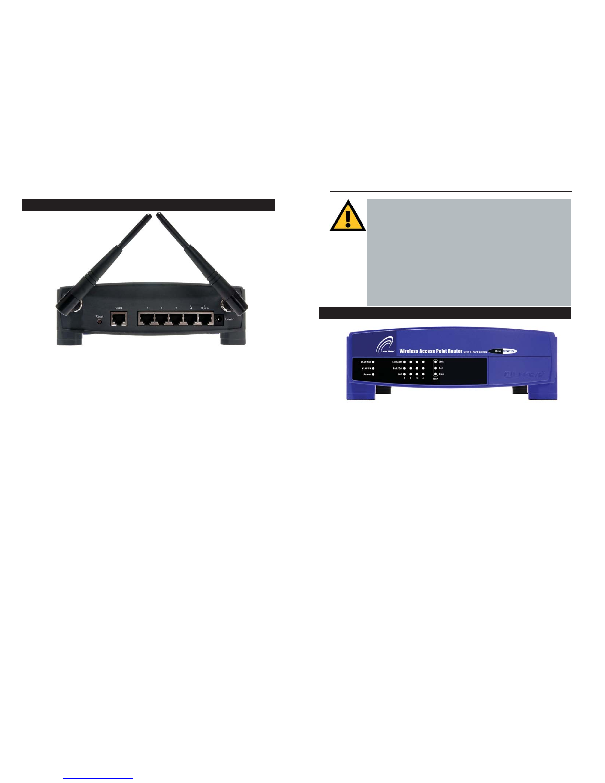
Figure 1-2
The Router’s rear panel (as shown in Figure 1-1) is where all of its connections
are made.
WA N The WAN (Wide Area Network) Port is where you will con-
nect your cable or DSL modem with an Ethernet cable. Your
modem connection will not work from any other port.
Ports 1-4 These four LAN (Local Area Network) ports are where you
will connect networked devices, such as PCs, print servers,
and any other Ethernet devices you want to put on your network. If Port 4 is being used, the Uplink Port will not work.
Uplink The Uplink Port is where you can expand your network by
connecting to another switch or hub. Uplinking to another
switch or a hub is done by simply running a cable from the
Uplink Port to the other device. The Uplink Port is shared
with Port 4. If the Uplink port is being used, Port 4 will not
work.
Power The Power Port is where you will connect the included AC
Power adapter.
Antenna Jacks The Antenna Jacks are where the included antennas are con-
nected.
Figure 1-1
The Wireless Access Point Router’s Ports
Instant Wireless®Series
Wireless Access Point Router with 4-Port Switch
5

Chapter 2: Connecting the Router
Before plugging everything together, it’s always a good idea to have everything
you’ll need to get the Router up and running. Depending upon how you conf igure the Router in Chapter 4: Configuring the Router, you may need some of the
following values from your ISP:
When connecting through a Static IP connection, be sure to have 1) Your
broadband-configured PC’s fixed Internet IP Address, 2) Your broadbandconfigured PC’s Computer Name and Workgroup Name, 3) Your Subnet
Mask, 4) Your Default Gateway, and 5) Your Primary DNS IP address.
When connecting through a PPPoE connection, be sure to have 1) Your
PPPoE User Name and 2) Your PPPoE Password.
The installation technician from your ISP should have left this information with
you after installing your broadband connection. If not, you can call your ISP to
request the data.
Once you have the above values, you can begin the Router’s installation and
setup.
Once you are sure that you have the above values on hand, you can begin the
Installation and Setup of the Router.
1. Power everything down, including your PCs, your cable or DSL modem and
the Router.
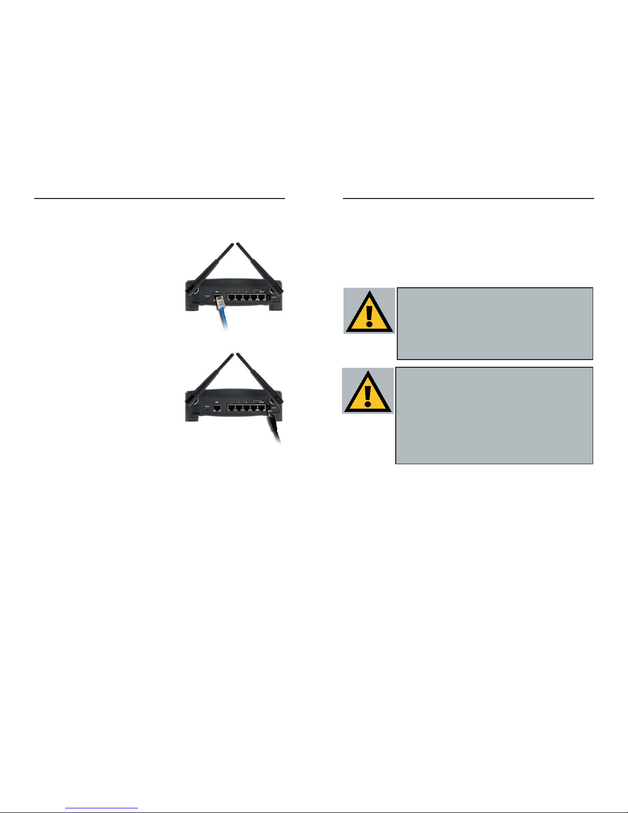
2. Connect an Ethernet cable from one of
your PC’s Ethernet ports to one of the
Router’s LAN ports (as shown in Figure 2-
1). Do the same with all the PCs you wish
to connect to the Router. (LAN Port 4 will
become inactive if you use the Uplink
port.)
Before You Start
Full/Col Green. This LED also serves two purposes. When this LED
is lit continuously, the connection made through the corresponding port is running in Full Duplex mode. A blinking
LED indicates that the connection is experiencing collisions.
Infrequent collisions are normal. If this LED blinks too
often, there may be a problem with your connection. Refer to
the Troubleshooting Appendix if you think there is a problem.
100 Orange. This LED indicates when a successful 100Mbps
connection is made through the corresponding port.
The WAN Indicators
Link Green. This LED indicates a connection between the Router
and your broadband device or network.
Act Green. This LED blinks when the Router is sending or
receiving data over the broadband (WAN) port.
Diag Red. This LED indicates the Router’s self-diagnosis mode
during boot-up and restart. It will turn off upon completing
the diagnosis. If this LED stays on for an abnormally long
period of time, refer to the Troubleshooting Appendix.
7
Connecting Your Hardware Together and Booting Up
Figure 2-1
Instant Wireless®Series
Wireless Access Point Router with 4-Port Switch
8
For Wireless Connections: In addition to accessing the Router through an
Ethernet connection, a wireless connection can be used to access the Router.
After powering on the Router and connecting it to your modem, enter the
Router’s IP Address in the Address field of your wireless PC’s web-browser as
follows: http://192.168.1.1 and press Enter.
IImmppoorrttaanntt::
The Wireless Access Point Router with 4-Port Switch is
configured by default to work out of the box with all Linksys Wireless
Adapters. If you have changed the defaults on your Linksys Wireless
Adapters, or are using other wireless adapters, you must temporarily change your wireless adapter settings to: (SSID = linksys) in
order to initially access the Router wirelessly. After you have
accessed the Router with the default settings, you can change the
router settings to coincide with your Network settings and reset your
adapters.
IImmppoorrttaanntt::
Some ISPs—most notably some cable providers—configure their networks so that you do not have to enter a full Internet
address into your web browser or e-mail application to reach your
home page or receive your e-mail. If your Internet home page
address is something very simple, such as “www”, rather than
“www.linksys.com”, or your e-mail server’s address is something similar to “e-mail” or “pop3”, rather than “pop.mail.linksys.com”, you
won’t be able to properly configure the Router until you determine the
actual Internet addresses of your Web and e-mail connections.
You
mmuusstt
obtain this information prior to connecting the Router to
your network. You can obtain this information by contacting your ISP.
10
In addition to accessing the Router through an Ethernet connection, a wireless connection can be used to access the Router. See the “For Wireless
Connections” section that follows these connection instructions.
3. Connect another Ethernet cable from your
cable or DSL modem to the Router’s WA N
port (as shown in Figure 2-2).
4. Connect the Power Adapter (included) to
the Router’s Power port (as shown in Figure
2-3) and plug the other end into a power
outlet.
• The Power LED will illuminate green
as soon as the power adapter is connected.
• The Diag LED will illuminate red for a
few seconds while the Router goes
through its internal diagnostic test. The
LED will turn off when the self-test is
complete.
5. Power on the cable or DSL modem. Verify that the power is on by checking
the Link LED in the WAN column on the front of the Router. The Link LED
will be illuminated if the power is on and the modem is ready.
6. Press the Reset button on the back of the Router. Hold the button in for three
seconds, or until the Diag LED illuminates red. This restores the Router’s
default settings.
7. Power on your PC.
The Router is now connected. Continue to the next chapter to configure
your PCs.
Figure 2-2
Figure 2-3
Instant Wireless®Series Wireless Access Point Router with 4-Port Switch
9
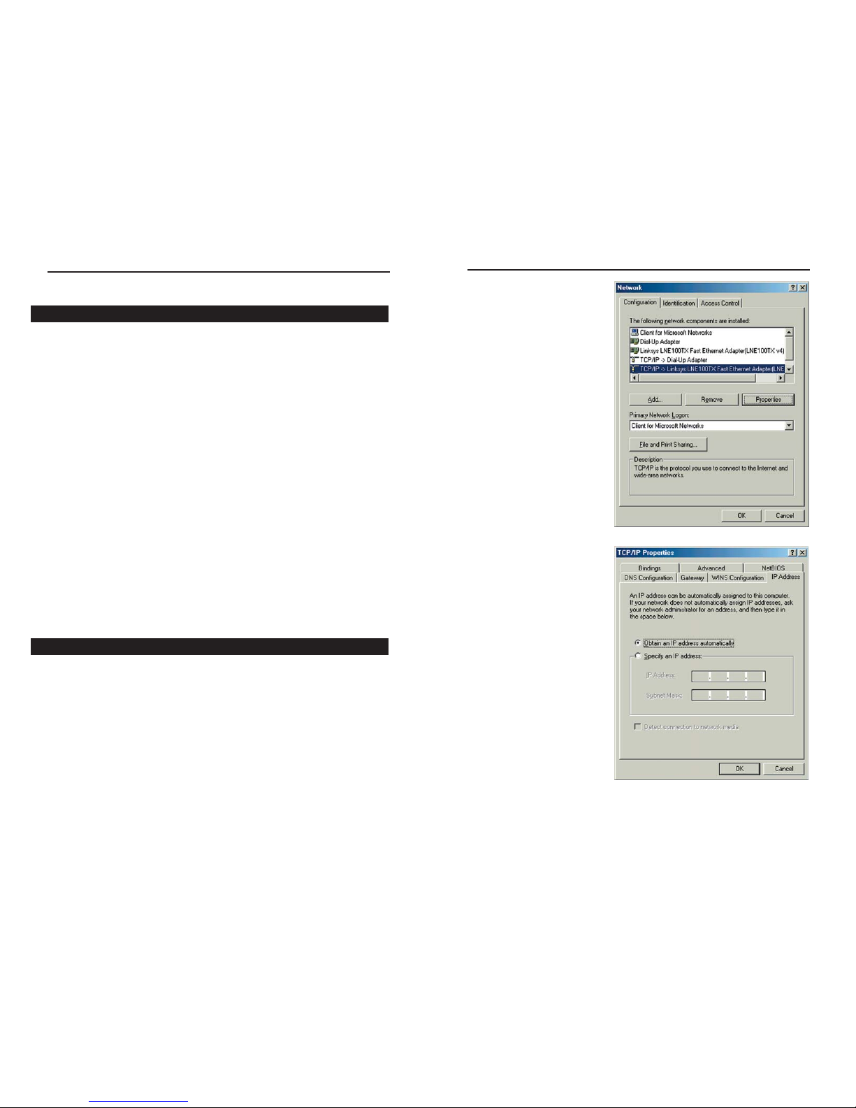
2. Select the Configuration tab
and highlight the TCP/IP
line for the applicable
Ethernet adapter (as shown
in Figure 3-1). If the word
TCP/IP appears by itself,
select that line. (Note: If
there is no TCP/IP line listed, refer to your Ethernet
adapter’s documentation to
install TCP/IP now.) Then,
click the Properties button.
3. Click the IP Address tab
and select Obtain an IP
address automatically (as
shown in figure 3-2).
4. Click the Gateway tab and verify that the Installed Gateway field is blank.
Click the OK button.
Chapter 3: Configuring the PCs
These instructions will help you configure each of your computers to communicate with the Router.
To do this, you will need to conf igure your PC’s network settings to obtain an
IP (or TCP/IP) address automatically. Computers use IP addresses to communicate with each other across a network or the Internet.
You will need to know which operating system your computer is running, such
as Windows 95, 98, Millennium, 2000, or XP. You can find out by clicking the
Start button and then selecting the Settings option. (If your Start menu doesn’t have a Settings option, you’re running Windows XP. You can select the
Control Panel directly from the Start Menu.) Then, click Control Panel and
double-click the System icon. Click the Cancel button when done.
Once you know which Windows operating system you are running, follow the
directions in this step for your computer’s operating system. If you PC is not
configured with the TCP/IP protocol, you will need to do this for each computer you are connecting to the Router.
The next few pages tell you, step by step, how to conf igure your TCP/IP settings based on the type of Windows operating system you are using. Once
you've configured your computers, continue to Chapter 4: Configuring the
Router.
1. Click the Start button, click Settings and open the Control Panel. From
there, double-click the Network icon to open the Network screen.
12
Overview
Configuring Windows 95, 98, and Millennium PCs
Figure 3-1
Figure 3-2
Instant Wireless®Series
Wireless Access Point Router with 4-Port Switch
11
5. Click the OK button again. Windows may ask you for the original
Windows installation disk or additional files. Supply them by pointing to
the correct file location, e.g., D:\win98, D:\win9x,
c:\windows\options\cabs, etc. (This assumes that “D” is the letter of your
CD-ROM drive).
6. If Windows asks you to restart your PC, click the Ye s button. If Windows
does not ask you to restart, restart your computer anyway.
Repeat steps 1-6 for each PC on your network. When all of your PCs are
configured, proceed to Chapter 4: Configuring the Router.
1. Click the Start button, click Settings and open the Control Panel. From
there, double-click the Network and Dial-up Connections icon. This will
display the Network screen.
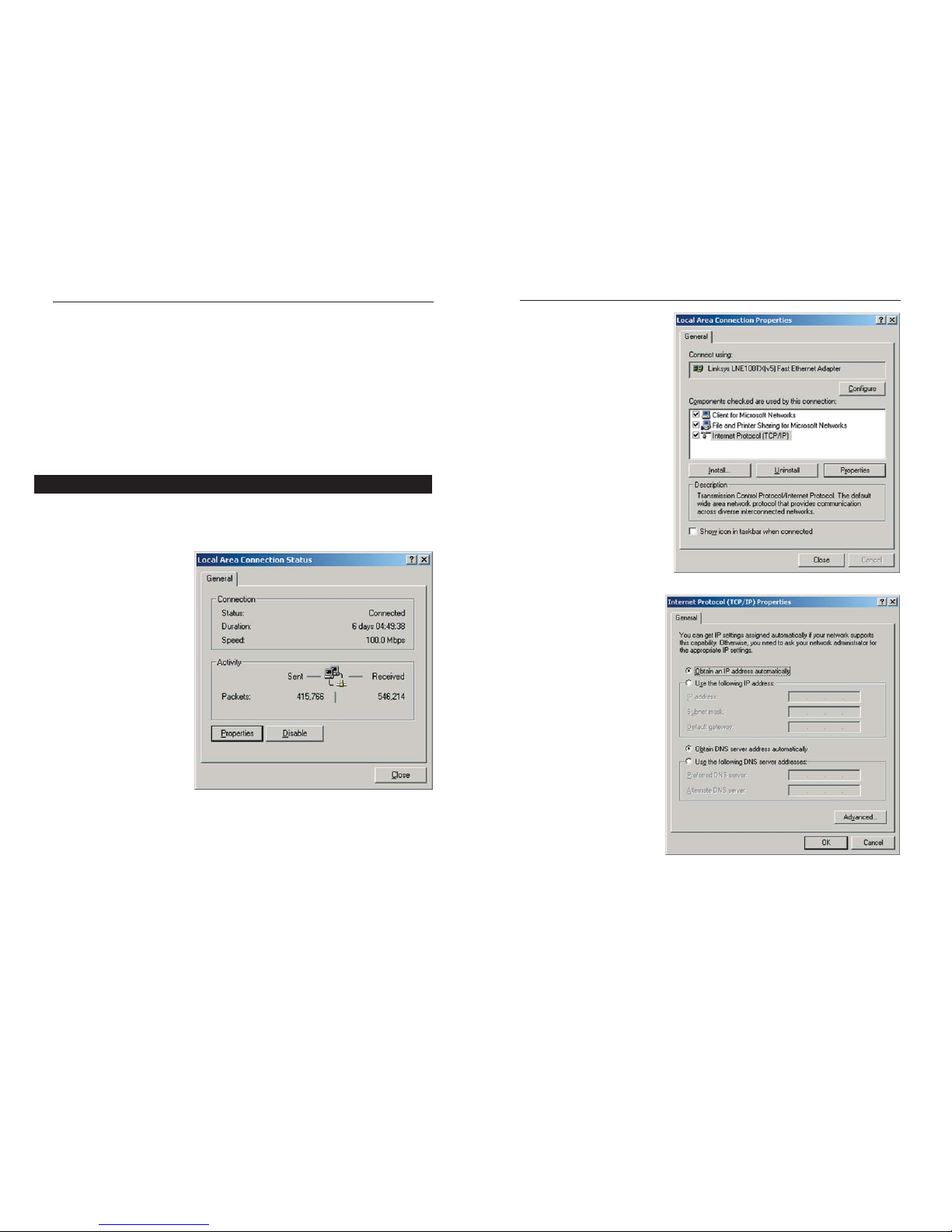
2. Select the Local Area
Connection icon for the
applicable Ethernet
adapter (usually it is the
first Local Area
Connection listed).
3. When the Local Area Connection Status screen appears, click the
Properties button. (See Figure 3-3.)
4. Select Internet Protocol
(TCP/IP) (as shown in
Figure 3-4) and click the
Properties button.
5. Select Obtain an IP
address automatically
and verify that Obtain
DNS server address
automatically is select-
ed (as shown in Figure
3-5). Then, click the OK
button and click the OK
button on the subsequent screens to complete the PC’s configuration.
Repeat steps 1-5 for each PC on your network. When all of your PCs are
configured, proceed to Chapter 4: Configuring the Router.
Configuring Windows 2000 PCs
Figure 3-3
Figure 3-4
Figure 3-5
Instant Wireless®Series
Wireless Access Point Router with 4-Port Switch
13 14
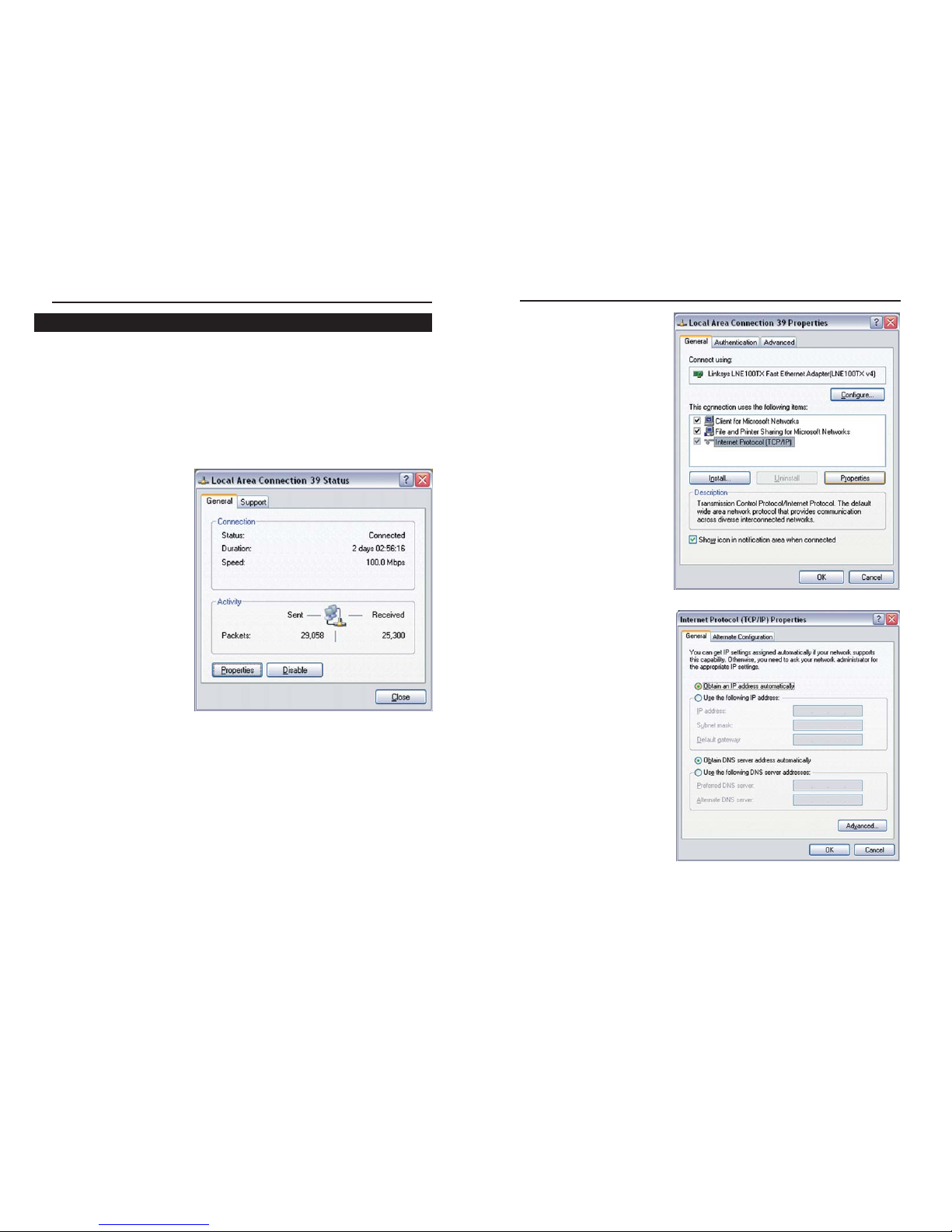
The following instructions assume you are running Windows XP’s default
interface. If you are using the Classic interface (where the icons and menus
look like previous Windows versions), please follow the instructions for
Windows 2000.
1. Click the Start button, open the Control Panel. and click the Network and
Internet Connections icon. Then, click the Network Connections icon to
display the Network screen.
2. Select the Local Area
Connection icon for
the applicable Ethernet
adapter (usually it is
the first Local Area
Connection listed).
3. When the Local Area Connection Status screen appears, click the
Properties button. (See Figure 3-6.)
4. Select Internet Protocol
(TCP/IP) (as shown in
Figure 3-7) and click the
Properties button.
5. Select Obtain an IP
address automatically
and verify that Obtain
DNS server address automatically is selected (as
shown in Figure 3-8).
Then, click the OK button
and click the OK button on
the subsequent screens to
complete the PC’s configuration.
Repeat steps 1-5 for each PC on your network. When all of your PCs are
configured, proceed to Chapter 4: Configuring the Router.
Configuring Windows XP PCs
Figure 3-6
Figure 3-7
Figure 3-8
Instant Wireless®Series
Wireless Access Point Router with 4-Port Switch
15 16
3. If required by your ISP, enter the Router’s Host Name and Domain Name
in the appropriate fields on the Setup tab. (This is usually required by cable
ISPs.)
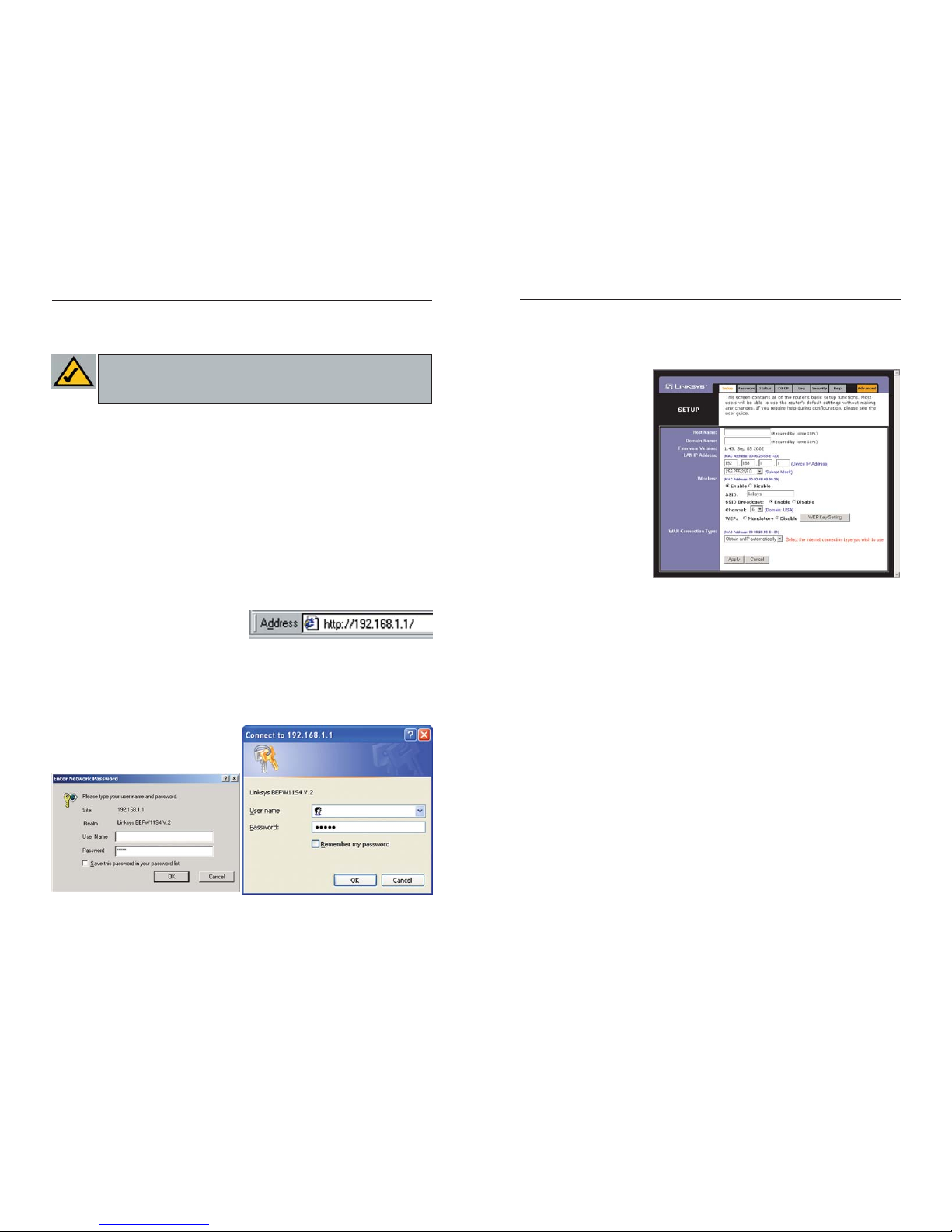
4. To conf igure the
Router for your wireless network, verify
that the Setup tab’s
Wireless fields (shown
in Figure 4-3) are
completed as follows:
Enable/Disable:
Selecting the Enable
radio button will
enable the Router’s
wireless feature.
Wireless functions
will not be available
unless enabled.
SSID: The SSID is a unique name for your wireless network. It is case sensitive and must not exceed 32 characters. The default SSID is "linksys " but
you should change this to a personal wireless network name. All wireless
points in your network must use the same SSID.
SSID Broadcast - Allows the SSID to be broadcast on your network. You
may want to enable this function while conf iguring the Router, but make
sure that you disable it when you are finished. With this enabled, someone
could easily obtain the SSID information with site survey software and gain
unauthorized access to your network. Click Enable to broadcast. Click
Disable to increase network security and prevent the SSID from being seen
on networked PCs.
Channel: Select the appropriate channel for your network from the list provided. All wireless points in your network must use the same channel in
order to function properly.
Do not change the WEP setting from the default, “Disabled”, without first
referring to the Wireless Security sections of the User Guide or Setup
Wizard CD-ROM for advanced features and settings.
17 18
Chapter 4: Configuring the Router
This chapter will show you how to conf igure the Router to function in your network and gain access to the Internet through your Internet Service Provider
(ISP). Detailed description of the Router’s Web-based Utility can be found in
the Chapter 5: Using the Router’s Web-Based Utility. Your ISP may require the
use of a Host Name and Domain Name. Further, you will set the WAN
Configuration Type on the Router’s Setup tab from the information given by
your ISP. You will need this setup information from your ISP. If you do not have
this information, please contact your ISP before proceeding.
The instructions from your ISP tell you how to set up your PC for Internet
access. Since you are now using the Router to share Internet access among several computers, you will use this setup information for Router configuration.
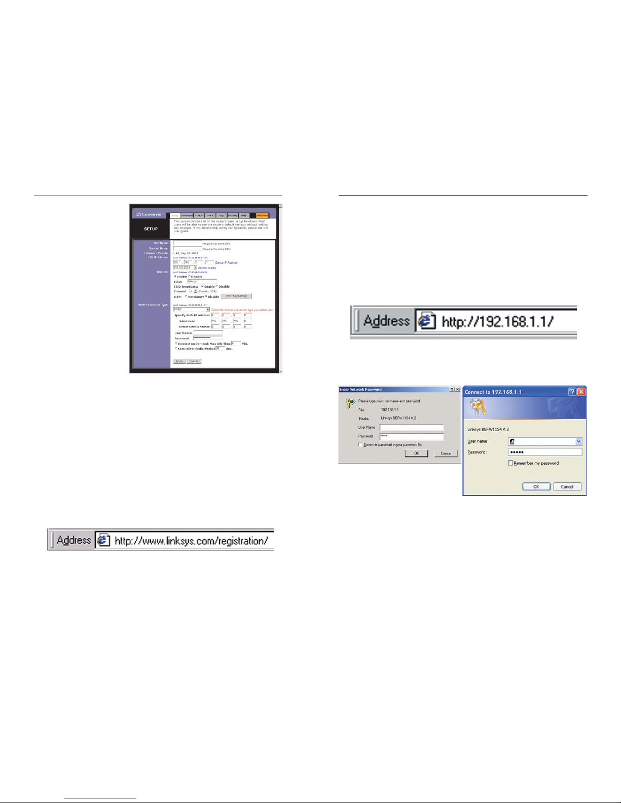
1. Open your web browser, and enter
192.168.1.1 into the web browser’s
Address field, as shown in Figure 4-
1. Then, press the Enter key.
2. An Enter Network Password window, shown in Figure 4-2a, will appear.
(Windows XP users will see a Connect to 192.168.1.1 window, shown in
Figure 4-2b.) Leave the User Name f ield empty, and enter admin (the
default password) in lowercase letters in the Password field. Then,
click the OK button.
Figure 4-1
Figure 4-2a Figure 4-2b
Figure 4-3
Instant Wireless®Series
Wireless Access Point Router with 4-Port Switch
Note: Linksys recommends using the Setup Wizard CD for first time
installation of the Router and for setting up additional computers. For
additional assistance, follow the steps in this chapter.
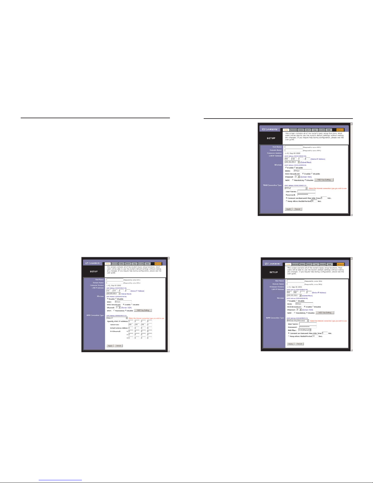
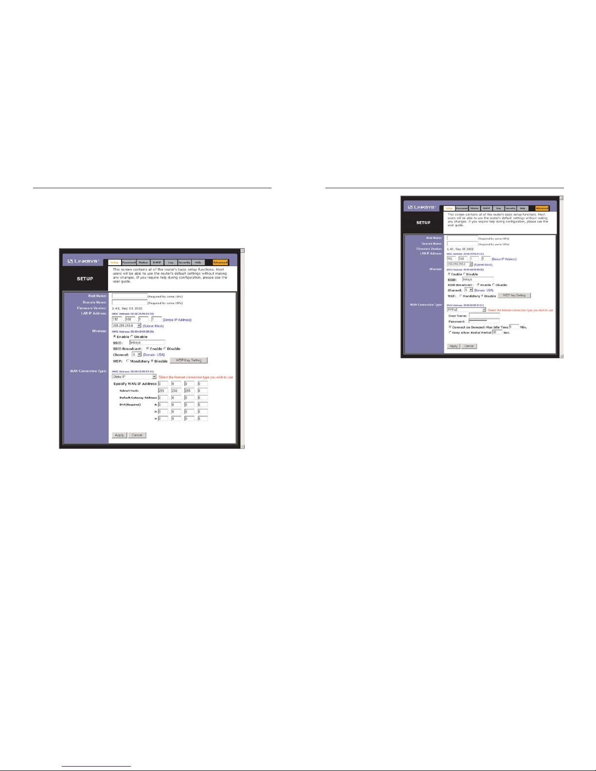
PPPoE
If your DSL provider
says that you are connecting through PPPoE
or if you normally enter
a user name and password to access the
Internet, perform these
steps (shown in Figure
4-5):
a. Select PPPoE as the
WAN Connection
Type.
b. Enter the User
Name.
c. Enter the Password.
d. Click the Apply button to save the settings.
RAS (for SingTel Users)
RAS is a service used in
Singapore only. If you are
using a RAS connection
(as shown in Figure 4-6),
check with your ISP for
the necessary setup information.
19 20
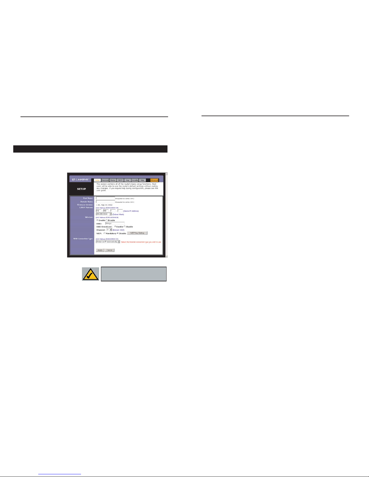
5. The Router supports five connection types: DHCP (obtain an IP automatically), PPPoE, Static IP Address, RAS, and PPTP. These types are selected
from the drop-down menu beside WAN Connection Type. The Setup tab
and available features will differ depending on what kind of connection type
you select, the instructions for which are included here:
Obtain an IP Automatically
If your ISP says that you are connecting through a dynamic IP address (or
DHCP), perform these steps:
a. Select Obtain an IP automatically as the WAN Connection Type (as
previously shown in Figure 4-3).
b. Click the Apply button to save the settings.
Static IP
If your ISP says that you are connecting through a static (or fixed) IP
address, perform these steps (as shown in Figure 4-4):
a. Select Static IP as the WAN Connection Type.
b. In the fields beside
“Specify WAN IP
Address”, enter the IP
Address.
c. Enter the Subnet Mask.
d. Enter the Default
Gateway Address.
e. Enter the DNS in the 1,
2, and/or 3 fields. You
must enter at least one
DNS address.
f. Click the Apply button
to save the settings.
Figure 4-4
Figure 4-5
Figure 4-6
Instant Wireless®Series
Wireless Access Point Router with 4-Port Switch
Chapter 5: Using the Router’s WebBased Utility
For your convenience, an administrative utility has been programmed into the
Router. This chapter will explain all of the functions in this utility. All routerbased administrative tasks are performed through this web utility. The web utility can be accessed by any PC on the network by typing “http://192.168.1.1” in
the PC’s web browser address window, as shown in Figure 5-1.
Upon entering the address into the web browser, a password request page will
pop up, as shown in Figure 5-2a. (Windows XP users will see a “Connect to
192.168.1.1” window, shown in Figure 5-2b.)
Leave the User Name field empty, and enter admin (the default password) in
lowercase letters in the Password field. Then, click the OK button.
In this chapter, you will find brief descriptions of each of the utility’s tabs and
its more important functions. More detailed explanations and instructions can
be found by clicking each page’s Help button or on Linksys’s website at
www.linksys.com. To clear any values you’ve entered on any page, click the
Cancel button. To apply any settings you’ve altered on any page, click the
Apply button.
21
PPTP
PPTP is a service used in
Europe only. If you are
using a PPTP connection
(as shown in Figure 4-7),
check with your ISP for
the necessary setup information.
6. If you haven’t already done so, click the Apply button to save the settings.
7. Reset the power on your cable or DSL modem and restart your computers.
They will now obtain the Router's new settings.
Note: You only need to configure the Router from one computer. If you
need advanced setting information, please refer to the Linksys support website at support.linksys.com or the User Guide on the Setup Wizard CDROM.
Congratulations! You’ve successfully configured the Router. You can test
the setup by opening your web browser from any computer and entering
www.linksys.com/registration (as shown in Figure 4-8).
If you are unable to reach our website, you may want to review what you
did in this section or refer to the Troubleshooting Appendix.
Figure 4-7
Figure 4-8
Figure 5-1
Figure 5-2a
Figure 5-2b
Instant Wireless®Series
Wireless Access Point Router with 4-Port Switch
22
• SSID: The SSID is a unique name for your wireless network. It is case sensitive and must not exceed 32 characters. The default SSID is "linksys " but you
should change this to a personal wireless network name. All wireless points
in your network must use the same SSID. Verify that you are using the correct
SSID and click the Apply button to set it.
• SSID Broadcast - Allows the SSID to be broadcast on your network. You may
want to enable this function while configuring the Router, but make sure that
you disable it when you are finished. With this enabled, someone could easily
obtain the SSID information with site survey software and gain unauthorized
access to your network. Click Enable to broadcast. Click Disable to increase
network security and prevent the SSID from being seen on networked PCs.
• Channel Select the appropriate channel from the list provided to correspond
with your network settings, between 1 and 11. (Higher channels can only be
used outside of the United States and Canada.) All points in your wireless network must use the same channel in order to function correctly. Verify that the
correct channel is selected and click the Apply button to set it.
• WEP (Mandatory/Disable). In order to utilize WEP encryption, select
Enable. If you do not wish to utilize WEP encryption, make sure Disable is
selected.
• WEP Key Setting When WEP Encryption is Enabled, press this button to
modify the WEP Key Settings.
For further details on configuring Wireless Security, using WEP, refer to
Appendix C: Configuring Wireless Security.
• WAN Connection Type The Router supports five connection types: DHCP
(obtain an IP automatically), PPPoE, Static IP Address, RAS, and PPTP. These
types are selected from the drop-down menu beside WAN Connection Type.
The Setup tab and available features will differ depending on what kind of
connection type you select. Each option is described on the following pages.
Obtain an IP Automatically
If your ISP says that you are connecting through a dynamic IP address (or
DHCP), select this option from the drop-down menu (as shown in Figure 5-3).
Now, the Router will accept the dynamic IP addresses assigned by your ISP
when connecting to the Internet.
23 24
The utility’s tabs: Setup, Password, Status, DHCP, Log, Security and Help are
used for Basic Setup of the Router. When the Advanced Tab is clicked, further
options will be displayed for Filters, Forwarding, Dynamic Routing, Static
Routing DMZ Host, MAC Address Cloning, and Wireless configuration.
The Setup tab is the first tab you will see when you access the Utility. If you
have already installed and set up the Router, you have already seen this tab and
have already properly configured all of the values.
• Host Name This
entry is necessary
for some ISPs and
can be provided by
them.
• Domain Name
This entry is necessary for some ISPs
and can be provided
by them.
• Firmware Version
This displays the
firmware version
the Router is currently using. As future versions of the Router’s
firmware become available,
they can be downloaded from the Linksys website at www.linksys.com.
• LAN IP Address and Subnet Mask This is the Router’s IP Address and
Subnet Mask as seen on the internal LAN. The default value is 192.168.1.1
for IP Address and 255.255.255.0 for Subnet Mask.
• Wireless (Enable/Disable). In order to utilize the Router’s wireless func-
tions, select Enable. If you do not wish to utilize any wireless functions,
make sure Disable is selected. (Note: No other wireless functions will be
available unless you enable this setting.)
Setup
Figure 5-3
NNoottee::
Due to differences in web
browsers, some screen shots may differ.
Instant Wireless®Series
Wireless Access Point Router with 4-Port Switch
25
PPPoE
Some DSL-based
ISPs use PPPoE
(Point-to-Point
Protocol over
Ethernet) to establish communications with an enduser. If you are
using a DSL line,
check with your ISP
to see if they use
PPPoE. If they do
use PPPoE, select
this from the dropdown menu (as
shown in Figure 5-
5).
If you do enable PPPoE, remember to remove any existing PPPoE applications already on any of your PCs.
• User Name and Password Enter the User Name and Password you use
when logging onto your ISP connection.
• Connect on Demand and Max Idle Time You can conf igure the Router
to disconnect your ISP connection after a specified period of time (Max
Idle Time). If you have been disconnected due to inactivity, Connect on
Demand enables the Router to automatically re-establish your connection as
soon as you attempt to access the Internet again. If you wish to activate
Connect on Demand, click the radio button. If you want your Internet connection to remain on at all times, enter 0 in the Max Idle Time field.
Otherwise, enter the number of minutes you want to have elapsed before
your Internet access disconnects.
• Keep Alive Option and Redial Period This option keeps you connected to
your ISP indefinitely, even when your connection sits idle. To use this
option, click the radio button next to Keep Alive. The default Redial Period
is 30 seconds.
26
Static IP
If your ISP says that you are connecting through a static (or fixed) IP
address, select this option from the drop-down menu (as shown in Figure 5-
4). The Router will utilize that static IP Address when the following information is entered into the appropriate field:
• WAN IP Address and Subnet Mask This is the Router’s IP Address and
Subnet Mask as seen by external users on the Internet (including your
ISP).
• Default Gateway Address Your ISP will provide you with the Gateway
IP Address.
• DNS (Domain Name Server) IP Address Your ISP will provide you
with at least one DNS IP Address.
Figure 5-4
Figure 5-5
Instant Wireless®Series
Wireless Access Point Router with 4-Port Switch
28
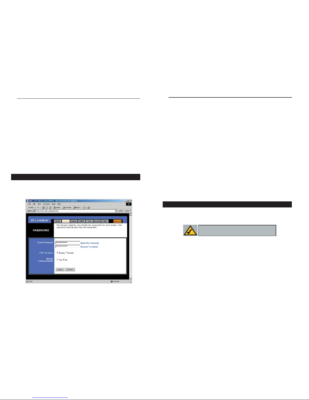
• Router Password For greater security, you should set a password for the
Router. If you don’t set the password, all users on your network will be able
to access the Router using the default password admin. We recommend that
you change your password often.
• UPnP Services Universal Plug and Play (UPnP) allows systems, such as
Windows XP PCs to automatically conf igure the Router for various Internet
applications, such as gaming and videoconferencing. Click the radio button
next to Enable to enable UPnP Services, or Disable to disable UPnP
Services.
• Restore Factory Defaults If you select the Restore Factory Default option
and click the Apply button, you will clear all of the Router’s settings and
restore the default settings.
Do not restore the factory defaults unless you are having difficulties with the
Router and have exhausted all other troubleshooting measures. Once the Router
is reset, you will have to re-enter all of your configuration data.
To clear any values you’ve entered on any page, click the Cancel button. To
apply any settings you’ve altered on any page, click the Apply button.
The Status tab, shown in Figure 5-8, displays the Router’s current status; it
reflects the data and selections you’ve entered using the Setup tab and provides
options for DHCP users.
All of the information provided on the Status tab is read-only and can be
changed using the Setup tab.
• Host Name This field shows the name of the Router. This entry is necessary for some ISPs.
• Firmware Version This field shows the installed version and date of the
firmware. Version dates are slightly more accurate than version numbers.
• Login This indicates if you are using a dial-up style connection like
PPPoE, RAS, or PPTP. For PPPoE, RAS, or PPTP only, there is a Connect
button to click if you are disconnected and want to re-establish a connection.
RAS (for SingTel Users)
RAS is a service used in Singapore only. If you are using a RAS connection
(as shown in Figure 4-6), check with your ISP for the necessary setup information.
PPTP
PPTP is a service used in Europe only. If you are using a PPTP connection
(as shown in Figure 4-7), check with your ISP for the necessary setup information.
You can confirm that the above settings are correct by successfully connecting
to the Internet.
To clear any values you’ve entered on any page, click the Cancel button. To
apply any settings you’ve altered on any page, click the Apply button.
From the Password tab, shown in Figure 5-7, you can change the Router’s
Password, enable Universal Plug and Play (UPnP) Services for systems such as
Windows XP PCs, and restore the Router’s factory default settings.
Password
Figure 5-7
Status
Note: The information provided on the Status
tab may vary depending on the Router’s settings.
Instant Wireless®Series
Wireless Access Point Router with 4-Port Switch
27
 Loading...