

Page 1

D-Link ™ DES-3028/DES-3028P/DES-3052/DES-3052P
Managed 10/100Mbps Fast Ethernet Switch
Release I
CLI Reference Manual
Page 2

_________________________________________________________________________________
Information in this document is subject to change without notice.
© 2007 D-Link Corporation. All rights reserved.
Reproduction in any manner whatsoever without the written permission of D-Link Computer Corporation is strictly forbidden.
Trademarks used in this text: D-Link and the D-LINK logo are trademarks of D-Link Computer Corporation; Microsoft and
Windows are registered trademarks of Microsoft Corporation.
Other trademarks and trade names may be used in this document to refer to either the entities claiming the marks and names or
their products. D-Link Computer Corporation disclaims any proprietary interest in trademarks and trade names other than its
own.
March 2007 P/N 651ES3052015G
Page 3

Table of Contents
CLI REFERENCE MANUAL .........................................................................................................................................I
INTRODUCTION ..........................................................................................................................................................1
USING THE CONSOLE CLI.........................................................................................................................................4
COMMAND SYNTAX ...................................................................................................................................................8
BASIC SWITCH COMMANDS...................................................................................................................................10
MODIFY BANNER AND PROMPT COMMANDS .....................................................................................................20
SWITCH PORT COMMANDS ....................................................................................................................................23
PORT SECURITY COMMANDS ................................................................................................................................26
NETWORK MANAGEMENT (SNMP) COMMANDS .................................................................................................30
SWITCH UTILITY COMMANDS ................................................................................................................................49
NETWORK MONITORING COMMANDS ..................................................................................................................57
MULTIPLE SPANNING TREE PROTOCOL (MSTP) COMMANDS .........................................................................69
FORWARDING DATABASE COMMANDS...............................................................................................................81
BROADCAST STORM CONTROL COMMANDS .....................................................................................................87
COS COMMANDS......................................................................................................................................................91
PORT MIRRORING COMMANDS ...........................................................................................................................105
VLAN COMMANDS .................................................................................................................................................108
LINK AGGREGATION COMMANDS.......................................................................................................................113
BASIC IP COMMANDS............................................................................................................................................118
IGMP SNOOPING COMMANDS..............................................................................................................................121
DHCP RELAY...........................................................................................................................................................128
802.1X COMMANDS................................................................................................................................................133
Page 4

ACCESS CONTROL LIST (ACL) COMMANDS......................................................................................................151
TIME RANGE COMMANDS.....................................................................................................................................164
SAFEGUARD ENGINE COMMANDS......................................................................................................................166
TRAFFIC SEGMENTATION COMMANDS..............................................................................................................168
TIME AND SNTP COMMANDS ...............................................................................................................................170
ARP COMMANDS....................................................................................................................................................176
ROUTING TABLE COMMANDS..............................................................................................................................180
MAC NOTIFICATION COMMANDS ........................................................................................................................182
ACCESS AUTHENTICATION CONTROL COMMANDS ........................................................................................185
SSH COMMANDS....................................................................................................................................................206
SSL COMMANDS ....................................................................................................................................................213
D-LINK SINGLE IP MANAGEMENT COMMANDS.................................................................................................219
SMTP COMMANDS .................................................................................................................................................229
POE COMMANDS....................................................................................................................................................233
COMMAND HISTORY LIST.....................................................................................................................................237
TECHNICAL SPECIFICATIONS..............................................................................................................................241
Page 5
DES-3028 DES-3028P DES-3052 DES-3052P Layer 2 Fast Ethernet Switch CLI Reference Manual
1
INTRODUCTION
The Switch can be managed through the Switch’s serial port, Telnet, or the Web-based management agent. The Command Line
Interface (CLI) can be used to configure and manage the Switch via the serial port or Telnet interfaces.
This manual provides a reference for all of the commands contained in the CLI. Configuration and management of the Switch via
the Web-based management agent is discussed in the Manual. This manual provides a reference for all of the commands contained
in the CLI for members of this series, including the DES-3028, DES-3028P, DES-3052, and DES-3052P. Examples present in this
manual may refer to any member of this series and may show different port counts, but are universal to this series of switches,
unless otherwise stated. Configuration and management of the Switch via the Web-based management agent is discussed in the
User’s Guide.
Accessing the Switch via the Serial Port
The Switch’s serial port’s default settings are as follows:
• 9600 baud
• no parity
• 8 data bits
• 1 stop bit
A computer running a terminal emulation program capable of emulating a VT-100 terminal and a serial port configured as above
is then connected to the Switch’s serial port via an RS-232 DB-9 cable.
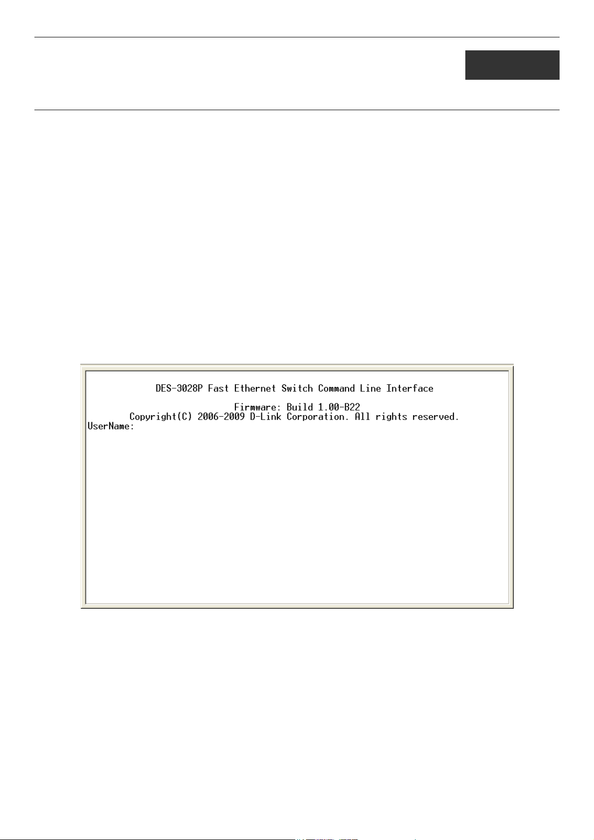
With the serial port properly connected to a management computer, the following screen should be visible. If this screen does not
appear, try pressing Ctrl+r to refresh the console screen.
Figure 1-1. Initial CLI screen
There is no initial username or password. Just press the Enter key twice to display the CLI input cursor − DES-3028P:4#. This is
the command line where all commands are input.
1
Page 6
DES-3028 DES-3028P DES-3052 DES-3052P Layer 2 Fast Ethernet Switch CLI Reference Manual
Setting the Switch’s IP Address
Each Switch must be assigned its own IP Address, which is used for communication with an SNMP network manager or other
TCP/IP application (for example BOOTP, TFTP). The Switch’s default IP address is 10.90.90.90. Users can change the default
Switch IP address to meet the specification of your networking address scheme.
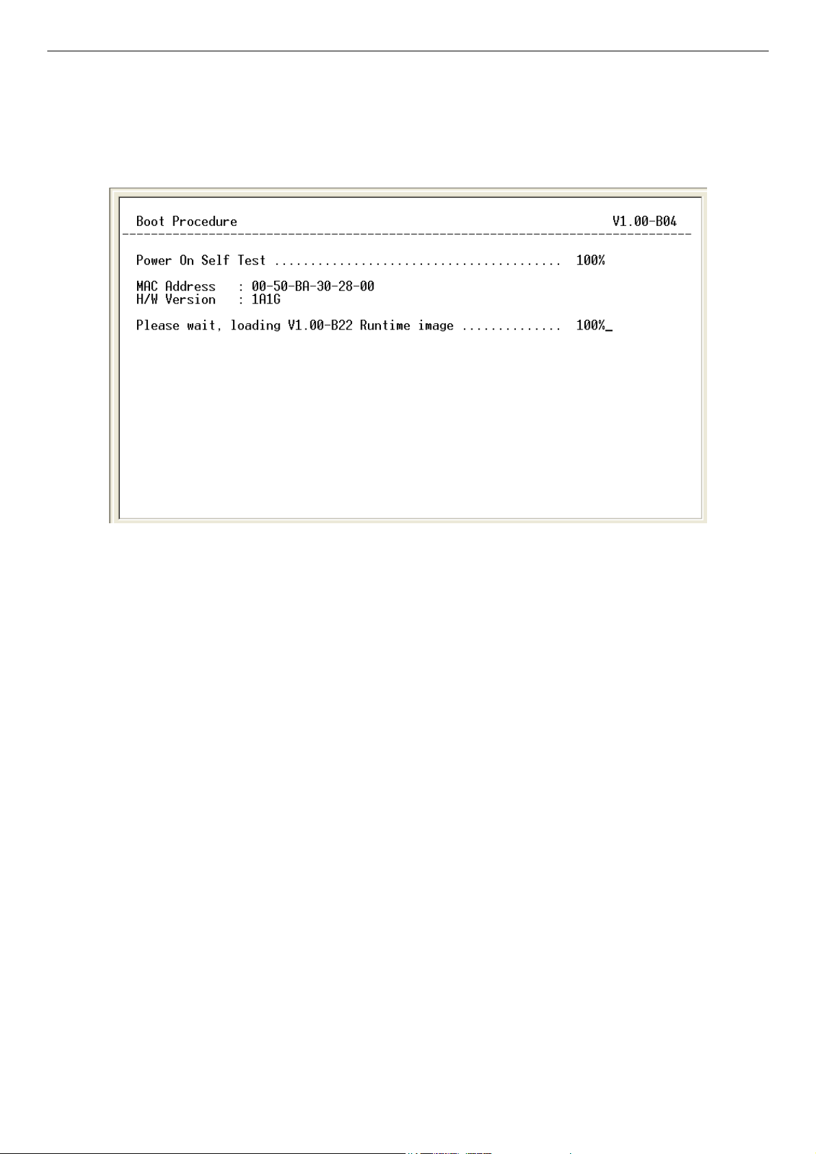
The Switch is also assigned a unique MAC address by the factory. This MAC address cannot be changed, and can be found on the
initial boot console screen – shown below.
Figure 1-2. Boot screen
The Switch’s MAC address can also be found in the Web management program on the Switch Information (Basic Settings)
window on the Configuration menu.
The IP address for the Switch must be set before it can be managed with the Web-based manager. The Switch IP address can be
automatically set using BOOTP or DHCP protocols, in which case the actual address assigned to the Switch must be known.
The IP address may be set using the Command Line Interface (CLI) over the console serial port as follows:
1. Starting at the command line prompt, enter the commands config ipif System ipaddress
xxx.xxx.xxx.xxx/yyy.yyy.yyy.yyy. Where the x’s represent the IP address to be assigned to the IP interface named
System and the y’s represent the corresponding subnet mask.
2. Alternatively, users can enter config ipif System ipaddress xxx.xxx.xxx.xxx/z. Where the x’s represent the IP address to
be assigned to the IP interface named System and the z represents the corresponding number of subnets in CIDR
notation.
The IP interface named System on the Switch can be assigned an IP address and subnet mask which can then be used to connect a
management station to the Switch’s Telnet or Web-based management agent.
2
Page 7
DES-3028 DES-3028P DES-3052 DES-3052P Layer 2 Fast Ethernet Switch CLI Reference Manual
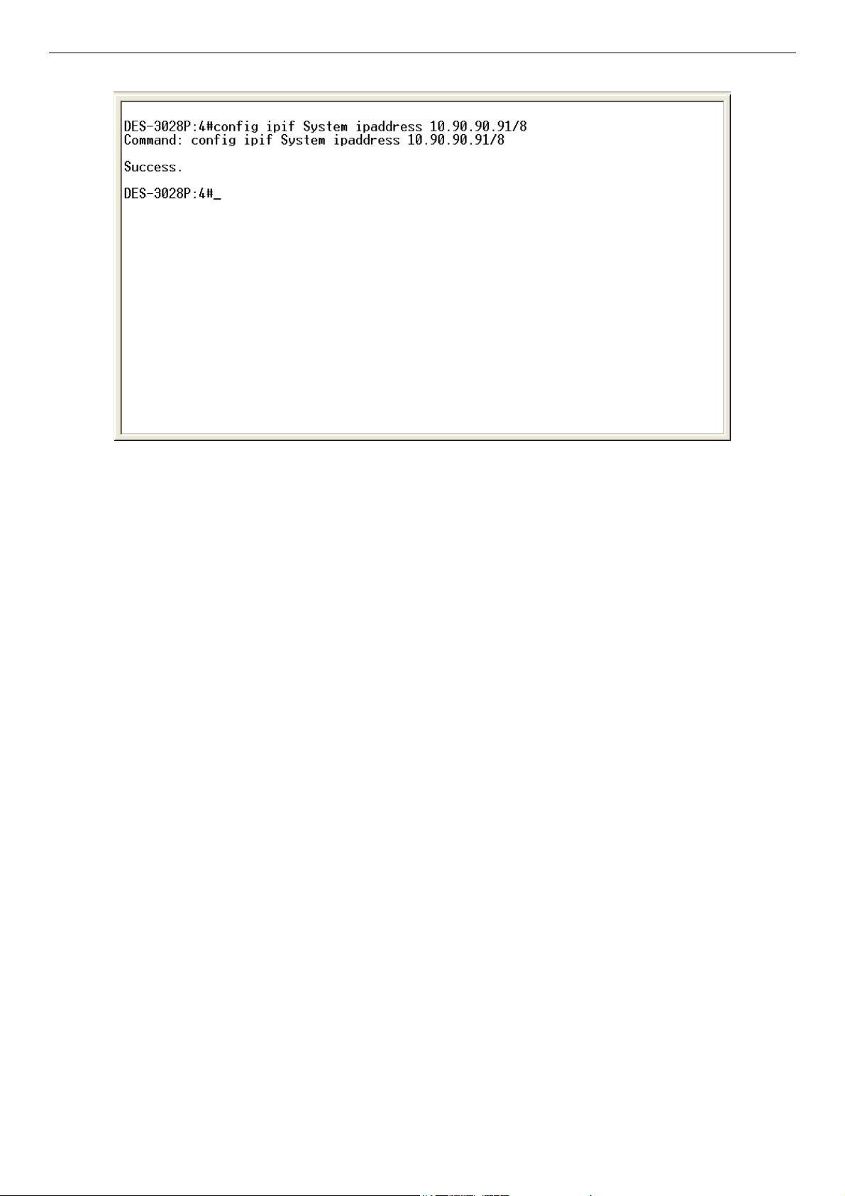
Figure 1-3. Assigning an IP Address
In the above example, the Switch was assigned an IP address of 10.90.90.91 with a subnet mask of 255.0.0.0. The system message
Success indicates that the command was executed successfully. The Switch can now be configured and managed via Telnet,
SNMP MIB browser and the CLI or via the Web-based management agent using the above IP address to connect to the Switch.
3
Page 8
DES-3028 DES-3028P DES-3052 DES-3052P Layer 2 Fast Ethernet Switch CLI Reference Manual
2
USING THE CONSOLE CLI
The DES-3028/28P/52/52P support a console management interface that allows the user to connect to the Switch’s management
agent via a serial port and a terminal or a computer running a terminal emulation program. The console can also be used over the
network using the TCP/IP Telnet protocol. The console program can be used to configure the Switch to use an SNMP-based
network management software over the network.
This chapter describes how to use the console interface to access the Switch, change its settings, and monitor its operation.
Note: Switch configuration settings are saved to non-volatile RAM using the save command. The current
configuration will then be retained in the Switch’s NV-RAM, and reloaded when the Switch is rebooted. If
the Switch is rebooted without using the save command, the last configuration saved to NV-RAM will be
loaded.
Connecting to the Switch
The console interface is used by connecting the Switch to a VT100-compatible terminal or a computer running an ordinary
terminal emulator program (e.g., the HyperTerminal program included with the Windows operating system) using an RS-232C
serial cable. Your terminal parameters will need to be set to:
• VT-100 compatible
• 9600 baud
• 8 data bits
• No parity
• One stop bit
• No flow control
Users can also access the same functions over a Telnet interface. Once users have set an IP address for your Switch, users can use
a Telnet program (in VT-100 compatible terminal mode) to access and control the Switch. All of the screens are identical, whether
accessed from the console port or from a Telnet interface.
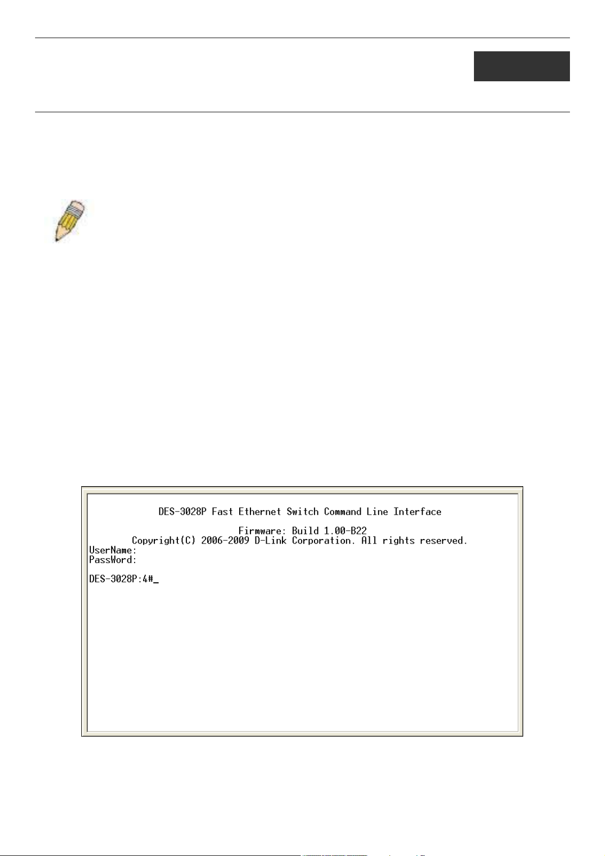
After the Switch reboots and users have logged in, the console looks like this:
Figure 2-1. Initial Console Screen after logging in
Commands are entered at the command prompt, DES-3028P:4#.
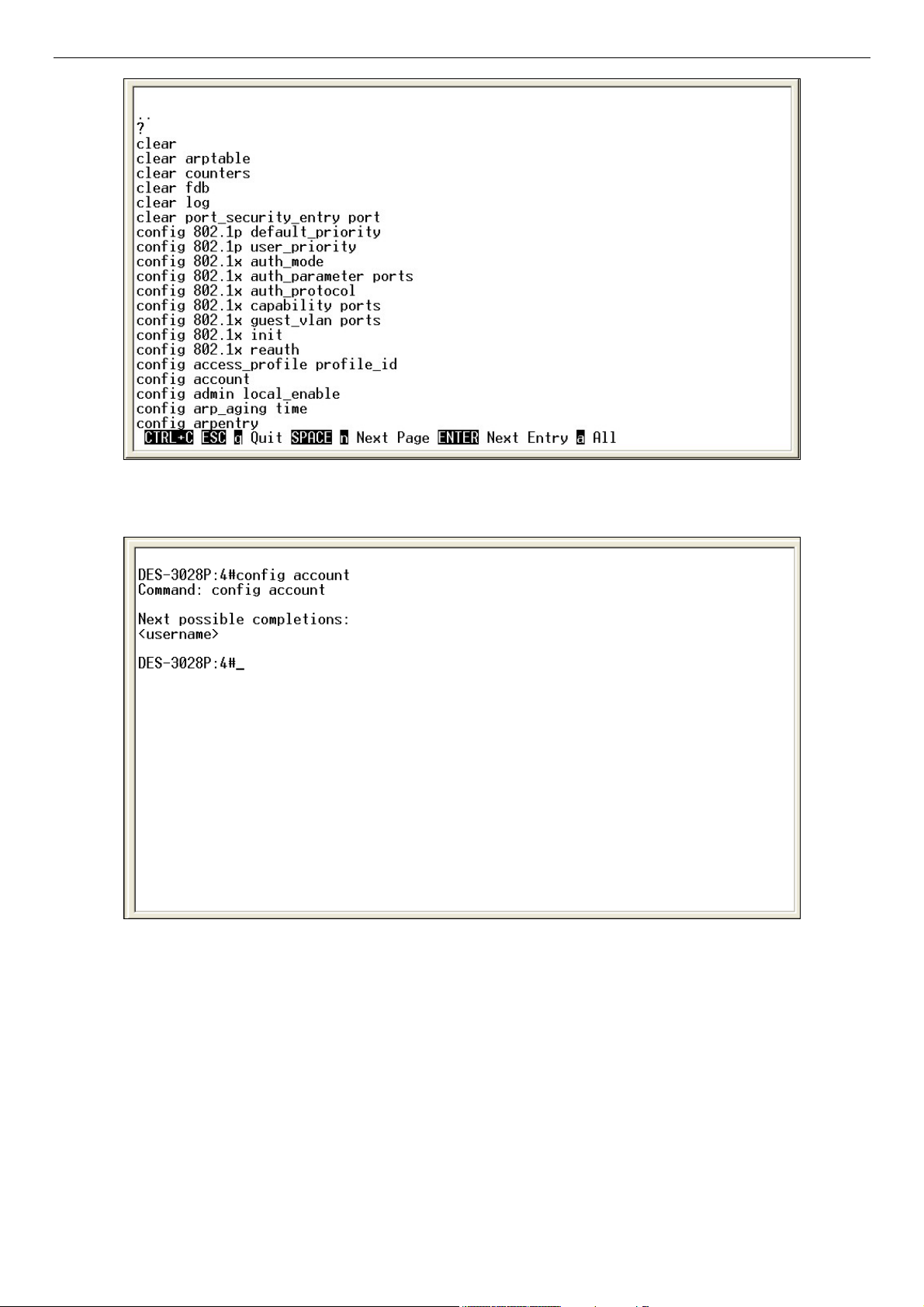
There are a number of helpful features included in the CLI. Entering the ? command will display a list of all of the top-level
commands.
4
Page 9
DES-3028 DES-3028P DES-3052 DES-3052P Layer 2 Fast Ethernet Switch CLI Reference Manual
Figure 2-2. The ? Command
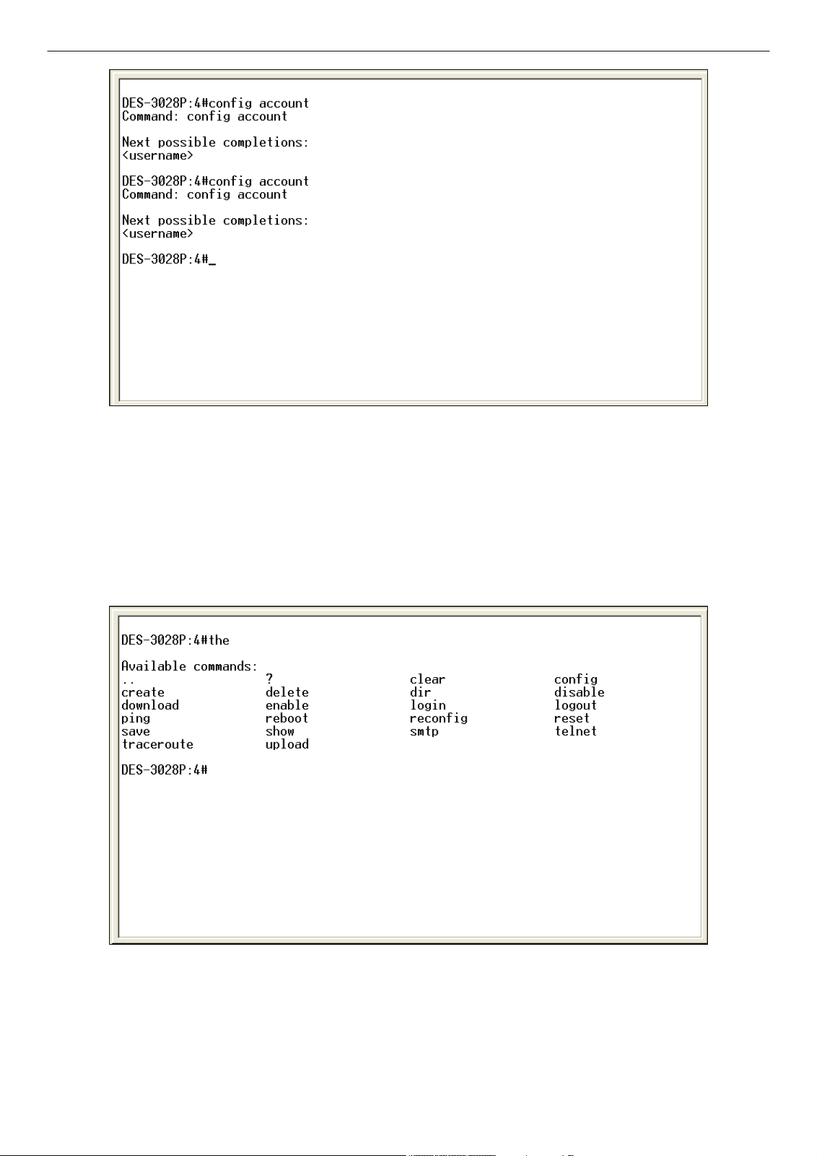
When users enter a command without its required parameters, the CLI will prompt users with a Next possible completions:
message.
Figure 2-3. Example Command Parameter Help
In this case, the command config account was entered with the parameter <username>. The CLI will then prompt users to enter
the <username> with the message, Next possible completions:. Every command in the CLI has this feature, and complex
commands have several layers of parameter prompting.
In addition, after typing any given command plus one space, users can see all of the next possible sub-commands, in sequential
order, by repeatedly pressing the Tab key.
To re-enter the previous command at the command prompt, press the up arrow cursor key. The previous command will appear at
the command prompt.
5
Page 10
DES-3028 DES-3028P DES-3052 DES-3052P Layer 2 Fast Ethernet Switch CLI Reference Manual
Figure 2-4. Using the Up Arrow to Re-enter a Command
In the above example, the command config account was entered without the required parameter <username>, the CLI returned
the Next possible completions: <username> prompt. The up arrow cursor control key was pressed to re-enter the previous
command (config account) at the command prompt. Now the appropriate username can be entered and the config account
command re-executed.
All commands in the CLI function in this way. In addition, the syntax of the help prompts are the same as presented in this manual
− angle brackets < > indicate a numerical value or character string, braces { } indicate optional parameters or a choice of
parameters, and brackets [ ] indicate required parameters.
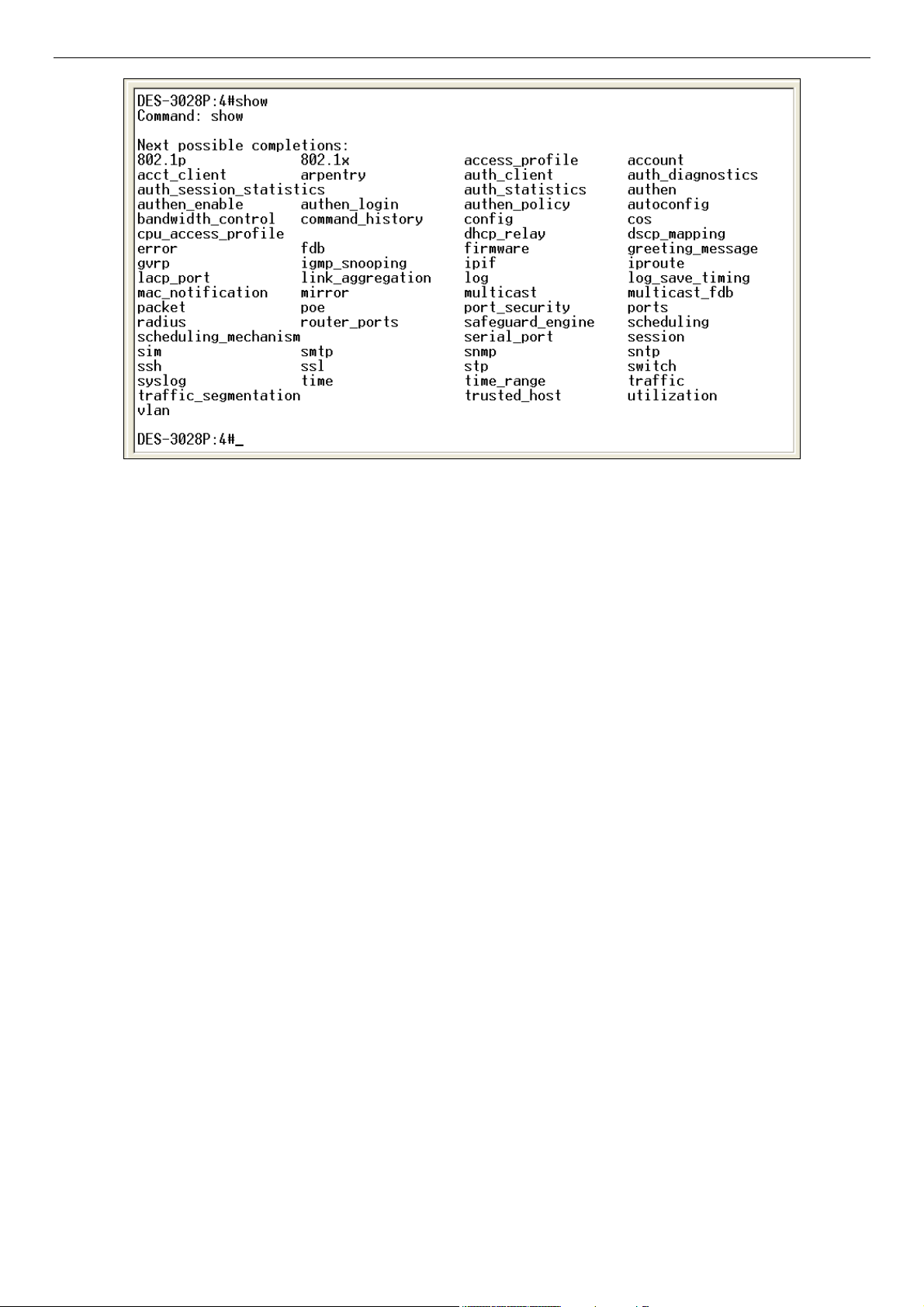
If a command is entered that is unrecognized by the CLI, the top-level commands will be displayed under the Available
commands: prompt.
Figure 2-5. The Next Available Commands Prompt
The top-level commands consist of commands such as show or config. Most of these commands require one or more parameters
to narrow the top-level command. This is equivalent to show what? or config what? Where the what? is the next parameter.
For example, if users enter the show command with no additional parameters, the CLI will then display all of the possible next
parameters.
6
Page 11
DES-3028 DES-3028P DES-3052 DES-3052P Layer 2 Fast Ethernet Switch CLI Reference Manual
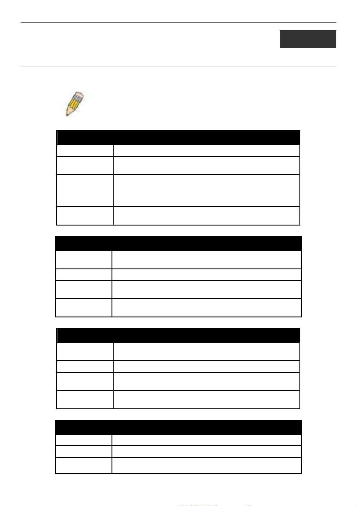
Figure 2-6. Next possible completions: Show Command
In the above example, all of the possible next parameters for the show command are displayed. At the next command prompt, the
up arrow was used to re-enter the show command, followed by the account parameter. The CLI then displays the user accounts
configured on the Switch.
7
Page 12
DES-3028 DES-3028P DES-3052 DES-3052P Layer 2 Fast Ethernet Switch CLI Reference Manual
3
COMMAND SYNTAX
The following symbols are used to describe how command entries are made and values and arguments are specified in this
manual.
Note: All commands are case-sensitive. Be sure to disable Caps Lock or
any other unwanted function that changes text case.
<angle brackets>
Purpose Encloses a variable or value that must be specified.
Syntax
Description In the above syntax example, users must supply an IP interface
Example
Command
config ipif <ipif_name 12> [{ipaddress <network_address> |
vlan <vlan_name 32> | state [enable | disable}] | bootp | dhcp]
name in the <ipif_name 12> space, a VLAN name in the
<vlan_name 32> space, and the network address in the
<network_address> space. Do not type the angle brackets.
config ipif Engineering ipaddress 10.24.22.5/255.0.0.0 vlan
Design state enable
[square brackets]
Purpose Encloses a required value or set of required arguments. One value
or argument can be specified.
Syntax
Description In the above syntax example, users must specify either an admin or
Example
Command
create account [admin | user] <username 15>
a user level account to be created. Do not type the square brackets.
create account admin Darren
| vertical bar
Purpose Separates two or more mutually exclusive items in a list, one of
which must be entered.
Syntax
Description In the above syntax example, users must specify either admin, or
Example
Command
create account [admin | user] <username 15>
user. Do not type the vertical bar.
create account admin Darren
{braces}
Purpose Encloses an optional value or set of optional arguments.
Syntax
Description In the above syntax example, users have the option to specify
reset {[config | system]}
config or system. It is not necessary to specify either optional value,
8
Page 13

DES-3028 DES-3028P DES-3052 DES-3052P Layer 2 Fast Ethernet Switch CLI Reference Manual
{braces}
however the effect of the system reset is dependent on which, if any,
value is specified. Therefore, with this example there are three
possible outcomes of performing a system reset. See the following
chapter, Basic Commands for more details about the reset
command.
Example
command
reset config
Line Editing Key Usage
Delete Deletes the character under the cursor and then shifts the
remaining characters in the line to the left.
Backspace Deletes the character to the left of the cursor and then shifts the
remaining characters in the line to the left.
Insert or Ctrl+R Toggle on and off. When toggled on, inserts text and shifts previous
text to the right.
Left Arrow Moves the cursor to the left.
Right Arrow Moves the cursor to the right.
Up Arrow Repeats the previously entered command. Each time the up arrow
is pressed, the command previous to that displayed appears. This
way it is possible to review the command history for the current
session. Use the down arrow to progress sequentially forward
through the command history list.
Down Arrow The down arrow will display the next command in the command
history entered in the current session. This displays each command
sequentially as it was entered. Use the up arrow to review previous
commands.
Tab Shifts the cursor to the next field to the left.
Multiple Page Display Control Keys
Space Displays the next page.
CTRL+c Stops the display of remaining pages when multiple pages are to be
displayed.
ESC Stops the display of remaining pages when multiple pages are to be
displayed.
n Displays the next page.
p Displays the previous page.
q Stops the display of remaining pages when multiple pages are to be
displayed.
r Refreshes the pages currently displayed.
a Displays the remaining pages without pausing between pages.
Enter Displays the next line or table entry.
9
Page 14

DES-3028 DES-3028P DES-3052 DES-3052P Layer 2 Fast Ethernet Switch CLI Reference Manual
4
BASIC SWITCH COMMANDS
The basic switch commands in the Command Line Interface (CLI) are listed (along with the appropriate parameters) in the
following table.
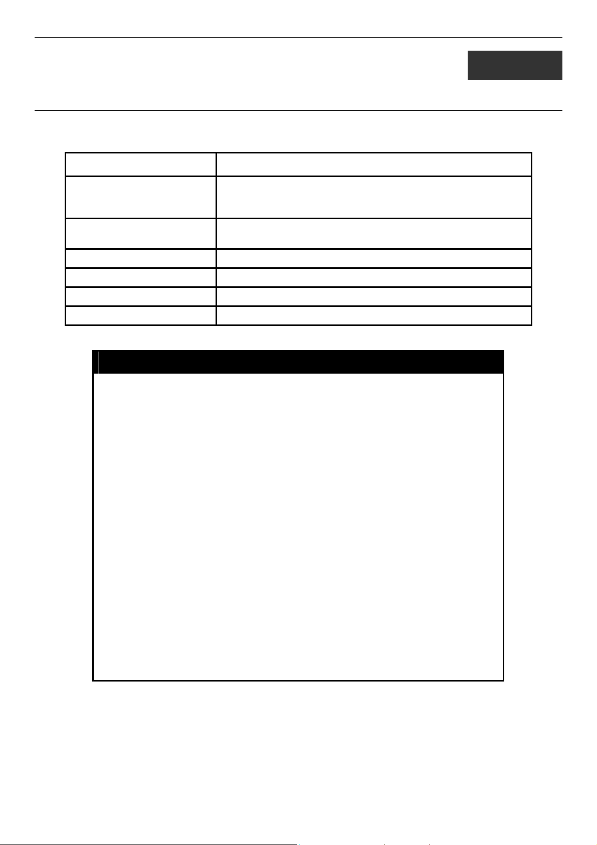
Command Parameters
create account [admin | user] <username 15>
config account <username 15>
show account
delete account <username 15>
show session
show switch
show serial_port
config serial_port {baud_rate [9600 | 19200 | 38400 | 115200] auto_logout [never | 2_minutes |
5_minutes | 10_minutes | 15_minutes]}
enable clipaging
disable clipaging
enable telnet <tcp_port_number 1-65535>
disable telnet
telnet <ipaddr> {tcp_port <value 0-65535>}
enable web <tcp_port_number 1-65535>
disable web
save
reboot
reset {[config | system]}
login
logout
Each command is listed, in detail, in the following sections.
create account
Example usage:
Purpose
Syntax create [admin | user] <username 15>
Description
Parameters admin <username>
Restrictions
Used to create user accounts.
The create account command is used to create user accounts that
consist of a username of 1 to 15 characters and a password of 0 to
15 characters. Up to 8 user accounts can be created.
user <username>
Only Administrator-level users can issue this command.
Usernames can be between 1 and 15 characters.
Passwords can be between 0 and 15 characters.
10
Page 15
DES-3028 DES-3028P DES-3052 DES-3052P Layer 2 Fast Ethernet Switch CLI Reference Manual
To create an administrator-level user account with the username “dlink”.
DES-3028P:4#create account admin dlink
Command: create account admin dlink
Enter a case-sensitive new password:****
Enter the new password again for confirmation:****
Success.
DES-3028P:4#
NOTICE: In case of lost passwords or password corruption, please refer to the
D-Link website and the White Paper entitled “Password Recovery Procedure”,
which will guide you through the steps necessary to resolve this issue.
config account
Example usage:
To configure the user password of “dlink” account:
Purpose
Syntax config account <username>
Description
Parameters <username>
Restrictions
DES-3028P:4#config account dlink
Command: config account dlink
Enter a old password:****
Enter a case-sensitive new password:****
Enter the new password again for confirmation:****
Success.
DES-3028P:4#
Used to configure user accounts
The config account command configures a user account that has
been created using the create account command.
Only Administrator-level users can issue this command.
Usernames can be between 1 and 15 characters.
Passwords can be between 0 and 15 characters.
Example usage:
To display the accounts that have been created:
show account
Purpose Used to display user accounts.
Syntax
Description Displays all user accounts created on the Switch. Up to 8 user
Parameters None.
Restrictions Only Administrator-level users can issue this command.
show account
accounts can exist at one time.
11
Page 16

DES-3028 DES-3028P DES-3052 DES-3052P Layer 2 Fast Ethernet Switch CLI Reference Manual
DES-3028P:4#show account
Command: show account
Current Accounts:
Username Access Level
--------------- -----------dlink Admin
Total Entries: 1
DES-3028P:4#
delete account
Example usage:
To delete the user account “System”:
Purpose
Syntax delete account <username>
Description
Parameters <username>
Restrictions
DES-3028P:4#delete account System
Command: delete account System
Success.
DES-3028P:4#
Used to delete an existing user account.
The delete account command deletes a user account that has
been created using the create account command.
Only Administrator-level users can issue this command.
show session
Purpose
Used to display a list of currently logged-in users.
Syntax show session
Description
Parameters
Restrictions
This command displays a list of all the users that are logged-in at
the time the command is issued.
None.
None.
12
Page 17

DES-3028 DES-3028P DES-3052 DES-3052P Layer 2 Fast Ethernet Switch CLI Reference Manual
Example usage:
To display the way that the users logged in:
DES-3028P:4#show session
Command: show session
ID Login Time Live Time From Level Name
-- ------------------------------ --------- ------------ ----- ----------8 00000 days 00:00:37 0:3:36:27 Serial Port 4 Anonymous
Total Entries: 1
CTRL+C ESC q Quit SPACE n Next Page p Previous Page r Refresh
show switch
Example usage:
To display the Switch’s information:
Purpose
Syntax show switch
Description
Parameters
Restrictions
DES-3028P:4#show switch
Command: show switch
Device Type : DES-3028P Fast Ethernet Switch
MAC Address : 00-01-02-03-04-00
IP Address : 10.90.90.91 (Manual)
VLAN Name : default
Subnet Mask : 255.0.0.0
Default Gateway : 0.0.0.0
Boot PROM Version : Build 1.00.B04
Firmware Version : Build 1.00-B22
Hardware Version : 1A1G
System Name : DES-3028P
System Location : 7th_flr_east_cabinet
System Contact : Channing_Frye_212-555-6666
Spanning Tree : Disabled
GVRP : Disabled
IGMP Snooping : Disabled
802.1x : Disabled
TELNET : Enabled (TCP 23)
WEB : Enabled (TCP 80)
RMON : Enabled
SSH : Enabled
SSL : Enabled
Clipaging : Enabled
Syslog Global State : Disabled
Dual Image : Supported
DES-3028P:4#
Used to display general information about the Switch.
This command displays information about the Switch.
None.
Only Administrator-level users can issue this command.
13
Page 18

DES-3028 DES-3028P DES-3052 DES-3052P Layer 2 Fast Ethernet Switch CLI Reference Manual
show serial_port
Example usage:
To display the serial port setting:
Purpose
Syntax show serial_port
Description
Parameters
Restrictions
DES-3028P:4#show serial_port
Command: show serial_port
Baud Rate : 9600
Data Bits : 8
Parity Bits : None
Stop Bits : 1
Auto-Logout : 10 mins
DES-3028P:4#
Used to display the current serial port settings.
This command displays the current serial port settings.
None.
None
config serial_port
Example usage:
To configure the baud rate:
Purpose
Syntax config serial_port {baud_rate [9600 | 19200 | 38400 | 115200] |
Description
Parameters
Restrictions
Used to configure the serial port.
auto_logout [never | 2_minutes | 5_minutes | 10_minutes |
15_minutes]}
This command is used to configure the serial port’s baud rate and auto
logout settings.
baud_rate [9600 | 19200 | 38400 | 115200]− The serial bit rate that will be
used to communicate with the management host. There are four options:
9600, 19200, 38400, 115200.
never − No time limit on the length of time the console can be open with
no user input.
2_minutes − The console will log out the current user if there is no user
input for 2 minutes.
5_minutes − The console will log out the current user if there is no user
input for 5 minutes.
10_minutes − The console will log out the current user if there is no user
input for 10 minutes.
15_minutes − The console will log out the current user if there is no user
input for 15 minutes.
Only administrator-level users can issue this command.
DES-3028P:4#config serial_port baud_rate 115200
Command: config serial_port baud_rate 115200
Success.
DES-3028P:4#
14
Page 19

DES-3028 DES-3028P DES-3052 DES-3052P Layer 2 Fast Ethernet Switch CLI Reference Manual
enable clipaging
Example usage:
To enable pausing of the screen display when the show command output reaches the end of the page:
Purpose
Syntax enable clipaging
Description
Parameters
Restrictions
DES-3028P:4#enable clipaging
Command: enable clipaging
Success.
DES-3028P:4#
Used to pause the scrolling of the console screen when a command
displays more than one page.
This command is used when issuing a command which causes the
console screen to rapidly scroll through several pages. This
command will cause the console to pause at the end of each page.
The default setting is enabled.
None.
Only administrator-level users can issue this command.
disable clipaging
Example usage:
To disable pausing of the screen display when show command output reaches the end of the page:
Purpose
Syntax disable clipaging
Description
Parameters
Restrictions
DES-3028P:4#disable clipaging
Command: disable clipaging
Success.
DES-3028P:4#
Used to disable the pausing of the console screen scrolling at the
end of each page when a command displays more than one screen
of information.
This command is used to disable the pausing of the console screen
at the end of each page when a command would display more than
one screen of information.
None.
Only administrator-level users can issue this command.
enable telnet
Purpose
Syntax enable telnet <tcp_port_number 1-65535>
Description
Parameters
Used to enable communication with and management of the Switch
using the Telnet protocol.
This command is used to enable the Telnet protocol on the Switch.
The user can specify the TCP or UDP port number the Switch will
use to listen for Telnet requests.
<tcp_port_number 1-65535> − The TCP port number. TCP ports
15
Page 20

DES-3028 DES-3028P DES-3052 DES-3052P Layer 2 Fast Ethernet Switch CLI Reference Manual
enable telnet
are numbered between 1 and 65535. The “well-known” TCP port for
the Telnet protocol is 23.
Example usage:
To enable Telnet and configure port number:
Example usage:
Restrictions
DES-3028P:4#enable telnet 23
Command: enable telnet 23
Success.
DES-3028P:4#
Only administrator-level users can issue this command.
disable telnet
Purpose
Syntax disable telnet
Description
Parameters
Restrictions
Used to disable the Telnet protocol on the Switch.
This command is used to disable the Telnet protocol on the Switch.
None.
Only administrator-level users can issue this command.
To disable the Telnet protocol on the Switch:
DES-3028P:4#disable telnet
Command: disable telnet
Success.
DES-3028P:4#
telnet
Purpose
Syntax telnet <ipaddr> {tcp_port <value 0-65535>}
Description
Parameters
Restrictions
Used to Telnet another device on the network.
This command is used to connect to another device’s management
through Telnet.
<ipaddr> - Enter the IP address of the device to connect through,
using Telnet.
tcp_port <value 0-65535> - Enter the TCP port number used to
connect through. The common TCP port number for telnet is 23.
Only administrator-level users can issue this command.
Example usage:
To connect to a device through telnet with a IP address of 10.53.13.99:
DES-3028P:4#telnet 10.53.13.99 tcp_port 23
Command: telnet 10.53.13.99 tcp_port 23
16
Page 21

DES-3028 DES-3028P DES-3052 DES-3052P Layer 2 Fast Ethernet Switch CLI Reference Manual
enable web
Purpose
Syntax enable web <tcp_port_number 1-65535>
Description
Parameters
Restrictions
Example usage:
To enable HTTP and configure port number:
Used to enable the HTTP-based management software on the Switch.
This command is used to enable the Web-based management software
on the Switch. The user can specify the TCP port number the Switch will
use to listen for Telnet requests.
<tcp_port_number 1-65535> − The TCP port number. TCP ports are
numbered between 1 and 65535. The “well-known” port for the Webbased management software is 80.
Only administrator-level users can issue this command.
DES-3028P:4#enable web 80
Command: enable web 80
Note: SSL will be disabled if web is enabled.
Success.
DES-3028P:4#
Example usage:
To disable HTTP:
disable web
Purpose
Syntax disable web
Description
Parameters
Restrictions
DES-3028P:4#disable web
Command: disable web
Success.
DES-3028P:4#
Used to disable the HTTP-based management software on the
Switch.
This command disables the Web-based management software on
the Switch.
None.
Only administrator-level users can issue this command.
save
Purpose
Syntax save
Description
Parameters
Used to save changes in the Switch’s configuration to non-volatile
RAM.
This command is used to enter the current switch configuration into
non-volatile RAM. The saved switch configuration will be loaded into
the Switch’s memory each time the Switch is restarted.
None
17
Page 22

DES-3028 DES-3028P DES-3052 DES-3052P Layer 2 Fast Ethernet Switch CLI Reference Manual
save
Example usage:
To save the Switch’s current configuration to non-volatile RAM:
Restrictions
DES-3028P:4#save
Command: save
Saving all configurations to NV-RAM... Done.
Success.
DES-3028P:4#
Only administrator-level users can issue this command.
reboot
Purpose
Syntax reboot
Description
Parameters
Used to restart the Switch.
This command is used to restart the Switch.
None.
Restrictions
Example usage:
To restart the Switch:
DES-3028P:4#reboot
Command: reboot
Are users sure want to proceed with the system reboot? (y|n)
Please wait, the switch is rebooting...
reset
Purpose
Syntax reset {[config | system]}
Description
Parameters
None.
Used to reset the Switch to the factory default settings.
This command is used to restore the Switch’s configuration to the
default settings assigned from the factory.
config − If the keyword ‘config’ is specified, all of the factory default
settings are restored on the Switch including the IP address, user
accounts, and the switch history log. The Switch will not save or
reboot.
system − If the keyword ‘system’ is specified all of the factory default
settings are restored on the Switch. The Switch will save and reboot
after the settings are changed to default. Rebooting will clear all
entries in the Forwarding Data Base.
If no parameter is specified, the Switch’s current IP address, user
accounts, and the switch history log are not changed. All other
parameters are restored to the factory default settings. The Switch
will not save or reboot.
Example usage:
Restrictions
Only administrator-level users can issue this command.
18
Page 23

DES-3028 DES-3028P DES-3052 DES-3052P Layer 2 Fast Ethernet Switch CLI Reference Manual
To restore all of the Switch’s parameters to their default values:
DES-3028P:4#reset config
Command: reset config
Are you sure you want to proceed with system reset?(y/n)
Success.
DES-3028P:4#
login
Purpose
Syntax login
Description
Parameters
Restrictions
Example usage:
To initiate the login procedure:
Used to log in a user to the Switch’s console.
This command is used to initiate the login procedure. The user will be
prompted for a Username and Password.
None.
None.
DES-3028P:4#login
Command: login
UserName:
logout
Purpose
Syntax logout
Description
Used to log out a user from the Switch’s console.
This command terminates the current user’s session on the Switch’s
console.
Example usage:
To terminate the current user’s console session:
Parameters
Restrictions
DES-3028P:4#logout
None.
None.
19
Page 24
DES-3028 DES-3028P DES-3052 DES-3052P Layer 2 Fast Ethernet Switch CLI Reference Manual
5
MODIFY BANNER AND PROMPT COMMANDS
Administrator level users can modify the login banner (greeting message) and command prompt by using the commands described
below.
Command Parameters
config command_ prompt [<string 16> | username | default]
config greeting_message {default}
show greeting_message
enable greeting_message
disable greeting_message
The Modify Banner and Prompt commands in the Command Line Interface (CLI) are listed (along with the appropriate
parameters) in the following table.
config command prompt
Purpose Used to configure the command prompt.
Syntax
Description Administrator level users can use this command to change the
Parameters string 16 - The command prompt can be changed by entering a
Restrictions Only administrator-level users can issue this command. Other
Example usage
To modify the command prompt to “AtYourService”:
DES-3028P:4#config command_prompt AtYourService
Command: config command_prompt AtYourService
Success.
AtYourService:4#
config command_prompt [<string 16> | username | default]
command prompt.
new name of no more that 16 characters.
username - The command prompt will be changed to the login
username.
default – The command prompt will reset to factory default
command prompt.
restrictions include:
• If the “reset/reset config” command is executed, the
modified command prompt will remain modified. However,
the “reset system” command will reset the command
prompt to the original factory banner.
config greeting _message
Purpose Used to configure the login banner (greeting message).
Syntax
Description Users can use this command to modify the login banner (greeting
config greeting _message {default}
20
Page 25

DES-3028 DES-3028P DES-3052 DES-3052P Layer 2 Fast Ethernet Switch CLI Reference Manual
config greeting _message
message).
Parameters default – If the user enters default to the modify banner command, then
the banner will be reset to the original factory banner.
To open the Banner Editor, click Enter after typing the config
greeting_message command. Type the information to be displayed on
the banner by using the commands described on the Banner Editor:
Quit without save: Ctrl+C
Save and quit: Ctrl+W
Move cursor: Left/Right/Up/Down
Delete line: Ctrl+D
Erase all setting: Ctrl+X
Reload original setting: Ctrl+L
Restrictions Only administrator-level users can issue this command. Other restrictions
include:
• If the “reset/reset config” command is executed, the modified
banner will remain modified. However, the “reset system”
command will reset the modified banner to the original factory
banner.
• The capacity of the banner is 6*80. 6 Lines and 80 characters per
line.
• Ctrl+W will only save the modified banner in the DRAM. Users
need to type the “save” command to save it into FLASH.
• Only valid in threshold level.
Example usage:
To modify the banner to read “Say goodnight, Gracie”:
DES-3028P:4# config greeting_message
Command: config greeting_message
Greeting Messages Editor
================================================================================
Say Goodnight, Gracie
DGS-3028P Fast Ethernet Switch
Command Line Interface
Firmware: Build 1.00-B22
Copyright(C) 2006-2009D-Link Corporation. All rights reserved.
================================================================================
<Function Key> <Control Key>
Ctrl+C Quit without save left/right/
Ctrl+W Save and quit up/down Move cursor
Ctrl+D Delete line
Ctrl+X Erase all setting
Ctrl+L Reload original setting
--------------------------------------------------------------------------------------------------------------------------------------------
21
Page 26

DES-3028 DES-3028P DES-3052 DES-3052P Layer 2 Fast Ethernet Switch CLI Reference Manual
show greeting_message
Purpose Used to view the currently configured greeting message
configured on the Switch.
Syntax
Description This command is used to view the currently configured greeting
Parameters None.
Restrictions None.
Example usage:
To view the currently configured greeting message:
DES-3028P:4#show greeting_message
Command: show greeting_message
=========================================================================
DES-3028P Fast Ethernet Switch
Command Line Interface
Firmware: Build 1.00-B22
Copyright(C) 2006-2009 D-Link Corporation. All rights reserved.
=========================================================================
DES-3028P:4#
show greeting_message
message on the Switch.
22
Page 27

DES-3028 DES-3028P DES-3052 DES-3052P Layer 2 Fast Ethernet Switch CLI Reference Manual
6
SWITCH PORT COMMANDS
The switch port commands in the Command Line Interface (CLI) are listed (along with the appropriate parameters) in the
following table.
Command Parameters
config ports [<portlist> | all] {medium_type [fiber | copper]} {speed [auto | 10_half | 10_full | 100_half
| 100_full | 1000_full {[master | slave]}] | flow_control [enable | disable] | learning
[enable | disable] | state [enable | disable] | [description <desc 1-32> |
clear_description]}
show ports [<portlist>] {description}
Each command is listed, in detail, in the following sections.
config ports
Purpose Used to configure the Switch’s Ethernet port settings.
Syntax
Description This command allows for the configuration of the Switch’s Ethernet ports. Only the ports listed in
Parameters
[<portlist> | all] {medium_type [fiber | copper]} {speed [auto | 10_half | 10_full | 100_half |
100_full | 1000_full {[master | slave]}] | flow_control [enable | disable] | learning [enable |
disable] | state [enable | disable] | [description <desc 1-32> | clear_description]}
the <portlist> will be affected.
all − Configure all ports on the Switch.
<portlist> − Specifies a port or range of ports to be configured.
medium_type [fiber | copper] – This applies only to the Combo ports. If configuring the Combo
ports this defines the type of transport medium used.
speed – Allows the user to adjust the speed for a port or range of ports. The user has a choice of
the following:
• auto − Enables auto-negotiation for the specified range of ports.
• [10 | 100 | 1000] − Configures the speed in Mbps for the specified range of ports. Gigabit
ports are statically set to 1000 and cannot be set to slower speeds.
• [half | full] − Configures the specified range of ports as either full-duplex or half-duplex.
• [master | slave] - The master setting (1000M/Full_M) will allow the port to advertise
capabilities related to duplex, speed and physical layer type. The master setting will also
determine the master and slave relationship between the two connected physical layers.
This relationship is necessary for establishing the timing control between the two physical
layers. The timing control is set on a master physical layer by a local source. The slave
setting (1000M/Full_S) uses loop timing, where the timing comes form a data stream
received from the master. If one connection is set for 1000M/Full_M, the other side of the
connection must be set for 1000M/Full_S. Any other configuration will result in a link
down status for both ports.
flow_control [enable | disable] – Enable or disable flow control for the specified ports.
learning [enable | disable] − Enables or disables the MAC address learning on the specified
range of ports.
state [enable | disable] − Enables or disables the specified range of ports.
description <desc 32> - Enter an alphanumeric string of no more than 32 characters to describe
a selected port interface.
clear_description - Enter this command to clear the port description of the selected port(s).
Restrictions Only administrator-level users can issue this command.
23
Page 28

DES-3028 DES-3028P DES-3052 DES-3052P Layer 2 Fast Ethernet Switch CLI Reference Manual
Example usage:
To configure the speed of port 3 to be 10 Mbps, full duplex, with learning and state enabled:
DES-3028P:4#config ports 1-3 speed 10_full state enable
Command: config ports 1-3 speed 10_full state enable
Success.
DES-3028P:4#
show ports
Example usage:
To display the configuration of all ports on a standalone switch:
Purpose
Syntax show ports [<portlist>] {description | err_disabled}
Description
Parameters
Restrictions
DES-3028P:4#show ports
Command show ports
Port Port Settings Connection Address
State Speed/Duplex/FlowCtrl Speed/Duplex/FlowCtrl Learning
------ -------- --------------------- --------------------- -------1 Enabled Auto/Enabled Link Down Enabled
2 Enabled Auto/Enabled Link Down Enabled
3 Enabled Auto/Enabled Link Down Enabled
4 Enabled Auto/Enabled Link Down Enabled
5 Enabled Auto/Enabled Link Down Enabled
6 Enabled Auto/Enabled Link Down Enabled
7 Enabled Auto/Enabled Link Down Enabled
8 Enabled Auto/Enabled Link Down Enabled
9 Enabled Auto/Enabled Link Down Enabled
10 Enabled Auto/Enabled 100M/Full/None Enabled
11 Enabled Auto/Enabled Link Down Enabled
12 Enabled Auto/Enabled Link Down Enabled
13 Enabled Auto/Disabled Link Down Enabled
14 Enabled Auto/Disabled Link Down Enabled
15 Enabled Auto/Disabled Link Down Enabled
16 Enabled Auto/Disabled Link Down Enabled
17 Enabled Auto/Disabled Link Down Enabled
18 Enabled Auto/Disabled Link Down Enabled
19 Enabled Auto/Disabled Link Down Enabled
20 Enabled Auto/Disabled Link Down Enabled
CTRL+C ESC q Quit SPACE n Next Page p Previous Page r Refresh
Used to display the current configuration of a range of ports.
This command is used to display the current configuration of a
range of ports.
<portlist> − Specifies a port or range of ports to be displayed.
{description} – Adding this parameter to the show ports command
indicates that a previously entered port description will be included
in the display.
err_disabled – Use this to list disabled ports including connection
status and reason for being disabled.
None.
24
Page 29

DES-3028 DES-3028P DES-3052 DES-3052P Layer 2 Fast Ethernet Switch CLI Reference Manual
Example usage:
To display the configuration of all ports on a standalone switch, with description:
DES-3028P:4#show ports description
Command: show ports description
Port Port Settings Connection Address
State Speed/Duplex/FlowCtrl Speed/Duplex/FlowCtrl Learning
------ -------- --------------------- --------------------- -------1 Enabled Auto/Disabled Link Down Enabled
Desc: dads1
2 Enabled Auto/Disabled Link Down Enabled
Desc:
3 Enabled Auto/Disabled Link Down Enabled
Desc:
4 Enabled Auto/Disabled Link Down Enabled
Desc:
5 Enabled Auto/Disabled Link Down Enabled
Desc:
6 Enabled Auto/Disabled Link Down Enabled
Desc:
7 Enabled Auto/Disabled Link Down Enabled
Desc:
8 Enabled Auto/Disabled Link Down Enabled
Desc:
9 Enabled Auto/Disabled Link Down Enabled
Desc:
10 Enabled Auto/Disabled Link Down Enabled
Desc:
CTRL+C ESC q Quit SPACE n Next Page p Previous Page r Refresh
25
Page 30
DES-3028 DES-3028P DES-3052 DES-3052P Layer 2 Fast Ethernet Switch CLI Reference Manual
7
PORT SECURITY COMMANDS
The Switch’s port security commands in the Command Line Interface (CLI) are listed (along with the appropriate parameters) in
the following table.
Command Parameters
config port_security ports [<auth_portlist> | all] {admin_state [enable| disable] |
max_learning_addr <max_lock_no 0-16> | lock_address_mode
[DeleteOnTimeout | DeleteOnReset | Permanent]}
delete port_security entry vlan_name <vlan_name 32> mac_address <macaddr> port
<auth_port>
clear port_security_entry port <auth_portlist>
show port_security {ports <auth_portlist>}
enable port_security trap_log
disable port_security trap_log
Each command is listed, in detail, in the following sections.
config port_security ports
Purpose
Syntax config port_security ports [<auth_portlist> | all ] {admin_state
Description
Parameters
Used to configure port security settings.
[enable| disable] | max_learning_addr <max_lock_no 0-16> |
lock_address_mode [Permanent | DeleteOnTimeout |
DeleteOnReset]}
This command allows for the configuration of the port security feature.
Only the ports listed in the <auth_portlist> are affected.
auth_portlist − Specifies a port or range of ports to be configured.
all − Configure port security for all ports on the Switch.
admin_state [enable | disable] – Enable or disable port security for the
listed ports.
max_learning_addr <max_lock_no 0-16> - Use this to limit the number of
MAC addresses dynamically listed in the FDB for the ports.
lock_address_mode [Permanent | DeleteOnTimout | DeleteOnReset] –
Indicates the method of locking addresses. The user has three choices:
Permanent – The locked addresses will not age out after the
aging timer expires.
DeleteOnTimeout – The locked addresses will age out after the
aging timer expires.
DeleteOnReset – The locked addresses will not age out until the
Switch has been reset.
Example usage:
To configure the port security:
Restrictions
Only administrator-level users can issue this command.
26
Page 31

DES-3028 DES-3028P DES-3052 DES-3052P Layer 2 Fast Ethernet Switch CLI Reference Manual
DES-3028P:4#config port_security ports 1-5 admin_state enable
max_learning_addr 5 lock_address_mode DeleteOnReset
Command: config port_security ports 1-5 admin_state enable
max_learning_addr 5 lock_address_mode DeleteOnReset
Success.
DES-3028P:4#
delete port_security_entry
Purpose
Syntax delete port_security_entry vlan name <vlan_name 32>
Description
Parameters
Restrictions
Example usage:
To delete a port security entry:
DES-3028P:4#delete port_security_entry vlan_name default
mac_address 00-01-30-10-2C-C7 port 6
Command: delete port_security_entry vlan_name default
mac_address 00-01-30-10-2C-C7 port 6
Success.
DES-3028P:4#
Used to delete a port security entry by MAC address, port number
and VLAN ID.
mac_address <macaddr> port <auth_port>
This command is used to delete a single, previously learned port
security entry by port, VLAN name, and MAC address.
vlan name <vlan_name 32> - Enter the corresponding VLAN name
of the port to delete.
mac_address <macaddr> - Enter the corresponding MAC address,
previously learned by the port, to delete.
port <auth_port> - Enter the port number which has learned the
previously entered MAC address.
Only administrator-level users can issue this command.
clear port_security_entry
Purpose
Syntax clear port_security_entry ports <auth_portlist>
Description
Parameters
Restrictions
Example usage:
To clear a port security entry by port:
Used to clear MAC address entries learned from a specified port for
the port security function.
This command is used to clear MAC address entries which were
learned by the Switch by a specified port. This command only relates
to the port security function.
<auth_portlist> − Specifies a port or port range to clear.
Only administrator-level users can issue this command.
27
Page 32

DES-3028 DES-3028P DES-3052 DES-3052P Layer 2 Fast Ethernet Switch CLI Reference Manual
DES-3028P:4# clear port_security_entry port 6
Command: clear port_security_entry port 6
Success.
DES-3028P:4#
show port_security
Example usage:
To display the port security configuration:
Purpose
Syntax show port_security {ports <auth_portlist>}
Description
Parameters
Restrictions
DES-3028P:4#show port_security ports 1-5
Command: show port_security ports 1-5
Port_security Trap/Log : Disabled
Port Admin State Max. Learning Addr. Lock Address Mode
---- ----------- ------------------- ----------------1 Disabled 1 DeleteOnReset
2 Disabled 1 DeleteOnReset
3 Disabled 1 DeleteOnReset
4 Disabled 1 DeleteOnReset
5 Disabled 1 DeleteOnReset
CTRL+C ESC q Quit SPACE n Next Page p Previous Page r Refresh
Used to display the current port security configuration.
This command is used to display port security information of the
Switch’s ports. The information displayed includes port security,
admin state, maximum number of learning address and lock mode.
<auth_portlist> − Specifies a port or range of ports to be viewed.
None.
Example usage:
To enable the port security trap log setting:
enable port_security trap_log
Purpose
Syntax enable port_security trap_log
Description
Parameters
Restrictions
Used to enable the trap log for port security.
This command, along with the disable port_security trap_log, will
enable and disable the sending of log messages to the Switch’s log
and SNMP agent when the port security of the Switch has been
triggered.
None.
None.
DES-3028P:4#enable port_security trap_log
Command: enable port_security trap_log
Success.
DES-3028P:4#
28
Page 33

DES-3028 DES-3028P DES-3052 DES-3052P Layer 2 Fast Ethernet Switch CLI Reference Manual
disable port_security trap_log
Example usage:
To enable the port security trap log setting:
Purpose
Syntax disable port_security trap_log
Description
Parameters
Restrictions
Used to disable the trap log for port security.
This command, along with the enable port_security trap_log, will
enable and disable the sending of log messages to the Switch’s log
and SNMP agent when the port security of the Switch has been
triggered.
None.
None.
DES-3028P:4#enable port_security trap_log
Command: enable port_security trap_log
Success.
DES-3028P:4#
29
Page 34

DES-3028 DES-3028P DES-3052 DES-3052P Layer 2 Fast Ethernet Switch CLI Reference Manual
8
NETWORK MANAGEMENT (SNMP) COMMANDS
The DES-3028/28P/52/52P support the Simple Network Management Protocol (SNMP) versions 1, 2c, and 3. Users can specify
which version of the SNMP users want to use to monitor and control the Switch. The three versions of SNMP vary in the level of
security provided between the management station and the network device. The following table lists the security features of the
three SNMP versions:
SNMP
Version
v1 Community String
v2c Community String
v3 Username
v3 MD5 or SHA Authentication is based on the HMAC-MD5 or HMAC-SHA
v3 MD5 DES or SHA DES Authentication is based on the HMAC-MD5 or HMAC-SHA
The network management commands in the Command Line Interface (CLI) are listed (along with the appropriate parameters) in
the following table.
Authentication
Method
Description
Community String is used for authentication − NoAuthNoPriv
Community String is used for authentication − NoAuthNoPriv
Username is used for authentication − NoAuthNoPriv
algorithms − AuthNoPriv
algorithms − AuthPriv.
DES 56-bit encryption is added based on the CBC-DES (DES-56)
standard
Command Parameters
create snmp user <SNMP_name 32> <groupname 32> {encrypted [by_password
auth [md5 <auth_password 8-16 > | sha <auth_password 8-20>]
priv [none | des <priv_password 8-16>] | by_key auth [md5
<auth_key 32-32> | sha <auth_key 40-40>] priv [none | des
<priv_key 32-32>]]}
delete snmp user <SNMP_name 32>
show snmp user
create snmp view <view_name 32> <oid> view_type [included | excluded]
delete snmp view <view_name 32> [all | oid]
show snmp view <view_name 32>
create snmp community <community_string 32> view <view_name 32> [read_only |
read_write]
delete snmp community <community_string 32>
show snmp community <community_string 32>
config snmp engineID <snmp_engineID 10-64>
show snmp engineID
create snmp group <groupname 32> {v1 | v2c | v3 [noauth_nopriv | auth_nopriv |
auth_priv]} {read_view <view_name 32> | write_view
<view_name 32> | notify_view <view_name 32>}
delete snmp group <groupname 32>
show snmp groups
create snmp host <ipaddr> {v1 | v2c | v3 [noauth_nopriv | auth_nopriv | auth_priv]}
<auth_string 32>
30
Page 35

DES-3028 DES-3028P DES-3052 DES-3052P Layer 2 Fast Ethernet Switch CLI Reference Manual
Command Parameters
delete snmp host <ipaddr>
show snmp host <ipaddr>
create trusted_host <ipaddr>
delete trusted_host <ipaddr>
show trusted_host <ipaddr>
enable snmp traps
enable snmp authenticate traps
show snmp traps
disable snmp traps
disable snmp authenticate traps
config snmp system_contact <sw_contact>
config snmp system_location <sw_location>
config snmp system_name <sw_name>
enable rmon
disable rmon
Each command is listed, in detail, in the following sections.
create snmp user
Purpose
Syntax create snmp user <SNMP_name 32> <groupname 32> {encrypted
Description
Parameters
Used to create a new SNMP user and adds the user to an SNMP group that is also
created by this command.
[by_password auth [md5 <auth_password 8-16> | sha <auth_password 8-20>]
priv [none | des <priv_password 8-16>] | by_key auth [md5 <auth_key 32-32> |
sha <auth_key 40-40>] priv [none | des <priv_key 32-32>]]}
The create snmp user command creates a new SNMP user and adds the user to
an SNMP group that is also created by this command. SNMP ensures:
Message integrity − Ensures that packets have not been tampered with during
transit.
Authentication − Determines if an SNMP message is from a valid source.
Encryption − Scrambles the contents of messages to prevent it from being viewed
by an unauthorized source.
<SNMP_name 32> − An alphanumeric name of up to 32 characters that will identify
the new SNMP user.
<groupname 32> − An alphanumeric name of up to 32 characters that will identify
the SNMP group the new SNMP user will be associated with.
encrypted – Allows the user to choose a type of authorization for authentication
using SNMP. The user may choose:
•
by_password – Requires the SNMP user to enter a password for
authentication and privacy. The password is defined by specifying the
auth_password below. This method is recommended.
•
by_key – Requires the SNMP user to enter a encryption key for
authentication and privacy. The key is defined by specifying the key in hex
form below. This method is not recommended.
auth - The user may also choose the type of authentication algorithms used to
authenticate the snmp user. The choices are:
•
md5 − Specifies that the HMAC-MD5-96 authentication level will be used.
md5 may be utilized by entering one of the following:
31
Page 36

DES-3028 DES-3028P DES-3052 DES-3052P Layer 2 Fast Ethernet Switch CLI Reference Manual
create snmp user
• <auth password 8-16> - An alphanumeric sting of between 8 and
16 characters that will be used to authorize the agent to receive
packets for the host.
• <auth_key 32-32> - Enter an alphanumeric sting of exactly 32
characters, in hex form, to define the key that will be used to
authorize the agent to receive packets for the host.
•
sha − Specifies that the HMAC-SHA-96 authentication level will be used.
• <auth password 8-20> - An alphanumeric sting of between 8 and
20 characters that will be used to authorize the agent to receive
packets for the host.
• <auth_key 40-40> - Enter an alphanumeric sting of exactly 40
characters, in hex form, to define the key that will be used to
authorize the agent to receive packets for the host.
priv – Adding the priv (privacy) parameter will allow for encryption in addition to the
authentication algorithm for higher security. The user may choose:
•
des – Adding this parameter will allow for a 56-bit encryption to be added
using the DES-56 standard using:
• <priv_password 8-16> - An alphanumeric string of between 8 and
16 characters that will be used to encrypt the contents of messages
the host sends to the agent.
• <priv_key 32-32> - Enter an alphanumeric key string of exactly 32
characters, in hex form, that will be used to encrypt the contents of
messages the host sends to the agent.
•
none – Adding this parameter will add no encryption.
Restrictions
Only administrator-level users can issue this command.
Example usage:
To create an SNMP user on the Switch:
DES-3028P:4#create snmp user dlink default encrypted by_password auth md5
canadian priv none
Command: create snmp user dlink default encrypted by_password auth md5
canadian priv none
Success.
DES-3028P:4#
delete snmp user
Purpose
Syntax delete snmp user <SNMP_name 32>
Description
Parameters
Restrictions
Used to remove an SNMP user from an SNMP group and also to
delete the associated SNMP group.
The delete snmp user command removes an SNMP user from its
SNMP group and then deletes the associated SNMP group.
<SNMP_name 32> − An alphanumeric string of up to 32 characters
that identifies the SNMP user that will be deleted.
Only administrator-level users can issue this command.
32
Page 37

DES-3028 DES-3028P DES-3052 DES-3052P Layer 2 Fast Ethernet Switch CLI Reference Manual
Example usage:
To delete a previously entered SNMP user on the Switch:
DES-3028P:4#delete snmp user dlink
Command: delete snmp user dlink
Success.
DES-3028P:4#
show snmp user
Purpose Used to display information about each SNMP username in the
SNMP group username table.
Example usage:
To display the SNMP users currently configured on the Switch:
Syntax
Description The show snmp user command displays information about each
Parameters None.
Restrictions Only administrator-level users can issue this command.
DES-3028P:4#show snmp user
Command: show snmp user
Username Group Name SNMP Version Auth-Protocol PrivProtocol
--------------- -------------- ------------ ----------------- ----------------initial initial V3 None None
Total Entries: 1
DES-3028P:4#
show snmp user
SNMP username in the SNMP group username table.
create snmp view
Example usage:
Purpose Used to assign views to community strings to limit which MIB objects
and SNMP manager can access.
Syntax create snmp view <view_name 32> <oid> view_type [included |
excluded]
Description The create snmp view command assigns views to community
strings to limit which MIB objects an SNMP manager can access.
Parameters <view_name 32> − An alphanumeric string of up to 32 characters
that identifies the SNMP view that will be created.
<oid> − The object ID that identifies an object tree (MIB tree) that will
be included or excluded from access by an SNMP manager.
view type – Sets the view type to be:
• • included − Include this object in the list of objects that an
SNMP manager can access.
excluded − Exclude this object from the list of objects that
an SNMP manager can access.
Restrictions Only administrator-level users can issue this command.
33
Page 38

DES-3028 DES-3028P DES-3052 DES-3052P Layer 2 Fast Ethernet Switch CLI Reference Manual
To create an SNMP view:
DES-3028P:4#create snmp view dlinkview 1.3.6 view_type included
Command: create snmp view dlinkview 1.3.6 view_type included
Success.
DES-3028P:4#
delete snmp view
Purpose Used to remove an SNMP view entry previously created on the
Switch.
Example usage:
To delete a previously configured SNMP view from the Switch:
Syntax
Description The delete snmp view command is used to remove an SNMP view
Parameters
Restrictions Only administrator-level users can issue this command.
DES-3028P:4#delete snmp view dlinkview all
Command: delete snmp view dlinkview all
Success.
DES-3028P:4#
delete snmp view <view_name 32> [all | <oid>]
previously created on the Switch.
<view_name 32> − An alphanumeric string of up to 32 characters that
identifies the SNMP view to be deleted.
all − Specifies that all of the SNMP views on the Switch will be
deleted.
<oid> − The object ID that identifies an object tree (MIB tree) that will
be deleted from the Switch.
Example usage:
To display SNMP view configuration:
show snmp view
Purpose Used to display an SNMP view previously created on the Switch.
Syntax
Description The show snmp view command displays an SNMP view
Parameters
Restrictions None.
show snmp view {<view_name 32>}
previously created on the Switch.
<view_name 32> − An alphanumeric string of up to 32 characters
that identifies the SNMP view that will be displayed.
34
Page 39

DES-3028 DES-3028P DES-3052 DES-3052P Layer 2 Fast Ethernet Switch CLI Reference Manual
DES-3028P:4#show snmp view
Command: show snmp view
Vacm View Table Settings
View Name Subtree View Type
-------------------- ------------------------- --------- ReadView 1 Included
WriteView 1 Included
NotifyView 1.3.6 Included
restricted 1.3.6.1.2.1.1 Included
restricted 1.3.6.1.2.1.11 Included
restricted 1.3.6.1.6.3.10.2.1 Included
restricted 1.3.6.1.6.3.11.2.1 Included
restricted 1.3.6.1.6.3.15.1.1 Included
CommunityView 1 Included
CommunityView 1.3.6.1.6.3 Excluded
CommunityView 1.3.6.1.6.3.1 Included
Total Entries: 11
DES-3028P:4#
create snmp community
Purpose Used to create an SNMP community string to define the relationship
between the SNMP manager and an agent. The community string acts like
a password to permit access to the agent on the Switch. One or more of the
following characteristics can be associated with the community string:
An Access List of IP addresses of SNMP managers that are permitted to
use the community string to gain access to the Switch’s SNMP agent.
An MIB view that defines the subset of all MIB objects that will be
accessible to the SNMP community.
read_write or read_only level permission for the MIB objects accessible to
the SNMP community.
Syntax
Description
Parameters
create snmp community <community_string 32> view <view_name 32>
[read_only | read_write]
The create snmp community command is used to create an SNMP
community string and to assign access-limiting characteristics to this
community string.
<community_string 32> − An alphanumeric string of up to 32 characters that
is used to identify members of an SNMP community. This string is used like
a password to give remote SNMP managers access to MIB objects in the
Switch’s SNMP agent.
view <view_name 32> − An alphanumeric string of up to 32 characters that
is used to identify the group of MIB objects that a remote SNMP manager is
allowed to access on the Switch.
read_only − Specifies that SNMP community members using the community
string created with this command can only read the contents of the MIBs on
the Switch.
read_write − Specifies that SNMP community members using the
community string created with this command can read from and write to the
contents of the MIBs on the Switch.
Restrictions Only administrator-level users can issue this command.
Example usage:
To create the SNMP community string “dlink:”
35
Page 40

DES-3028 DES-3028P DES-3052 DES-3052P Layer 2 Fast Ethernet Switch CLI Reference Manual
DES-3028P:4#create snmp community dlink view ReadView read_write
Command: create snmp community dlink view ReadView read_write
Success.
DES-3028P:4#
delete snmp community
Purpose Used to remove a specific SNMP community string from the Switch.
Example usage:
To delete the SNMP community string “dlink:”
Syntax
Description The delete snmp community command is used to remove a
Parameters
Restrictions Only administrator-level users can issue this command.
DES-3028P:4#delete snmp community dlink
Command: delete snmp community dlink
Success.
DES-3028P:4#
delete snmp community <community_string 32>
previously defined SNMP community string from the Switch.
<community_string 32> − An alphanumeric string of up to 32
characters that is used to identify members of an SNMP community.
This string is used like a password to give remote SNMP managers
access to MIB objects in the Switch’s SNMP agent.
show snmp community
Example usage:
To display the currently entered SNMP community strings:
Purpose Used to display SNMP community strings configured on the Switch.
Syntax
Description The show snmp community command is used to display SNMP
Parameters
Restrictions None.
show snmp community {<community_string 32>}
community strings that are configured on the Switch.
<community_string 32> − An alphanumeric string of up to 32
characters that is used to identify members of an SNMP community.
This string is used like a password to give remote SNMP managers
access to MIB objects in the Switch’s SNMP agent.
36
Page 41

DES-3028 DES-3028P DES-3052 DES-3052P Layer 2 Fast Ethernet Switch CLI Reference Manual
DES-3028P:4#show snmp community
Command: show snmp community
SNMP Community Table
Community Name View Name Access Right
-------------------------------- ------------------------------- -----------private CommunityView read_write
public CommunityView read_only
dlink ReadView read_write
Total Entries: 3
DES-3028P:4#
config snmp engineID
Purpose Used to configure a name for the SNMP engine on the Switch.
Example usage:
To give the SNMP agent on the Switch the name “0035636666”
Syntax
Description The config snmp engineID command configures a name for the
Parameters
Restrictions Only administrator-level users can issue this command.
DES-3028P:4#config snmp engineID 0035636666
Command: config snmp engineID 0035636666
Success.
DES-3028P:4#
config snmp engineID <snmp_engineID>
SNMP engine on the Switch.
<snmp_engineID> − An alphanumeric string that will be used to
identify the SNMP engine on the Switch.
show snmp engineID
Purpose Used to display the identification of the SNMP engine on the Switch.
Syntax
show snmp engineID
Example usage:
To display the current name of the SNMP engine on the Switch:
Description The show snmp engineID command displays the identification of
the SNMP engine on the Switch.
Parameters None.
Restrictions None.
DES-3028P:4#show snmp engineID
Command: show snmp engineID
SNMP Engine ID : 0035636666
DES-3028P:4#
37
Page 42

DES-3028 DES-3028P DES-3052 DES-3052P Layer 2 Fast Ethernet Switch CLI Reference Manual
create snmp group
Purpose
Syntax create snmp group <groupname 32> [v1 | v2c | v3 [noauth_nopriv
Description
Parameters
Restrictions
Used to create a new SNMP group, or a table that maps SNMP users
to SNMP views.
| auth_nopriv | auth_priv]] {read_view <view_name 32> |
write_view <view_name 32> | notify_view <view_name 32>}
The create snmp group command creates a new SNMP group, or a
table that maps SNMP users to SNMP views.
<groupname 32> − An alphanumeric name of up to 32 characters that
will identify the SNMP group the new SNMP user will be associated
with.
v1 – Specifies that SNMP version 1 will be used. The Simple Network
Management Protocol (SNMP), version 1, is a network management
protocol that provides a means to monitor and control network
devices.
v2c – Specifies that SNMP version 2c will be used. The SNMP v2c
supports both centralized and distributed network management
strategies. It includes improvements in the Structure of Management
Information (SMI) and adds some security features.
v3 – Specifies that the SNMP version 3 will be used. SNMP v3
provides secure access to devices through a combination of
authentication and encrypting packets over the network. SNMP v3
adds:
• Message integrity − Ensures that packets have
not been tampered with during transit.
• Authentication − Determines if an SNMP
message is from a valid source.
• Encryption − Scrambles the contents of
messages to prevent it being viewed by an
unauthorized source.
noauth_nopriv − Specifies that there will be no authorization and no
encryption of packets sent between the Switch and a remote SNMP
manager.
auth_nopriv − Specifies that authorization will be required, but there
will be no encryption of packets sent between the Switch and a
remote SNMP manager.
auth_priv − Specifies that authorization will be required, and that
packets sent between the Switch and a remote SNMP manger will be
encrypted.
read_view – Specifies that the SNMP group being created can
request SNMP messages.
write_view – Specifies that the SNMP group being created has write
privileges.
notify_view − Specifies that the SNMP group being created can
receive SNMP trap messages generated by the Switch’s SNMP
agent.
• <view_name 32> − An alphanumeric string of up to 32
characters that is used to identify the group of MIB objects
that a remote SNMP manager is allowed to access on the
Switch.
Only administrator-level users can issue this command.
Example usage:
To create an SNMP group named “sg1:”
38
Page 43

DES-3028 DES-3028P DES-3052 DES-3052P Layer 2 Fast Ethernet Switch CLI Reference Manual
DES-3028P:4#create snmp group sg1 v3 noauth_nopriv read_view v1
write_view v1 notify_view v1
Command: create snmp group sg1 v3 noauth_nopriv read_view v1
write_view v1 notify_view v1
Success.
DES-3028P:4#
delete snmp group
Example usage:
To delete the SNMP group named “sg1”.
show snmp groups
Purpose
Purpose
Syntax delete snmp group <groupname 32>
Description
Parameters
Restrictions
DES-3028P:4#delete snmp group sg1
Command: delete snmp group sg1
Success.
DES-3028P:4#
Used to remove an SNMP group from the Switch.
The delete snmp group command is used to remove an SNMP
group from the Switch.
<groupname 32> − An alphanumeric name of up to 32 characters that
will identify the SNMP group the new SNMP user will be associated
with.
Only administrator-level users can issue this command.
Used to display the group-names of SNMP groups currently configured on
the Switch. The security model, level, and status of each group are also
displayed.
Syntax show snmp groups
Description
Parameters
Restrictions
Example usage:
To display the currently configured SNMP groups on the Switch:
The show snmp groups command displays the group-names of SNMP
groups currently configured on the Switch. The security model, level, and
status of each group are also displayed.
None.
None.
39
Page 44

DES-3028 DES-3028P DES-3052 DES-3052P Layer 2 Fast Ethernet Switch CLI Reference Manual
DES-3028P:4#show snmp groups
Command: show snmp groups
Vacm Access Table Settings
Group Name : Group3
ReadView Name : ReadView
WriteView Name : WriteView
Notify View Name : NotifyView
Security Model : SNMPv3
Security Level : NoAuthNoPriv
Group Name : Group4
ReadView Name : ReadView
WriteView Name : WriteView
Notify View Name : NotifyView
Security Model : SNMPv3
Security Level : authNoPriv
Group Name : Group5
ReadView Name : ReadView
WriteView Name : WriteView
Notify View Name : NotifyView
Security Model : SNMPv3
Security Level : authNoPriv
Group Name : initial
ReadView Name : restricted
WriteView Name :
Notify View Name : restricted
Security Model : SNMPv3
Security Level : NoAuthNoPriv
Group Name : ReadGroup
ReadView Name : CommunityView
WriteView Name :
Notify View Name : CommunityView
Security Model : SNMPv1
Security Level : NoAuthNoPriv
Total Entries: 5
DES-3028P:4#
create snmp host
Purpose Used to create a recipient of SNMP traps generated by the Switch’s
SNMP agent.
Syntax
Description The create snmp host command creates a recipient of SNMP traps
Parameters
create snmp host <ipaddr> [v1 | v2c | v3 [noauth_nopriv |
auth_nopriv | auth_priv] <auth_string 32>]
generated by the Switch’s SNMP agent.
<ipaddr> − The IP address of the remote management station that will
serve as the SNMP host for the Switch.
v1 – Specifies that SNMP version 1 will be used. The Simple Network
Management Protocol (SNMP), version 1, is a network management
protocol that provides a means to monitor and control network devices.
v2c – Specifies that SNMP version 2c will be used. The SNMP v2c
supports both centralized and distributed network management
40
Page 45

DES-3028 DES-3028P DES-3052 DES-3052P Layer 2 Fast Ethernet Switch CLI Reference Manual
create snmp host
strategies. It includes improvements in the Structure of Management
Information (SMI) and adds some security features.
v3 – Specifies that the SNMP version 3 will be used. SNMP v3
provides secure access to devices through a combination of
authentication and encrypting packets over the network. SNMP v3
adds:
•
Message integrity − ensures that packets have not been
tampered with during transit.
•
Authentication − determines if an SNMP message is from a
valid source.
•
Encryption − scrambles the contents of messages to prevent
it being viewed by an unauthorized source.
noauth_nopriv
encryption of packets sent between the Switch and a remote SNMP
manager.
auth_nopriv − Specifies that authorization will be required, but there
will be no encryption of packets sent between the Switch and a remote
SNMP manager.
auth_priv − Specifies that authorization will be required, and that
packets sent between the Switch and a remote SNMP manger will be
encrypted.
•
Restrictions Only administrator-level users can issue this command.
−
Specifies that there will be no authorization and no
<auth_sting 32> − An alphanumeric string used to authorize
a remote SNMP manager to access the Switch’s SNMP
agent.
Example usage:
To create an SNMP host to receive SNMP messages:
DES-3028P:4#create snmp host 10.48.74.100 v3 auth_priv public
Command: create snmp host 10.48.74.100 v3 auth_priv public
Success.
DES-3028P:4#
delete snmp host
Purpose Used to remove a recipient of SNMP traps generated by the Switch’s
SNMP agent.
Syntax
Description The delete snmp host command deletes a recipient of SNMP traps
Parameters
Restrictions Only administrator-level users can issue this command.
delete snmp host <ipaddr>
generated by the Switch’s SNMP agent.
<ipaddr> − The IP address of a remote SNMP manager that will
receive SNMP traps generated by the Switch’s SNMP agent.
Example usage:
To delete an SNMP host entry:
41
Page 46

DES-3028 DES-3028P DES-3052 DES-3052P Layer 2 Fast Ethernet Switch CLI Reference Manual
DES-3028P:4#delete snmp host 10.48.74.100
Command: delete snmp host 10.48.74.100
Success.
DES-3028P:4#
show snmp host
Purpose Used to display the recipient of SNMP traps generated by the
Switch’s SNMP agent.
Example usage:
To display the currently configured SNMP hosts on the Switch:
Syntax
Description The show snmp host command is used to display the IP addresses
Parameters
Restrictions None.
DES-3028P:4#show snmp host
Command: show snmp host
SNMP Host Table
Host IP Address SNMP Version Community Name/SNMPv3 User Name
--------------- --------------------- ------------------------------
10.48.76.23 V2c private
10.48.74.100 V3 authpriv public
Total Entries: 2
DES-3028P:4#
show snmp host {<ipaddr>}
and configuration information of remote SNMP managers that are
designated as recipients of SNMP traps that are generated by the
Switch’s SNMP agent.
<ipaddr> − The IP address of a remote SNMP manager that will
receive SNMP traps generated by the Switch’s SNMP agent.
Example usage:
To create the trusted host:
create trusted_host
Purpose Used to create the trusted host.
Syntax
Description The create trusted_host command creates the trusted host. The
Parameters
Restrictions Only administrator-level users can issue this command.
create trusted_host <ipaddr>
Switch allows users to specify up to four IP addresses that are
allowed to manage the Switch via in-band SNMP or TELNET based
management software. These IP addresses must be members of the
Management VLAN. If no IP addresses are specified, then there is
nothing to prevent any IP address from accessing the Switch,
provided the user knows the Username and Password.
<ipaddr> − The IP address of the trusted host to be created.
42
Page 47

DES-3028 DES-3028P DES-3052 DES-3052P Layer 2 Fast Ethernet Switch CLI Reference Manual
DES-3028P:4#create trusted_host 10.48.74.121
Command: create trusted_host 10.48.74.121
Success.
DES-3028P:4#
show trusted_host
Purpose Used to display a list of trusted hosts entered on the Switch using
the create trusted_host command above.
Example Usage:
To display the list of trust hosts:
Syntax
Description This command is used to display a list of trusted hosts entered on
Parameters
Restrictions None.
DES-3028P:4#show trusted_host
Command: show trusted_host
Management Stations
IP Address
-----------------------
10.53.13.94
Total Entries: 1
DES-3028P:4#
show trusted_host <ipaddr>
the Switch using the create trusted_host command above.
<ipaddr> − The IP address of the trusted host.
Example usage:
To delete a trusted host with an IP address 10.48.74.121:
delete trusted_host
Purpose Used to delete a trusted host entry made using the create
trusted_host command above.
Syntax
Description This command is used to delete a trusted host entry made using the
Parameters
Restrictions Only administrator-level users can issue this command.
DES-3028P:4#delete trusted_host 10.48.74.121
Command: delete trusted_host 10.48.74.121
Success.
DES-3028P:4#
delete trusted _host <ipaddr>
create trusted_host command above.
<ipaddr> − The IP address of the trusted host.
43
Page 48

DES-3028 DES-3028P DES-3052 DES-3052P Layer 2 Fast Ethernet Switch CLI Reference Manual
enable snmp traps
Purpose Used to enable SNMP trap support.
Syntax
Description The enable snmp traps command is used to enable SNMP trap
Parameters None.
Restrictions Only administrator-level users can issue this command.
Example usage:
To enable SNMP trap support on the Switch:
DES-3028P:4#enable snmp traps
Command: enable snmp traps
Success.
DES-3028P:4#
enable snmp traps
support on the Switch.
enable snmp authenticate traps
Purpose Used to enable SNMP authentication trap support.
Syntax
enable snmp authenticate traps
Example Usage:
To turn on SNMP authentication trap support:
Description This command is used to enable SNMP authentication trap support
on the Switch.
Parameters None.
Restrictions Only administrator-level users can issue this command.
DES-3028P:4#enable snmp authenticate traps
Command: enable snmp authenticate traps
Success.
DES-3028P:4#
show snmp traps
Purpose Used to show SNMP trap support on the Switch .
Syntax
Description This command is used to view the SNMP trap support status
show snmp traps
currently configured on the Switch.
Parameters None.
Restrictions Only administrator-level users can issue this command.
Example usage:
To view the current SNMP trap support:
44
Page 49

DES-3028 DES-3028P DES-3052 DES-3052P Layer 2 Fast Ethernet Switch CLI Reference Manual
DES-3028P:4#show snmp traps
Command: show snmp traps
SNMP Traps : Enabled
Authenticate Traps : Enabled
DES-3028P:4#
disable snmp traps
Purpose Used to disable SNMP trap support on the Switch.
Example usage:
To prevent SNMP traps from being sent from the Switch:
Syntax
Description This command is used to disable SNMP trap support on the Switch.
Parameters None.
Restrictions Only administrator-level users can issue this command.
DES-3028P:4#disable snmp traps
Command: disable snmp traps
Success.
DES-3028P:4#
disable snmp traps
disable snmp authenticate traps
Purpose Used to disable SNMP authentication trap support.
Syntax
Description This command is used to disable SNMP authentication support on
disable snmp authenticate traps
the Switch.
Example usage:
To disable the SNMP authentication trap support:
Parameters None.
Restrictions Only administrator-level users can issue this command.
DES-3028P:4#disable snmp authenticate traps
Command: disable snmp authenticate traps
Success.
DES-3028P:4#
45
Page 50

DES-3028 DES-3028P DES-3052 DES-3052P Layer 2 Fast Ethernet Switch CLI Reference Manual
config snmp system_contact
Purpose Used to enter the name of a contact person who is responsible for
the Switch.
Syntax
Description The config snmp system_contact command is used to enter the
Parameters <sw_contact> - A maximum of 255 characters is allowed. A NULL
Restrictions Only administrator-level users can issue this command.
Example usage:
To configure the Switch contact to “MIS Department II”:
DES-3028P:4#config snmp system_contact MIS Department II
Command: config snmp system_contact MIS Department II
Success.
DES-3028P:4#
config snmp system_contact{<sw_contact>}
name and/or other information to identify a contact person who is
responsible for the Switch. A maximum of 255 character can be
used.
string is accepted if there is no contact.
config snmp system_location
Purpose Used to enter a description of the location of the Switch.
Syntax
Description The config snmp system_location command is used to enter a
Parameters <sw_location> - A maximum of 255 characters is allowed. A NULL
Restrictions Only administrator-level users can issue this command.
Example usage:
To configure the Switch location for “
DES-3028P:4#config snmp system_location HQ 5F
Command: config snmp system_location HQ 5F
Success.
DES-3028P:4#
config snmp system_location {<sw_location>}
description of the location of the Switch. A maximum of 255
characters can be used.
string is accepted if there is no location desired.
HQ 5F
”:
46
Page 51

DES-3028 DES-3028P DES-3052 DES-3052P Layer 2 Fast Ethernet Switch CLI Reference Manual
config snmp system_name
Purpose Used to configure the name for the Switch.
Syntax
Description The config snmp system_name command configures the name of
Parameters
Restrictions Only administrator-level users can issue this command.
Example usage:
To configure the Switch name for “DES-3028P Switch”:
DES-3028P:4#config snmp system_name DES-3028P Switch
Command: config snmp system_name DES-3028P Switch
Success.
DES-3028P:4#
config snmp system_name {<sw_name>}
the Switch.
<sw_name> - A maximum of 255 characters is allowed. A NULL
string is accepted if no name is desired.
enable rmon
Purpose Used to enable RMON on the Switch.
Syntax
enable rmon
Description This command is used, in conjunction with the disable rmon
Parameters None.
Restrictions Only administrator-level users can issue this command.
Example Usage:
To enable RMON:
DES-3028P:4#enable rmon
Command: enable rmon
Success.
DES-3028P:4#
disable rmon
Purpose Used to disable RMON on the Switch.
Syntax
command below, to enable and disable remote monitoring (RMON)
on the Switch.
disable rmon
Description This command is used, in conjunction with the enable rmon
Parameters None.
Restrictions Only administrator-level users can issue this command.
Example Usage:
command above, to enable and disable remote monitoring (RMON)
on the Switch.
47
Page 52

DES-3028 DES-3028P DES-3052 DES-3052P Layer 2 Fast Ethernet Switch CLI Reference Manual
To disable RMON:
DES-3028P:4#disable rmon
Command: disable rmon
Success.
DES-3028P:4#
48
Page 53
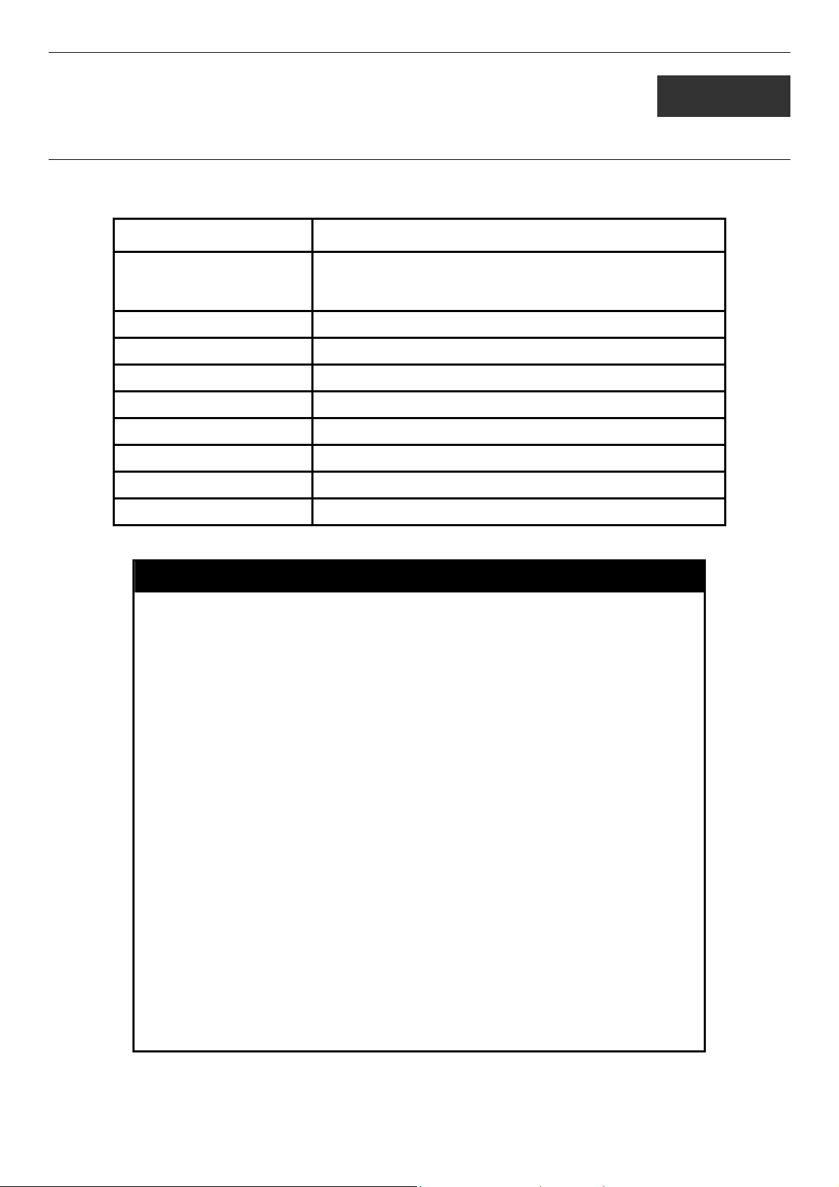
DES-3028 DES-3028P DES-3052 DES-3052P Layer 2 Fast Ethernet Switch CLI Reference Manual
9
SWITCH UTILITY COMMANDS
The switch utility commands in the Command Line Interface (CLI) are listed (along with the appropriate parameters) in the
following table.
Command Parameters
download [firmware_fromTFTP <ipaddr> <path_filename 64> {image_id
<int 1-2>} | cfg_fromTFTP <ipaddr> <path_filename 64>
{increment}]
config firmware image_id <int 1-2> [delete | boot_up]
show firmware information
show config [current_config | config_in_nvram]
upload [cfg_toTFTP | log_toTFTP] <ipaddr> <path_filename 64>
enable autoconfig
disable autoconfig
show autoconfig
ping <ipaddr> {times <value 1-255>} {timeout <sec 1-99>}
Each command is listed, in detail, in the following sections.
download
Purpose Used to download and install new firmware or a Switch
configuration file from a TFTP server.
Syntax
Description This command is used to download a new firmware or a Switch
Parameters
download [firmware_fromTFTP <ipaddr> <path_filename 64>
{image_id <int 1-2>} | cfg_fromTFTP <ipaddr> <path_filename
64> {increment}]
configuration file from a TFTP server.
firmware_fromTFTP − Download and install new firmware on the
Switch from a TFTP server.
cfg_fromTFTP − Download a switch configuration file from a TFTP
server.
<ipaddr> − The IP address of the TFTP server.
<path_filename> − The DOS path and filename of the firmware or
switch configuration file on the TFTP server. For example,
C:\3028.had.
image_id <int 1-2> - Specify the working section ID. The Switch can
hold two firmware versions for the user to select from, which are
specified by section ID.
increment − Allows the download of a partial switch configuration
file. This allows a file to be downloaded that will change only the
switch parameters explicitly stated in the configuration file. All other
switch parameters will remain unchanged.
Restrictions The TFTP server must be on the same IP subnet as the Switch.
Only administrator-level users can issue this command.
Example usage:
To download a configuration file:
49
Page 54

DES-3028 DES-3028P DES-3052 DES-3052P Layer 2 Fast Ethernet Switch CLI Reference Manual
DES-3028P:4#download cfg_fromTFTP 10.48.74.121 c:\cfg\setting.txt
Command: download cfg_fromTFTP 10.48.74.121 c:\cfg\setting.txt
Connecting to server................... Done.
Download configuration................. Done.
DES-3028P:4#
DES-3028P:4##------------------------------------------------------------------DES-3028P:4## DES-3028P Configuration
DES-3028P:4##
DES-3028P:4## Firmware: Build 1.00-B22
DES-3028P:4## Copyright(C) 2006-2009 D-Link Corporation. All rights reserved.
DES-3028P:4##------------------------------------------------------------------DES-3028P:4#
DES-3028P:4#
DES-3028P:4## BASIC
DES-3028P:4#
DES-3028P:4#config serial_port baud_rate 9600 auto_logout 10_minutes
Command: config serial_port baud_rate 9600 auto_logout 10_minutes
The download configuration command will initiate the loading of the various settings in the order listed in the configuration file.
When the file has been successfully loaded the message “End of configuration file for DES-3028P” appears followed by the
command prompt.
DES-3028P:4#disable authen_policy
Command: disable authen_policy
Success.
DES-3028P:4#
config firmware
Purpose Used to configure the firmware section image as a boot up section,
or to delete the firmware section
Syntax
Description This command is used to configure the firmware section image. The
Parameters image_id – Specifies the working section image. The Switch can
config firmware image_id <int 1-2> [delete | boot_up]
user may choose to remove the firmware section or use it as a boot
up section.
hold two firmware versions for the user to select from, which are
specified by image ID.
delete – Entering this parameter will delete the specified firmware
section image.
boot_up – Entering this parameter will specify the firmware image ID
as a boot up section image.
Restrictions Only administrator-level users can issue this command.
Example usage:
To configure firmware section image 1 as a boot up section:
50
Page 55

DES-3028 DES-3028P DES-3052 DES-3052P Layer 2 Fast Ethernet Switch CLI Reference Manual
DES-3028P:4# config firmware image_id 1 boot_up
Command: config firmware image_id 1 boot_up
Success.
DES-3028P:4#
show firmware information
Purpose Used to display the firmware section information.
Syntax
Description This command is used to display the firmware section information.
Parameters None.
Restrictions None
Example usage:
To display the current firmware information on the Switch:
DES-3028P:4#show firmware information
Command: show firmware information
ID Version Size(B) Update Time From User
-- -------- ------- ------------------- ------------------ --------------*1 1.00-B22 1532344 0000/00/00 00:03:03 10.24.22.5(CONSOLE) Anonymous
2 1.00-B05 1518404 0000/00/00 00:00:56 10.90.90.1(CONSOLE) Anonymous
'*' : Boot up firmware
(SSH) : Firmware update through SSH
(WEB) : Firmware update through WEB
(SIM) : Firmware update through Single IP Management
(SNMP) : Firmware update through SNMP
(TELNET) : Firmware update through TELNET
(CONSOLE) : Firmware update through CONSOLE
DES-3028P:4#
show firmware information
show config
Purpose Used to display the current or saved version of the configuration settings of the
switch.
Syntax
Description Use this command to display all the configuration settings that are saved to NV
show config [current_config | config_in_nvram]
RAM or display the configuration settings as they are currently configured. Use the
keyboard to list settings one line at a time (Enter), one page at a time (Space) or
view all (a).
The configuration settings are listed by category in the following order:
51
Page 56

DES-3028 DES-3028P DES-3052 DES-3052P Layer 2 Fast Ethernet Switch CLI Reference Manual
show config
1. Basic (serial port, Telnet and
web management status)
2. storm control
3. IP group management
4. Syslog
5. QoS
6. port mirroring
7. traffic segmentation
8. port
9. port lock
10. 8021x
11. SNMPv3
12. management (SNMP traps
RMON)
13. VLAN
14. FDB (forwarding data base)
15. MAC address table
notification
16. STP
17. SSH
18. SSL
19. ACL
20. SNTP
21. IP route
22. LACP
23. ARP
24. IP
25. IGMP snooping
26. access authentication control
(TACACS etc.)
27. PoE
28. Bandwidth
29. Time_range
30. GM
31. safeguard_engine
32. Banner_promp
33. SMTP
34. AAA
35. DHCP_Relay
Parameters current_config – Entering this parameter will display configurations entered without
being saved to NVRAM.
config_in_NVRAM - Entering this parameter will display configurations entered and
saved to NVRAM.
Restrictions None.
Example usage:
To view the current configuration settings:
DES-3028P:4#show config current_config
Command: show config current_config
#------------------------------------------------------------------------------------------# DES-3028P Configuration
#
# Firmware: Build 1.00-B22
# Copyright(C) 2006-2009 D-Link Corporation. All rights reserved.
#-------------------------------------------------------------------------------------------
# BASIC
config serial_port baud_rate 9600 auto_logout 10_minutes
# STORM
config traffic control 1 broadcast disable multicast disable dlf disable action
drop threshold 64 countdown 0 time_interval 5
config traffic control 2 broadcast disable multicast disable dlf disable action
drop threshold 64 countdown 0 time_interval 5
config traffic control 3 broadcast disable multicast disable dlf disable action
drop threshold 64 countdown 0 time_interval 5
config traffic control 4 broadcast disable multicast disable dlf disable action
drop threshold 64 countdown 0 time_interval 5
CTRL+C ESC q Quit SPACE n Next Page ENTER Next Entry a All
52
Page 57

DES-3028 DES-3028P DES-3052 DES-3052P Layer 2 Fast Ethernet Switch CLI Reference Manual
upload
Purpose Used to upload the current switch settings or the switch history log to a
TFTP.
Syntax
Description This command is used to upload either the Switch’s current settings or
Parameters
Restrictions The TFTP server must be on the same IP subnet as the Switch. Only
Example usage:
To upload a configuration file:
DES-3028P:4#upload cfg_toTFTP 10.48.74.121 c:\cfg\log.txt
Command: upload cfg_toTFTP 10.48.74.121 c:\cfg\log.txt
Connecting to server................... Done.
Upload configuration...................Done.
DES-3028P:4#
upload [cfg_toTFTP | log_toTFTP] <ipaddr> <path_filename 64>
the Switch’s history log to a TFTP server.
cfg_toTFTP − Specifies that the Switch’s current settings will be
uploaded to the TFTP server.
log_toTFTP − Specifies that the switch history log will be uploaded to
the TFTP server.
<ipaddr> − The IP address of the TFTP server. The TFTP server must
be on the same IP subnet as the Switch.
<path_filename 64> − Specifies the location of the Switch
configuration file on the TFTP server. This file will be replaced by the
uploaded file from the Switch.
administrator-level users can issue this command.
enable autoconfig
Purpose Used to activate the autoconfiguration function for the Switch. This will load a
previously saved configuration file for current use.
Syntax
Description When autoconfig is enabled on the Switch, the DHCP reply will contain a
Parameters None.
Restrictions When autoconfig is enabled, the Switch becomes a DHCP client automatically
enable autoconfig
configuration file and path name. It will then request the file from the TFTP server
specified in the reply. When autoconfig is enabled, the ipif settings will
automatically become DHCP client.
(same as: config ipif System dhcp). The DHCP server must have the TFTP
server IP address and configuration file name, and be configured to deliver this
information in the data field of the DHCP reply packet. The TFTP server must be
running and have the requested configuration file in its base directory when the
request is received from the Switch. Consult the DHCP server and TFTP server
software instructions for information on loading a configuration file.
If the Switch is unable to complete the autoconfiguration process the previously
saved local configuration file present in Switch memory will be loaded.
53
Page 58

DES-3028 DES-3028P DES-3052 DES-3052P Layer 2 Fast Ethernet Switch CLI Reference Manual
NOTE: Dual-purpose (DHCP/TFTP) server utility software may require entry of the
configuration file name and path within the user interface. Alternatively, the DHCP software
may require creating a separate ext file with the configuration file name and path in a specific
directory on the server. Consult the documentation for the DCHP server software if users are
unsure.
Example usage:
To enable autoconfiguration on the Switch:
DES-3028P:4#enable autoconfig
Command: enable autoconfig
Success.
DES-3028P:4#
When autoconfig is enabled and the Switch is rebooted, the normal login screen will appear for a few moments while the
autoconfig request (i.e. download configuration) is initiated. The console will then display the configuration parameters as they
are loaded from the configuration file specified in the DHCP or TFTP server. This is exactly the same as using a download
configuration command. After the entire Switch configuration is loaded, the Switch will automatically “logout” the server. The
configuration settings will be saved automatically and become the active configuration.
Upon booting up the autoconfig process is initiated, the console screen will appear similar to the example below. The
configuration settings will be loaded in normal order.
DES-3028P Fast Ethernet Switch Command Line Interface
Firmware: Build 1.00-B22
Copyright(C) 2006-2009 D-Link Corporation. All rights reserved.
DES-3028P:4#
DES-3028P:4#
DES-3028P:4#download cfg_fromTFTP 10.41.44.44 c:\cfg\setting.txt
Command: download cfg_fromTFTP 10.41.44.44 c:\cfg\setting.txt
Connecting to server................... Done.
Download configuration................. Done.
The very end of the autoconfig process appears like this:
Success.
DES-3028P:4#
DES-3028P:4## ROUTE
DES-3028P:4#
DES-3028P:4#
DES-3028P:4##------------------------------------------------------------------------------------DES-3028P:4## End of configuration file for DES-3028P
DES-3028P:4##------------------------------------------------------------------------------------DES-3028P:4#
DES-3028P:4#
NOTE: With autoconfig enabled, the Switch ipif settings now define the Switch as a
DHCP client. Use the show switch command to display the new IP settings status.
54
Page 59

DES-3028 DES-3028P DES-3052 DES-3052P Layer 2 Fast Ethernet Switch CLI Reference Manual
disable autoconfig
Purpose Use this to deactivate autoconfiguration from DHCP.
Syntax
Description This instructs the Switch not to accept autoconfiguration instruction from the
Parameters None.
Restrictions None.
Example usage:
To stop the autoconfiguration function:
DES-3028P:4#disable autoconfig
Command: disable autoconfig
Success.
DES-3028P:4#
disable autoconfig
DHCP server. This does not change the IP settings of the Switch. The ipif
settings will continue as DHCP client until changed with the config ipif
command.
show autoconfig
Purpose Used to display the current autoconfig status of the Switch.
Syntax
Description This command will list the current status of the autoconfiguration
Parameters None.
Restrictions None.
Example usage:
To display the autoconfig status:
DES-3028P:4#show autoconfig
Command: show autoconfig
Autoconfig State: Disabled
DES-3028P:4#
show autoconfig
function.
55
Page 60

DES-3028 DES-3028P DES-3052 DES-3052P Layer 2 Fast Ethernet Switch CLI Reference Manual
ping
Purpose Used to test the connectivity between network devices.
Example usage:
To ping the IP address 10.48.74.121 four times:
Syntax
Description The ping command sends Internet Control Message Protocol (ICMP)
Parameters <ipaddr> - Specifies the IP address of the host.
Restrictions None.
DES-3028P:4#ping 10.48.74.121 times 4
Command: ping 10.48.74.121
Reply from 10.48.74.121, time<10ms
Reply from 10.48.74.121, time<10ms
Reply from 10.48.74.121, time<10ms
Reply from 10.48.74.121, time<10ms
Ping statistics for 10.48.74.121
Packets: Sent =4, Received =4, Lost =0
DES-3028P:4#
ping <ipaddr> {times <value 1-255>} {timeout <sec 1-99>}
echo messages to a remote IP address. The remote IP address will
then “echo” or return the message. This is used to confirm
connectivity between the Switch and the remote device.
times <value 1-255> - The number of individual ICMP echo
messages to be sent. A value of 0 will send an infinite ICMP echo
messages. The maximum value is 255. The default is 0.
timeout <sec 1-99> - Defines the time-out period while waiting for a
response from the remote device. A value of 1 to 99 seconds can be
specified. The default is 1 second
56
Page 61

DES-3028 DES-3028P DES-3052 DES-3052P Layer 2 Fast Ethernet Switch CLI Reference Manual
10
NETWORK MONITORING COMMANDS
The network monitoring commands in the Command Line Interface (CLI) are listed (along with the appropriate parameters) in the
following table.
Command Parameters
show packet ports <portlist>
show error ports <portlist>
show utilization [cpu | ports {<portlist>}]
clear counters ports <portlist>
clear log
show log index <value_list X-Y>
enable syslog
disable syslog
show syslog
create syslog host <index 1-4> ipaddress <ipaddr> {severity [informational | warning |
all] | facility [local0 | local1 | local2 | local3 | local4 | local5 | local6 |
local7] | udp_port <udp_port_number>| state [enable | disable]
config syslog host [all | <index 1-4>] {severity [informational | warning | all] | facility
[local0 | local1 | local2 | local3 | local4 | local5 | local6 | local7] |
udp_port <udp_port_number> | ipaddress <ipaddr> | state [enable
| disable]}
delete syslog host [<index 1-4> | all]
show syslog host <index 1-4>
config log_save_timing [time_interval <min 1-65535> | on_demand | log_trigger]
show log_save_timing
Each command is listed, in detail, in the following sections.
show packet ports
Purpose Used to display statistics about the packets sent and received by the
Switch.
Syntax
Description This command is used to display statistics about packets sent and
show packet ports <portlist>
received by ports specified in the <portlist>.
Example usage:
To display the packets analysis for port 7 of module 2:
Parameters
Restrictions None.
<portlist> − Specifies a port or range of ports to be displayed.
57
Page 62

DES-3028 DES-3028P DES-3052 DES-3052P Layer 2 Fast Ethernet Switch CLI Reference Manual
DES-3028P:4#show packet port 2
Command: show packet port 2
Port number : 2
Frame Size Frame Counts Frame/sec Frame Type Total Total/sec
------------ ------------ ---------- ---------- ------- --------64 3275 10 RX Bytes 408973 1657
65-127 755 10 RX Frames 395 19
128-255 316 1
256-511 145 0 TX Bytes 7918 178
512-1023 15 0 TX Frames 111 2
1024-1518 0 0
Unicast RX 152 1
Multicast RX 557 2
Broadcast RX 3686 16
CTRL+C ESC q Quit SPACE n Next Page p Previous Page r Refresh
show error ports
Example usage:
To display the errors of the port 3 of module 1:
Purpose Used to display the error statistics for a range of ports.
Syntax
Description This command will display all of the packet error statistics collected
Parameters
Restrictions None.
DES-3028P:4#show error ports 3
Command: show error ports 3
Port number : 3
RX Frames TX Frames
--------------- ---------------CRC Error 19 Excessive Deferral 0
Undersize 0 CRC Error 0
Oversize 0 Late Collision 0
Fragment 0 Excessive Collision 0
Jabber 11 Single Collision 0
Drop Pkts 20837 Collision 0
CTRL+C ESC q Quit SPACE n Next Page p Previous Page r Refresh
show error ports <portlist>
and logged by the Switch for a given port list.
<portlist> − Specifies a port or range of ports to be displayed.
58
Page 63

DES-3028 DES-3028P DES-3052 DES-3052P Layer 2 Fast Ethernet Switch CLI Reference Manual
show utilization
Purpose Used to display real-time port and CPU utilization statistics.
Example usage:
To display the port utilization statistics:
Syntax
Description This command will display the real-time port and CPU utilization
Parameters cpu – Entering this parameter will display the current cpu utilization
Restrictions None.
DES-3028P:4#show utilization ports
Command: show utilization ports
Port TX/sec RX/sec Util Port TX/sec RX/sec Util
------ ---------- ---------- ---- ------ ---------- ---------- ---1 0 0 0 22 0 0 0
2 0 0 0 23 0 0 0
3 0 0 0 24 0 0 0
4 0 0 0 25 0 26 1
5 0 0 0 26 0 0 0
6 0 0 0 27 0 0 0
7 0 0 0 28 0 0 0
8 0 0 0
9 0 0 0
10 0 0 0
11 0 0 0
12 0 0 0
13 0 0 0
14 0 0 0
15 0 0 0
16 0 0 0
17 0 0 0
18 0 0 0
19 0 0 0
20 0 0 0
21 0 0 0
CTRL+C ESC q Quit SPACE n Next Page p Previous Page r Refresh
show utilization [cpu | ports {<portlist>}]
statistics for the Switch.
of the Switch.
ports - Entering this parameter will display the current port
utilization of the Switch.
<portlist> - Specifies a port or range of ports to be
displayed.
To display the current CPU utilization:
DES-3028P:4#show utilization cpu
Command: show utilization cpu
CPU utilization :
-------------------------------------------------------------------------------------------Five seconds - 15% One minute - 25% Five minutes - 14%
DES-3028P:4#
59
Page 64

DES-3028 DES-3028P DES-3052 DES-3052P Layer 2 Fast Ethernet Switch CLI Reference Manual
clear counters
Purpose Used to clear the Switch’s statistics counters.
Example usage:
To clear the counters:
Syntax
Description This command will clear the counters used by the Switch to compile
Parameters
Restrictions Only administrator-level users can issue this command.
DES-3028P:4#clear counters ports 2-9
Command: clear counters ports 2-9
Success.
DES-3028P:4#
clear counters {ports <portlist>}
statistics.
<portlist> − Specifies a port or range of ports to be displayed.
clear log
Purpose Used to clear the Switch’s history log.
Syntax
clear log
Example usage:
To clear the log information:
Description This command will clear the Switch’s history log.
Parameters None.
Restrictions Only administrator-level users can issue this command.
DES-3028P:4#clear log
Command: clear log
Success.
DES-3028P:4#
show log
Purpose Used to display the switch history log.
Syntax
Description This command will display the contents of the Switch’s history log.
Parameters
show log {index <value_list X-Y>}
index <value_list X-Y>
beginning and ending at the value specified by the user in the
<value_list X-Y> field.
If no parameter is specified, all history log entries will be displayed.
−
This command will display the history log,
Example usage:
To display the switch history log:
Restrictions None.
60
Page 65

DES-3028 DES-3028P DES-3052 DES-3052P Layer 2 Fast Ethernet Switch CLI Reference Manual
DES-3028P:4#show log index 1-5
Command: show log index 1-5
Index Data Time Log Text
----- ---------------------------- ------------------------------------------------------------------------------------5 00000-00-00 01:01:09 Successful login through Console (Username: Anonymous)
4 00000-00-00 00:00:14 System started up
3 00000-00-00 00:00:06 Port 1 link up, 100Mbps FULL duplex
2 00000-00-00 00:00:01 Spanning Tree Protocol is disabled
1 00000-00-00 00:06:31 Configuration saved to flash (Username: Anonymous)
DES-3028P:4#
enable syslog
Purpose Used to enable the system log to be sent to a remote host.
Example usage:
To the syslog function on the Switch:
Syntax
Description The enable syslog command enables the system log to be sent to
Parameters None.
Restrictions Only administrator-level users can issue this command.
DES-3028P:4#enable syslog
Command: enable syslog
Success.
DES-3028P:4#
enable syslog
a remote host.
disable syslog
Purpose
Syntax disable syslog
Description
Used to enable the system log to be sent to a remote host.
The disable syslog command enables the system log to be sent to a
remote host.
Example usage:
To disable the syslog function on the Switch:
Parameters
Restrictions
None.
Only administrator-level users can issue this command.
DES-3028P:4#disable syslog
Command: disable syslog
Success.
DES-3028P:4#
61
Page 66

DES-3028 DES-3028P DES-3052 DES-3052P Layer 2 Fast Ethernet Switch CLI Reference Manual
show syslog
Purpose
Syntax show syslog
Description
Parameters
Restrictions
Example usage:
To display the current status of the syslog function:
DES-3028P:4#show syslog
Command: show syslog
Syslog Global State: Enabled
DES-3028P:4#
Used to display the syslog protocol status as enabled or disabled.
The show syslog command displays the syslog status as enabled or
disabled.
None.
None.
create syslog host
Purpose
Syntax create syslog host <index 1-4> ipaddress <ipaddr> {severity [informational | warning |
Used to create a new syslog host.
all] | facility [local0 | local1 | local2 | local3 | local4 | local5 | local6 | local7] | udp_port
<udp_port_number> | state [enable | disable]
Description
Parameters
The create syslog host command is used to create a new syslog host.
<index 1-4> − Specifies that the command will be applied to an index of hosts. There are
four available indexes, numbered 1 through 4.
ipaddress <ipaddr> − Specifies the IP address of the remote host where syslog messages
will be sent.
severity − Severity level indicator. These are described in the following:
Bold font indicates that the corresponding severity level is currently supported on the
Switch.
Numerical Severity
Code
0 Emergency: system is unusable
1 Alert: action must be taken immediately
2 Critical: critical conditions
3 Error: error conditions
4 Warning: warning conditions
5 Notice: normal but significant condition
6 Informational: informational messages
7 Debug: debug-level messages
Numerical Facility
Code
62
Page 67

DES-3028 DES-3028P DES-3052 DES-3052P Layer 2 Fast Ethernet Switch CLI Reference Manual
create syslog host
0 kernel messages
1 user-level messages
2 mail system
3 system daemons
4 security/authorization messages
5 messages generated internally by syslog
6 line printer subsystem
7 network news subsystem
8 UUCP subsystem
9 clock daemon
10 security/authorization messages
11 FTP daemon
12 NTP subsystem
13 log audit
14 log alert
15 clock daemon
16 local use 0 (local0)
17 local use 1 (local1)
18 local use 2 (local2)
19 local use 3 (local3)
20 local use 4 (local4)
21 local use 5 (local5)
22 local use 6 (local6)
23 local use 7 (local7)
local0 − Specifies that local use 0 messages will be sent to the remote host. This
corresponds to number 16 from the list above.
local1 − Specifies that local use 1 messages will be sent to the remote host. This
corresponds to number 17 from the list above.
local2 − Specifies that local use 2 messages will be sent to the remote host. This
corresponds to number 18 from the list above.
local3 − Specifies that local use 3 messages will be sent to the remote host. This
corresponds to number 19 from the list above.
local4 − Specifies that local use 4 messages will be sent to the remote host. This
corresponds to number 20 from the list above.
local5 − Specifies that local use 5 messages will be sent to the remote host. This
corresponds to number 21 from the list above.
local6 − Specifies that local use 6 messages will be sent to the remote host. This
corresponds to number 22 from the list above.
local7 − Specifies that local use 7 messages will be sent to the remote host. This
corresponds to number 23 from the list above.
udp_port <udp_port_number> − Specifies the UDP port number that the syslog protocol will
use to send messages to the remote host.
state [enable | disable] − Allows the sending of syslog messages to the remote host,
specified above, to be enabled and disabled.
Restrictions
Example usage:
To create syslog host:
Only administrator-level users can issue this command.
DES-3028P:4#create syslog host 1 severity all facility local0
Command: create syslog host 1 severity all facility local0
Success.
DES-3028P:4#
63
Page 68

DES-3028 DES-3028P DES-3052 DES-3052P Layer 2 Fast Ethernet Switch CLI Reference Manual
config syslog host
Purpose
Syntax config syslog host [all | <index 1-4>] {severity [informational | warning | all] | facility
Description
Parameters
Used to configure the syslog protocol to send system log data to a remote host.
[local0 | local1 | local2 | local3 | local4 | local5 | local6 | local7] | udp_port
<udp_port_number> | ipaddress <ipaddr> | state [enable | disable]
The config syslog host command is used to configure the syslog protocol to send system
log information to a remote host.
<index 1-4> − Specifies that the command will be applied to an index of hosts. There are
four available indexes, numbered 1 through 4.
ipaddress <ipaddr> − Specifies the IP address of the remote host where syslog messages
will be sent.
severity − Severity level indicator. These are described in the following:
Bold font indicates that the corresponding severity level is currently supported on the
Switch.
Numerical Severity
Code
0 Emergency: system is unusable
1 Alert: action must be taken immediately
2 Critical: critical conditions
3 Error: error conditions
4 Warning: warning conditions
5 Notice: normal but significant condition
6 Informational: informational messages
7 Debug: debug-level messages
informational − Specifies that informational messages will be sent to the remote host. This
corresponds to number 6 from the list above.
warning − Specifies that warning messages will be sent to the remote host. This
corresponds to number 4 from the list above.
all − Specifies that all of the currently supported syslog messages that are generated by the
Switch will be sent to the remote host.
facility − Some of the operating system daemons and processes have been assigned
Facility values. Processes and daemons that have not been explicitly assigned a Facility
may use any of the "local use" facilities or they may use the "user-level" Facility. Those
Facilities that have been designated are shown in the following: Bold font indicates the
facility values the Switch currently supports.
64
Page 69

DES-3028 DES-3028P DES-3052 DES-3052P Layer 2 Fast Ethernet Switch CLI Reference Manual
Parameters
Numerical Facility
Code
0 kernel messages
1 user-level messages
2 mail system
3 system daemons
4 security/authorization messages
5 messages generated internally by syslog
6 line printer subsystem
7 network news subsystem
8 UUCP subsystem
9 clock daemon
10 security/authorization messages
11 FTP daemon
12 NTP subsystem
13 log audit
14 log alert
15 clock daemon
16 local use 0 (local0)
17 local use 1 (local1)
18 local use 2 (local2)
19 local use 3 (local3)
20 local use 4 (local4)
21 local use 5 (local5)
22 local use 6 (local6)
23 local use 7 (local7)
Parameters
local0 − Specifies that local use 0 messages will be sent to the remote host. This
corresponds to number 16 from the list above.
local1 − Specifies that local use 1 messages will be sent to the remote host. This
corresponds to number 17 from the list above.
local2 − Specifies that local use 2 messages will be sent to the remote host. This
corresponds to number 18 from the list above.
local3 − Specifies that local use 3 messages will be sent to the remote host. This
corresponds to number 19 from the list above.
local4 − Specifies that local use 4 messages will be sent to the remote host. This
corresponds to number 20 from the list above.
local5 − Specifies that local use 5 messages will be sent to the remote host. This
corresponds to number 21 from the list above.
local6 − Specifies that local use 6 messages will be sent to the remote host. This
corresponds to number 22 from the list above.
local7 − Specifies that local use 7 messages will be sent to the remote host. This
corresponds to number 23 from the list above.
udp_port <udp_port_number> − Specifies the UDP port number that the syslog protocol will
use to send messages to the remote host.
state [enable | disable] − Allows the sending of syslog messages to the remote host,
specified above, to be enabled and disabled.
Restrictions
Example usage:
To configure a Syslog host:
Only administrator-level users can issue this command.
65
Page 70

DES-3028 DES-3028P DES-3052 DES-3052P Layer 2 Fast Ethernet Switch CLI Reference Manual
Example usage:
To configure a Syslog host for all hosts:
delete syslog host
DES-3028P:4#config syslog host 1 severity all facility local0
Command: config syslog host all severity all facility local0
Success.
DES-3028P:4#
DES-3028P:4#config syslog host all severity all facility local0
Command: config syslog host all severity all facility local0
Success.
DES-3028P:4#
Purpose
Syntax delete syslog host [<index 1-4> | all]
Description
Parameters
Restrictions
Example usage:
To delete a previously configured syslog host:
Used to remove a syslog host that has been previously configured, from the
Switch.
The delete syslog host command is used to remove a syslog host that has
been previously configured from the Switch.
<index 1-4> − Specifies that the command will be applied to an index of hosts.
There are four available indexes, numbered 1 through 4.
all − Specifies that the command will be applied to all hosts.
Only administrator-level users can issue this command.
DES-3028P:4#delete syslog host 4
Command: delete syslog host 4
Success.
DES-3028P:4#
Example usage:
To show Syslog host information:
show syslog host
Purpose
Syntax show syslog host {<index 1-4>}
Description
Parameters
Restrictions
Used to display the syslog hosts currently configured on the Switch.
The show syslog host command is used to display the syslog
hosts that are currently configured on the Switch.
<index 1-4> − Specifies that the command will be applied to an
index of hosts. There are four available indexes, numbered 1
through 4.
None.
66
Page 71

DES-3028 DES-3028P DES-3052 DES-3052P Layer 2 Fast Ethernet Switch CLI Reference Manual
DES-3028P:4#show syslog host
Command: show syslog host
Syslog Global State: Disabled
Host Id Host IP Address Severity Facility UDP port Status
------- --------------- -------------- -------- -------- -------1 10.1.1.2 All Local0 514 Disabled
2 10.40.2.3 All Local0 514 Disabled
3 10.21.13.1 All Local0 514 Disabled
Total Entries : 3
DES-3028P:4#
config log_save_timing
Purpose Used to configure the method of saving log files to the switch’s flash
memory.
Example usage:
To configure the time interval as every 30 minutes for saving log files:
Syntax
Description The config log_save_timing command allows the user to
Parameters time_interval <min 1-65535> - Use this parameter to configure the
Restrictions Only administrator-level users can issue this command.
DES-3028P:4#config log_save_timing time_interval 30
Command: config log_save_timing time_interval 30
Success.
DES-3028P:4#
config log_save_timing [time_interval <min 1-65535> |
on_demand | log_trigger]
configure the time method used in saving log files to the switch’s
flash memory.
time interval that will be implemented for saving log files. The log
files will be save every x number of minutes that are configured
here.
on_demand - Users who choose this method will only save log files
when they manually tell the Switch to do so, using the save or save
log command.
log_trigger - Users who choose this method will have log files saved
to the Switch every time a log event occurs on the Switch.
show log_save_timing
Purpose Used to display the method configured for saving log files to the
switch’s flash memory.
Syntax
Description The show log_save_timing command allows the user to view the
Parameters None.
Restrictions None.
show log_save_timing
time method configured for saving log files to the switch’s flash
memory.
67
Page 72

DES-3028 DES-3028P DES-3052 DES-3052P Layer 2 Fast Ethernet Switch CLI Reference Manual
Example usage:
To display the time interval for saving log files:
DES-3028P:4#show log_save_timing
Command: show log_save_timing
Saving log method: time_interval
Interval : 30
DES-3028P:4#
68
Page 73

DES-3028 DES-3028P DES-3052 DES-3052P Layer 2 Fast Ethernet Switch CLI Reference Manual
11
MULTIPLE SPANNING TREE PROTOCOL (MSTP) COMMANDS
This Switch supports three versions of the Spanning Tree Protocol; 802.1d STP, 802.1w Rapid STP and 802.1s MSTP. Multiple
Spanning Tree Protocol, or MSTP, is a standard defined by the IEEE community that allows multiple VLANs to be mapped to a
single spanning tree instance, which will provide multiple pathways across the network. Therefore, these MSTP configurations
will balance the traffic load, preventing wide scale disruptions when a single spanning tree instance fails. This will allow for faster
convergences of new topologies for the failed instance. Frames designated for these VLANs will be processed quickly and
completely throughout interconnected bridges utilizing either of the three spanning tree protocols (STP, RSTP or MSTP). This
protocol will also tag BDPU packets so receiving devices can distinguish spanning tree instances, spanning tree regions and the
VLANs associated with them. These instances will be classified by an instance_id. MSTP will connect multiple spanning trees
with a Common and Internal Spanning Tree (CIST). The CIST will automatically determine each MSTP region, its maximum
possible extent and will appear as one virtual bridge that runs a single spanning tree. Consequentially, frames assigned to different
VLANs will follow different data routes within administratively established regions on the network, continuing to allow simple
and full processing of frames, regardless of administrative errors in defining VLANs and their respective spanning trees. Each
switch utilizing the MSTP on a network will have a single MSTP configuration that will have the following three attributes:
a) A configuration name defined by an alphanumeric string of up to 32 characters (defined in the config stp mst_config_id
command as name <string>).
b) A configuration revision number (named here as a revision_level) and;
c) A 4094 element table (defined here as a vid_range) which will associate each of the possible 4094 VLANs supported by
the Switch for a given instance.
To utilize the MSTP function on the Switch, three steps need to be taken:
a) The Switch must be set to the MSTP setting (config stp version)
b) The correct spanning tree priority for the MSTP instance must be entered (config stp priority).
c) VLANs that will be shared must be added to the MSTP Instance ID (config stp instance_id).
The Multiple Spanning Tree Protocol commands in the Command Line Interface (CLI) are listed (along with the appropriate
parameters) in the following table.
Command Parameters
enable stp
disable stp
config stp version [mstp | rstp | stp]
config stp {maxage <value 6-40> | maxhops <value 1-20> | hellotime <value 1-10> |
forwarddelay <value 4-30>| txholdcount <value 1-10> | fbpdu [enable | disable] |
lbd [enable | disable] | lbd_recover_timer [0 | <value 60-1000000>]}
config stp ports <portlist> {externalCost [auto | <value 1-200000000>] | hellotime <value 1-10> |
migrate [yes | no] | edge [true | false] | p2p [true | false | auto] | state [enable |
disable] | lbd [enable | disable] | fbpdu [enable |disable]}
create stp instance_id <value 1-4>
config stp instance _id <value 1-4> [add_vlan | remove_vlan] <vidlist>
delete stp instance_id <value 1-4>
config stp priority <value 0-61440> instance_id <value 0-4>
config stp
mst_config_id
config stp mst_ports <portlist> instance_id <value 0-4> {internalCost [auto | value 1-200000000] |
{revision_level <int 0-65535> | name <string>}
priority <value 0-240>}
show stp
show stp ports {<portlist>}
69
Page 74

DES-3028 DES-3028P DES-3052 DES-3052P Layer 2 Fast Ethernet Switch CLI Reference Manual
Command Parameters
show stp instance {<value 0-4>}
show stp mst_config id
Each command is listed, in detail, in the following sections.
enable stp
Purpose
Syntax enable stp
Description
Parameters
Restrictions
Example usage:
To enable STP, globally, on the Switch:
disable stp
Purpose
Syntax disable stp
Used to globally enable STP on the Switch.
This command allows the Spanning Tree Protocol to be globally
enabled on the Switch.
None.
Only administrator-level users can issue this command.
DES-3028P:4#enable stp
Command: enable stp
Success.
DES-3028P:4#
Used to globally disable STP on the Switch.
Description
Parameters
Restrictions
Example usage:
To disable STP on the Switch:
config stp version
Purpose
Syntax config stp version [mstp | rstp | stp]
Description
This command allows the Spanning Tree Protocol to be globally
disabled on the Switch.
None.
Only administrator-level users can issue this command.
DES-3028P:4#disable stp
Command: disable stp
Success.
DES-3028P:4#
Used to globally set the version of STP on the Switch.
This command allows the user to choose the version of the spanning tree
to be implemented on the Switch.
Parameters
mstp – Selecting this parameter will set the Multiple Spanning Tree
Protocol (MSTP) globally on the Switch.
rstp - Selecting this parameter will set the Rapid Spanning Tree Protocol
70
Page 75

DES-3028 DES-3028P DES-3052 DES-3052P Layer 2 Fast Ethernet Switch CLI Reference Manual
config stp version
(RSTP) globally on the Switch.
stp - Selecting this parameter will set the Spanning Tree Protocol (STP)
globally on the Switch.
Restrictions
Example usage:
To set the Switch globally for the Multiple Spanning Tree Protocol (MSTP):
DES-3028P:4#config stp version mstp
Command: config stp version mstp
Success.
DES-3028P:4#
Only administrator-level users can issue this command.
config stp
Purpose
Syntax config stp {maxage <value 6-40> | maxhops <value 1-20> | hellotime
Description
Used to setup STP, RSTP and MSTP on the Switch.
<value 1-10> | forwarddelay <value 4-30>| txholdcount <value 1-10> |
fbpdu [enable | disable] | lbd [enable | disable] | lbd_recover_timer [0
| <value 60-1000000>]}
This command is used to setup the Spanning Tree Protocol (STP) for the
entire Switch. All commands here will be implemented for the STP
version that is currently set on the Switch.
Parameters
maxage <value 6-40> − This value may be set to ensure that old
information does not endlessly circulate through redundant paths in the
network, preventing the effective propagation of the new information. Set
by the Root Bridge, this value will aid in determining that the Switch has
spanning tree configuration values consistent with other devices on the
bridged LAN. If the value ages out and a BPDU has still not been
received from the Root Bridge, the Switch will start sending its own BPDU
to all other switches for permission to become the Root Bridge. If it turns
out that your switch has the lowest Bridge Identifier, it will become the
Root Bridge. The user may choose a time between 6 and 40 seconds.
The default value is 20.
maxhops <value 1-20> - The number of hops between devices in a
spanning tree region before the BPDU (bridge protocol data unit) packet
sent by the Switch will be discarded. Each switch on the hop count will
reduce the hop count by one until the value reaches zero. The Switch will
then discard the BDPU packet and the information held for the port will
age out. The user may set a hop count from 1 to 20. The default is 20.
hellotime <value 1-10> − The user may set the time interval between
transmission of configuration messages by the root device, thus stating
that the Switch is still functioning. A time between 1 and 10 seconds may
be chosen, with a default setting of 2 seconds.
NOTE:
and therefore, the hellotime must be set using the
configure stp ports command for switches utilizing the
Multiple Spanning Tree Protocol.
In MSTP, the spanning tree is configured by port
forwarddelay <value 4-30> − The maximum amount of time (in seconds)
that the root device will wait before changing states. The user may
choose a time between 4 and 30 seconds. The default is 15 seconds.
txholdcount <1-10> - The maximum number of BPDU Hello packets
transmitted per interval. Default value = 3.
71
Page 76

DES-3028 DES-3028P DES-3052 DES-3052P Layer 2 Fast Ethernet Switch CLI Reference Manual
config stp
fbpdu [enable | disable] − Allows the forwarding of STP BPDU packets
from other network devices when STP is disabled on the Switch. The
default is enable.
lbd [enable | disable] – Enabling this feature temporarily block STP on the
Switch when a BPDU packet has been looped back to the switch. When
the Switch detects its own BPDU packet coming back, it signifies a loop
on the network. STP will automatically be blocked and an alert will be
sent to the administrator. The LBD STP port will restart (change to
discarding state) when the LBD Recover Time times out. The default is
enabled.
lbd_recover_timer [0 | <value 60-1000000>] - This field will set the time
the STP port will wait before recovering the STP state set. 0 will denote
that the LBD will never time out or restart until the administrator
personally changes it. The user may also set a time between 60 and
1000000 seconds. The default is 60 seconds.
Restrictions
Example usage:
To configure STP with maxage 18 and maxhops of 15:
config stp ports
Purpose
Syntax config stp ports <portlist> {externalCost [auto | <value 1-200000000>] |
Description
Parameters
Only administrator-level users can issue this command.
DES-3028P:4#config stp maxage 18 maxhops 15
Command: config stp maxage 18 maxhops 15
Success.
DES-3028P:4#
Used to setup STP on the port level.
hellotime <value 1-10> | migrate [yes | no] edge [true | false] | p2p [true | false
| auto] | state [enable | disable] | lbd [enable | disable] | fbpdu [enable |
disable]}
This command is used to create and configure STP for a group of ports.
<portlist> − Specifies a range of ports to be configured.
externalCost − This defines a metric that indicates the relative cost of forwarding
packets to the specified port list. Port cost can be set automatically or as a metric
value. The default value is auto.
1. auto – Setting this parameter for the external cost will automatically set the
speed for forwarding packets to the specified port(s) in the list for optimal
efficiency. Default port cost: 100Mbps port = 200000. Gigabit port = 20000.
2. <value 1-200000000> - Define a value between 1 and 200000000 to
determine the external cost. The lower the number, the greater the
probability the port will be chosen to forward packets.
hellotime <value 1-10> − The time interval between transmission of configuration
messages by the designated port, to other devices on the bridged LAN, thus
stating that the Switch is still functioning. The user may choose a time between 1
and 10 seconds. The default is 2 seconds.
migrate [yes | no] – Setting this parameter as “yes” will set the ports to send out
BDPU packets to other bridges, requesting information on their STP setting If the
Switch is configured for RSTP, the port will be capable to migrate from 802.1d STP
to 802.1w RSTP. If the Switch is configured for MSTP, the port is capable of
migrating from 802.1d STP to 802.1s MSTP. RSTP and MSTP can coexist with
standard STP, however the benefits of RSTP and MSTP are not realized on a port
72
Page 77

DES-3028 DES-3028P DES-3052 DES-3052P Layer 2 Fast Ethernet Switch CLI Reference Manual
config stp ports
where an 802.1d network connects to an 802.1w or 802.1s enabled network.
Migration should be set as yes on ports connected to network stations or segments
that are capable of being upgraded to 802.1w RSTP or 802.1s MSTP on all or
some portion of the segment.
edge [true | false] – true designates the port as an edge port. Edge ports cannot
create loops, however an edge port can lose edge port status if a topology change
creates a potential for a loop. An edge port normally should not receive BPDU
packets. If a BPDU packet is received it automatically loses edge port status. false
indicates that the port does not have edge port status.
p2p [true | false | auto] – true indicates a point-to-point (P2P) shared link. P2P
ports are similar to edge ports however they are restricted in that a P2P port must
operate in full-duplex. Like edge ports, P2P ports transition to a forwarding state
rapidly thus benefiting from RSTP. A p2p value of false indicates that the port
cannot have p2p status. Auto allows the port to have p2p status whenever possible
and operate as if the p2p status were true. If the port cannot maintain this status
(for example if the port is forced to half-duplex operation) the p2p status changes
to operate as if the p2p value were false. The default setting for this parameter is
auto.
state [enable | disable] − Allows STP to be enabled or disabled for the ports
specified in the port list. The default is enable.
lbd [enable | disable] - Used to enable or disable the loop-back detection function
on the switch for the ports configured above in the config stp command.
fbpdu [enable | disable] − When enabled, this allows the forwarding of STP BPDU
packets from other network devices when STP is disabled in the specified ports. If
users want to enable Forwarding BPDU on a per port basis, the following settings
must first be in effect: 1. STP must be globally disabled and 2. Forwarding BPDU
must be globally enabled. To globally disable STP, use the disable stp command,
to globally enable fbpdu, use the config stp command. The default is disable.
Restrictions
Only administrator-level users can issue this command.
73
Page 78

DES-3028 DES-3028P DES-3052 DES-3052P Layer 2 Fast Ethernet Switch CLI Reference Manual
Example usage:
To configure STP with path cost 19, hellotime set to 5 seconds, migration enable, and state enable for ports 1-5 of
module 1.
DES-3028P:4#config stp ports 1-5 externalCost 19 hellotime 5 migrate yes state enable
Command: config stp ports 1-5 externalCost 19 hellotime 5 migrate yes state enable
Success.
DES-3028P:4#
create stp instance_id
Purpose
Syntax create stp instance_id <value 1-4>
Description
Parameters
Restrictions
Example usage:
To create a spanning tree instance 2:
DES-3028P:4#create stp instance_id 2
Command: create stp instance_id 2
Success.
DES-3028P:4#
Used to create a STP instance ID for MSTP.
This command allows the user to create a STP instance ID for the
Multiple Spanning Tree Protocol. There are 5 STP instances on
the Switch (one internal CIST, unchangeable) and the user may
create up to 4 instance IDs for the Switch.
<value 1-4> - Enter a value between 1 and 4 to identify the
Spanning Tree instance on the Switch.
Only administrator-level users can issue this command.
config stp instance_id
Purpose Used to add or delete an STP instance ID.
Syntax
Description This command is used to map VIDs (VLAN IDs) to previously configured
Parameters <value 1-4> - Enter a number between 1 and 4 to define the
config stp instance_id <value 1-4> [add_vlan | remove_vlan]
<vidlist>
STP instances on the Switch by creating an instance_id. A STP
instance may have multiple members with the same MSTP
configuration. There is no limit to the number of STP regions in a
network but each region only supports a maximum of 5 spanning tree
instances (one unchangeable default entry). VIDs can belong to only
ne spanning tree instance at a time. o
NOTE:
having the same STP instance_id must be mapped
identically, and have the same configuration
revision_level number and the same name.
instance_id. The Switch supports 5 STP regions with one unchangeable
default instance ID set as 0.
add_vlan – Along with the vid_range <vidlist> parameter, this command
will add VIDs to the previously configured STP instance_id.
Switches in the same spanning tree region
74
Page 79

DES-3028 DES-3028P DES-3052 DES-3052P Layer 2 Fast Ethernet Switch CLI Reference Manual
config stp instance_id
remove_vlan - Along with the vid_range <vidlist> parameter, this
command will remove VIDs to the previously configured STP
instance_id.
<vidlist> - Specify the VID range from configured VLANs set on the
Switch. Supported VIDs on the Switch range from ID number 1 to 4094.
Restrictions Only administrator-level users can issue this command.
Example usage:
To configure instance ID 2 to add VID 10:
DES-3028P:4#config stp instance_id 2 add_vlan 10
Command : config stp instance_id 2 add_vlan 10
Success.
DES-3028P:4#
Example usage:
To remove VID 10 from instance ID 2:
DES-3028P:4#config stp instance_id 2 remove_vlan 10
Command : config stp instance_id 2 remove_vlan 10
Success.
DES-3028P:4#
delete stp instance_id
Purpose Used to delete a STP instance ID from the Switch.
Syntax
Description This command allows the user to delete a previously configured
Parameters <value 1-4> Enter a value between 1 and 4 to identify the
Restrictions Only administrator-level users can issue this command.
Example usage:
To delete STP instance ID 2 from the Switch.
DES-3028P:4#delete stp instance_id 2
Command: delete stp instance_id 2
Success.
DES-3028P:4#
delete stp instance_id <value 1-4>
STP instance ID from the Switch.
Spanning Tree instance on the Switch.
75
Page 80

DES-3028 DES-3028P DES-3052 DES-3052P Layer 2 Fast Ethernet Switch CLI Reference Manual
config stp priority
Purpose Used to update the STP instance configuration
Syntax
Description This command is used to update the STP instance configuration
Parameters priority <value 0-61440> - Select a value between 0 and 61440 to
Restrictions Only administrator-level users can issue this command.
Example usage:
To set the priority value for instance_id 2 as 4096.
DES-3028P:4#config stp priority 4096 instance_id 2
Command : config stp priority 4096 instance_id 2
Success.
DES-3028P:4#
config stp priority <value 0-61440> instance_id <value 0-4>
settings on the Switch. The MSTP will utilize the priority in selecting
the root bridge, root port and designated port. Assigning higher
priorities to STP regions will instruct the Switch to give precedence to
the selected instance_id for forwarding packets. The lower the
priority value set, the higher the priority.
specify the priority for a specified instance ID for forwarding packets.
The lower the value, the higher the priority. This entry must be
divisible by 4096.
instance_id <value 0-4> - Enter the value corresponding to the
previously configured instance ID of which the user wishes to set the
priority value. An instance id of 0 denotes the default instance_id
(CIST) internally set on the Switch.
config stp mst_config_id
Purpose Used to update the MSTP configuration identification.
Syntax
Description This command will uniquely identify the MSTP configuration
Parameters revision_level <int 0-65535>– Enter a number between 0 and
Restrictions Only administrator-level users can issue this command.
Example usage:
To configure the MSTP region of the Switch with revision_level 10 and the name “Trinity”:
config stp mst_config_id {revision_level <int 0-65535> | name
<string 32>}
currently configured on the Switch. Information entered here will
be attached to BPDU packets as an identifier for the MSTP region
to which it belongs. Switches having the same revision_level and
name will be considered as part of the same MSTP region.
65535 to identify the MSTP region. This value, along with the
name will identify the MSTP region configured on the Switch. The
default setting is 0.
name <string> - Enter an alphanumeric string of up to 32
characters to uniquely identify the MSTP region on the Switch.
This name, along with the revision_level value will identify the
MSTP region configured on the Switch. If no name is entered, the
default name will be the MAC address of the device.
76
Page 81

DES-3028 DES-3028P DES-3052 DES-3052P Layer 2 Fast Ethernet Switch CLI Reference Manual
DES-3028P:4#config stp mst_config_id revision_level 10 name Trinity
Command : config stp mst_config_id revision_level 10 name Trinity
Success.
DES-3028P:4#
config stp mst_ports
Purpose Used to update the port configuration for a MSTP instance.
Syntax
Description This command will update the port configuration for a STP instance_id.
Parameters <portlist> - Specifies a port or range of ports to be configured.
config stp mst_ports <portlist> instance_id <value 0-4>
{internalCost [auto | <value 1-20000000>] priority <value 0-240>
If a loop occurs, the MSTP function will use the port priority to select an
interface to put into the forwarding state. Set a higher priority value for
interfaces to be selected for forwarding first. In instances where the
priority value is identical, the MSTP function will implement the lowest
MAC address into the forwarding state and other interfaces will be
blocked. Remember that lower priority values mean higher priorities for
forwarding packets.
instance_id <value 0-4> - Enter a numerical value between 0 and 4 to
identify the instance_id previously configured on the Switch. An entry of
0 will denote the CIST (Common and Internal Spanning Tree).
internalCost – This parameter is set to represent the relative cost of
forwarding packets to specified ports when an interface is selected
within a STP instance. The default setting is auto. There are two
options:
• • auto – Selecting this parameter for the internalCost will set
quickest route automatically and optimally for an interface.
The default value is derived from the media speed of the
interface.
value 1-2000000 – Selecting this parameter with a value in
the range of 1-2000000 will set the quickest route when a
loop occurs. A lower internalCost represents a quicker
transmission.
priority <value 0-240> - Enter a value between 0 and 240 to set the
priority for the port interface. A higher priority will designate the
interface to forward packets first. A lower number denotes a higher
priority.
Restrictions Only administrator-level users can issue this command.
Example usage:
To designate ports 1 through 5, with instance id 2, to have an auto internalCost and a priority of 16:
DES-3028P:4#config stp mst_config_id ports 1-5 instance_id 2
internalCost auto priority 16
Command : config stp mst_config_id ports 1-5 instance_id 2
internalCost auto priority 16
Success.
DES-3028P:4#
77
Page 82

DES-3028 DES-3028P DES-3052 DES-3052P Layer 2 Fast Ethernet Switch CLI Reference Manual
Example usage:
To display the status of STP on the Switch:
Status 1: STP enabled with STP compatible version
show stp
Purpose Used to display the Switch’s current STP configuration.
Syntax
Description This command displays the Switch’s current STP configuration.
Parameters None
Restrictions None.
DES-3028P:4#show stp
Command: show stp
STP Status : Enabled
STP Version : STP Compatible
Max Age : 20
Hello Time : 2
Forward Delay : 15
Max Age : 20
TX Hold Count : 3
Forwarding BPDU : Enabled
Loopback Detection : Enabled
LBD Recover Time : 60
DES-3028P:4#
show stp
Status 2 : STP enabled for RSTP
DES-3028P:4#show stp
Command: show stp
STP Status : Enabled
STP Version : RSTP
Max Age : 20
Hello Time : 2
Forward Delay : 15
Max Age : 20
TX Hold Count : 3
Forwarding BPDU : Enabled
Loopback Detection : Enabled
LBD Recover Time : 60
DES-3028P:4#
Status 3 : STP enabled for MSTP
DES-3028P:4#show stp
Command: show stp
STP Status : Enabled
STP Version : MSTP
Max Age : 20
Forward Delay : 15
Max Age : 20
TX Hold Count : 3
Forwarding BPDU : Enabled
Loopback Detection : Enabled
LBD Recover Time : 60
DES-3028P:4#
78
Page 83

DES-3028 DES-3028P DES-3052 DES-3052P Layer 2 Fast Ethernet Switch CLI Reference Manual
show stp ports
Purpose Used to display the Switch’s current STP ports configuration.
Syntax
Description This command displays the STP ports settings for a specified port or
Parameters
Restrictions None.
Example usage:
To show STP ports information for port 5 (STP enabled on Switch):
DES-3028P:4#show stp ports
Command: show stp ports
MSTP Port Information
---------------------Port Index : 5 , Hello Time: 2 /2 , Port STP Enabled LBD : No
External PathCost : Auto/200000 , Edge Port : No /No , P2P : Auto /Yes
Port Forward BPDU Disabled
Msti Designated Bridge Internal PathCost Prio Status Role
----- ------------------ ----------------- ---- ---------- ---------0 8000/0050BA7120D6 200000 128 Forwarding Root
CTRL+C ESC q Quit SPACE n Next Page p Previous Page r Refresh
show stp ports <portlist>
group of ports (one port at a time).
<portlist> − Specifies a port or range of ports to be viewed. Information
for a single port is displayed. If no ports are specified the STP
information for port 1 will be displayed. Users may use the Space bar,
p and n keys to view information for the remaining ports.
show stp instance_id
Purpose Used to display the Switch’s STP instance configuration
Syntax
Description This command displays the Switch’s current STP Instance
Parameters <value 0-4> - Enter a value defining the previously configured
Restrictions None
Example usage:
To display the STP instance configuration for instance 0 (the internal CIST) on the Switch:
show stp instance_id <value 0-4>
Settings and the STP Instance Operational Status.
instance_id on the Switch. An entry of 0 will display the STP
configuration for the CIST internally set on the Switch.
79
Page 84

DES-3028 DES-3028P DES-3052 DES-3052P Layer 2 Fast Ethernet Switch CLI Reference Manual
DES-3028P:4#show stp instance 0
Command: show stp instance 0
STP Instance Settings
-------------------------- Instance Type : CIST
Instance Status : Enabled
Instance Priority : 32768(bridge priority : 32768, sys ID ext : 0 )
STP Instance Operational Status
------------------------------- Designated Root Bridge : 32766/00-90-27-39-78-E2
External Root Cost : 200012
Regional Root Bridge : 32768/00-53-13-1A-33-24
Internal Root Cost : 0
Designated Bridge : 32768/00-50-BA-71-20-D6
Root Port : 1
Max Age : 20
Forward Delay : 15
Last Topology Change : 856
Topology Changes Count : 2987
CTRL+C ESC q Quit SPACE n Next Page p Previous Page r Refresh
show stp mst_config_id
Purpose
Syntax show stp mst_config_id
Description
Parameters
Restrictions
Example usage:
To show the MSTP configuration identification currently set on the Switch:
Used to display the MSTP configuration identification.
This command displays the Switch’s current MSTP configuration
identification.
None.
None.
DES-3028P:4#show stp mst_config_id
Command: show stp mst_config_id
Current MST Configuration Identification
----------------------------------------------------------
Configuration Name : [00:53:13:1A:33:24] Revision Level :0
MSTI ID VID list
------- ---------- CIST 2-4094
1 1
DES-3028P:4#
80
Page 85

DES-3028 DES-3028P DES-3052 DES-3052P Layer 2 Fast Ethernet Switch CLI Reference Manual
12
FORWARDING DATABASE COMMANDS
The layer 2 forwarding database commands in the Command Line Interface (CLI) are listed (along with the appropriate
parameters) in the following table.
Command Parameters
create fdb <vlan_name 32> <macaddr> port <port>
create multicast_fdb <vlan_name 32> <macaddr>
config multicast_fdb <vlan_name 32> <macaddr> [add | delete] <portlist>
config fdb aging_time <sec 10-1000000>
delete fdb <vlan_name 32> <macaddr>
clear fdb [vlan <vlan_name 32> | port <port> | all]
show multicast_fdb {vlan <vlan_name 32> | mac_address <macaddr>}
show fdb {port <port> | vlan <vlan_name 32> | mac_address <macaddr> | static |
aging_time}
config multicast
port_filtering_mode
show multicast
port_filtering_mode
Each command is listed, in detail, in the following sections.
[<portlist> | all] [forward_all_groups | forward_unregistered_groups |
filter_unregistered_groups]
create fdb
Purpose
Syntax create fdb <vlan_name 32> <macaddr> port <port>
Description
Parameters
Restrictions
Used to create a static entry to the unicast MAC address forwarding
table (database).
This command will make an entry into the Switch’s unicast MAC
address forwarding database.
<vlan_name 32> − The name of the VLAN on which the MAC
address resides.
<macaddr> − The MAC address that will be added to the forwarding
table.
port <port> − The port number corresponding to the MAC destination
address. The Switch will always forward traffic to the specified
device through this port.
Only administrator-level users can issue this command.
Example usage:
To create a unicast MAC FDB entry:
DES-3028P:4#create fdb default 00-00-00-00-01-02 port 5
Command: create fdb default 00-00-00-00-01-02 port 5
Success.
DES-3028P:4#
81
Page 86

DES-3028 DES-3028P DES-3052 DES-3052P Layer 2 Fast Ethernet Switch CLI Reference Manual
create multicast_fdb
Example usage:
To create multicast MAC forwarding:
Purpose
Syntax create multicast_fdb <vlan_name 32> <macaddr>
Description
Parameters
Restrictions
DES-3028P:4#create multicast_fdb default 01-00-00-00-00-01
Command: create multicast_fdb default 01-00-00-00-00-01
Success.
DES-3028P:4#
Used to create a static entry to the multicast MAC address
forwarding table (database)
This command will make an entry into the Switch’s multicast MAC
address forwarding database.
<vlan_name 32> − The name of the VLAN on which the MAC
address resides.
<macaddr> − The MAC address that will be added to the forwarding
table.
Only administrator-level users can issue this command.
Example usage:
To add multicast MAC forwarding:
config multicast_fdb
Purpose Used to configure the Switch’s multicast MAC address forwarding
database.
Syntax
Description This command configures the multicast MAC address forwarding
Parameters
Restrictions Only administrator-level users can issue this command.
DES-3028P:4#config multicast_fdb default 01-00-00-00-00-01 add 1-5
Command: config multicast_fdb default 01-00-00-00-00-01 add 1-5
Success.
DES-3028P:4#
config multicast_fdb <vlan_name 32> <macaddr> [add | delete]
<portlist>
table.
<vlan_name 32> − The name of the VLAN on which the MAC
address resides.
<macaddr> − The MAC address that will be added to the multicast
forwarding table.
[add | delete] − add will add ports to the forwarding table. delete will
remove ports from the multicast forwarding table.
<portlist> − Specifies a port or range of ports to be configured.
82
Page 87

DES-3028 DES-3028P DES-3052 DES-3052P Layer 2 Fast Ethernet Switch CLI Reference Manual
config fdb aging_time
Purpose Used to set the aging time of the forwarding database.
Example usage:
To set the fdb aging time:
Syntax
Description The aging time affects the learning process of the Switch. Dynamic
Parameters
Restrictions Only administrator-level users can issue this command.
DES-3028P:4#config fdb aging_time 300
Command: config fdb aging_time 300
Success.
DES-3028P:4#
config fdb aging_time <sec 10-1000000>
forwarding table entries, which are made up of the source MAC
addresses and their associated port numbers, are deleted from the
table if they are not accessed within the aging time. The aging time
can be from 10 to 1000000 seconds with a default value of 300
seconds. A very long aging time can result in dynamic forwarding
table entries that are out-of-date or no longer exist. This may cause
incorrect packet forwarding decisions by the Switch. If the aging time
is too short however, many entries may be aged out too soon. This
will result in a high percentage of received packets whose source
addresses cannot be found in the forwarding table, in which case the
Switch will broadcast the packet to all ports, negating many of the
benefits of having a switch.
<sec 10-1000000> − The aging time for the MAC address forwarding
database value. The value in seconds may be between 10 and
1000000 seconds.
Example usage:
To delete a permanent FDB entry:
delete fdb
Purpose Used to delete an entry to the Switch’s forwarding database.
Syntax
Description This command is used to delete a previous entry to the Switch’s
Parameters
Restrictions Only administrator-level users can issue this command.
DES-3028P:4#delete fdb default 00-00-00-00-01-02
Command: delete fdb default 00-00-00-00-01-02
Success.
DES-3028P:4#
delete fdb <vlan_name 32> <macaddr>
MAC address forwarding database.
<vlan_name 32> − The name of the VLAN on which the MAC
address resides.
<macaddr> − The MAC address that will be added to the forwarding
table.
To delete a multicast FDB entry:
83
Page 88

DES-3028 DES-3028P DES-3052 DES-3052P Layer 2 Fast Ethernet Switch CLI Reference Manual
DES-3028P:4#delete fdb default 01-00-00-00-01-02
Command: delete fdb default 01-00-00-00-01-02
Success.
DES-3028P:4#
clear fdb
Purpose Used to clear the Switch’s forwarding database of all dynamically
learned MAC addresses.
Example usage:
To clear all FDB dynamic entries:
Syntax
Description This command is used to clear dynamically learned entries to the
Parameters
Restrictions Only administrator-level users can issue this command.
DES-3028P:4#clear fdb all
Command: clear fdb all
Success.
DES-3028P:4#
clear fdb [vlan <vlan_name 32> | port <port> | all]
Switch’s forwarding database.
<vlan_name 32> − The name of the VLAN on which the MAC
address resides.
port <port> − The port number corresponding to the MAC
destination address. The Switch will always forward traffic to the
specified device through this port.
all − Clears all dynamic entries to the Switch’s forwarding database.
Example usage:
To display multicast MAC address table:
show multicast_fdb
Purpose Used to display the contents of the Switch’s multicast forwarding
database.
Syntax
Description This command is used to display the current contents of the
Parameters
Restrictions None.
show mulitcast_fdb [vlan <vlan_name 32> | mac_address
<macaddr>]
Switch’s multicast MAC address forwarding database.
<vlan_name 32> − The name of the VLAN on which the MAC
address resides.
<macaddr> − The MAC address that is present in the forwarding
database table.
84
Page 89

DES-3028 DES-3028P DES-3052 DES-3052P Layer 2 Fast Ethernet Switch CLI Reference Manual
DES-3028P:4#show multicast_fdb vlan default
Command: show multicast_fdb vlan default
VLAN Name : default
MAC Address : 01-00-5E-00-00-00
Egress Ports : 1-5
Mode : Static
Total Entries : 1
DES-3028P:4#
show fdb
Purpose Used to display the current unicast MAC address forwarding database.
Syntax show fdb {port <port> | vlan <vlan_name 32> | mac_address
<macaddr> | static | aging_time}
Description
Parameters
Restrictions None.
This command will display the current contents of the Switch’s
forwarding database.
port <port> − The port number corresponding to the MAC destination
address. The Switch will always forward traffic to the specified device
through this port.
<vlan_name 32> − The name of the VLAN on which the MAC address
resides.
<macaddr> − The MAC address that is present in the forwarding
database table.
static − Displays the static MAC address entries.
aging_time − Displays the aging time for the MAC address forwarding
database.
Example usage:
To display unicast MAC address table:
DES-3028P:4#show fdb
Command: show fdb
Unicast MAC Address Ageing Time = 300
VID VLAN Name MAC Address Port Type
---- ---------------- ----------------- ------ ---------------1 default 00-00-51-43-70-00 10 Dynamic
1 default 00-00-5E-00-01-01 10 Dynamic
1 default 00-00-74-60-72-2D 10 Dynamic
1 default 00-00-81-05-00-80 10 Dynamic
1 default 00-00-81-05-02-00 10 Dynamic
1 default 00-00-81-48-70-01 10 Dynamic
1 default 00-00-E2-4F-57-03 10 Dynamic
1 default 00-00-E2-61-53-18 10 Dynamic
1 default 00-00-E2-6B-BC-F6 10 Dynamic
1 default 00-00-E2-7F-6B-53 10 Dynamic
1 default 00-00-E2-82-7D-90 10 Dynamic
1 default 00-00-F8-7C-1C-29 10 Dynamic
1 default 00-01-02-03-04-00 CPU Self
1 default 00-01-02-03-04-05 10 Dynamic
1 default 00-01-30-10-2C-C7 10 Dynamic
1 default 00-01-30-FA-5F-00 10 Dynamic
1 default 00-02-3F-63-DD-68 10 Dynamic
CTRL+C ESC q Quit SPACE n Next Page ENTER Next Entry a All
85
Page 90

DES-3028 DES-3028P DES-3052 DES-3052P Layer 2 Fast Ethernet Switch CLI Reference Manual
config multicast port_filtering_mode
Purpose Used to configure the multicast packet filtering mode on a port per
port basis.
Syntax
Description This command will configure the multicast packet filtering mode for
Parameters [<portlist> | all] – Enter a port or list of ports for which to configure
Restrictions Only administrator-level users can issue this command.
Example usage:
To configure the multicast filtering mode to forward all groups on ports 1 through 4.
DES-3028P:4#config multicast port_filtering_mode 1-4 forward_unregistered_groups
Command: config multicast port_filtering_mode 1-4 forward_unregistered_groups
Success.
DES-3028P:4#
config multicast port_filtering_mode [<portlist> | all]
[forward_unregistered_groups | filter_unregistered_groups]
specified ports on the Switch.
the multicast port filtering mode. Entering the all parameter will
denote all ports on the switch.
[forward_unregistered_groups | filter_unregistered_groups] – The
user may set the filtering mode to any of these three options.
Example usage:
To view the multicast port filtering mode for all ports:
show multicast port_filtering_mode
Purpose Used to show the multicast packet filtering mode on a port per port
basis.
Syntax
Description This command will display the current multicast packet filtering
Parameters None.
Restrictions None.
DES-3028P:4#show multicast port_filtering_mode
Command: show multicast port_filtering_mode
Multicast Filter Mode For Unregistered Group:
Forwarding List: 1-28
Filtering List:
DES-3028P:4#
show multicast port_filtering_mode
mode for specified ports on the Switch.
86
Page 91
DES-3028 DES-3028P DES-3052 DES-3052P Layer 2 Fast Ethernet Switch CLI Reference Manual
13
BROADCAST STORM CONTROL COMMANDS
On a computer network, packets such as Multicast packets and Broadcast packets continually flood the network as normal
procedure. At times, this traffic may increase do to a malicious endstation on the network or a malfunctioning device, such as a
faulty network card. Thus, switch throughput problems will arise and consequently affect the overall performance of the switch
network. To help rectify this packet storm, the Switch will monitor and control the situation.
The packet storm is monitored to determine if too many packets are flooding the network, based on the threshold level provided
by the user. Once a packet storm has been detected, the Switch will drop packets coming into the Switch until the storm has
subsided. This method can be utilized by selecting the Drop option of the Action field in the window below. The Switch will also
scan and monitor packets coming into the Switch by monitoring the Switch’s chip counter. This method is only viable for
Broadcast and Multicast storms because the chip only has counters for these two types of packets. Once a storm has been detected
(that is, once the packet threshold set below has been exceeded), the Switch will shutdown the port to all incoming traffic with the
exception of STP BPDU packets, for a time period specified using the CountDown field. If this field times out and the packet
storm continues, the port will be placed in a Shutdown Forever mode which will produce a warning message to be sent to the Trap
Receiver. Once in Shutdown Forever mode, the only method of recovering this port is to manually recoup it using the Port
Configuration window in the Administration folder and selecting the disabled port and returning it to an Enabled status. To
utilize this method of Storm Control, choose the Shutdown option of the Action field in the window below.
The broadcast storm control commands in the Command Line Interface (CLI) are listed (along with the appropriate parameters) in
the following table.
Command Parameters
config traffic control [<portlist> | all] {broadcast [enable | disable] | multicast [enable |
disable] | dlf [enable | disable] | action [drop | shutdown] |
threshold <value 64-1000000> | time_interval <sec 5-30> |
countdown [<minutes 0>| <minute 5-30>]}
show traffic control {<portlist>}
config traffic trap [none | storm_occurred | storm_cleared | both]
Each command is listed, in detail, in the following sections.
config traffic control
Purpose Used to configure broadcast/multicast/dlf packet storm control. The
software mechanism is provided to monitor the traffic rate in addition to
the hardware storm control mechanism previously provided.
Syntax
Description This command is used to configure broadcast/multicast/dlf storm control.
config traffic control [<portlist> | all] {broadcast [enable | disable] |
multicast [enable | disable] | dlf [enable | disable] | action [drop |
shutdown] | threshold <value 64-1000000> | time_interval <sec 5-30>
| countdown [<minutes 0> | <minute 5-30>]}
By adding the new software traffic control mechanism, the user can now
use both a hardware and software mechanism, the latter of which will now
provide shutdown, recovery and trap notification functions for the Switch.
Parameters
<portlist> − Used to specify a range of ports to be configured for traffic
control.
all − Specifies all ports are to be configured for traffic control on the
Switch.
broadcast [enable | disable] − Enables or disables broadcast storm
control.
multicast [enable | disable] − Enables or disables multicast storm control.
dlf [enable | disable] − Enables or disables dlf traffic control.
action – Used to configure the action taken when a storm control has been
detected on the Switch. The user has two options:
drop - Utilizes the hardware Traffic Control mechanism, which means
87
Page 92

DES-3028 DES-3028P DES-3052 DES-3052P Layer 2 Fast Ethernet Switch CLI Reference Manual
config traffic control
the Switch’s hardware will determine the Packet Storm based on
the Threshold value stated and drop packets until the issue is
resolved.
shutdown - Utilizes the Switch’s software Traffic Control mechanism
to determine the Packet Storm occurring. Once detected, the
port will deny all incoming traffic to the port except STP BPDU
packets, which are essential in keeping the Spanning Tree
operational on the Switch. If the countdown timer has expired
and yet the Packet Storm continues, the port will be placed in
Shutdown Forever mode and is no longer operational until the
user manually resets the port using the config ports enable
command. Choosing this option obligates the user to configure
the time_interval field as well, which will provide packet count
samplings from the Switch’s chip to determine if a Packet Storm
is occurring.
threshold <value 64-1000000> − The upper threshold at which the
specified traffic control is switched on. The <value> is the number of
broadcast/multicast/dlf packets, in Kbits per second (Kbit/sec), received by
the Switch that will trigger the storm traffic control measures. The default
setting is 64 Kbit/sec.
time_interval - The Interval will set the time between Multicast and
Broadcast packet counts sent from the Switch’s chip to the Traffic Control
function. These packet counts are the determining factor in deciding when
incoming packets exceed the Threshold value.
sec 5-30 - The Interval may be set between 5 and 30 seconds with the
default setting of 5 seconds.
countdown - The countdown timer is set to determine the amount of time,
in minutes, that the Switch will wait before shutting down the port that is
experiencing a traffic storm. This parameter is only useful for ports
configured as shutdown in the action field of this command and therefore
will not operate for Hardware based Traffic Control implementations.
• • minutes 0 - 0 is the default setting for this field and 0 will denote
that the port will never shutdown.
minutes 5-30 – Select a time from 5 to 30 minutes that the
Switch will wait before shutting down. Once this time expires
and the port is still experiencing packet storms, the port will be
placed in shutdown forever mode and can only be manually
recovered using the config ports command mentioned
previously in this manual.
Restrictions User Account Command Level – Administrator and Operator
Example usage:
To configure traffic control and enable broadcast storm control for ports 1-12:
DES-3028P:4# config traffic control 1-12 broadcast enable action
shutdown threshold 64 countdown 10 time_interval 10
Command: config traffic control 1-12 broadcast enable action shutdown
threshold 64 countdown 10 time_interval 10
Success.
DES-3028P:4#
show traffic control
Purpose Used to display current traffic control settings.
Syntax
show traffic control { <portlist> }
88
Page 93

DES-3028 DES-3028P DES-3052 DES-3052P Layer 2 Fast Ethernet Switch CLI Reference Manual
Example usage:
To display traffic control setting for ports 1-4:
DES-3028P:4#show traffic control 1-4
Command: show traffic control 1-4
Traffic Storm Control Trap: [None]
Port Thres Broadcast Multicast DLF Action Count Time Shutdown
hold Storm Storm Storm down Interval Forever
------ --------- --------- --------- ----------- -------- ---------- ---------- -------------1 64 Disabled Disabled Disabled drop 0 5
2 64 Disabled Disabled Disabled drop 0 5
3 64 Disabled Disabled Disabled drop 0 5
4 64 Disabled Disabled Disabled drop 0 5
Total Entries: 4
DES-3028P:4#
show traffic control
Description This command displays the current storm traffic control configuration
on the Switch.
Parameters <portlist> - Used to specify port or list of ports for which to display
traffic control settings. The beginning and end of the port list range
are separated by a dash.
Restrictions User Account Command Level – All
config traffic trap
Purpose Used to configure the trap settings for the packet storm control
mechanism.
Syntax
Description This command will configure how packet storm control trap messages
Parameters none – No notification will be generated or sent when a packet storm
Restrictions User Account Command Level – Administrator and Operator
config traffic trap [none | storm_occurred | storm_cleared | both]
will be used when a packet storm is detected by the Switch. This function
can only be used for the software traffic storm control mechanism (when
the action field in the config traffic control command is set as
shutdown).
control is detected by the Switch.
storm _occurred – A notification will be generated and sent when a
packet storm has been detected by the Switch.
storm_cleared - A notification will be generated and sent when a packet
storm has been cleared by the Switch.
both - A notification will be generated and sent when a packet storm has
been detected and cleared by the Switch.
89
Page 94

DES-3028 DES-3028P DES-3052 DES-3052P Layer 2 Fast Ethernet Switch CLI Reference Manual
Example usage:
To configure notifications to be sent when a packet storm control has been detected and cleared by the Switch.
DES-3028P:4# config traffic trap both
Command: config traffic trap both
Success.
DES-3028P:4#
90
Page 95

DES-3028 DES-3028P DES-3052 DES-3052P Layer 2 Fast Ethernet Switch CLI Reference Manual
14
COS COMMANDS
The DES-3028/28P/52/52P supports 802.1p priority queuing. The Switch has four priority queues. These priority queues are
numbered from 3 (Class 3) — the highest priority queue — to 0 (Class 0) — the lowest priority queue. The eight priority tags
specified in IEEE 802.1p (p0 to p7) are mapped to the Switch’s priority queues as follows:
• Priority 0 is assigned to the Switch’s Q1 queue.
• Priority 1 is assigned to the Switch’s Q0 queue.
• Priority 2 is assigned to the Switch’s Q0 queue.
• Priority 3 is assigned to the Switch’s Q1 queue.
• Priority 4 is assigned to the Switch’s Q2 queue.
• Priority 5 is assigned to the Switch’s Q2 queue.
• Priority 6 is assigned to the Switch’s Q3 queue.
• Priority 7 is assigned to the Switch’s Q3 queue.
Priority scheduling is implemented by the priority queues stated above. The Switch will empty the four hardware priority queues
in order, beginning with the highest priority queue, 3, to the lowest priority queue, 0. Each hardware queue will transmit all of the
packets in its buffer before permitting the next lower priority to transmit its packets. When the lowest hardware priority queue has
finished transmitting all of its packets, the highest hardware priority queue will begin transmitting any packets it may have
received.
The commands in the Command Line Interface (CLI) are listed (along with the appropriate parameters) in the following table.
Command Parameters
config bandwidth_control [<portlist>] {rx_rate [no_limit | <value 64-1024000>] | tx_rate [no_limit
<value 64-1024000>]}
show bandwidth_control <portlist>
config scheduling <class_id 0-3> {weight <value 1-55>}
config scheduling_mechanism [strict | weight_fair]
show scheduling
show scheduling_mechanism
config 802.1p user_priority <priority 0-7> <class_id 0-3>
show 802.1p user_priority
config 802.1p default_priority [<portlist> | all] <priority 0-7>
show 802.1p default_priority <portlist>
config cos mapping port [<portlist> | all] [none | {port_mapping | ethernet [802.1p | mac_mapping]
| ip [tos | dscp]}]
show cos mapping {port <portlist> }
config cos port_mapping [class [ 0(1) | 3(2) ] [<portlist> | all]
show cos port_mapping {port <portlist> }
config cos mac_mapping destination_addr <macaddr> [class <class_id 0-3>]
show cos mac_mapping {destination_addr < macaddr > }
config cos tos value <value 0-7> [class <class_id 0-3>]
show cos tos {value <value 0-7>}
config dscp_mapping dscp_value <value 0-63> [class <class_id 0-3>]
show dscp_mapping {dscp_value <value 0-63> }
91
Page 96

DES-3028 DES-3028P DES-3052 DES-3052P Layer 2 Fast Ethernet Switch CLI Reference Manual
Each command is listed, in detail, in the following sections.
config bandwidth_control
Purpose Used to configure bandwidth control on a port by-port basis.
Example usage:
Syntax
Description The config bandwidth_control command is used to configure
Parameters
Restrictions Only administrator-level users can issue this command.
config bandwidth_control [<portlist>] {rx_rate [no_limit | <value
64-1024000>] | tx_rate [no_limit <value 64-1024000>]}
bandwidth on a port by-port basis.
<portlist> − Specifies a port or range of ports to be configured.
rx_rate − Specifies that one of the parameters below (no_limit or
<value 64-1024000>) will be applied to the rate at which the above
specified ports will be allowed to receive packets
no_limit − Specifies that there will be no limit on the rate of
packets received by the above specified ports.
<value 64-1024000> − Specifies the traffic limit, in Kbits, that
the above ports will be allowed to receive.
tx_rate − Specifies that one of the parameters below (no_limit or
<value 64-1024000>) will be applied to the rate at which the above
specified ports will be allowed to transmit packets.
no_limit − Specifies that there will be no limit on the rate of
packets received by the above specified ports.
<value 64-1024000> − Specifies the traffic limit, in Kbits, that
the above ports will be allowed to receive.
To configure bandwidth control:
DES-3028P:4#config bandwidth_control 1 rx_rate 64
Command: config bandwidth_control 1 rx_rate 64
Note: To perform precise bandwidth control, it is required to enable the
flow control to mitigate the retransmission of TCP traffic.
Success.
DES-3028P:4#
show bandwidth_control
Purpose Used to display the bandwidth control table.
Syntax
Description The show bandwidth_control command displays the current
Parameters
show bandwidth_control {<portlist>}
bandwidth control configuration on the Switch, on a port-by-port
basis.
<portlist> − Specifies a port or range of ports to be viewed.
Restrictions None.
Example usage:
To display bandwidth control settings:
92
Page 97

DES-3028 DES-3028P DES-3052 DES-3052P Layer 2 Fast Ethernet Switch CLI Reference Manual
DES-3028P:4#show bandwidth_control 1-5
Command: show bandwidth_control 1-5
Bandwidth Control Table
Port RX Rate (Kbit/sec) TX Rate (Kbit/sec)
---- ------------------------ ---------------------1 no_limit no_limit
2 no_limit no_limit
3 no_limit no_limit
4 no_limit no_limit
5 no_limit no_limit
DES-3028P:4#
config scheduling
Purpose Used to configure the traffic scheduling mechanism for each COS
queue.
Syntax
Description The Switch contains four hardware priority queues. Incoming packets
Parameters
Restrictions Only administrator-level users can issue this command.
Example usage:
To configure the traffic scheduling mechanism for each queue:
config scheduling <class_id 0-3> [weight <value 1-55>]
must be mapped to one of these four queues. This command is used to
specify the rotation by which these four hardware priority queues are
emptied.
The Switch’s default (if the config scheduling command is not used) is
to empty the four hardware priority queues in order − from the highest
priority queue (hardware queue 3) to the lowest priority queue
(hardware queue 0). Each hardware queue will transmit all of the
packets in its buffer before allowing the next lower priority queue to
transmit its packets. When the lowest hardware priority queue has
finished transmitting all of its packets, the highest hardware priority
queue can again transmit any packets it may have received.
weight <value 1-55> − Specifies the weights for weighted fiar queueing.
A value between 1 and 55 can be specified.
<class_id 0-3> − This specifies which of the four hardware priority
queues the config scheduling command will apply to. The four
hardware priority queues are identified by number − from 0 to 3 − with
the 0 queue being the lowest priority.
DES-3028P:4# config scheduling 0 weight 55
Command: config scheduling 0 weight 55
Success.
DES-3028P:4#
show scheduling
Purpose Used to display the currently configured traffic scheduling on the Switch.
Syntax
Description The show scheduling command will display the current traffic
show scheduling
93
Page 98

DES-3028 DES-3028P DES-3052 DES-3052P Layer 2 Fast Ethernet Switch CLI Reference Manual
show scheduling
Parameters None.
Restrictions None.
Example usage:
To display the current scheduling configuration:
scheduling mechanisms in use on the Switch.
DES-3028P:4# show scheduling
Command: show scheduling
QOS Output Scheduling
Class ID Weight
------------ -------------------
Class-0 1
Class-1 2
Class-2 4
Class-3 8
DES-3028P:4#
config scheduling_mechanism
Purpose Used to configure the scheduling mechanism for the QoS function
Syntax
Description The config scheduling_mechanism command allows the user to select
Parameters strict – Entering the strict parameter indicates that the highest class of
config scheduling_mechanism [strict | weight_fair]
between a weight fair and a Strict mechanism for emptying the priority
classes of service of the QoS function. The Switch contains seven
hardware priority classes of service. Incoming packets must be mapped
to one of these seven hardware priority classes of service. This
command is used to specify the rotation by which these seven hardware
priority classes of service are emptied.
The Switch’s default is to empty the seven priority classes of service in
order − from the highest priority class of service (queue 6) to the lowest
priority class of service (queue 0). Each queue will transmit all of the
packets in its buffer before allowing the next lower priority class of
service to transmit its packets. Lower classes of service will be preempted from emptying its queue if a packet is received on a higher class
of service. The packet that was received on the higher class of service
will transmit its packet before allowing the lower class to resume clearing
its queue.
service is the first to be processed. That is, the highest class of service
should finish emptying before the others begin.
weight_fair – Entering the weight fair parameter indicates that the priority
classes of service will empty packets in a fair weighted order. That is to
say that they will be emptied in an even distribution.
Restrictions Only administrator-level users can issue this command.
Example usage:
To configure the traffic scheduling mechanism for each QoS queue:
94
Page 99

DES-3028 DES-3028P DES-3052 DES-3052P Layer 2 Fast Ethernet Switch CLI Reference Manual
DES-3028P:4#config scheduling_mechanism strict
Command: config scheduling_mechanism strict
Note: The strict mode is only supported at the highest queue
and the other lower queues will still work at WRR mode.
Success.
DES-3028P:4#
show scheduling_mechanism
Purpose Used to display the current traffic scheduling mechanisms in use on
the Switch.
Syntax
Description This command will display the current traffic scheduling mechanisms
Parameters None.
Restrictions None.
Example usage:
To show the scheduling mechanism:
show scheduling_mechanism
in use on the Switch.
DES-3028P:4#show scheduling_mechanism
Command: show scheduling_mechanism
QOS scheduling_mechanism
CLASS ID Mechanism
-------- ----------Class-0 strict
Class-1 strict
Class-2 strict
Class-3 strict
DES-3028P:4#
95
Page 100

DES-3028 DES-3028P DES-3052 DES-3052P Layer 2 Fast Ethernet Switch CLI Reference Manual
config 802.1p user_priority
Purpose Used to map the 802.1p user priority of an incoming packet to one
of the four hardware queues available on the Switch.
Syntax
Description This command allows users to configure the way the Switch will
config 802.1p user_priority <priority 0-7> <class_id 0-3>
map an incoming packet, based on its 802.1p user priority, to one of
the four available hardware priority queues on the Switch.
The Switch’s default is to map the following incoming 802.1p user
priority values to the four hardware priority queues:
802.1p Hardware Queue Remark
0 1 Mid-low
1 0 Lowest
2 0 Lowest
3 1 Mid-low
4 2 Mid-high
5 2 Mid-high
6 3 Highest
7 3 Highest.
This mapping scheme is based upon recommendations contained in
IEEE 802.1D.
Change this mapping by specifying the 802.1p user priority users
want to map to the <class_id 0-3> (the number of the hardware
queue).
<priority 0-7> − The 802.1p user priority to associate with the
<class_id 0-3> (the number of the hardware queue).
<class_id 0-3> − The number of the Switch’s hardware priority
queue. The Switch has four hardware priority queues available.
They are numbered between 0 (the lowest priority) and 3 (the
highest priority).
Example usage:
To configure 802.1 user priority on the Switch:
Restrictions Only administrator-level users can issue this command.
DES-3028P:4# config 802.1p user_priority 1 3
Command: config 802.1p user_priority 1 3
Success.
DES-3028P:4#
show 802.1p user_priority
Purpose Used to display the current mapping between an incoming packet’s
802.1p priority value and one of the Switch’s four hardware priority
queues.
Syntax
Description The show 802.1p user_priority command displays the current
Parameters None.
show 802.1p user_priority
mapping of an incoming packet’s 802.1p priority value to one of the
Switch’s four hardware priority queues.
Restrictions None.
96
 Loading...