

Linksys BUSINESS SERIES, WVC2300, PVC2300 User Manual
Business Internet
Camera with Audio
USER GUIDE
BUSINESS SERIES
Model: PVC2300, WVC2300
About This Guide
Icon Descriptions
While reading through the User Guide you may encounter
various icons designed to call attention to a specific item.
Below is a description of these icons:
NOTE: This check mark indicates that there is
a note of interest and is something that you
should pay special attention to while using the
product.
WARNING: This exclamation point indicates
that there is a caution or warning and it is
something that could damage your property or
product.
WEB: This globe icon indicates a noteworthy
website address or e-mail address.
About This Guide
Limitation, EtherFast, EtherSwitch, Event Center, Fast Step,
Follow Me Browsing, FormShare, GigaDrive, HomeLink,
Internet Quotient, IOS, iPhone, iQ Expertise, the iQ logo,
iQ Net Readiness Scorecard, iQuick Study, IronPort,
the IronPort logo, LightStream, Linksys, MediaTone,
MeetingPlace, MeetingPlace Chime Sound, MGX,
Networkers, Networking Academy, Network Registrar,
PCNow, PIX, PowerPanels, ProConnect, ScriptShare,
SenderBase, SMARTnet, Spectrum Expert, StackWise, The
Fastest Way to Increase Your Internet Quotient, TransPath,
WebEx, and the WebEx logo are registered trademarks of
Cisco Systems, Inc. and/or its affiliates in the United States
and certain other countries.
All other trademarks mentioned in this document or
Website are the property of their respective owners. The
use of the word partner does not imply a partnership
relationship between Cisco and any other company.
(0807R)
Open Source
This product may contain material licensed to you under
the GNU General Public License or other open-source
software licenses. Upon request, open-source software
source code is available at cost from Linksys for at least
three years from the product purchase date.
Online Resources
Website addresses in this document are listed without
http:// in front of the address because most current web
browsers do not require it. If you use an older web browser,
you may have to add http:// in front of the web address.
Resource Website
Linksys www.linksys.com
Linksys International www.linksys.com/international
Glossary www.linksys.com/glossary
Network Security www.linksys.com/security
Copyright and Trademarks
CCDE, CCENT, Cisco Eos, Cisco Lumin, Cisco Nexus, Cisco
StadiumVision, Cisco TelePresence, the Cisco logo, DCE,
and Welcome to the Human Network are trademarks;
Changing the Way We Work, Live, Play, and Learn and
Cisco Store are service marks; and Access Registrar,
Aironet, AsyncOS, Bringing the Meeting To You, Catalyst,
CCDA, CCDP, CCIE, CCIP, CCNA, CCNP, CCSP, CCVP, Cisco,
the Cisco Certified Internetwork Expert logo, Cisco IOS,
Cisco Press, Cisco Systems, Cisco Systems Capital, the
Cisco Systems logo, Cisco Unity, Collaboration Without
WEB: For detailed license terms and additional
information visit: www.linksys.com/gpl
Business Internet Video Camera with Audio
i

Table of Contents
Chapter 1: Introduction 1
Minimum Requirements . . . . . . . . . . . . . . . . . . . . . . . . . . . . . . . . . . . . . . . . . 1
Camera Accessories . . . . . . . . . . . . . . . . . . . . . . . . . . . . . . . . . . . . . . . . . . . . 2
Lens Specications. . . . . . . . . . . . . . . . . . . . . . . . . . . . . . . . . . . . . . . . . . 2
Enclosure Specications . . . . . . . . . . . . . . . . . . . . . . . . . . . . . . . . . . . . . . 2
Chapter 2: Wireless Security Checklist 3
General Network Security Guidelines . . . . . . . . . . . . . . . . . . . . . . . . . . . . . . . . . 3
Additional Security Tips . . . . . . . . . . . . . . . . . . . . . . . . . . . . . . . . . . . . . . . . . 3
Chapter 3: Product Overview 4
Front Panel. . . . . . . . . . . . . . . . . . . . . . . . . . . . . . . . . . . . . . . . . . . . . . . . . . 4
Back Panel . . . . . . . . . . . . . . . . . . . . . . . . . . . . . . . . . . . . . . . . . . . . . . . . . . 4
Side Panel . . . . . . . . . . . . . . . . . . . . . . . . . . . . . . . . . . . . . . . . . . . . . . . . . . 5
Chapter 4: Installation 6
Overview . . . . . . . . . . . . . . . . . . . . . . . . . . . . . . . . . . . . . . . . . . . . . . . . . . . 6
Linksys Wired Network . . . . . . . . . . . . . . . . . . . . . . . . . . . . . . . . . . . . . . . 6
Linksys Wireless Network . . . . . . . . . . . . . . . . . . . . . . . . . . . . . . . . . . . . . . 6
Linksys One Ready . . . . . . . . . . . . . . . . . . . . . . . . . . . . . . . . . . . . . . . . . . 6
Linksys One Wired Network . . . . . . . . . . . . . . . . . . . . . . . . . . . . . . . . . . . . 6
Linksys One Wireless Network. . . . . . . . . . . . . . . . . . . . . . . . . . . . . . . . . . . 7
Hardware Installation . . . . . . . . . . . . . . . . . . . . . . . . . . . . . . . . . . . . . . . . . . . 7
Conguration . . . . . . . . . . . . . . . . . . . . . . . . . . . . . . . . . . . . . . . . . . . . . 8
Setting Up the Wireless Connection on the WVC2300 Camera . . . . . . . . . . . . . . . . .10
Wireless Security . . . . . . . . . . . . . . . . . . . . . . . . . . . . . . . . . . . . . . . . . . .11
Chapter 5: Installing and Using the Viewer and Recorder Software 13
Overview . . . . . . . . . . . . . . . . . . . . . . . . . . . . . . . . . . . . . . . . . . . . . . . . . . .13
Installing the Software . . . . . . . . . . . . . . . . . . . . . . . . . . . . . . . . . . . . . . . . . .13
Using the Monitor Application . . . . . . . . . . . . . . . . . . . . . . . . . . . . . . . . . . . . .14
Video Monitor. . . . . . . . . . . . . . . . . . . . . . . . . . . . . . . . . . . . . . . . . . . . .14
Setting Up Cameras . . . . . . . . . . . . . . . . . . . . . . . . . . . . . . . . . . . . . . . . .15
Recording Schedule . . . . . . . . . . . . . . . . . . . . . . . . . . . . . . . . . . . . . . . . .16
Preferences . . . . . . . . . . . . . . . . . . . . . . . . . . . . . . . . . . . . . . . . . . . . . .16
Using the Playback Application. . . . . . . . . . . . . . . . . . . . . . . . . . . . . . . . . . . . .17
Video Playback . . . . . . . . . . . . . . . . . . . . . . . . . . . . . . . . . . . . . . . . . . . .17
Chapter 6: Advanced Conguration 19
Business Internet Video Camera with Audio
Home . . . . . . . . . . . . . . . . . . . . . . . . . . . . . . . . . . . . . . . . . . . . . . . . . . . . .19
Home . . . . . . . . . . . . . . . . . . . . . . . . . . . . . . . . . . . . . . . . . . . . . . . . . .19
Output . . . . . . . . . . . . . . . . . . . . . . . . . . . . . . . . . . . . . . . . . . . . . . . . .19
Resolution . . . . . . . . . . . . . . . . . . . . . . . . . . . . . . . . . . . . . . . . . . . . . . .19
Setup > Basic Setup . . . . . . . . . . . . . . . . . . . . . . . . . . . . . . . . . . . . . . . . . . . .20
ii

Table of Contents
Device Settings . . . . . . . . . . . . . . . . . . . . . . . . . . . . . . . . . . . . . . . . . . . .20
Network Settings . . . . . . . . . . . . . . . . . . . . . . . . . . . . . . . . . . . . . . . . . . .20
Wireless Settings . . . . . . . . . . . . . . . . . . . . . . . . . . . . . . . . . . . . . . . . . . .21
Setup > Advanced Setup. . . . . . . . . . . . . . . . . . . . . . . . . . . . . . . . . . . . . . . . .22
HTTP/HTTPS . . . . . . . . . . . . . . . . . . . . . . . . . . . . . . . . . . . . . . . . . . . . . .22
RTP/RTSP . . . . . . . . . . . . . . . . . . . . . . . . . . . . . . . . . . . . . . . . . . . . . . . .23
UPnP. . . . . . . . . . . . . . . . . . . . . . . . . . . . . . . . . . . . . . . . . . . . . . . . . . .23
Bonjour . . . . . . . . . . . . . . . . . . . . . . . . . . . . . . . . . . . . . . . . . . . . . . . . .23
QoS . . . . . . . . . . . . . . . . . . . . . . . . . . . . . . . . . . . . . . . . . . . . . . . . . . .23
CoS. . . . . . . . . . . . . . . . . . . . . . . . . . . . . . . . . . . . . . . . . . . . . . . . . . . .24
Setup > IP Filter. . . . . . . . . . . . . . . . . . . . . . . . . . . . . . . . . . . . . . . . . . . . . . .24
Administration > Users . . . . . . . . . . . . . . . . . . . . . . . . . . . . . . . . . . . . . . . . . .24
Administrator . . . . . . . . . . . . . . . . . . . . . . . . . . . . . . . . . . . . . . . . . . . . .24
Demo . . . . . . . . . . . . . . . . . . . . . . . . . . . . . . . . . . . . . . . . . . . . . . . . . .24
User List. . . . . . . . . . . . . . . . . . . . . . . . . . . . . . . . . . . . . . . . . . . . . . . . .24
Administration > Maintenance . . . . . . . . . . . . . . . . . . . . . . . . . . . . . . . . . . . . .25
Restore Factory Defaults . . . . . . . . . . . . . . . . . . . . . . . . . . . . . . . . . . . . . .25
Restart . . . . . . . . . . . . . . . . . . . . . . . . . . . . . . . . . . . . . . . . . . . . . . . . .25
Conguration . . . . . . . . . . . . . . . . . . . . . . . . . . . . . . . . . . . . . . . . . . . . .25
Administration > Firmware . . . . . . . . . . . . . . . . . . . . . . . . . . . . . . . . . . . . . . .25
Firmware Upgrade . . . . . . . . . . . . . . . . . . . . . . . . . . . . . . . . . . . . . . . . . .25
Audio/Video > Video . . . . . . . . . . . . . . . . . . . . . . . . . . . . . . . . . . . . . . . . . . .25
MPEG-4 Settings . . . . . . . . . . . . . . . . . . . . . . . . . . . . . . . . . . . . . . . . . . .26
MJPEG Settings . . . . . . . . . . . . . . . . . . . . . . . . . . . . . . . . . . . . . . . . . . . .26
Mobile Settings . . . . . . . . . . . . . . . . . . . . . . . . . . . . . . . . . . . . . . . . . . . .26
Video Adjustments. . . . . . . . . . . . . . . . . . . . . . . . . . . . . . . . . . . . . . . . . .26
Options . . . . . . . . . . . . . . . . . . . . . . . . . . . . . . . . . . . . . . . . . . . . . . . . .26
Day/Night Switch. . . . . . . . . . . . . . . . . . . . . . . . . . . . . . . . . . . . . . . . . . .27
Audio/Video > Audio . . . . . . . . . . . . . . . . . . . . . . . . . . . . . . . . . . . . . . . . . . .27
Audio Settings . . . . . . . . . . . . . . . . . . . . . . . . . . . . . . . . . . . . . . . . . . . .27
Applications > Mail & FTP . . . . . . . . . . . . . . . . . . . . . . . . . . . . . . . . . . . . . . . .28
Mail . . . . . . . . . . . . . . . . . . . . . . . . . . . . . . . . . . . . . . . . . . . . . . . . . . .28
FTP . . . . . . . . . . . . . . . . . . . . . . . . . . . . . . . . . . . . . . . . . . . . . . . . . . . .28
Applications > Instant Messaging . . . . . . . . . . . . . . . . . . . . . . . . . . . . . . . . . . .29
Jabber. . . . . . . . . . . . . . . . . . . . . . . . . . . . . . . . . . . . . . . . . . . . . . . . . .29
Applications > Motion Detection . . . . . . . . . . . . . . . . . . . . . . . . . . . . . . . . . . .29
Applications > Event . . . . . . . . . . . . . . . . . . . . . . . . . . . . . . . . . . . . . . . . . . .30
Event Schedule . . . . . . . . . . . . . . . . . . . . . . . . . . . . . . . . . . . . . . . . . . . .30
New Schedule. . . . . . . . . . . . . . . . . . . . . . . . . . . . . . . . . . . . . . . . . . . . .30
Trigger Event . . . . . . . . . . . . . . . . . . . . . . . . . . . . . . . . . . . . . . . . . . . . .30
Event Attachment . . . . . . . . . . . . . . . . . . . . . . . . . . . . . . . . . . . . . . . . . .30
Applications > DDNS . . . . . . . . . . . . . . . . . . . . . . . . . . . . . . . . . . . . . . . . . . .31
DDNS . . . . . . . . . . . . . . . . . . . . . . . . . . . . . . . . . . . . . . . . . . . . . . . . . .31
Business Internet Video Camera with Audio
iii

Table of Contents
Applications > I/O Ports . . . . . . . . . . . . . . . . . . . . . . . . . . . . . . . . . . . . . . . . .31
Input Ports . . . . . . . . . . . . . . . . . . . . . . . . . . . . . . . . . . . . . . . . . . . . . . .31
Output Ports State at Power On. . . . . . . . . . . . . . . . . . . . . . . . . . . . . . . . . .32
Output Ports Manual Control . . . . . . . . . . . . . . . . . . . . . . . . . . . . . . . . . . .32
Applications > RS-485. . . . . . . . . . . . . . . . . . . . . . . . . . . . . . . . . . . . . . . . . . .32
Port Settings. . . . . . . . . . . . . . . . . . . . . . . . . . . . . . . . . . . . . . . . . . . . . .32
Preset Position . . . . . . . . . . . . . . . . . . . . . . . . . . . . . . . . . . . . . . . . . . . .32
Patrol Sequence . . . . . . . . . . . . . . . . . . . . . . . . . . . . . . . . . . . . . . . . . . .32
Status > System. . . . . . . . . . . . . . . . . . . . . . . . . . . . . . . . . . . . . . . . . . . . . . .33
System Status . . . . . . . . . . . . . . . . . . . . . . . . . . . . . . . . . . . . . . . . . . . . .33
Status > Image . . . . . . . . . . . . . . . . . . . . . . . . . . . . . . . . . . . . . . . . . . . . . . .33
MPEG-4 . . . . . . . . . . . . . . . . . . . . . . . . . . . . . . . . . . . . . . . . . . . . . . . . .33
MJPEG. . . . . . . . . . . . . . . . . . . . . . . . . . . . . . . . . . . . . . . . . . . . . . . . . .33
Status > Network. . . . . . . . . . . . . . . . . . . . . . . . . . . . . . . . . . . . . . . . . . . . . .33
Network . . . . . . . . . . . . . . . . . . . . . . . . . . . . . . . . . . . . . . . . . . . . . . . .33
Wireless. . . . . . . . . . . . . . . . . . . . . . . . . . . . . . . . . . . . . . . . . . . . . . . . .33
Status > Syslog & Log . . . . . . . . . . . . . . . . . . . . . . . . . . . . . . . . . . . . . . . . . . .34
Log. . . . . . . . . . . . . . . . . . . . . . . . . . . . . . . . . . . . . . . . . . . . . . . . . . . .34
Syslog . . . . . . . . . . . . . . . . . . . . . . . . . . . . . . . . . . . . . . . . . . . . . . . . . .34
Log List . . . . . . . . . . . . . . . . . . . . . . . . . . . . . . . . . . . . . . . . . . . . . . . . .34
Status > Video Log . . . . . . . . . . . . . . . . . . . . . . . . . . . . . . . . . . . . . . . . . . . . .34
Video Log. . . . . . . . . . . . . . . . . . . . . . . . . . . . . . . . . . . . . . . . . . . . . . . .34
Appendix A: Troubleshooting 35
Appendix B: Bandwidth Usage 36
WVC2300 Bandwidth Test . . . . . . . . . . . . . . . . . . . . . . . . . . . . . . . . . . . . . . . .36
Appendix C: Glossary 37
Appendix D: Specications 41
PVC2300 Specications. . . . . . . . . . . . . . . . . . . . . . . . . . . . . . . . . . . . . . . . . .41
WVC2300 Specications . . . . . . . . . . . . . . . . . . . . . . . . . . . . . . . . . . . . . . . . .43
I/O Port Specications . . . . . . . . . . . . . . . . . . . . . . . . . . . . . . . . . . . . . . . . . .45
Specications for Devices Requiring more than .6 Amps. . . . . . . . . . . . . . . . . . . . .47
Appendix E: Warranty Information 48
Appendix F: Wired Product Regulatory Information 49
FCC Statement . . . . . . . . . . . . . . . . . . . . . . . . . . . . . . . . . . . . . . . . . . . . . . .49
Safety Notices. . . . . . . . . . . . . . . . . . . . . . . . . . . . . . . . . . . . . . . . . . . . . . . .49
Industry Canada Statement . . . . . . . . . . . . . . . . . . . . . . . . . . . . . . . . . . . . . . .49
Avis d’Industrie Canada. . . . . . . . . . . . . . . . . . . . . . . . . . . . . . . . . . . . . . .49
User Information for Consumer Products Covered by EU Directive 2002/96/EC on Waste
Electric and Electronic Equipment (WEEE) . . . . . . . . . . . . . . . . . . . . . . . . . . . . . .50
Business Internet Video Camera with Audio
iv

Table of Contents
Appendix G: Wireless Product Regulatory Information 54
FCC Statement . . . . . . . . . . . . . . . . . . . . . . . . . . . . . . . . . . . . . . . . . . . . . . .54
FCC Radiation Exposure Statement . . . . . . . . . . . . . . . . . . . . . . . . . . . . . . . . . .54
Safety Notices. . . . . . . . . . . . . . . . . . . . . . . . . . . . . . . . . . . . . . . . . . . . . . . .54
Industry Canada Statement . . . . . . . . . . . . . . . . . . . . . . . . . . . . . . . . . . . . . . .54
Industry Canada Radiation Exposure Statement: . . . . . . . . . . . . . . . . . . . . . . .54
Avis d’Industrie Canada. . . . . . . . . . . . . . . . . . . . . . . . . . . . . . . . . . . . . . . . . .55
Avis d’Industrie Canada concernant l’exposition aux radiofréquences :. . . . . . . . .55
Wireless Disclaimer . . . . . . . . . . . . . . . . . . . . . . . . . . . . . . . . . . . . . . . . . . . .55
Avis de non-responsabilité concernant les appareils sans l . . . . . . . . . . . . . . . . . .55
User Information for Consumer Products Covered by EU Directive 2002/96/EC on Waste
Electric and Electronic Equipment (WEEE) . . . . . . . . . . . . . . . . . . . . . . . . . . . . . .56
Appendix H: Contact Information 60
Business Internet Video Camera with Audio
v

Chapter 1
Introduction
Chapter 1: Introduction
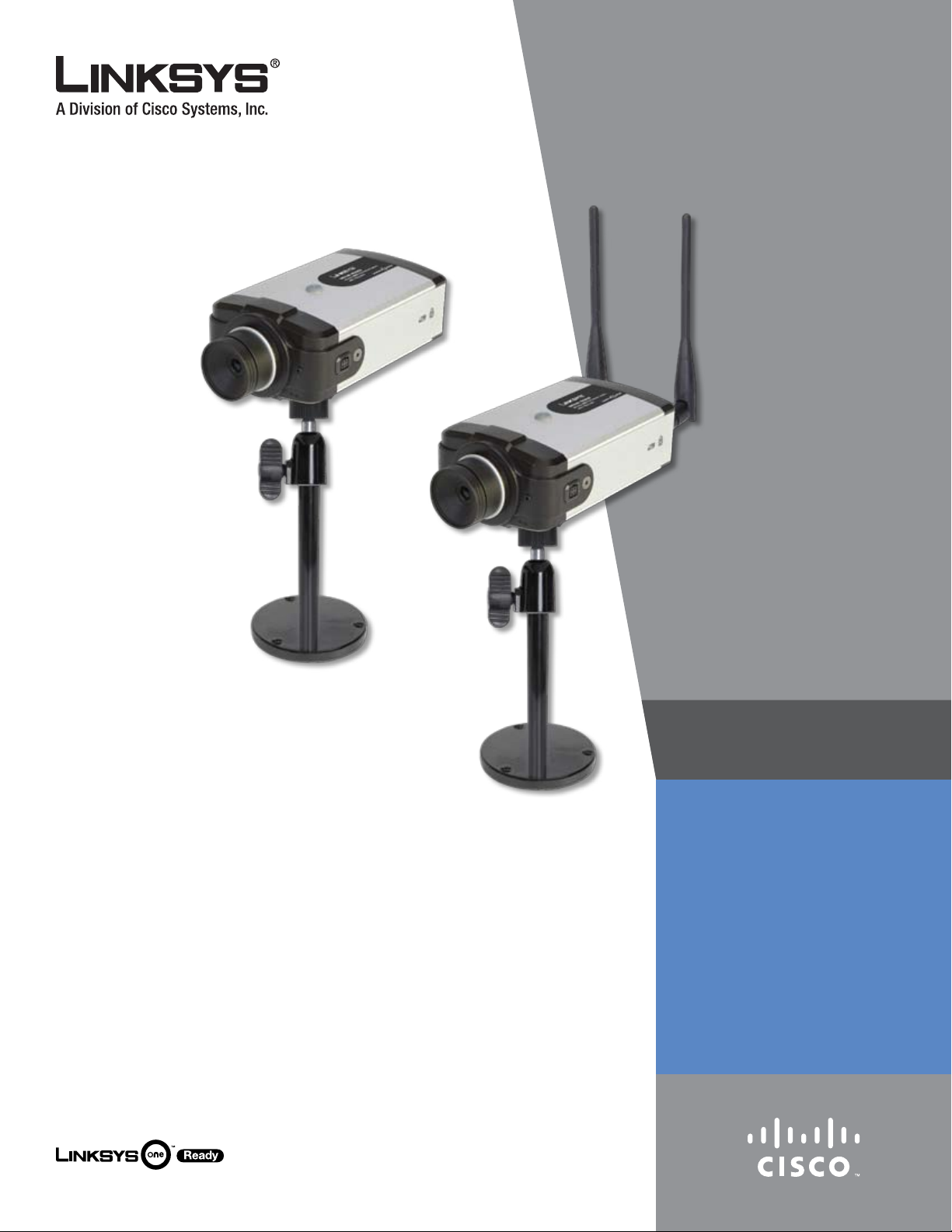
Thank you for choosing the Linksys Business Internet Video
Camera with Audio. This User Guide covers two models:
PVC2300 • Business Internet Video Camera with Audio
and PoE (Power over Ethernet)
WVC2300 • Wireless-G Business Internet Video Camera
with Audio
NOTE: For the purpose of this User Guide,
whenever a feature applies to both models, the
word Camera(s) will be referenced. If a specific
model number is mentioned, then the feature
is specific to that model.
The new Linksys Surveillance solutions are high quality
solutions which can be optimized for many different
applications. The box-type form factor allows these
cameras to be used as-is or put inside an outdoor enclosure
for interior or exterior applications. The cameras use
removable CS-mount lenses and can be customized with
Zoom, Wide-Angled, Vari-focal, Auto-Iris, or other type of
lenses as required for the specific application.
The PVC2300 provides Power over Ethernet (PoE)
functionality that facilitates installation of the PVC2300 in
places without reach of a power outlet.
The Cameras can be mounted on any PT base that
supports Pelco_D protocol and can be remotely rotated
and controlled through an RS-485 interface. The Camera
supports 2 input and 2 output connectors which can be
used for connecting to an alarm panel, siren, PIR, smoke
detectors, light switch (on/off), door opener, etc.
The Cameras incorporate a high quality progressive scan
CCD sensor, delivering good quality undistorted video.
The sensor used in the Cameras has Low light sensitivity
capability. This means that video can be viewed when
very low light (near darkness) is present. Additionally, the
Cameras incorporate an IR Cut Filter switcher which, when
used with a separate IR lamp, allows for viewing of video
in total darkness.
With extensive feature support like IP Multicast, RTSP, RTP,
and 3GPP, video can be viewed from multiple endpoints
and client applications like 3G phones, and Quicktime
clients on PCs or Wi-Fi phones.
Support for multiple network protocols like 802.1p priority,
802.1q VLANs, and Dynamic DNS, make the solution ideal
for multiple IP surveillance applications. The Cameras can
also be managed securely using HTTPS.
Linksys Business Series Surveillance Cameras are also
Linksys One Ready. That means they include the necessary
firmware to be integrated into a Linksys One data or data/
voice network.
Minimum Requirements
Minimum System Requirements (for 1 camera):
CPU Pentium 4 class, 2 GHz
Memory 512 MB
Operating System Microsoft Windows 2000, XP or Vista
Hard Drive 500 MB of available space
Graphics Card AGP with a minimum 128 MB
Browser
Minimum System Requirements
(for up to 8 cameras):
CPU Pentium 4 class, 3 GHz dual-core
Memory
Operating System Microsoft Windows 2000, XP or Vista
Hard Drive 4 GB of available space
Internet Explorer 6.0 (or above), Mozilla
Firefox, and Netscape 7.0 (or above)
1 GB
The Cameras support dual CODECs - MPEG-4 and MJPEG.
Both CODECs can be used simultaneously. MPEG-4 gives
efficient bandwidth consumption with good quality
compression and is optimal for real-time viewing of video.
MJPEG gives optimal video quality in lossy environments
making it ideal for video storage to a NAS device.
The Camera’s audio capabilities include 2-way audio, an
embedded microphone, external speaker and microphone
ports, and voice compression.
Business Internet Video Camera with Audio
Graphics Card
Browser
NOTE: For 9 cameras or more, reduce the
resolution and frame rate settings and the same
minimum requirements apply as listed above.
NVidia high performance or equivalent
with a minimum 256 MB
Internet Explorer 6.0 (or above), Mozilla
Firefox, and Netscape7.0 (or above)
1

Chapter 1
Introduction
Camera Accessories
Lens Specifications
The following lens can be used with the PVC2300 and
WVC2300 IP cameras:
Lens
CIVS-IPC-VT38Tamron 3-8 mm
Varifocal Lens
CIVS-IPC-VT31 Tamron 3-11 mm
Varifocal Lens
C IV S - I P C - V T 55
Tamron 5-50 mm
Varifocal Lens
Cisco Video Surveillance 2500 Series IP
Camera documentation at www.cisco.
com
Cisco Video Surveillance 2500 Series IP
Camera documentation at www.cisco.
com
Cisco Video Surveillance 2500 Series IP
Camera documentation at www.cisco.
com
Enclosure Specifications
The following enclosure can be used with the PVC2300
and WVC2300 IP cameras
Enclosure
CAMEE1-Camera Exterior
Enclosure with Heater and
Blower
Camera Accessory datasheet at
www.cisco.com
C I V S - IP C -V F 38
Fujinon 3-8 mm
Varifocal Lens
C I V S - IP C -V F 31
Fujinon 3-11 mm
Varifocal Lens
C I V S - IP C -V F 55
Fujinon 5-50 mm
Varifocal Lens
CAMLMI Tamron
1/3” 3~8mm
Varifocal 2.7X
Zoom Lens
C A M L W A
Computar 1/3”
2.3mm Wide Angle
Lens
Cisco Video Surveillance 2500 Series IP
Camera documentation at www.cisco.
com
Cisco Video Surveillance 2500 Series IP
Camera documentation at www.cisco.
com
Cisco Video Surveillance 2500 Series IP
Camera documentation at www.cisco.
com
Camera Accessory datasheet at www.
cisco.com
Camera Accessory datasheet at www.
cisco.com
Business Internet Video Camera with Audio
2

Chapter 2
Wireless Security Checklist
Chapter 2: Wireless Security Checklist
Wireless networks are convenient and easy to install, so
businesses with high-speed Internet access are adopting
them at a rapid pace. Because wireless networking operates
by sending information over radio waves, it can be more
vulnerable to intruders than a traditional wired network.
Like signals from your cellular or cordless phones, signals
from your wireless network can also be intercepted. Since
you cannot physically prevent someone from connecting
to your wireless network, you need to take some additional
steps to keep your network secure.
1. Change the default
wireless network name or
SSID
Wireless devices have a default wireless network name
or Service Set Identifier (SSID) set by the factory. This
is the name of your wireless network, and can be up
to 32 characters in length. Linksys wireless products
use linksys as the default wireless network name. You
should change the wireless network name to something
unique to distinguish your wireless network from other
wireless networks that may exist around you, but do not
use personal information (such as your Social Security
number) because this information may be available for
anyone to see when browsing for wireless networks.
2. Change the default
password
so that only those computers can access your wireless
network.
4. Enable encryption
Encryption protects data transmitted over a wireless
network. Wi-Fi Protected Access (WPA/WPA2) and Wired
Equivalency Privacy (WEP) offer different levels of security
for wireless communication. Currently, devices that are
Wi-Fi certified are required to support WPA2, but are not
required to support WEP.
A network encrypted with WPA/WPA2 is more secure
than a network encrypted with WEP, because WPA/WPA2
uses dynamic key encryption. To protect the information
as it passes over the airwaves, you should enable the
highest level of encryption supported by your network
equipment.
WEP is an older encryption standard and may be the
only option available on some older devices that do not
support WPA.
General Network Security Guidelines
Wireless network security is useless if the underlying
network is not secure.
Password protect all computers on the network and •
individually password protect sensitive files.
Change passwords on a regular basis. •
Disable file sharing (peer-to-peer). Some applications •
may open file sharing without your consent and/or
knowledge.
For wireless products such as access points and routers,
you will be asked for a password when you want to change
their settings. These devices have a default password set
by the factory. The Linksys default password is admin.
Hackers know these defaults and may try to use them
to access your wireless device and change your network
settings. To thwart any unauthorized changes, customize
the device’s password so it will be hard to guess.
3. Enable MAC address
filtering
Linksys routers give you the ability to enable Media Access
Control (MAC) address filtering. The MAC address is a
unique series of numbers and letters assigned to every
networking device. With MAC address filtering enabled,
wireless network access is provided solely for wireless
devices with specific MAC addresses. For example, you can
specify the MAC address of each computer in your home
Business Internet Video Camera with Audio
Additional Security Tips
Keep wireless routers, access points, or gateways away •
from exterior walls and windows.
Turn wireless routers, access points, or gateways •
off when they are not being used (at night, during
vacations).
Use strong passphrases that are at least eight characters •
in length. Combine letters and numbers to avoid using
standard words that can be found in the dictionary.
3
Chapter 3
Product Overview
Chapter 3: Product Overview
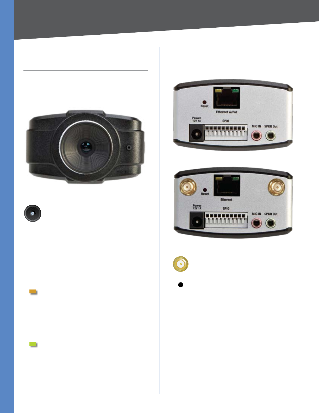
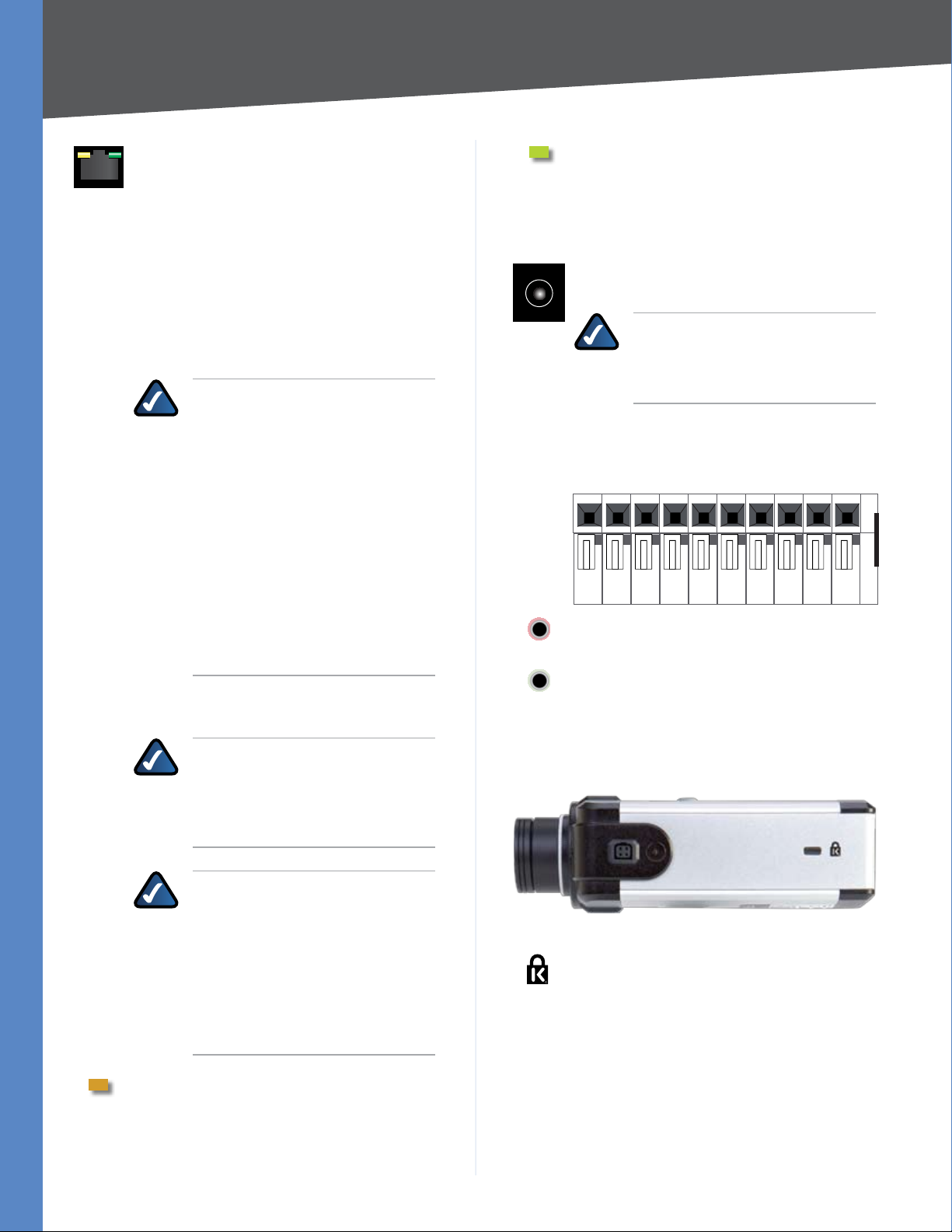
Front Panel
The LEDs and Camera lens are located on the front panel
of the Camera.
Front Panel
Back Panel
The ports and reset button are located on the back panel
of the Camera.
Back Panel - PVC2300
Lens The Camera includes a removable
CS-mount lens. For specifications on the
included lens, refer to the Specifications section
of this User Guide. For a list of recommended
lenses to use with this Camera, please refer to
the Quick Installation Guide.
Built-in microphone There is a built-in
microphone mounted on the front of the
Camera. The Camera also has a connection for
an external microphone on the rear. Connecting
an external microphone will disable the built-in
microphone.
Ready LED (Amber) The Ready LED has the
following states:
Off • Camera is powered off.
On • Camera is powered on.
Flashing • The Ready LED will flash during
start up. This will take 15 to 20 seconds.
Network LED (Green) The Network LED has
the following states:
Off • Network connection not detected.
On • Network connection detected.
Flashing • Sending/receiving data.
Back Panel - WVC2300
Antenna Connectors Antenna connectors
are only found on the WVC2300 Camera. The
connectors are used to attach the antennas to
the device for wireless connectivity.
Reset The reset button can be accessed with
a straightened paper clip or similar object. The
reset button has two functions:
Restore Factory Defaults • To restore the
factory default settings, press the Reset
button for more than 10 seconds. When you
let go of the button, the LEDs on the front
of the Camera will flash and then return to a
normal state when the Camera is ready.
Set Static IP Address • By default the
camera is set to receive an IP address from
a DHCP server. If you do not have a DHCP
server on your network, you can set a static
IP address by pressing the Reset button
on the camera for less than 10 seconds. A
default IP address of 192.168.1.99 will be
assigned to the camera.
Business Internet Video Camera with Audio
4
Chapter 3
10 9 8 7 6 5 4 3 2 1
Product Overview
Ethernet The Ethernet port supports network
speeds of either 10 Mbps or 100 Mbps, and can
operate in half and full-duplex mode.
Auto-sensing technology enables the port to
automatically detect the speed of the device
connected to it (10 Mbps or 100 Mbps), and
adjust its speed and duplex accordingly.
The Ethernet port supports automatic MDI/
MDI-X operation, so you can use straightthrough or crossover cables to connect to PCs,
servers, or switches.
NOTE FOR PVC2300 USERS: The
PVC2300 Camera’s Ethernet port also
supports the IEEE 802.3af Power-overEthernet (PoE) standard that enables
DC power to be supplied to the
Camera using wires in the connecting
twisted-pair cable. Any 802.3afcompliant device attached to the
port can directly supply power to the
Camera over the twisted-pair cable
without requiring its own separate
power source. This capability gives
network administrators centralized
power control, which translates into
greater network availability.
To connect a device to the port, you will need
to use Category 5 (or better) network cable.
NOTE FOR WVC2300 USERS:
Attaching an Ethernet cable will
disable the wireless interface on the
WVC2300 Camera. Only one interface
can be active at any time.
PVC2300 PoE LED This LED only functions on
the PVC2300 Camera. The LED has the following
states:
On PoE connection is detected.
Off PoE connection is not detected.
Power The Power port is where you will
connect the power adapter.
NOTE FOR PVC2300 USERS: The
Power port is automatically turned of
if a PoE connection is detected on the
Ethernet port.
GPIO This port is utilized for I/O connections.
Detailed specifications can be found in the
Specifications section of this User Guide.
Mic In This jack is used to connect an external
microphone to the camera.
Spkr Out This jack is used to connect powered
speakers to the Camera.
Side Panel
The security slot is located on a side panel of the Camera.
NOTE FOR WVC2300 USERS: On
the WVC2300 Camera, the Ethernet
cable should only be connected or
disconnected when the Camera is
powered OFF. Attaching or detaching
the Ethernet cable while the Camera
is powered on does NOT switch
the interface between wired and
wireless.
Activity LED The Activity LED flashes when
activity is detected on the Ethernet port.
Business Internet Video Camera with Audio
Side Panel
SECURITY SLOT The security slot can be
utilized to attach a lock to the Camera.
5
Chapter 4
Installation
Chapter 4: Installation
Overview
This chapter will explain how to install the Camera into a
wired or wireless network. The following diagrams show
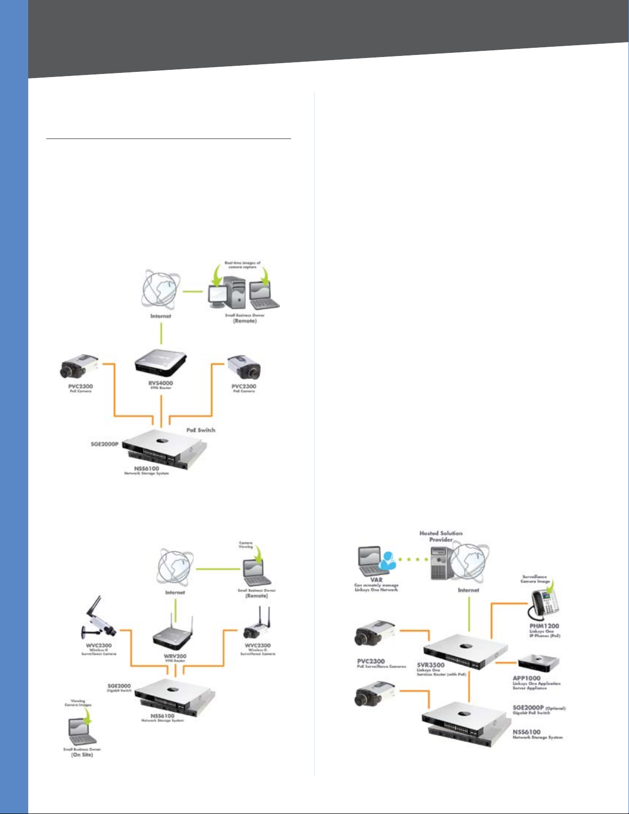
some typical network configurations.
Linksys Wired Network
Linksys One Ready
When the Camera is connected to a Linksys One network,
you can access the images using the Linksys One Video
Surveillance Application (VSA) from any PHM1200 IP
phone or web browser. The Linksys One VSA is a zero
configuration plug-and-play application. The Camera
sends live video feeds at a rate of 2 fps (frames per second)
to your phone or web browser, with the option to receive
alerts for motion detection and other events. You can easily
configure the system to store video captures, send event
notifications via e-mail, and operate with devices such as
alarm systems, solenoid locks, and lighting controls.
The Linksys One VSA works in conjunction with the
following Linksys and Linksys One devices:
Linksys One Application Server Appliance, model •
APP1000 (Required)
Linksys One Ready Business Internet Video Camera •
with Audio, model PVC2300 or WVC2300 (Required)
Linksys One Services Router, model SVR200 required if •
a WVC2300 camera is installed (Required)
Linksys One IP Phone, PHM1200 (Optional) •
Example Linksys Wired Network
Linksys Wireless Network
Linksys One Ready Switches, any model (Optional) •
Linksys One Ready Network Attached Storage Device, •
any model, or FTP server for the storage of video files
(Optional)
End-user documentation, including the Linksys One Video
Surveillance Application User Guide (v2.1 or above) is
available on the web at www.linksysone.com
Linksys One Wired Network
Example Linksys Wireless Network
Business Internet Video Camera with Audio
Example Linksys One Wired Network
6
Chapter 4
LINK/ACT
PoE
LINK/ACT
PoE
LINK/ACT
Gigabit
LINK/ACT
Gigabit
Installation
Linksys One Wireless Network
Example Linksys One Wireless Network
Hardware Installation
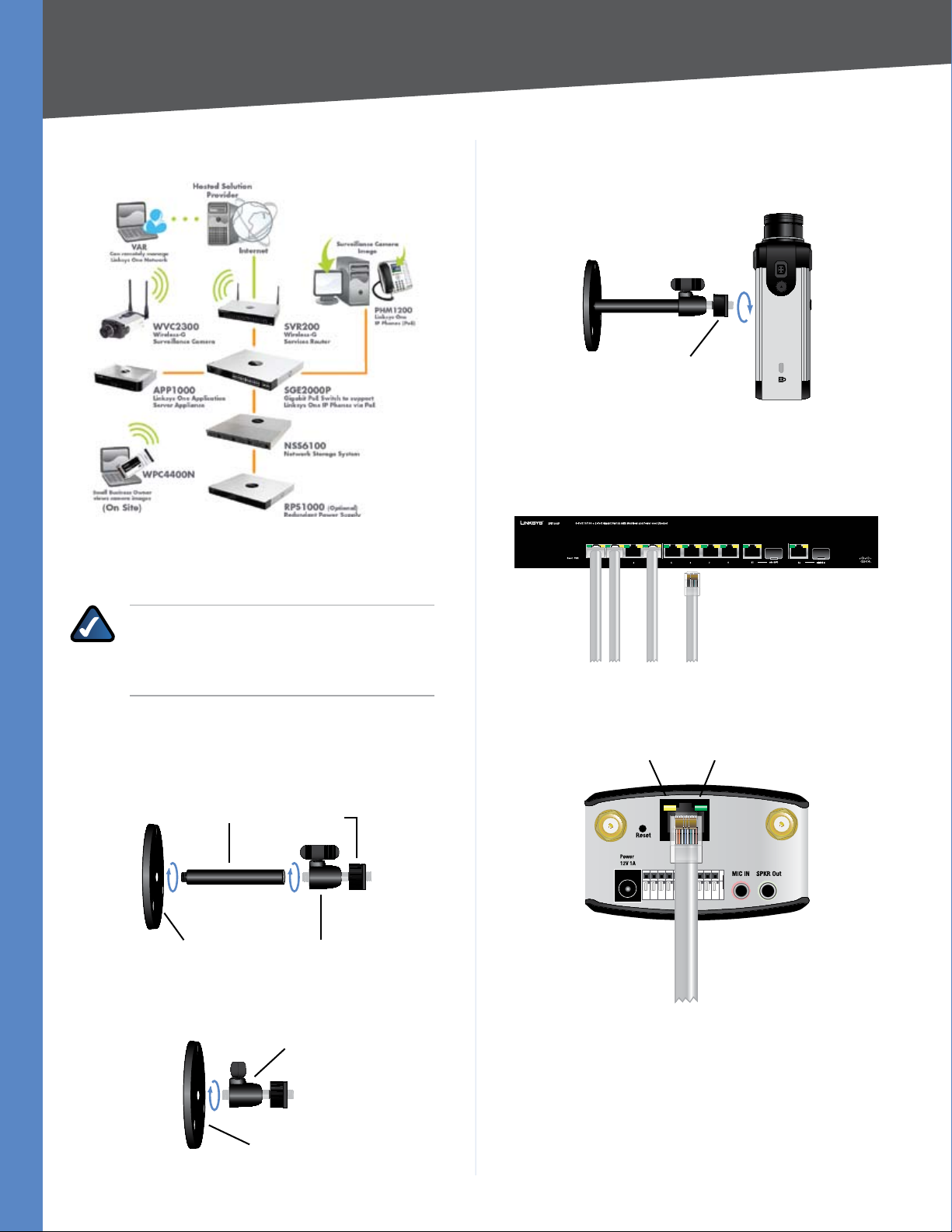
Connect the camera stand to the bottom of the 2.
camera. Adjust the camera to the appropriate viewing
position.
Locknut
Once the camera is positioned properly, secure the
camera in place by tightening the locknut.
Connect the included Ethernet network cable to your 3.
network router or switch.
NOTE: Before attaching the camera extension or
swivel head, the stand base can be mounted in
a permanent location by using three screws to
secure the stand base to the desired location.
The Camera stand can be connected two different 1.
ways:
Attach the stand base to the camera extension and •
attach the camera extension to the swivel head.
Camera Extension
Stand Base
Locknut
Swivel Head
You can connect the swivel head directly to the stand •
base if the extension isn’t necessary.
Swivel Head
Connect the other end of the cable to the Camera’s 4.
Ethernet port.
LEDs
Link PoE
If your network switch provides Power over Ethernet
to the Camera, verify the Camera’s LEDs are lit and skip
steps 5-7.
Business Internet Video Camera with Audio
Stand Base
Connect the included power adapter to the Camera’s 5.
Power port and plug the other end into a standard
electrical outlet.
7
Chapter 4
Verify that the Camera’s LEDs are lit.
Installation
Configuration
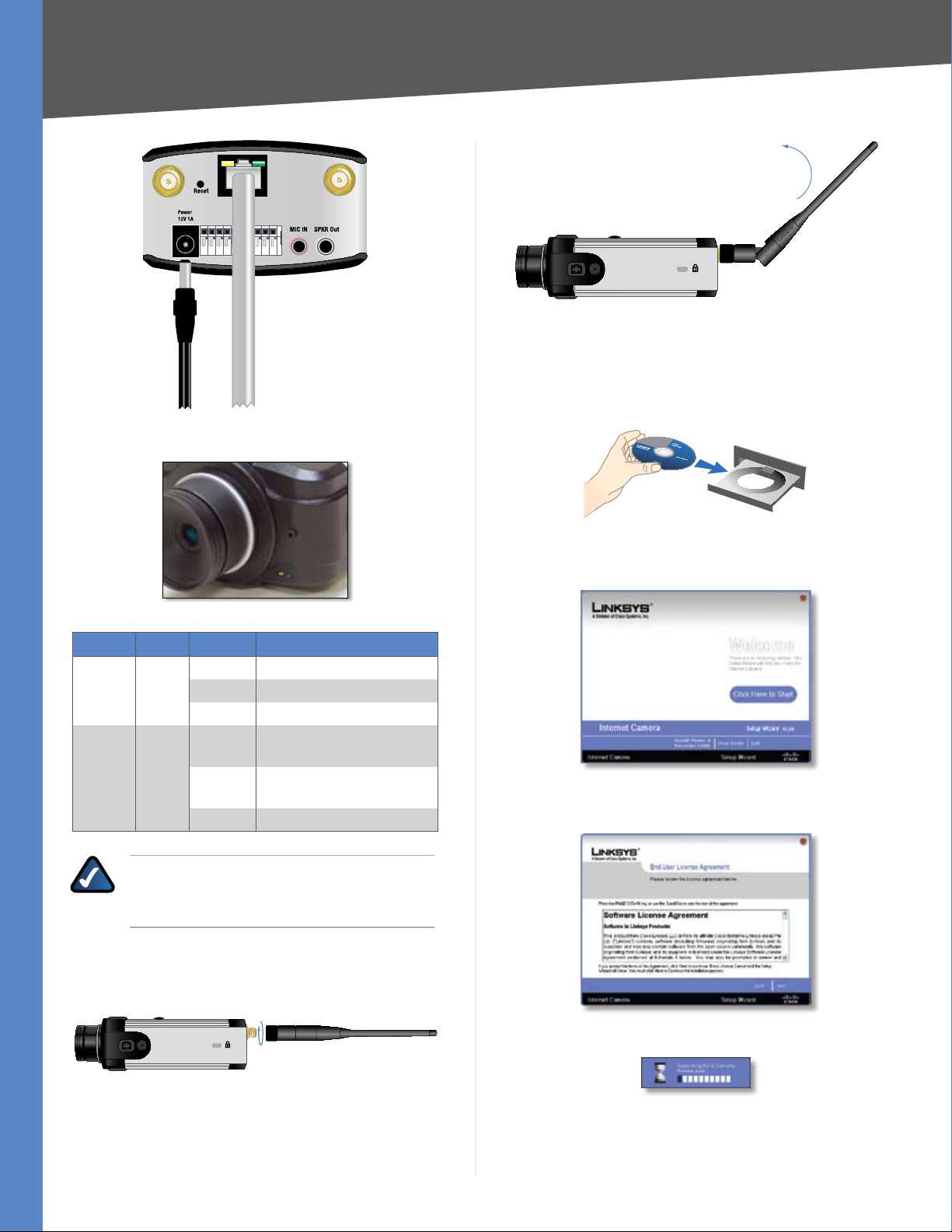
Insert the Setup CD into your CD-ROM drive. If the CD 1.
doesn’t run automatically, go to My Computer and
click on your CD-ROM drive.
LED Table
LED Color Activity Action
Off Camera is powered off
Ready Amber
Network Green
NOTE: Hardware Installation steps 6 and 7 are
only necessary if you are using the WVC2300
Wireless-G Business Internet Video Camera.
Connect the antennas to the antenna connectors on 6.
the Camera.
On Camera is powered on
Blink Camera is booting
Off
On
Blink Sending/receiving data
Network connection not
detected
Network connection
detected
The Setup screen will appear. Click the 2. Click Here to
Start button.
The license agreement screen will appear, click 3. Next if
you agree and wish to proceed.
Place the antennas in an upright position.7.
Business Internet Video Camera with Audio
The Wizard will now search for your camera.4.
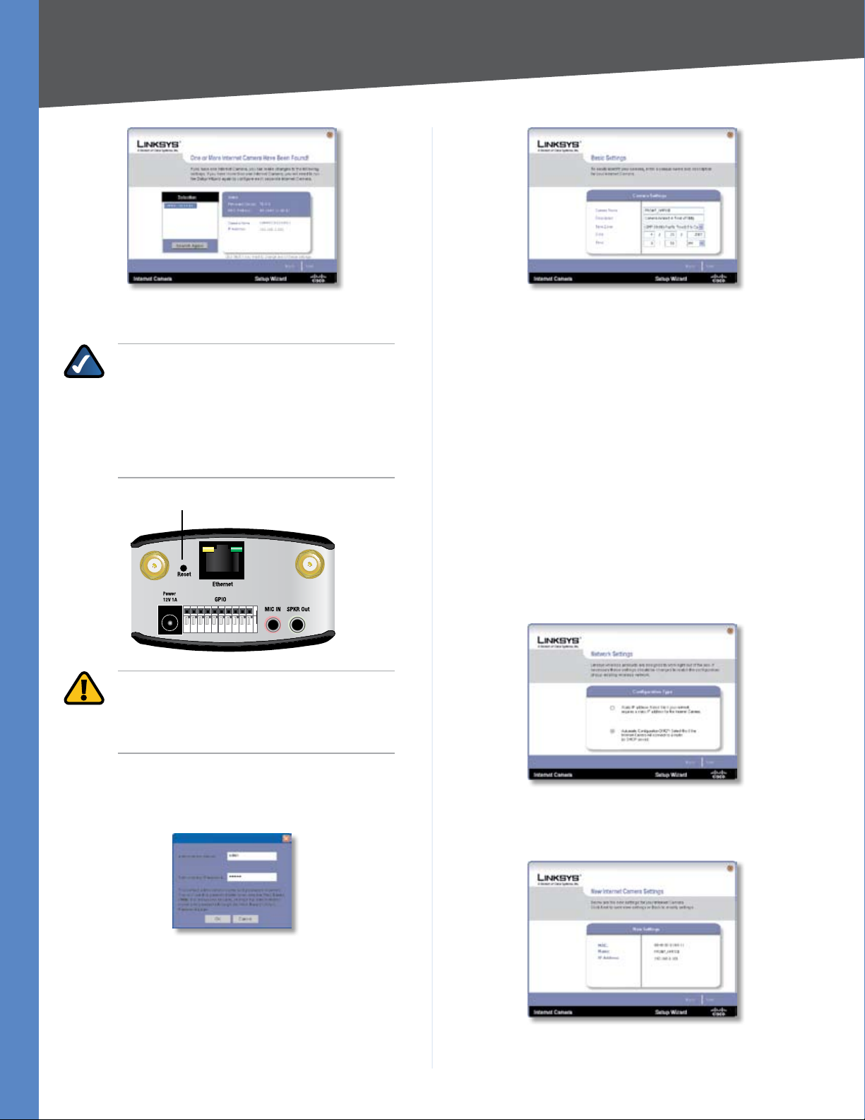
Once found highlight the camera and click Next.
8
Chapter 4
Installation
If the Camera you want is not displayed in the Selection
box, click Search Again.
NOTE: The Camera defaults to DHCP mode. If
your network doesn’t have a DHCP server or if
you are having issues obtaining an IP address,
you can assign a static IP address to the Camera
by pressing the reset button for less than 10
seconds. A static IP address of 192.168.1.99
will be assigned to the Camera.
Reset Button
WARNING: Pressing the reset button for more
than 10 seconds will restore all of the factory
default settings, including setting the Camera
to DHCP mode.
Camera Name – Enter a unique name for the
Camera, up to 15 characters in length. Unique
names are helpful when you are using multiple
Cameras on the same network.
Description – Enter a description, up to 32
characters in length, with additional information,
such as the location of the Camera.
Time Zone – Select the time zone that corresponds
with the Camera’s location.
Date – Enter the current date in the provided fields.
Time – Enter the current time in the provided fields.
When you have finished making changes, click
Next.
If you want to assign the IP address, then select 7. Static
IP address, otherwise leave the default setting,
Automatic Configuration DHCP.
The default user name and password is admin. Type 5.
admin in lowercase letters, in the Administrator Name
and Administrator Password fields, then click OK.
For security purposes, it is recommended that you
change the default name and password using the
Camera’s web-based utility at a later time.
On the 6. Basic Settings screen, change the following
settings:
Business Internet Video Camera with Audio
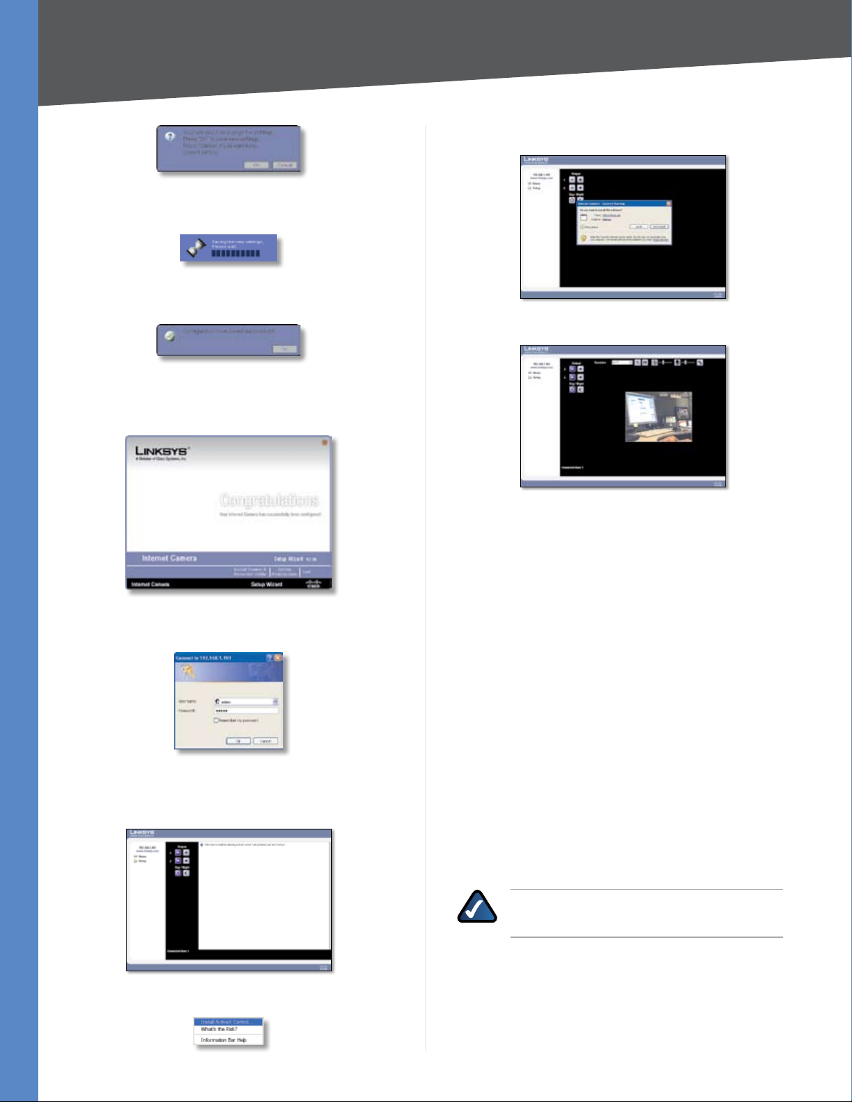
The New Internet Camera Settings screen will appear 8.
and display the Camera’s settings. Click Next to
continue or click Back to make changes.
A confirmation window will appear, click 9. OK to confirm
the settings.
9
Chapter 4
A timer will appear as the settings are saved to the
Camera.
A window will appear indicating that the settings have 10.
been saved successfully. Click OK to continue.
The Wizard will now return to the 11. Welcome screen. Click
Exit to automatically launch your default web browser
and proceed to the Home page login screen.
Installation
Click the 14. Install button.
You should be able to view video on the home page.
The login prompt will appear, enter admin in both the 12.
User name and Password fields.
Internet Explorer will prompt you to install ActiveX. 13.
In order to view video you must accept the ActiveX
download.
Setting Up the Wireless Connection on the WVC2300 Camera
To configure the Camera for wireless connectivity, you
must still be connected to the home page.
Click on 1. Setup to open the Setup > Basic Setup screen.
Enter the appropriate Wireless Settings:2.
SSID The SSID is the network name shared among all
devices in a wireless network. Enter the network’s SSID or
network name here. The SSID is case sensitive.
Network Type Select the appropriate network mode:
Infrastructure • Use this option if you are connecting
the Camera to an access point or router.
Ad-hoc • Use this option if you are connecting the
Camera directly to a PC or notebook.
Channel No If the Camera is set to ad-hoc mode, select
its channel setting from the drop-down menu.
NOTE: When using Infrastructure mode, the
channel setting is configured automatically.
Click Install ActiveX Control.
Business Internet Video Camera with Audio
Security Click the Edit Security Settings button to
display the Wireless Security screen.
10
Chapter 4
Installation
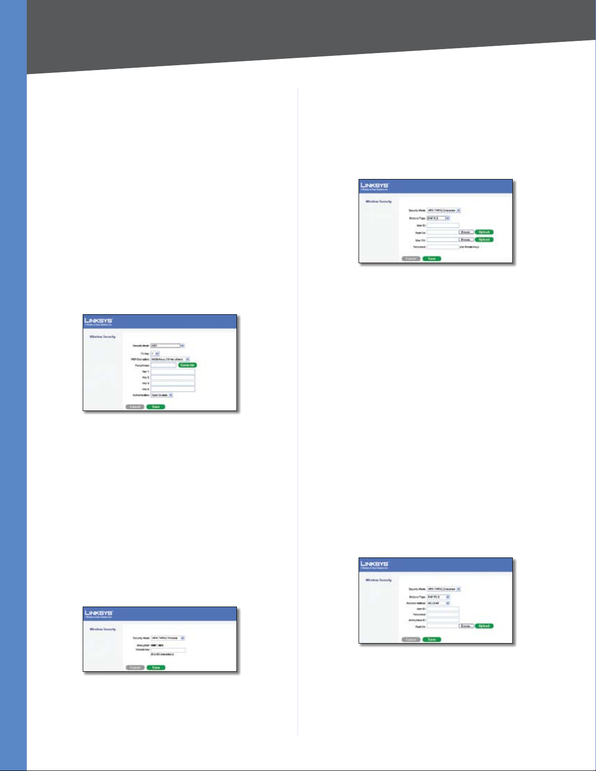
Wireless Security
Security Mode Select the appropriate option based on
your wireless network configuration:
Disabled • This option implements no security on
your wireless network. Data is not encrypted before
transmission.
WEP • WEP is a basic encryption method, which is not
as secure as later methods such as WPA-Personal or
WPA2 Personal. However, it is supported by all clients.
WPA /WPA2 Personal • This method offers two
encryption methods, TKIP and AES, with dynamic
encryption keys.
WPA /WPA2 Enterprise • This option requires that
your LAN has a RADIUS server for authentication.
WEP
WPA /WPA2 Enterprise
The screen options vary depending upon the protocol
type selected.
Protocol Type Select EAP-TLS or EAP-TTLS.
EAP-TLS
Wireless Security > Security Mode > WPA /WPA2 Enterprise (EAP-TLS)
User ID • The user ID used to login to your RADIUS
server.
Root CA • A root certificate is an unsigned public key
certificate, or a self-signed certificate, which implies
that you trust your browser’s publisher to include
correct root certificates, and in turn the certificate
authorities it trusts, and anyone to whom the CA may
have issued a certificate-issuing-certificate, to faithfully
authenticate the users of all their certificates.
Wireless Security > Security Mode > WEP
TX Key Select the number of the key used on the wireless
network.
WEP Encryption Select the appropriate option for key
length based on your network settings.
Passphrase Type in the passphrase used to generate WEP
keys on your network and click the Generate button.
Key 1-4 Key values can be entered in manually or
generated from a passphrase.
Authentication Select the appropriate authentication
type used on the wireless network.
WPA /WPA2 Personal
Wireless Security > Security Mode > WPA /WPA2 Personal
Encryption This cannot be modified.
Shared Key Enter the shared key used for accessing the
wireless network.
User CA • A user certificate is a signed private key
certificate, which implies that you trust your browser’s
publisher to include correct user certificates, and in
turn the certificate authorities it trusts, and only user
to whom the CA may have issued a certificate-issuingcertificate, to faithfully authenticate the users of all
their certificates.
Password • This is for this Camera’s client login to the
RADIUS server, and must match the key stored on the
RADIUS server.
EAP-TTLS
Wireless Security > Security Mode > WPA /WPA2 Enterprise (EAP-TTLS)
Process Method • Choose an authentication method
as required to handle the processing and transmitting
of CA to your RADIUS server.
User ID • The user ID used for login to your RADIUS
server.
Business Internet Video Camera with Audio
11
Chapter 4
Installation
Password • This is for this Camera’s client login to the
RADIUS server.
Anonymous ID • The unsigned public ID used for login
to your RADIUS server.
Root CA • A root certificate is an unsigned public key
certificate, or a self-signed certificate, which implies
that you trust your browser’s publisher to include
correct root certificates, and in turn the certificate
authorities it trusts, and anyone to whom the CA may
have issued a certificate-issuing-certificate, to faithfully
authenticate the users of all their certificates.
Click 3. Save to save the wireless security settings and
close out the window manually.
On the 4. Setup > Basic Setup screen, click the Save button
to save the wireless settings.
Disconnect the power to the Camera.5.
Disconnect the Ethernet Cable from the Camera.6.
NOTE: The wireless connection will not work
if an Ethernet cable is attached to the Camera
when it is powered on.
Reconnect the power to the Camera.7.
Business Internet Video Camera with Audio
Click on 8. Home in the web-based utility to verify the
video is streaming from your wireless connection. You
should be able to view video on the home page.
12
Chapter 5
Installing and Using the Viewer and Recorder Software
Chapter 5: Installing and Using the Viewer and Recorder Software
Overview
This chapter will instruct you on how to install and use the
Internet Camera Viewer & Recorder Utility on your PC. The
Utility allows you to easily view and record video.
If another Internet Camera Viewer & Recorder Utility has
already been installed on your PC, you should uninstall it
before installing this software.
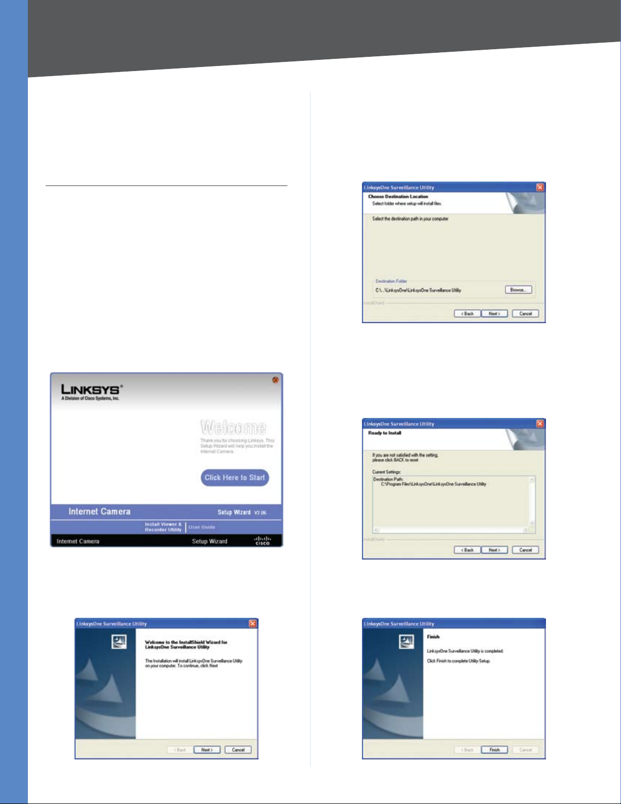
Installing the Software
On the 1. Welcome screen of the Setup Wizard, click
Install Viewer & Recorder Utility.
Welcome Screen
The 3. Choose Destination Location screen will appear. To
install the Viewer & Recorder Utility files in the default
folder, click the Next button. To select a different folder,
click the Browse button and follow the on-screen
directions.
Choose Destination Location
The 4. Ready to Install screen will appear. The selected
destination path will be displayed. If you wish to change
the path, click the Back button. If you are satisfied with
the location, click the Next button to continue.
Setup Wizard Welcome Screen
The 2. Welcome screen will appear. Click the Next button
to proceed.
Business Internet Video Camera with Audio
Ready to Install
Click 5. Finish to complete the installation.
13
Chapter 5
Installing and Using the Viewer and Recorder Software
Using the Monitor Application
After the software has been installed, you can launch the
application from shortcuts on the desktop and in the Start
menu.
Desktop Shortcuts
Once you’ve launched the Monitor application, you will
see the Monitor’s main screen. From this screen, you can
configure and control Cameras.
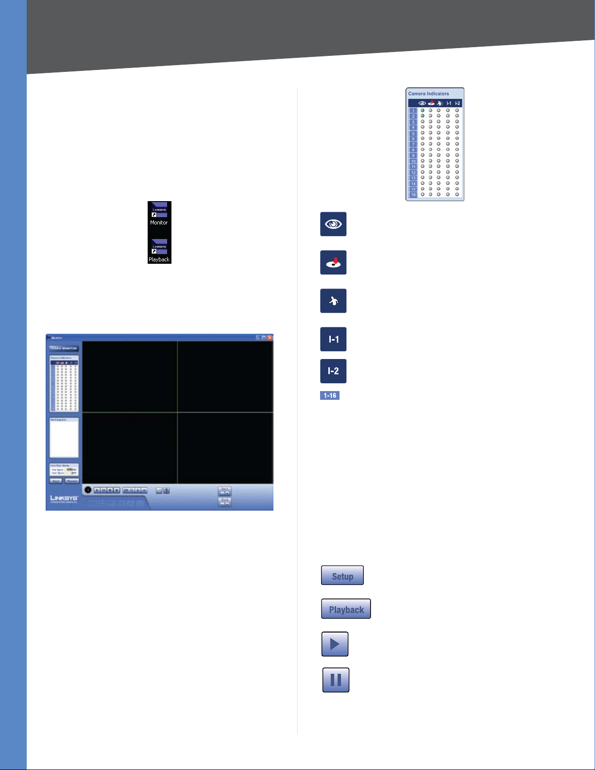
Viewing When a Camera has a green
light under this icon, it indicates the
video is being viewed.
Recording When a Camera has a red
light under this icon, it indicates that
video is being recorded.
Motion When a Camera has a light
under this icon, it indicates that motion
has been detected.
Input 1 This indicates that input 1 has
been triggered.
Monitor Main Screen
Video Monitor
The following list details the function of the icons found
on the Video Monitor screen.
Camera Indicators
The Video Monitor includes a camera indicator window.
The icons indicate the activities associated that are active
for the Cameras.
Input 2 This indicates that input 2 has
been triggered.
Camera Number This indicates which
Camera number the indicators apply to.
Alert Log List
Alert Log List Displays any alert messages.
Hard Disk Quota
Free Space Displays the amount of free space available at
the recording path defined in the preferences. By default
this is your local drive.
Used Space Displays the amount of space used by video
clips captured using the utility.
Setup Clicking this button opens the
Camera Setup window.
Playback Clicking this button opens
the Video Playback window.
Play Use this button to re-start viewing,
after using the Stop or Pause button.
Business Internet Video Camera with Audio
Pause Clicking this pauses the video
stream.
14
 Loading...