

Page 1
Fast Start
Guide
Instant Broadband™ Series
ADSLGateway
Modem / Router / 4-Port Switch / Wireless-Ready
Use this guide to install:
BEFDSR41W
Page 2

ADSL Gateway
with Modem / Router / 4-Port Switch / Wireless-Ready
1
Table of Contents
English 1
Français 24
Deutsch 46
Italiano 68
Portuguese 90
Español 112
EC DECLARATION OF CONFORMITY (EUROPE)
Linksys Group declares that the Instant Wireless™ Series products included in the Instant
Wireless™ Series conform to the specifications listed below, following the provisions of the
EMC Directive 89/336/EEC and Low Voltage Directive 73/23/EEC:
• ETS 300-826, 301 489-1 General EMC requirements for Radio equipment.
• EN 609 50 Safety
• ETS 300-328-2 Technical requirements for Radio equipment.
Note: This equipment is intended to be used in all EU and EFTA countries. Outdoor use may
be restricted to certain frequencies and/or may require a license for operation. For more
details, contact Linksys Corporate Compliance.
Note: Combinations of power levels and antennas resulting in a radiated power level of
above 100 mW are considered as not compliant with the above mentioned directive and are
not allowed for use within the European community and countries that have adopted the
European R&TTE directive 1999/5/EC and/or the CEPT recommendation Rec 70.03. For
more details on legal combinations of power levels and antennas, contact Linksys Corporate
Compliance.
• Linksys Group™ vakuuttaa täten että Instant Wireless IEEE 802.11 PC Card tyyppinen
laite on direktiivin 1999/5/EY, direktiivin 89/336/EEC ja direktiivin 73/23/EEC oleellisten
vaatimusten ja sitä koskevien näiden direktiivien muiden ehtojen mukainen.
• Linksys Group™ déclare que la carte PC Instant Wireless IEEE 802.11 est conforme aux
conditions essentielles et aux dispositions relatives à la directive 1999/5/EC, la directive
89/336/EEC, et à la directive 73/23/EEC.
• Belgique B L’utilisation en extérieur est autorisé sur le canal 11 (2462 MHz), 12 (2467
MHz), et 13 (2472 MHz).
Dans le cas d’une utilisation privée, à l’extérieur d’un bâtiment, au-dessus d’un espace
public, aucun enregistrement n’est nécessaire pour une distance de moins de 300m. Pour
une distance supérieure à 300m un enregistrement auprès de l’IBPT est requise. Pour
une utilisation publique à l’extérieur de bâtiments, une licence de l’IBPT est requise. Pour les
enregistrements et licences, veuillez contacter l’IBPT.
• France F: Bande de fréquence restreinte: seuls les canaux 10, 11, 12, 13 (2457, 2462,
2467, et 2472 MHz respectivement) doivent être utilisés en France. Toute utilisation,
qu'elle soit intérieure ou extérieure, est soumise à autorisation. Vous pouvez contacter
l'Autorité de Régulation des Télécommuniations (http://www.art-telecom.fr) pour la
procédure à suivre.
• France F: Restricted frequency band: only channels 10, 11, 12, 13 (2457, 2462, 2467,
and 2472 MHz respectively) may be used in France. License required for every indoor
and outdoor installations. Please contact ART for procedure to follow.
• Deutschland D: Anmeldung im Outdoor-Bereich notwending, aber nicht genehmigungspflichtig. Bitte mit Händler die Vorgehensweise abstimmen.
• Germany D: License required for outdoor installations. Check with reseller for procedure
to follow.
• Italia I: E' necessaria la concessione ministeriale anche per l'uso interno. Verificare con i
rivenditori la procedura da seguire. L'uso per installazione in esterni non e' permessa.
• Italy I: License required for indoor use. Use with outdoor installations not allowed.
• the Netherlands NL License required for outdoor installations. Check with reseller for
procedure to follow.
• Nederlands NL Licentie verplicht voor gebruik met buitenantennes. Neem contact op
met verkoper voor juiste procedure.
Page 3

COPYRIGHT & TRADEMARKS
Copyright © 2002 Linksys, All Rights Reserved. Microsoft, Windows, and the Windows logo
are registered trademarks of Microsoft Corporation. All other trademarks and brand names
are the property of their respective proprietors.
FCC PART 15 CLASS B STATEMENT
In compliance with the Federal Communications Commission (FCC), the following FCC
Part 15 Regulations are provided regarding the installation and operation of the Linksys
BEFDSR41W ADSL Gateway.
This equipment has been tested and found to comply with the limits for a Class B digital
device, pursuant to Part 15 of the FCC Rules. These limits are designed to provide reasonable protection against harmful interference in a residential installation.
This equipment generates, uses and can radiate radio frequency energy and, if not installed
and used in accordance with the instructions, may cause harmful interference to radio communications. However, there is no guarantee that interference will not occur in a particular
installation. If this equipment does cause harmful interference to radio or television reception, which can be determined by turning the equipment off and on, the user is encouraged
to try to correct the interference by one or more of the following measures:
• Reorient or relocate the receiving antenna.
• Increase the separation between the equipment and the receiver.
• Connect the equipment to an outlet on a circuit different from that to which the receiver
is connected.
• Consult a dealer or an experienced radio/TV technician for assistance.
This device complies with Part 15 of the FCC Rules. Operation is subject to the following
two conditions:
• This device may not cause harmful interference.
• This device must accept any interference received, including interference that may cause
undesired operation.
FCC PART 68 STATEMENT
This equipment complies with Part 68 of the FCC Rules. A label is attached to the equipment that contains, among other information, its FCC registration number and ringer equivalence number. If requested, this information must be provided to the telephone company.
This equipment uses the following USOC Jack: RJ-11.
An FCC compliant telephone cord and modular plug is provided with this equipment. This
equipment is designed to be connected to the telephone network or premises wiring using
a compatible modular jack, which is FCC Part 68 compliant. Connection to the telephone
network should be made by using the standard modular telephone jack.
FSG-BEFDSR41W-EU-020905A JL
The REN is useful to determine the quantity of devices that may be connected to the telephone line and still have all of those devices ring when your telephone number is called. In
most, but not all areas, the sum of RENs should not exceed 5. To be certain of the number
of devices that may be connected to the line, as determined by the total RENs, contact the
telephone company to determine the maximum REN for the calling area.
If this equipment causes harm to the telephone network, the telephone company may discontinue your service temporarily. If advance notice is not practical, the telephone company will notify the customer as soon as possible. Also, you will be advised of your right to file
a complaint with the FCC if you believe it is necessary.
The telephone company may make changes in its facilities, equipment, operations, or procedures that could affect the operation of the equipment. If this happens, the telephone
company will provide advance notice in order for you to make the necessary modifications
in order to maintain uninterrupted service.
In the event this equipment should fail to operate properly, disconnect the unit from the telephone line. Try using another FCC approved device in the same telephone jack. If the trouble persists, call the telephone company repair service bureau. If the trouble does not persist and appears to be with this unit, disconnect the unit from the telephone line and discontinue use of the unit until it is repaired. Please note that the telephone company may ask
that you disconnect the equipment from the telephone network until the problem has been
corrected or until you are sure that the equipment is not malfunctioning. The user must use
the accessories and cables supplied by the manufacturer to get optimum performance from
the product.
No repairs may be done by the customer. If trouble is experienced with this equipment,
please contact your authorized support provider for repair and warranty information. If the
trouble is causing harm to the telephone network, the telephone company may request you
remove the equipment from the network until the problem is resolved. This equipment cannot be used on telephone company provided coin service. Connection to Party Line Service
is subject to state tariffs.
SAFETY NOTICES
• Caution: To reduce the risk of fire, use only No.26 AWG or larger telecommunication line
cord.
• Do not use this product near water, for example, in a wet basement or near a swimming
pool.
• Avoid using this product (other than a cordless type) during an electrical storm. There
may be a remote risk of electric shock from lightning.
32
Page 4
Instant Broadband™ Series
Table of Contents
Minimum Requirements 5
Package Contents 5
Step 1: Connect the ADSL Gateway 6
Step 2: Configure the PCs 9
Windows 95, 98, or Millennium Instructions 10
Windows 2000 Instructions 11
Windows XP Instructions 13
Step 3: Configure the ADSL Gateway 15
ADSL Gateway
with Modem / Router / 4-Port Switch / Wireless-Ready
5
For product support, product registration, and w arranty information, contact us
at the addresses below:
E-mail europe-support@linksys.com
latam-soporte@linksys.com
Web http://www.linksys.com/international
Minimum Requirements
• Network Adapter with Ethernet (UTP CAT 5) Cabling and TCP/IP Protocol
Installed per PC
• Inter net Explorer 4.0 or Netscape Navigator 4.7 or Higher for Web-based
Configuration
• ADSL Connection (Annex A only) and Activated Account
• Optional Wireless Network PC Card Model WPC11 for Wireless Connection
(sold separately)
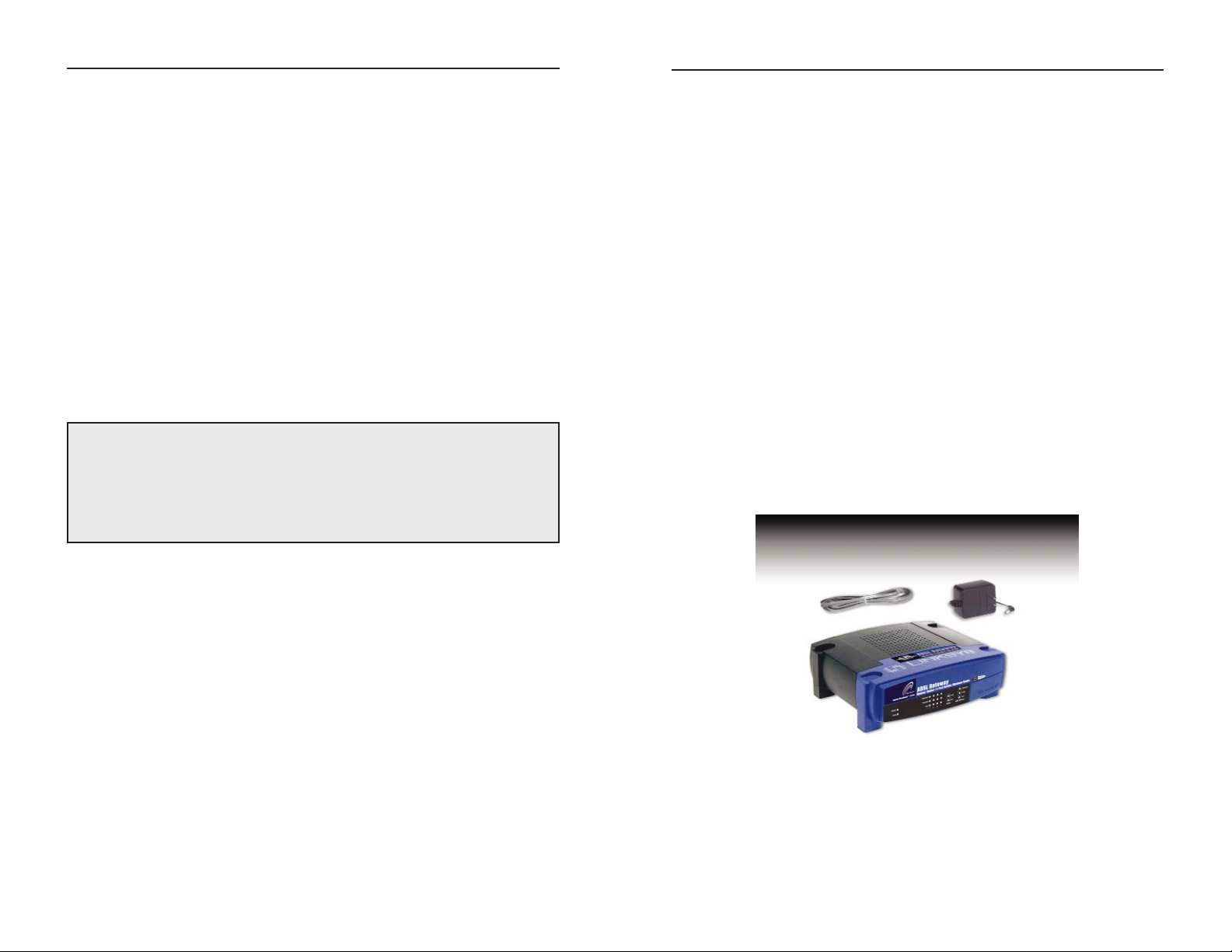
Package Contents
• One ADSL Gateway with Modem / Router / 4-Port Switch / Wireless-Ready
• One Power Adapter (adapter type varies by region)
• One RJ-11 Phone Cable
• One Quick Installation Guide (not shown)
4
Page 5
ADSL Gateway
with Modem / Router / 4-Port Switch / Wireless-Ready
7
Instant Broadband™ Series
6
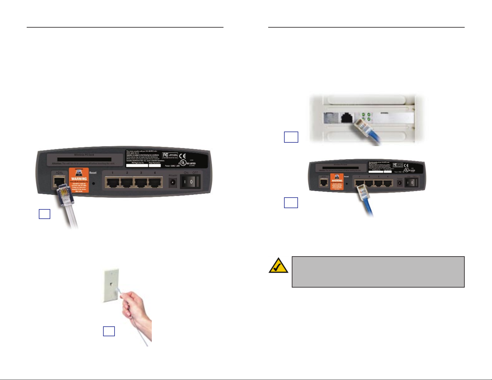
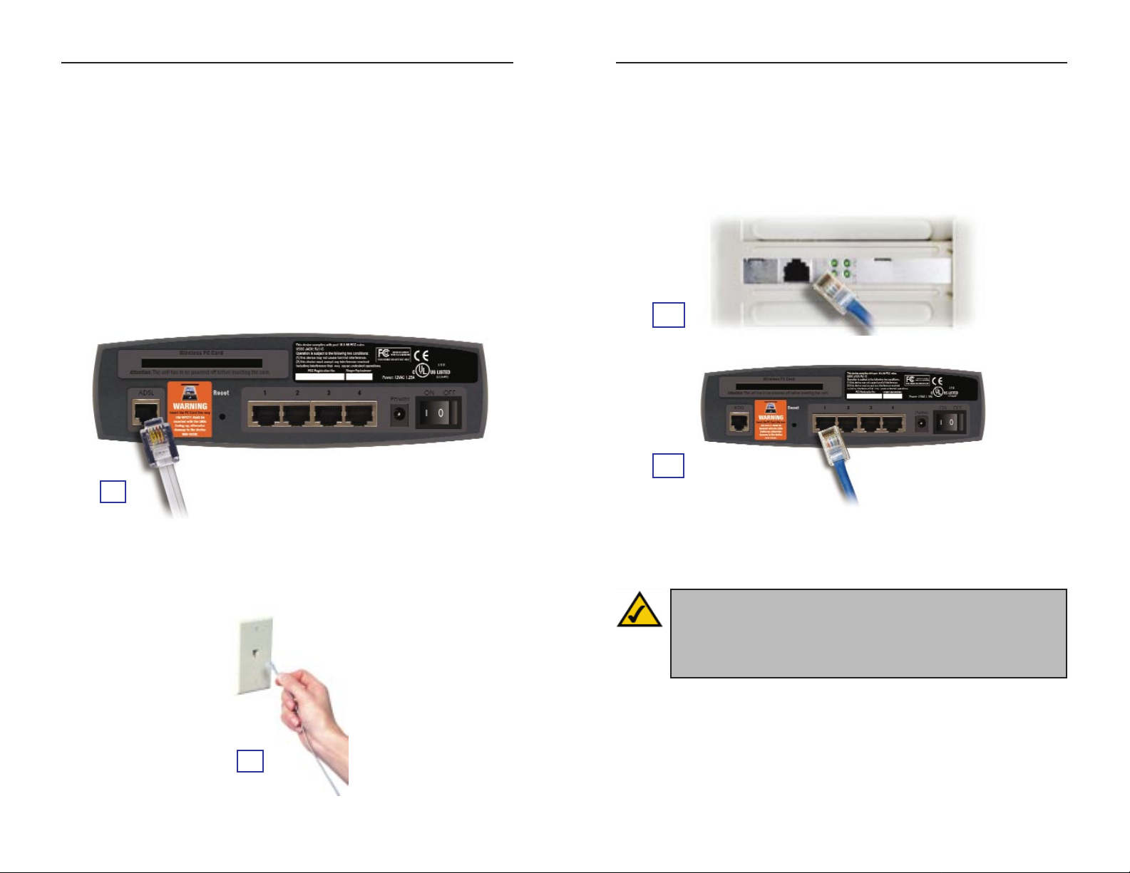
C. Connect one end of an Ethernet cable to your PC’s Ethernet adapter.
Connect the other end of the cable to one of the LAN ports on the back of
the Gateway. Repeat this process for every PC that you want to connect to
the Gateway.
Note: If your PC’s Ethernet adapter is not set up, refer to the Ethernet
adapter’s user guide for more information.
If you are connecting more than four PCs to the Gatew a y, you will also need
to connect a hub or switch to the Gateway.
C1
C
2
Note: If you have a Linksys Wireless PC Card (WPC11), be sure to
fully insert it into the PC Card slot on the back of the Gatewa y before
turning on the power. You must ha ve this card inserted in order to use
the Gateway’s wireless features.
Step 1:Connect the ADSL
Gateway
In Step 1, you will connect the Gateway to your ADSL line and to the computers in your home or business.
First, make sure that all the devices that you’ll be working with are powered
down, including your PCs and the Gateway.
A. Connect one end of the provided phone cable to the ADSL (RJ-11 phone)
port that is on the back of the Gateway.
B. Connect the other end of the phone cable to the wall jack with ADSLservice.
A
B
Page 6
ADSL Gateway
with Modem / Router / 4-Port Switch / Wireless-Ready
9
Instant Broadband™ Series
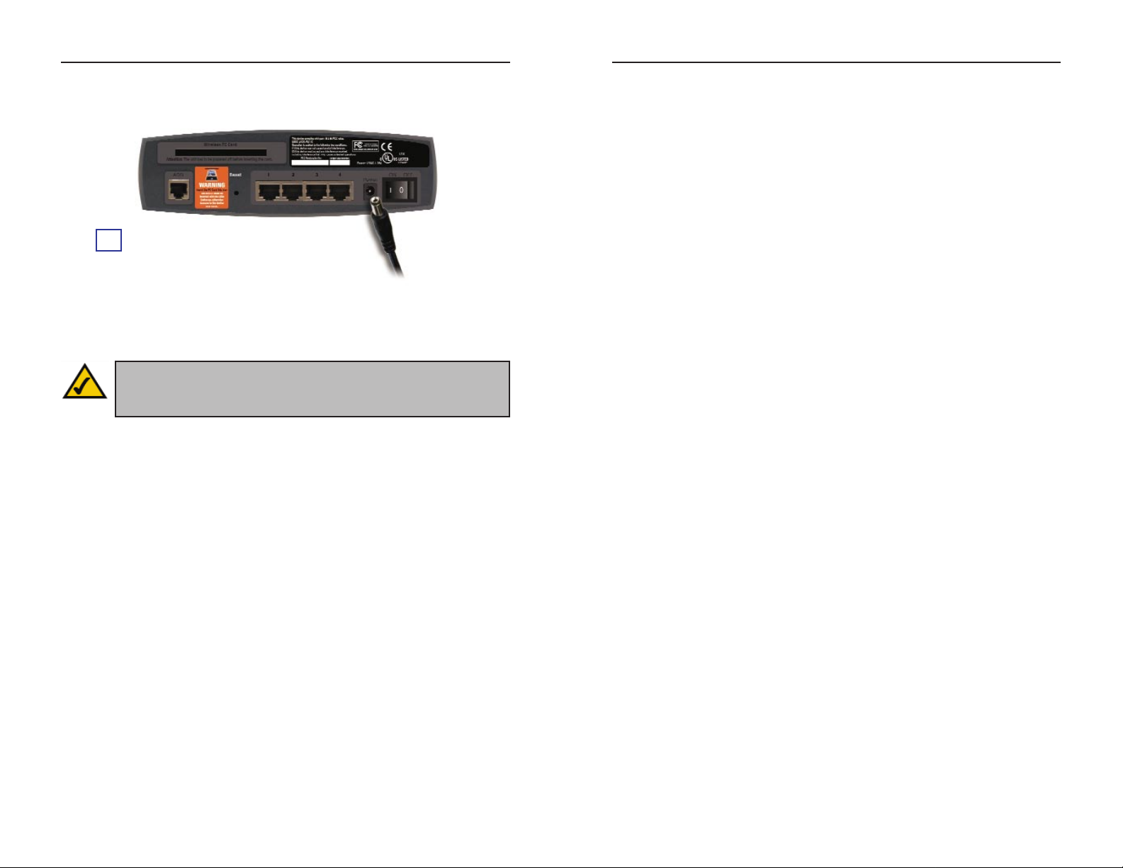
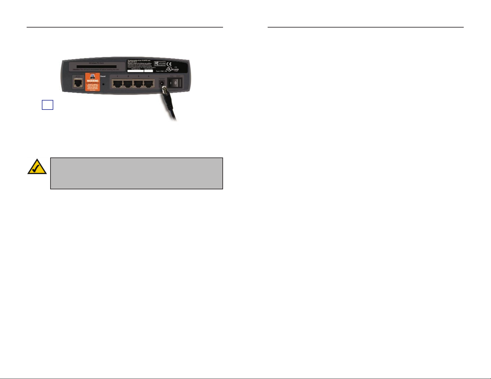
D. Connect to the power adapter to the Gateway. Connect the power adapter to
an electrical outlet.
E. Turn on your PCs and the Gateway.
Proceed to Step 2: Configure the PCs.
8
Step 2:Configure the PCs
In Step 2, you will configure each of your computers to be able to communicate with the Gateway.
T o do this, you need to configure your PC’s network settings to obtain an IP (or
TCP/IP) address automatically (this action is also referred to as DHCP).
Computers use IP addresses to communicate with each other across a network
or the Internet.
Find out which operating system your computer is running, such as Windows
95, 98, Millennium, 2000, or XP. One way to find out which operating system
you have is by clicking the Start button and then Settings. Click Control
Panel, and then double-click the System icon. Proceed to the section for the
operating system you are running on your PC.
If your operating system is not referenced here, refer to your operating system’s
documentation.
You may need to do this for each computer you are connecting to the Gateway.
The next few pages tell you, step by step, how to configure your network settings, depending on the type of W indows operating system you are using. Once
you’ ve configured your computers, continue to Step 3: Configure the Gatewa y.
D
Note: You may need to place a small device called a microfilter (not
included) between each phone and wall jack to prevent interference.
Contact your ISP if you have any questions.
Page 7
ADSL Gateway
with Modem / Router / 4-Port Switch / Wireless-Ready
D. Click the Gateway tab to ensure that the Installed Gateway field is blank.
Click the OK button.
E. Click the OK button again. Windows may ask you for the original
Windows installation disk or additional files. Supply them by pointing to
the correct file location, e.g., C:\windows\options\cabs, D:\win98,
D:\win9x, etc. (if “D” is the letter of your CD-ROM drive).
F. Windo ws may ask you to restart your PC. Click the Yes button. If W indows
does not ask you to restart, restart your computer anyway.
Proceed to Step 3: Configure the Gateway.
A. Click the Start button. Click Settings and then Control Panel. Double-
click the Network and Dial-up Connections icon.
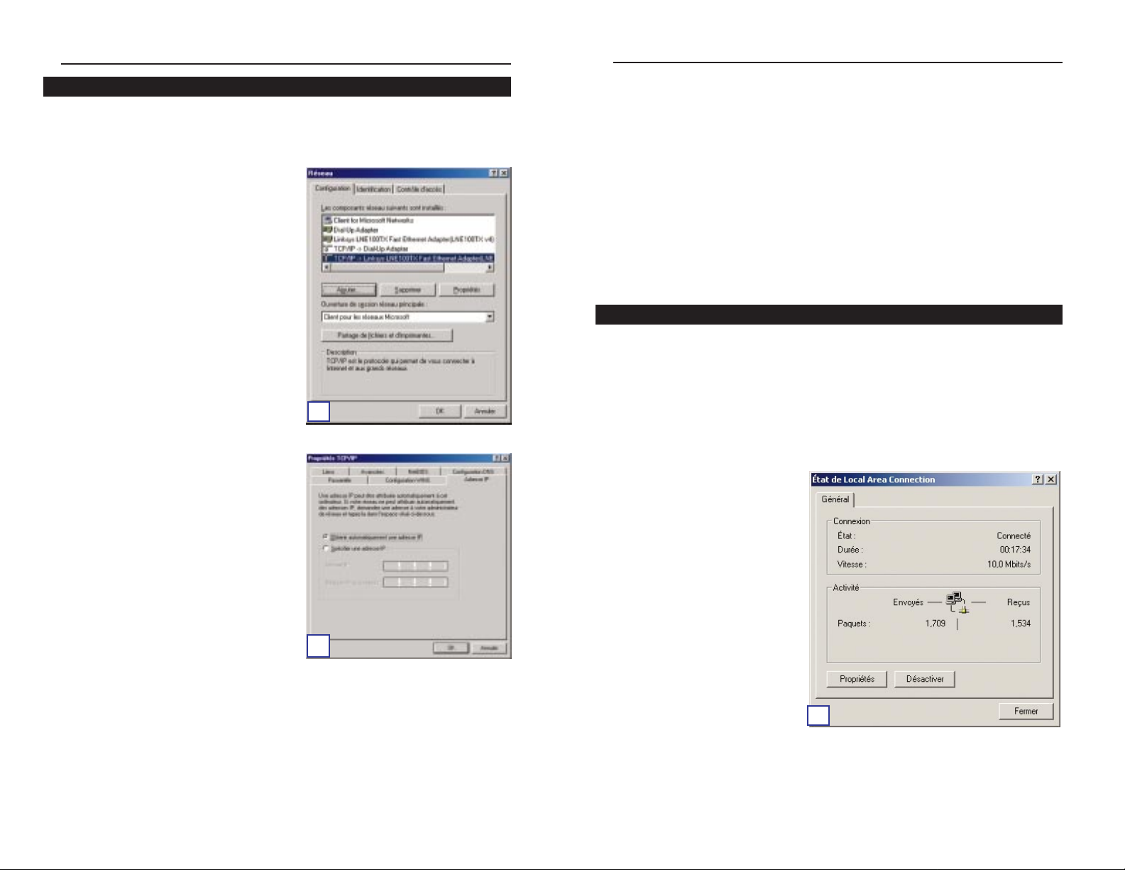
B. Select the Local Area Connection icon for the applicable Ethernet adapter
(usually it is the first Local Area Connection listed). Double-click the Local
Area Connection.
C. The Local Area Connection
Status screen will appear.
Click the Properties button.
11
Instant Broadband™ Series
10
Windows 2000 Instructions
C
A. Click the Start button. Click Settings and then Control Panel. Double-
click the Network icon.
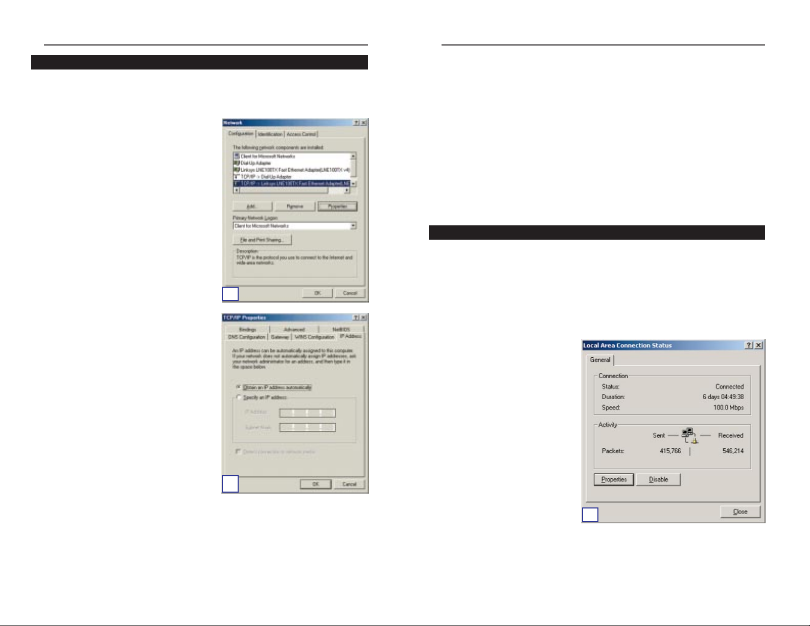
B. On the Configuration tab, select the
TCP/IP line for the applicable
Ethernet adapter. Do not choose a
TCP/IP entry whose name mentions
DUN, PPPoE, VPN, or AOL. If the
word TCP/IP appears by itself, select
that line. (If there is no TCP/IP line
listed, refer to your Ethernet adapter’s
user guide to install TCP/IP now.)
Click the Properties button.
C. Click the IP Address tab. Select
Obtain an IP address automatically.
Windows 95, 98, or Millennium Instructions
B
C
Page 8
ADSL Gateway
with Modem / Router / 4-Port Switch / Wireless-Ready
The following instructions assume you are running Windows XP with the
default interface. If you are using the Classic interface (its icons and menus
look like previous Windows versions), follow the instructions for Windows
2000.
A. Click the Start button. Click Settings and then Control Panel. Click the
Network and Internet Connections icon and then the Network
Connections icon.
B. Select the Local Area Connection icon for the applicable Ethernet adapter
(usually it is the first Local Area Connection listed). Double-click the Local
Area Connection.
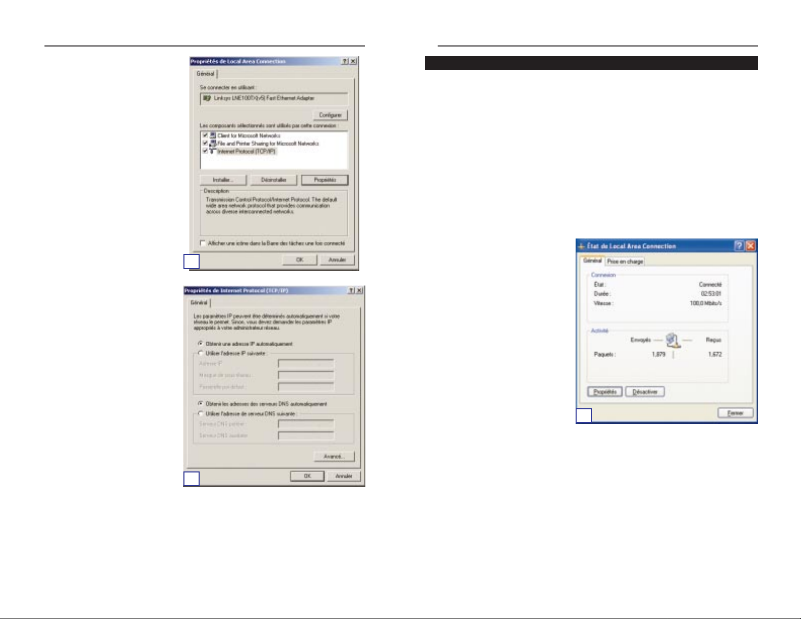
C. The Local Area Connection
Status screen will appear.
Click the Properties button.
13
Instant Broadband™ Series
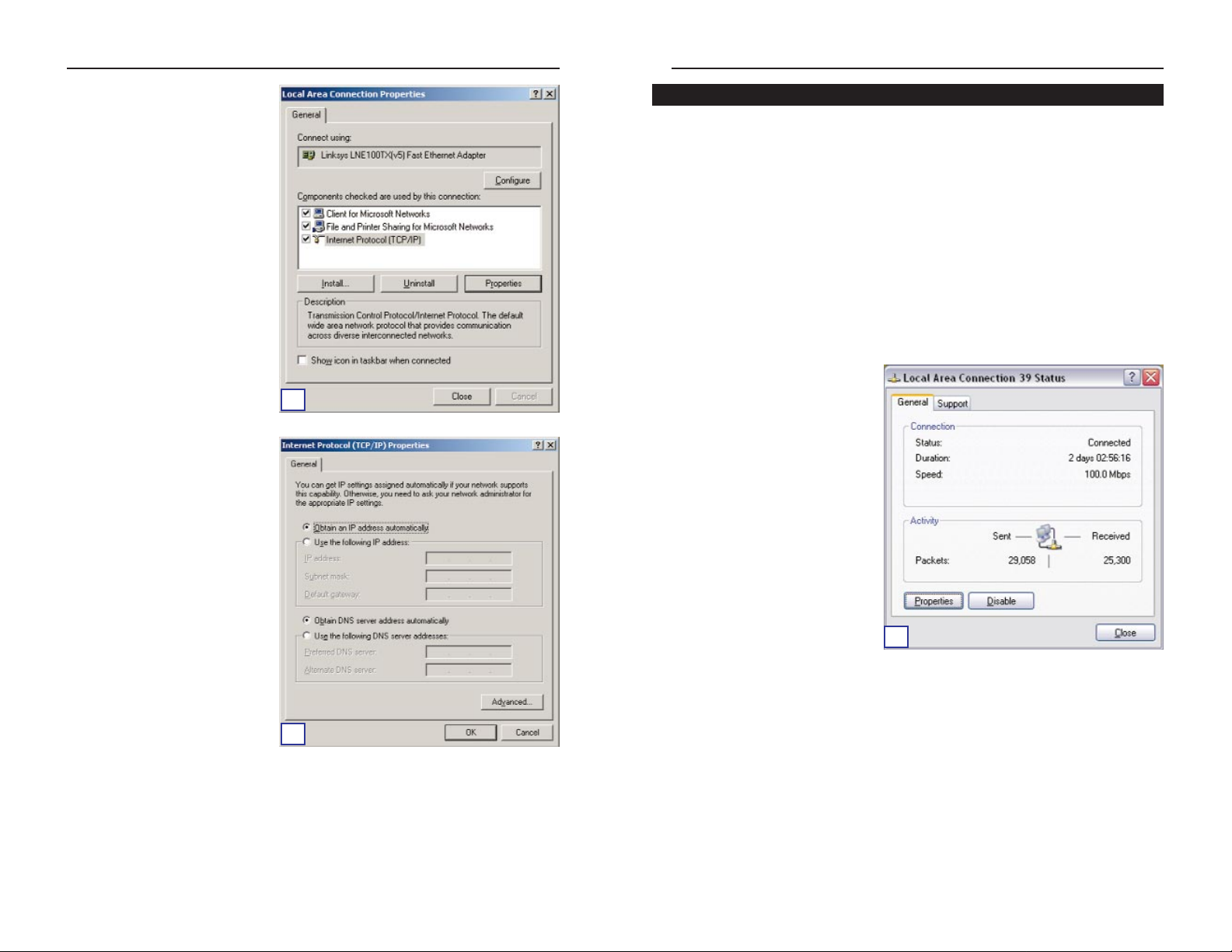
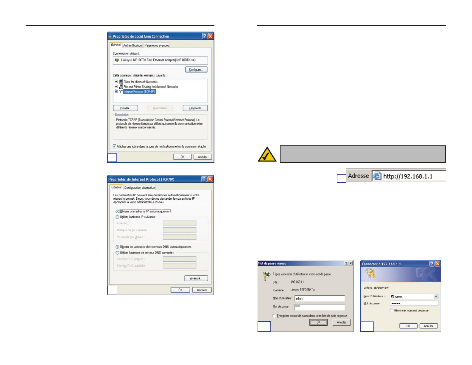
D. Select Internet Protocol
(TCP/IP), and click the
Properties button.
E. Select Obtain an IP address
automatically. When the
new window appears, click
the OKbutton. Click the OK
button again to complete the
PC configuration.
F. Restart your computer.
Proceed to Step 3: Configure the Gateway.
12
Windows XP Instructions
C
E
D
Page 9
ADSL Gateway
with Modem / Router / 4-Port Switch / Wireless-Ready
15
Instant Broadband™ Series
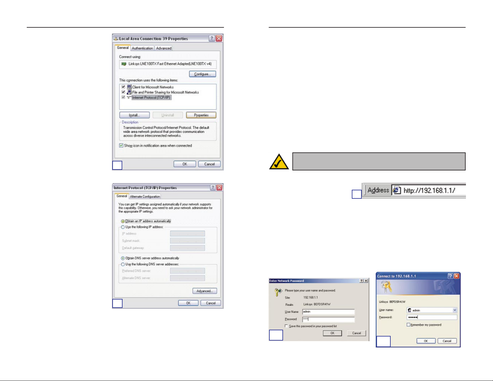
D. Select Internet Protocol
(TCP/IP), and click the
Properties button.
E. Select Obtain an IP address
automatically. When the
new window appears, click
the OKbutton. Click the OK
button again (or the Close
button if any settings were
changed) to complete the PC
configuration.
F. Restart your computer.
Proceed to Step 3: Configure the ADSL Gateway.
14
Step 3:Configure the ADSL
Gateway
In Step 3, you will configure the ADSL Gateway so it will be able to access the
Internet through your Internet Service Provider (ISP). You will need the setup
information provided by your ADSL ISP. If you do not have this information,
please contact them before proceeding.
The instructions from your ISP tell you how to set up your PC for Internet
access. Because you are now using the Gatewa y to share Internet access among
several computers, you will use the setup information to configure the Gateway
instead of your PC.
A. Open your web browser. (It
is all right if you get an error
message at this point.
Continue following these directions.) Enter http://192.168.1.1 in the web
browser’s Address field. Press the Enter key.
B. An Enter Network Password window, shown in Figure B
1, will appear
(Windows XP users will see a Connect to 192.168.1.1 window, shown in
Figure B
2). Enter admin in lowercase letters in the User Name field, and
enter admin in lowercase letters in the Password field (admin is the def ault
user name and password). Then click the OK button.
Note: You only need to configure the Gateway once using any computer you have set up.
A
B
1
B2
E
D
Page 10
ADSL Gateway
with Modem / Router / 4-Port Switch / Wireless-Ready
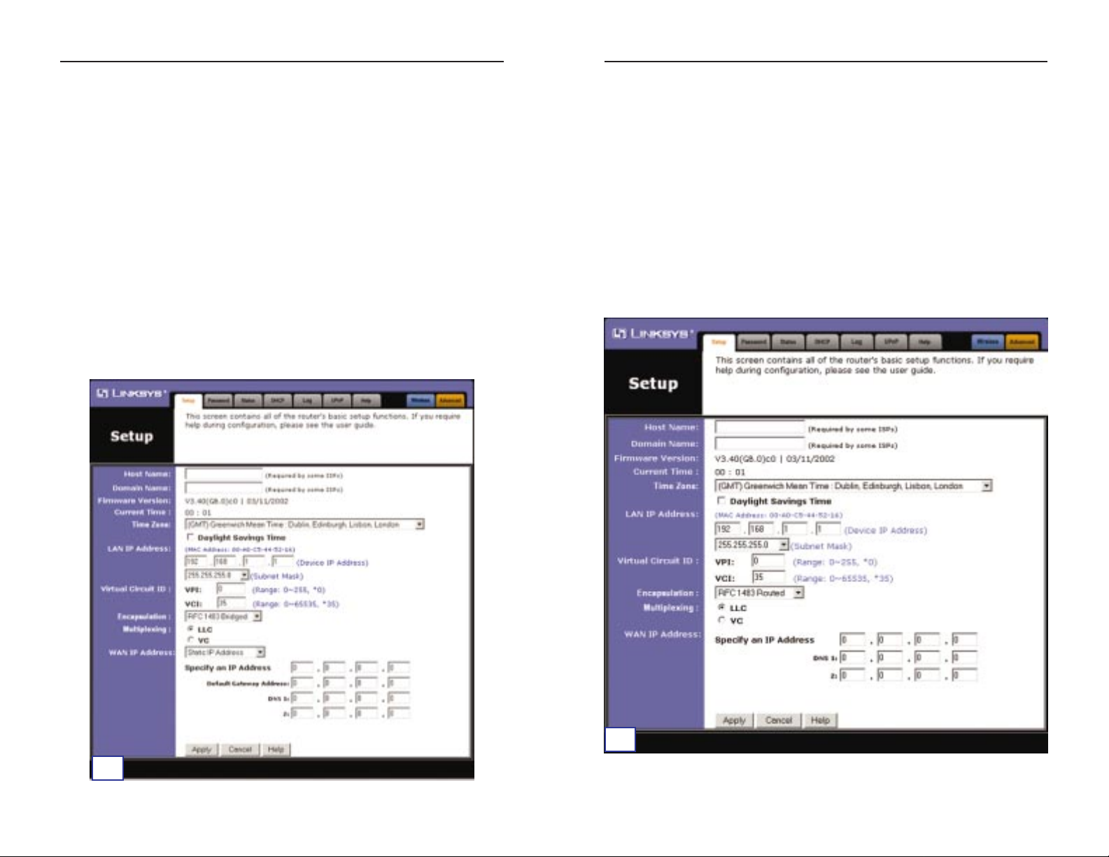
1. RFC 1483 Bridged
a. WAN IP Address: Dynamic IP Address
If your ISP says that y ou are connecting through a dynamic IP address, perform
these steps:
1. Select RFC 14583 Bridged.
2. Select Dynamic IP Address as the WAN IP Address.
3. Click the Apply and then the Continue buttons to save the settings.
17
Instant Broadband™ Series
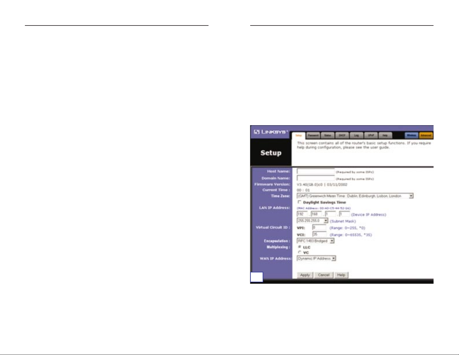
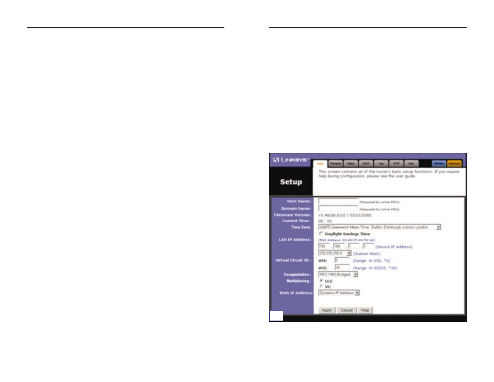
C. The Gateway configuration interface will appear with the Setup tab select-
ed. Based on the setup instructions from your ISP, you may need to provide
the following information.
Host Name and Domain Name: These fields allow you to provide a host
name and domain name for the Gatewa y. These fields are usually left blank.
If requested by your ISP, complete these two f ields.
Virtual Circuit ID(VPIand VCI): These fields consists of two items: VPI
(Virtual Path Identifier) and VCI (Virtual Channel Identifier). Your ISP will
provide the correct settings for each field.
D. Encapsulation: This Gateway supports five encapsulation modes: RFC
1483 Bridged, RFC 1483 Routed, RFC 2364 PPPoA, RFC2516 PPPoE,
and Bridged Mode Onl y. Each Setup screen and a v ailable features will dif-
fer depending on which mode you select. Your ISP will provide the correct
setting(s). Proceed to the instructions for the encapsulation mode you are
using.
16
D1
Page 11
ADSL Gateway
with Modem / Router / 4-Port Switch / Wireless-Ready
19
Instant Broadband™ Series
b. WAN IP Address: Static IP Address
If your ISP says that you are connecting through a static or fixed IP address
supplied by your ISP, perfor m these steps:
1. Select RFC 14583 Bridged.
2. Select Static IP Address as the WAN IP Address.
3. Enter the IP Address.
4. Enter the Default Gateway Address.
5. Enter the DNS in the 1 and/or 2 f ields. You must enter at least one DNS
address.
6. Click the Apply and then the Continue buttons to save the settings.
18
D2
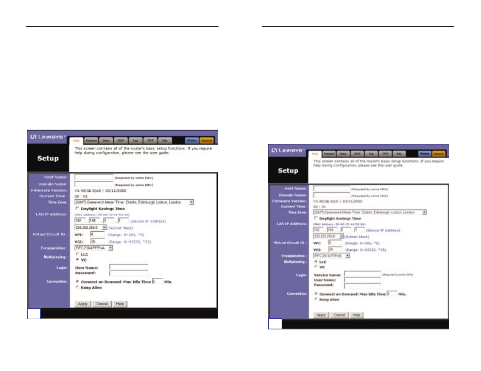
2. RFC 1483 Routed
If your ISP says that you are connecting through RFC 1483 Routed, perform
these steps:
a. Select RFC 1483 Routed.
b. Enter the IP Address.
c. Enter the DNS in the 1 and/or 2 fields. You must enter at least one DNS
address.
d. Click the Apply and then the Continue buttons to save the settings.
D3
Page 12
ADSL Gateway
with Modem / Router / 4-Port Switch / Wireless-Ready
4. RFC 2516 PPPoE
If your ISP says that you are connecting through RFC 2516 PPPoE, perform
these steps:
a. Select RFC 2516 PPPoE.
b. Enter the Service Name (if provided).
c. Enter the User Name.
d. Enter the Password.
e. Click the Apply and then the Continue buttons to save the settings.
21
Instant Broadband™ Series
3. RFC 2364 PPPoA
If your ISP says that you are connecting through RFC2364 PPPoA, perform
these steps:
a. Select RFC 2364 PPPoA.
b. Enter the User Name.
c. Enter the Password.
d. Click the Apply and then the Continue buttons to save the settings.
20
D4
D5
Page 13
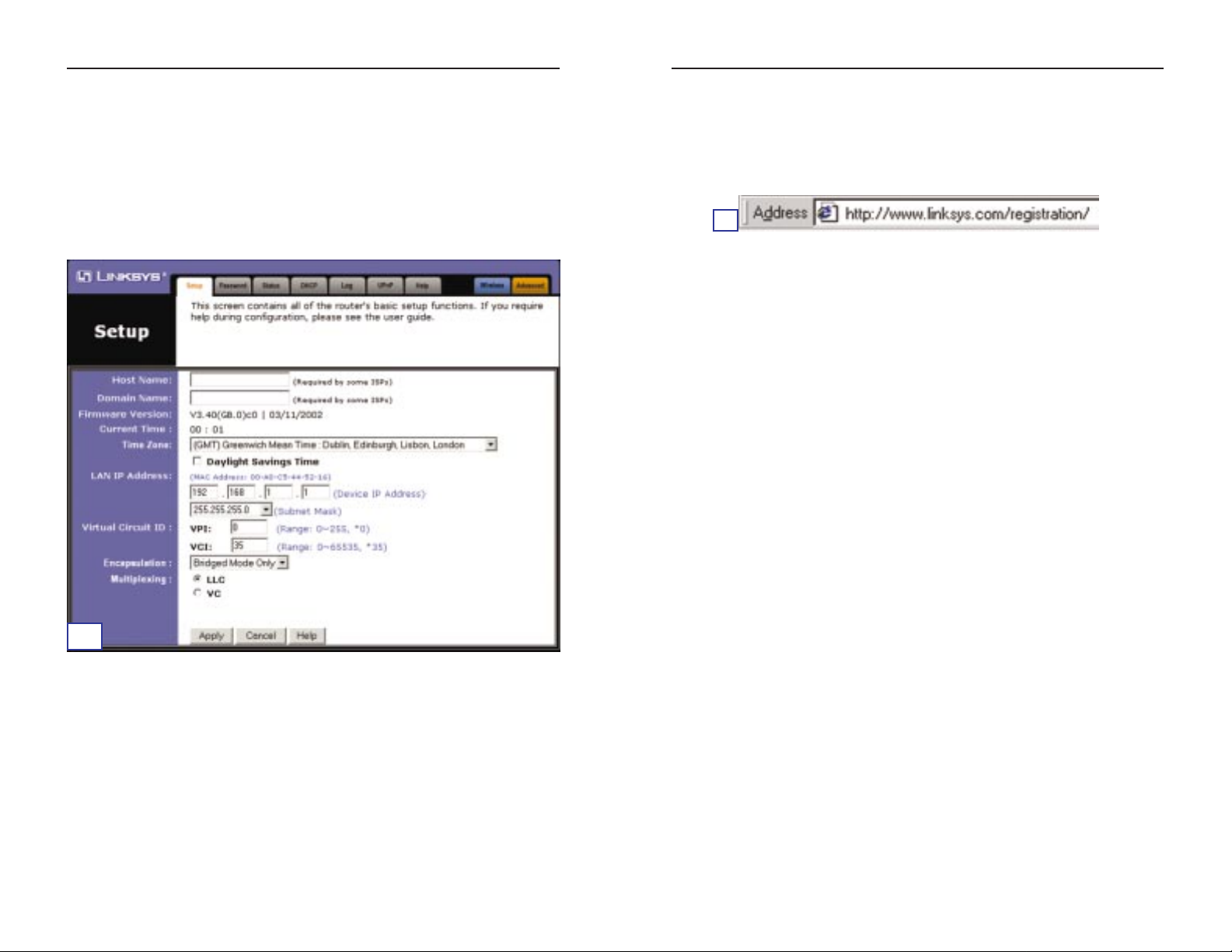
5. Bridged Mode Only
If your ISP says that you are connecting through Bridged Mode Only, perfor m
these steps:
a. Select Bridged Mode Only.
b. Click the Apply and then the Continue buttons to save the setting.
ADSL Gateway
with Modem / Router / 4-Port Switch / Wireless-Ready
E. If you haven’t already done so, click the Apply and then the Continue but-
tons to save your setup settings. Then close the web browser.
Test the setup by opening your web browser from any computer and entering http://www.linksys.com/registration.
Congratulations! You’ve successfully configured the Gateway.
If you are unable to reach our website, you may want to review what you
did in this section.
23
E
Instant Broadband™ Series
22
D6
Page 14

2524
COPYRIGHT & MARQUES DE COMMERCE
Copyright © 2002 Linksys. Tous droits réservés. Microsoft, Windows et le logo Windows
sont des marques déposées de Microsoft Corporation. Toutes les autres marques de commerce et tous les autres noms commerciaux appartiennent à leurs propriétaires respectifs.
AVIS DE CONFORMITÉ FCC, ARTICLE 15, CLASSE B
Conformément à la Federal Communications Commission (FCC), les règlements de
l’article 15 de la FCC suivants sont définis pour l’installation et l’utilisation de la passerelle
ADSL Linksys BEFDSR41W.
Les tests de conformité effectués sur cet appareil ont montrés qu’il respecte les limites fixées
pour un appareil numérique de classe B en vertu de l’article 15 des règlements de la FCC.
Ces limites sont conçues pour apporter une protection adéquate contre le brouillage
radioélectrique préjudiciable des installations résidentielles.
Cet équipement produit, utilise et peut émettre de l’énergie radioélectrique et peut, lorsqu’il
n’est pas installé et utilisé conformément aux instructions données, causer un brouillage
préjudiciable des radiocommunications. Cependant, rien ne garantit qu’une installation particulière ne produira pas de brouillage. Si l’appareil venait à causer un brouillage préjudiciable de la réception d’émissions radio ou télévisuelles, ce qui peut être déterminé en
l’éteignant et en le rallumant, nous vous conseillons d’essayer d’y remédier en prenant une
ou plusieurs des mesures suivantes :
• réorienter ou déplacer l’antenne de réception ;
• éloigner l’appareil du récepteur ;
• brancher l’appareil sur une prise située sur un autre circuit que celui auquel est connecté le récepteur ;
• consulter le revendeur ou un technicien de radiotélévision expérimenté.
Cet appareil est conforme à l’article 15 des règlements de la FCC. Son utilisation doit
respecter les deux conditions suivantes :
• Cet appareil ne peut pas provoquer d’interférences préjudiciables ;
• Cet appareil doit accepter les interférences reçues, notamment celles pouvant entraîner
un fonctionnement non désiré.
AVIS DE CONFORMITÉ FCC, ARTICLE 68
Cet appareil est conforme à l’article 68 des règlements de la FCC. Une étiquette apposée
sur l’appareil contient, entre autres, son numéro d’inscription auprès de la FCC ainsi que le
nombre équivalent de sonneries. Le cas échéant, il se peut que ces informations doivent être
fournies à l’opérateur téléphonique.
Cet appareil utilise la prise USOC suivante : RJ-11.
Un câble téléphonique et une fiche modulaire compatibles FCC sont fournis avec cet
appareil. Ce dernier est conçu pour être connecté au réseau téléphonique ou aux câblages
du bâtiment à l’aide d’une prise modulaire compatible conforme à l’article 68 de la FCC. La
connexion au réseau téléphonique doit être effectuée à l’aide de la prise téléphonique modulaire standard.
Le nombre équivalent de sonneries (REN) est utile pour déterminer combien de
périphériques peuvent être connectés à la ligne téléphonique tout en continuant à sonner en
cas d’appel du numéro de téléphone. Dans la plupart, mais pas la totalité, des régions, la
somme des REN doit être inférieure à 5. Pour être certain du nombre de périphériques maximum pouvant être connectés à la ligne, en fonction du nombre total de REN, contactez
l’opérateur téléphonique.
Si cet appareil est nuisible au réseau téléphonique, l’opérateur téléphonique peut annuler
temporairement votre service. S’il ne peut le prévenir préalablement, il avertira le client dès
que possible. En outre, vous serez informé de votre droit de porter plainte auprès de la FCC
si vous en ressentez la nécessité.
L’opérateur téléphonique peut apporter des modifications à ses installations, équipements,
opérations ou procédures susceptibles d’affecter le fonctionnement de votre appareil. Dans
ce cas, l’opérateur téléphonique vous en avertira au préalable pour vous permettre d’apporter les modifications nécessaires afin de maintenir un service ininterrompu.
Si cet appareil ne fonctionne pas correctement, déconnectez-le de la ligne téléphonique.
Essayez d’utiliser un autre appareil certifié par la FCC sur la même prise téléphonique. Si le
problème persiste, appelez le service de réparation de l’opérateur téléphonique. Dans le cas
contraire, si le problème semble être lié à cet appareil, déconnectez-le de la ligne téléphonique et ne l’utilisez plus tant qu’il n’est pas réparé. Remarquez que l’opérateur téléphonique peut vous demander de déconnecter l’appareil du réseau téléphonique jusqu’à ce
que le problème soit résolu ou que vous soyez certain qu’il ne fonctionne pas de manière
incorrecte. Pour obtenir des performances optimales, l’utilisateur doit utiliser les accessoires
et câbles fournis par le fabricant.
Aucune réparation ne peut être effectuée par le client. En cas de problème lié à cet appareil,
contactez le support technique agréé pour obtenir des informations sur la réparation et la
garantie. Si le problème nuit au réseau téléphonique, l’opérateur téléphonique peut vous
demander de retirer l’appareil du réseau jusqu’à sa résolution. Cet appareil ne peut pas être
utilisé dans les cabines téléphoniques payantes installées par l’opérateur téléphonique. La
connexion aux lignes partagées est soumise aux tarifs nationaux.
CONSIGNES DE SÉCURITÉ
• Attention : pour réduire le risque d’incendie, utilisez uniquement un câble de ligne de
communication AWG n° 26 ou plus grand.
• N’utilisez pas ce produit à proximité d’eau, par exemple dans une cave humide ou près
d’une piscine.
• Évitez d’utiliser ce produit (excepté le modèle sans fil) pendant un orage. Il existe un
risque d’électrocution, si faible soit-il, par la foudre.
Page 15
2726
Instant Broadband™Series
Table des matières
Configuration minimale 27
Contenu de l’emballage 27
Étape 1 : connexion de la passerelle ADSL 28
Étape 2 : configuration des PC 31
Instructions pour Windows 95, 98 ou Millennium 32
Instructions pour Windows 2000 33
Instructions pour Windows XP 35
Étape 3 : configuration de la passerelle ADSL 37
Passerelle ADSL avec modem/routeur/commutateur 4 ports/prêt pour des communications sans fil
Pour le support produit, l’enregistrement du produit et les informations sur la
garantie, contactez-nous aux adresses indiquées ci-dessous :
E-mail : europe-support@linksys.com
latam-soporte@linksys.com
Web : http://www.linksys.com/international
Configuration minimale
• Adaptateur réseau avec câblage Ethernet (UTP cat. 5) et protocole TCP/IP
installé sur chaque PC
• Internet Explorer 4.0 ou Netscape Navigator 4.7 ou supérieur pour une confi-
guration Web
• Connexion ADSL (annexe A uniquement) et compte activé
• Car te PC réseau sans f il en option, modèle WPC11, pour connexion sans f il
(vendue séparément)
Contenu de l’emballage
• Une passerelle ADSL avec modem/routeur/commutateur 4 ports/prêt pour
des communications sans fil
• Un adaptateur de courant (son type varie selon la région)
• Un câble téléphonique RJ-11
• Un Guide d’installation rapide (non présenté)
Page 16
2928
Passerelle ADSL avec modem/routeur/commutateur 4 ports/prêt pour des communications sans fil
Instant Broadband™Series
C. Branchez une extrémité d’un câble Ethernet sur l’adaptateur Ethernet du
PC. Branchez l’autre extrémité du câble sur l’un des ports de réseau local
situés à l’arrière de la passerelle. Recommencez cette opération pour
chaque PC à connecter à la passerelle.
Remarque : si l’adaptateur Ethernet du PC n’est pas installé, reportez-vous
à son Guide de l’utilisateur pour plus d’informations.
Si vous connectez plus de quatre PC à la passerelle, vous devez également
y connecter un hub ou un commutateur.
C1
C
2
Remarque : si vous disposez d’une carte PC sans fil Linksys
(WPC11), veillez à l’insérer complètement dans l’emplacement pour
carte PC situé à l’arrière de la passerelle avant de mettre l’appareil
sous tension. Cette carte doit être insérée pour pouvoir utiliser les
fonctions sans fil de la passerelle.
Étape 1 : connexion de la
passerelleADSL
À l’étape 1, vous allez connecter la passerelle à votre ligne ADSL et aux ordinateurs chez vous ou au bureau.
Vérifiez d’abord que tous les appareils que vous utiliserez sont hors tension,
notamment vos PC et la passerelle.
A. Connectez une extrémité du câble téléphonique fourni au port ADSL (port
téléphonique RJ-11) situé à l’arrière de la passerelle.
B. Branchez l’autre extrémité du câble téléphonique sur la prise murale équipée
du service ADSL.
A
B
Page 17
3130
Passerelle ADSL avec modem/routeur/commutateur 4 ports/prêt pour des communications sans fil
Instant Broadband™Series
D. Branchez l’adaptateur de courant sur la passerelle. Connectez l’adaptateur
de courant à une prise électrique.
E. Mettez les PC et la passerelle sous tension.
Passez à l’étape 2 : conf iguration des PC.
Étape 2 : configuration des PC
À l’étape 2, vous allez configurer chacun de vos ordinateurs pour pouvoir communiquer avec la passerelle.
Pour cela, vous devrez configurer les paramètres réseau du PC af in d’obtenir
automatiquement une adresse IP (ou TCP/IP). Cette action porte également le
nom de DHCP. Les ordinateurs emploient des adresses IP pour communiquer
entre eux sur un réseau ou sur Internet.
Identifiez le système d’exploitation utilisé sur votre ordinateur, par exemple
Windows 95, 98, Millennium, 2000 ou XP. Vous pouvez déterminer le système
d’exploitation que vous utilisez en cliquant sur le bouton Démarrer, puis sur
Paramètres. Cliquez sur Panneau de configuration, puis double-cliquez sur
l’icône Système. Passez à la section du système d’exploitation en cours d’exécution sur votre PC.
Si votre système d’exploitation n’est pas indiqué ici, reportez-vous à la documentation qui l’accompagne.
Vous devrez éventuellement suivre cette procédure pour chaque ordinateur à
connecter à la passerelle.
Les pages suivantes présentent la procédure pas à pas de configuration des
paramètres réseau en fonction du type de système d’exploitation Windows
employé. Une fois les ordinateurs configurés, passez à l’étape 3 : configuration de la passerelle.
D
Remarque :il se peut que vous deviez placer un petit appareil appelé
microfiltre (non four ni) entre chaque téléphone et chaque prise pour
éviter les brouillages. Pour toute question, contactez votre fournisseur de services Internet.
Page 18
3332
Passerelle ADSL avec modem/routeur/commutateur 4 ports/prêt pour des communications sans fil
D. Cliquez sur l’onglet Passerelle et vérif iez que le champ Passerelles instal-
lées est vide. Cliquez ensuite sur le bouton OK.
E. Cliquez de nouveau sur le bouton OK. Windows peut vous demander la
disquette d’installation Windows d’origine ou des fichiers supplémentaires. Indiquez leur emplacement, par exemple C:\windows\options\cabs,
D:\win98, D:\win9x, etc. (si « D » est la lettre du lecteur de CD-ROM).
F. Windows peut vous demander de redémarrer le PC. Cliquez sur le bouton
Oui. Même si Windows ne vous le demande pas, redémarrez quand même
l’ordinateur.
Passez à l’étape 3 : conf iguration de la passerelle.
A. Cliquez sur le bouton Démarrer. Cliquez sur Paramètres, puis sur
Panneau de configuration. Double-cliquez sur l’icône Connexions
réseau et accès à distance.
B. Sélectionnez l’icône Connexion au réseau localpour l’adaptateur Ethernet
concerné (il s’agit généralement de la première connexion au réseau local
répertoriée). Double-cliquez sur Connexion au réseau local.
C. L’écran État de la connexion
au réseau local apparaît.
Cliquez sur le bouton
Propriétés.
Instructions pour Windows 2000
C
Instant Broadband™Series
A. Cliquez sur le bouton Démarrer. Cliquez sur Paramètres, puis sur
Panneau de configuration. Double-cliquez sur l’icône Réseau.
B. Dans l’onglet Configuration, sélec-
tionnez la ligne TCP/IP de l’adaptateur Ethernet concerné. Ne choisissez
pas une entrée TCP/IP dont le nom
contient le terme DUN, PPPoE, VPN
ou AOL. Si le mot TCP/IP apparaît
seul, sélectionnez cette ligne. (Si
aucune ligne TCP/IP n’est répertoriée, reportez-vous au Guide de
l’utilisateur de l’adaptateur Ethernet
pour installer TCP/IP maintenant.)
Cliquez sur le bouton Propriétés.
C. Cliquez sur l’onglet Adresse IP.
Sélectionnez Obtenir une adresse IP
automatiquement.
Instructions pour Windows 95, 98 ou Millennium
B
C
Page 19
3534
Passerelle ADSL avec modem/routeur/commutateur 4 ports/prêt pour des communications sans fil
Les instructions suivantes partent du principe que vous utilisez l’interface par
défaut de Windows XP. Si vous utilisez l’interface classique (dans laquelle les
icônes et les menus ressemblent à ceux des versions précédentes de Windows),
suivez les instructions fournies pour Windows 2000.
A. Cliquez sur le bouton Démarrer. Cliquez sur Paramètres, puis sur
Panneau de configuration. Cliquez sur l’icône Connexions réseau et
Internet, puis sur l’icône Connexions réseau.
B. Sélectionnez l’icône Connexion au réseau localpour l’adaptateur Ethernet
concerné (il s’agit généralement de la première connexion au réseau local
répertoriée). Double-cliquez sur Connexion au réseau local.
C. L’écran État de la connexion
au réseau local apparaît.
Cliquez sur le bouton
Propriétés.
Instant Broadband™Series
D. Sélectionnez Protocole
Internet (TCP/IP) et
cliquez sur le bouton
Propriétés.
E. Sélectionnez Obtenir une
adresse IP automatiquement. Lorsque la nouvelle
fenêtre apparaît, cliquez sur
le bouton OK. Cliquez de
nouveau sur le bouton OK
pour achever la configuration du PC.
F. Redémarrez l’ordinateur.
Passez à l’étape 3 : conf iguration de la passerelle.
Instructions pour Windows XP
C
E
D
Page 20
3736
Passerelle ADSL avec modem/routeur/commutateur 4 ports/prêt pour des communications sans fil
Instant Broadband™Series
D. Sélectionnez Protocole
Internet (TCP/IP) et
cliquez sur le bouton
Propriétés.
E. Sélectionnez Obtenir une
adresse IP automatiquement. Lorsque la nouvelle
fenêtre apparaît, cliquez sur
le bouton OK. Cliquez de
nouveau sur le bouton OK
(ou sur le bouton Fermer si
vous avez modifié certains
paramètres) pour achever la
configuration du PC.
F. Redémarrez l’ordinateur.
Passez à l’étape 3 : conf iguration de la passerelle ADSL.
Étape 3 : configuration de la
passerelleADSL
À l’étape 3, vous allez configurer la passerelle ADSL pour pouvoir accéder à
Internet à l’aide de votre fournisseur d’accés Internet (FAI). Vous aurez besoin des
informations de configuration fournies par votre fournisseur ADSL. Si vous ne disposez pas de ces informations, veuillez le contacter avant de continuer.
Les instructions de votre fournisseur d’accés Internet indiquent comment conf igurer votre PC pour un accès Internet. Comme vous utilisez maintenant la
passerelle pour partager un accès Internet entre plusieurs ordinateurs, vous aurez
besoin de ces informations pour conf igurer la passerelle plutôt que votre PC.
A. Ouvrez le navigateur Web.
(Il est normal d’obtenir un
message d’erreur à ce stade.
Continuez à suivre ces instructions.) Entrez http://192.168.1.1 dans le champ
Address (Adresse) de votre navigateur Web. Appuyez sur la touche Entrée.
B. Une fenêtre Enter Network Password (Mot de passe réseau), présentée à la
figure B1, apparaît (les utilisateurs de Windows XP verront une fenêtre
Connect to 192.168.1.1 (Connexion 192.168.1.1), présentée à la figure B2).
Entrez admin en minuscules dans les champs User Name (Nom d’utilisateur) et Password (Mot de passe) (admin est le nom d’utilisateur et le mot
de passe par défaut). Cliquez ensuite sur le bouton OK.
Remarque : vous ne devez configurer la passerelle qu’à une seule
reprise à l’aide de l’ordinateur que vous avez configuré.
A
B
1
E
D
B2
Page 21
3938
Passerelle ADSL avec modem/routeur/commutateur 4 ports/prêt pour des communications sans fil
1. RFC 1483 Bridged (RFC 1483 ponté)
a. WAN IP Address (Adresse IP WAN) : Dynamic IP Address (Adresse IP
dynamique)
Si votre fournisseur
d’accés
Internet indique que vous vous connectez par l’in-
termédiaire d’une adresse IP dynamique, procédez comme suit :
1. Sélectionnez RFC 14583 Bridged (RFC 14583 ponté).
2. Sélectionnez Dynamic IP Address (Adresse IP dynamique) pour WAN IP
Address (Adresse IP WAN).
3. Cliquez sur les boutons Apply (Appliquer) et Continue (Continuer) pour
enregistrer les paramètres.
Instant Broadband™Series
C. L’interface de configuration de la passerelle apparaît avec l’onglet Setup
(Configuration) sélectionné. Selon les instructions de configuration de
votre fournisseur
d’accés
Internet, il se peut que vous deviez fournir les
informations suivantes.
Host Name (Nom d’hôte) et Domain Name (Nom de domaine) : ces
champs vous permettent de fournir un nom d’hôte et un nom de domaine
pour la passerelle. Ils sont généralement laissés vides. Si votre fournisseur
de ser-vices Internet l’exige, renseignez-les.
Virtual Circuit ID (ID de circuit vir tuel) (VPI et VCI) : ces champs sont
constitués de deux éléments : VPI (Virtual Path Identifier) et VCI (Virtual
Channel Identifier). Votre fournisseur
d’accés
Internet fournit les
paramètres corrects pour chaque champ.
D. Encapsulation : cette passerelle prend en charge cinq modes d’encapsu-
lation : RFC 1483 Bridged (RFC 1483 ponté), RFC 1483 Routed (RFC
1483 routé), RFC 2364 PPPoA, RFC 2516 PPPoE et Bridged Mode Only
(Mode ponté uniquement). Les écrans et fonctions de configuration
disponibles varient selon le mode sélectionné. Votre fournisseur
d’accés
Internet fournit les paramètres cor rects. Passez aux instructions correspondant au mode d’encapsulation que vous utilisez.
D1
Page 22

4140
Passerelle ADSL avec modem/routeur/commutateur 4 ports/prêt pour des communications sans fil
Instant Broadband™Series
b. WAN IP Address (Adresse IP WAN) : Static IP Address (Adresse IP per-
manente)
Si votre fournisseur
d’accés
Internet indique que vous vous connectez par l’in-
termédiaire d’une adresse IP permanente ou fixe, procédez comme suit :
1. Sélectionnez RFC 14583 Bridged (RFC 14583 ponté).
2. Sélectionnez Static IP Address (Adresse IP permanente) pour WAN IP
Address (Adresse IP WAN).
3. Renseignez le champ IP Address (Adresse IP).
4. Renseignez le champ Default Gateway Address(Adresse de passerelle par
défaut).
5. Entrez l’adresse DNS dans les champs 1 et/ou 2. Vous devez entrer au
moins une adresse DNS.
6. Cliquez sur les boutons Apply (Appliquer) et Continue (Continuer) pour
enregistrer les paramètres.
D2
2. RFC 1483 Routed (RFC 1483 routé)
Si votre fournisseur d’accés Internet indique que vous vous connectez par
l’intermédiaire de RFC 1483 Routed (RFC 1483 routé), procédez comme suit :
a. Sélectionnez RFC 1483 Routed (RFC 1483 routé).
b. Renseignez le champ IP Address (Adresse IP).
c. Entrez l’adresse DNS dans les champs 1 et/ou 2. Vous devez entrer au
moins une adresse DNS.
d. Cliquez sur les boutons Apply (Appliquer) et Continue (Continuer) pour
enregistrer les paramètres.
D3
Page 23

4342
Passerelle ADSL avec modem/routeur/commutateur 4 ports/prêt pour des communications sans fil
4. RFC 2516 PPPoE
Si votre fournisseur
d’accés
Internet indique que vous vous connectez par l’in-
termédiaire de RFC 2516 PPPoE, procédez comme suit :
a. Sélectionnez RFC 2516 PPPoE.
b. Renseignez le champ Service Name (Nom du service) éventuel.
c. Renseignez le champ User Name (Nom d’utilisateur).
d. Renseignez le champ Password (Mot de passe).
e. Cliquez sur les boutons Apply (Appliquer) et Continue (Continuer) pour
enregistrer les paramètres.
Instant Broadband™Series
3. RFC 2364 PPPoA
Si votre fournisseur
d’accés
Internet indique que vous vous connectez par l’in-
termédiaire de RFC 2364 PPPoA, procédez comme suit :
a. Sélectionnez RFC 2364 PPPoA.
b. Renseignez le champ User Name (Nom d’utilisateur).
c. Renseignez le champ Password (Mot de passe).
d. Cliquez sur les boutons Apply (Appliquer) et Continue (Continuer) pour
enregistrer les paramètres.
D4
D5
Page 24

4544
5. Bridged Mode Only (Mode ponté uniquement)
Si votre fournisseur
d’accés
Internet indique que vous vous connectez par l’intermédiaire de Bridged Mode Only (Mode ponté uniquement), procédez
comme suit :
a. Sélectionnez Bridged Mode Only (Mode ponté uniquement).
b. Cliquez sur les boutons Apply (Appliquer) et Continue (Continuer) pour
enregistrer les paramètres.
Passerelle ADSL avec modem/routeur/commutateur 4 ports/prêt pour des communications sans fil
E. Si vous n’avez pas encore effectué cette opération, cliquez sur les boutons
Apply(Appliquer) et Continue (Continuer) pour enregistrer les paramètres
de configuration. Fermez ensuite le navigateur Web.
Testez la configuration en ouvrant votre navigateur Web à partir d’un ordinateur et en entrant http://www.linksys.com/registration.
Félicitations ! La conf iguration de la passerelle est terminée.
Si vous ne parvenez pas à accéder à notre site Web, il se peut que vous
souhaitiez consulter à nouveau les procédures de cette section.
E
Instant Broadband™Series
D6
Page 25

4746
COPYRIGHT & MARKEN
Copyright © 2002 Linksys. Alle Rechte vorbehalten. Microsoft, Windows und das WindowsLogo sind eingetragene Marken der Microsoft Corporation. Alle anderen Marken und
Markennamen sind Eigentum der jeweiligen Firmen.
FCC-KONFORMITÄTSERKLÄRUNG
Gemäß Verordnung der Federal Communications Commission (FCC) werden im folgenden
die FCC-Vorschriften des Abschnitts 15 für die Installation und Betrieb des Linksys ADSLGateways BEFDSR41W wiedergegeben.
Dieses Gerät wurde nach Maßgabe der Grenzwerte von Abschnitt 15 der FCC-Vorschriften
geprüft und als digitales Gerät der Klasse B eingestuft. Zweck dieser Grenzwerte ist es, für
angemessenen Schutz vor schädlichen Störungen im Umfeld einer Privatinstallation zu sorgen.
Dieses Gerät erzeugt und verwendet Funkfrequenzenergie und kann diese ausstrahlen. Bei
unsachgemäßer Installation und Verwendung kann es Störungen des Funkverkehrs verursachen. Es kann nicht grundsätzlich ausgeschlossen werden, dass in bestimmten
Installationen Störungen auftreten. Für den Fall, dass das Gerät Störungen des Funk- oder
Fernsehempfangs auslöst, die sich durch Aus- und Einschalten des Geräts feststellen
lassen, wird dem Benutzer empfohlen, die Störung durch eine oder mehrere der folgenden
Maßnahmen zu beseitigen:
• Antenne neu ausrichten oder an einem anderen Ort aufstellen
• Abstand des Empfängers zum Gerät erhöhen
• Empfänger und Gerät an getrennten Stromkreisen anschließen
• Händler oder erfahrenen Radio/TV-Fachmann hinzuziehen
Dieses Gerät ist konform mit Abschnitt 15 der FCC-Vorschriften. Der Betrieb ist nur unter
den beiden folgenden Bedingungen zulässig:
• Dieses Gerät darf keine schädliche Störstrahlung verursachen.
• Dieses Gerät darf durch aufgenommene Störstrahlung nicht beschädigt werden, auch
wenn diese möglicherweise Betriebsstörungen verursacht.
FCC-ERKLÄRUNG ZU ABSCHNITT 68
Dieses Gerät ist konform mit Abschnitt 68 der FCC-Vorschriften. Auf dem Gerät ist ein Etikett
angebracht, das u. a. die FCC-Registrierungsnummer und die REN (Ringer Equivalence
Number) enthält. Diese Angaben müssen Ihrer Telefongesellschaft auf Anfrage mitgeteilt werden.
Dieses Gerät weist die folgende USOC-Steckverbindung auf: RJ-11.
Das Gerät wird mit einem FCC-konformen Telefonkabel mit modularen Steckern geliefert.
Das Gerät ist für den Anschluss an das Telefonnetz oder die Gebäudeinstallation unter
Verwendung eines kompatiblen, modularen Steckers (konform zu FCC Abschnitt 68) konzipiert. Der Anschluss an das Telefonnetz sollte unter Verwendung der modularen StandardTelefonsteckverbindung erfolgen.
Die Ringer Equivalence Number (REN) gibt die maximale Anzahl der Geräte an, die an eine
Telefonleitung angeschlossen werden können und bei der noch alle Geräte einen Anruf sicher durch Läuten melden. In den meisten Fällen sollte die REN nicht über fünf liegen. Die
zulässige Anzahl der Geräte, die in Ihrem Rufnummernbereich an die Leitung angeschlossen
werden können, können Sie bei Ihrer Telefongesellschaft erfragen.
Wenn dieses Gerät die Funktion des Telefonnetzes beeinträchtigt, wird Ihre Telefongesellschaft Ihren Anschluss möglicherweise vorübergehend sperren. Eine Benachrichtigung
des Kunden über eine solche Sperrung erfolgt unter Umständen erst im Nachhinein. Dabei
werden Sie auch über Ihr Einspruchsrecht belehrt.
Ihre Telefongesellschaft kann ihre Einrichtungen, Anlagen, Betriebsarten oder -verfahren
möglicherweise ändern, wodurch sich Auswirkungen auf den Betrieb der Endgeräte
ergeben. Solche Änderungen teilt Ihnen Ihre Telefongesellschaft vorab mit, damit Sie die
erforderlichen Änderungen ohne Betriebsunterbrechung durchführen können.
Sollte dieses Gerät nicht ordnungsgemäß funktionieren, trennen Sie es von der
Telefonleitung. Schließen Sie an derselben Telefonbuchse ein anderes zugelassenes Gerät
an. Sollte der Fehler fortbestehen, teilen Sie dies der Störungsstelle Ihrer Telefongesellschaft
mit. Ist der Fehler nun behoben und damit auf das erste Gerät eingegrenzt, trennen Sie
dieses von der Telefonleitung, und verwenden Sie es erst wieder, nachdem eine Reparatur
erfolgt ist. Ihre Telefongesellschaft kann Sie verpflichten, das Gerät vom Telefonnetz zu trennen, bis das Problem behoben wurde oder bis die einwandfreie Funktion des Geräts
sichergestellt ist. Der Benutzer muss die vom Hersteller gelieferten Komponenten und Kabel
verwenden, damit das Produkt optimal funktioniert.
Vom Kunden selbst dürfen keine Reparaturen durchgeführt werden. Sollten sich mit diesem
Gerät Probleme einstellen, wenden Sie sich an eine autorisierte Kundendienststelle, um eine
Reparatur durchführen zu lassen oder die Gewährleistung in Anspruch zu nehmen. Falls der
Schaden am Gerät Beeinträchtigungen des Telefonnetzes zur Folge hat, wird Ihre
Telefongesellschaft Sie möglicherweise dazu auffordern, das Gerät bis zur Behebung des
Problems vom Netz zu nehmen. Dieses Gerät kann nicht im Münztelefondienst eingesetzt
werden. Der Anschluss an den Gruppenverbindungsdienst unterliegt festgesetzten Tarifen.
SICHERHEITSHINWEISE
• Vorsicht: Zur Vermeidung von Feuergefahr dürfen nur Telefonleitungen mit einem
Drahtdurchmesser von 0,4 mm (AWG 26) oder größer verwendet werden.
• Dieses Produkt darf nicht in Feuchtbereichen wie Kellerräumen oder Bädern eingesetzt
werden.
• Dieses Produkt sollte (im Gegensatz zu kabellosen Ausführungen) nicht während eines
Gewitters verwendet werden. Es besteht ein gewisses Verletzungsrisiko durch
Blitzschlag.
Page 26

4948
Instant Broadband™-Serie
Inhaltsverzeichnis
Minimale Anforderungen 49
Verpackungsinhalt 49
Schritt 1: Anschließen des ADSL-Gateways 50
Schritt 2: Konfigurieren der PCs 53
Anweisungen für Windows 95, 98 und Me 54
Anweisungen für Windows 2000 55
Anweisungen für Windows XP 57
Schritt 3: Konfigurieren des ADSL-Gateways 59
ADSL-Gateway mit Modem / Router / 4-Port-Switch / Wireless-fähig
Informationen zur Produktunterstützung, Produktregistrierung und
Gewährleistung erhalten Sie unter den folgenden Adressen:
E-Mail europe-support@linksys.com
latam-soporte@linksys.com
Web http://www.linksys.com/international
Minimale Anforderungen
• Eine Netzwerkkarte mit Ethernetkabel (UTP CAT5) und TCP/IP-Protokoll
pro PC
• Inter net Explorer 4.0 bzw. Netscape Navigator 4.7 oder höher für die web-
basierte Konfiguration
• ADSL-Verbindung (nur Annex A) und aktiviertes Konto
• Optionale Wireless PC-Netzwerkkarte, Modell WPC11, für kabellose
Verbindungen (separat erhältlich)
Verpackungsinhalt
• Ein ADSL-Gateway mit Modem / Router / 4-Port-Switch / Wireless-fähig
• Ein Netzteil (Ausführ ung länderspezifisch)
• Ein RJ-11-Telefonkabel
• Eine Installationsanleitung (nicht abgebildet)
Page 27

5150
ADSL-Gateway mit Modem / Router / 4-Port-Switch / Wireless-fähigInstant Broadband™-Serie
C. Schließen Sie ein Ethernet-Kabel an die Ethernet-Karte Ihres PCs an.
Schließen Sie das andere Ende des Kabels an einen der LAN-Ports auf der
Rückseite des Gateways an. Wiederholen Sie diesen Vorgang für jeden weiteren PC, den Sie an das Gateway anschließen möchten.
Hinweis: Ist die Ethernet-Karte Ihres PCs nicht eingerichtet, finden Sie
weitere Informationen im Benutzerhandbuch der Ethernet-Karte.
Wenn Sie mehr als vier PCs an das Gateway anschließen möchten, müssen
Sie an das Gateway zusätzlich einen Hub oder Switch anschließen.
C1
C
2
Hinweis: Wenn Sie eine Wireless PC-Karte von Linksys verwenden
(WPC11), ist darauf zu achten, dass diese im PC-Kartensteckplatz
auf der Rückseite des Gateways vollständig eingesteckt ist, bev or das
Gatewa y eingeschaltet wird. Diese Karte muss installiert sein, um die
Wireless-Funktionen des Gateways verwenden zu können.
Schritt 1:Anschließen des ADSLGateways
In Schritt 1 verbinden Sie das Gateway mit Ihrer ADSL-Leitung und Ihren privaten oder geschäftlichen Computern.
Vergewissern Sie sich zunächst, dass alle Geräte, mit denen Sie arbeiten werden, also die PCs und das Gateway, ausgeschaltet sind.
A. Schließen Sie ein Ende des mitgelieferten Telefonkabels an den ADSL-Port
(RJ-11-Telefonbuchse) an der Rückseite des Gateways an.
B. Schließen Sie das andere Ende des Telefonkabels an die Wandsteckdose an,
über die der ADSL-Dienst bereitgestellt wird.
A
B
Page 28

5352
ADSL-Gateway mit Modem / Router / 4-Port-Switch / Wireless-fähigInstant Broadband™-Serie
D. Schließen Sie das Netzgerät am Gateway an. Schließen Sie das Netzgerät
an einer Netzsteckdose an.
E. Schalten Sie Ihre PCs und das Gateway ein.
Fahren Sie mit Schritt 2 fort: Konfigurieren der PCs.
Schritt2:Konfigurieren der PCs
In Schritt 2 werden Sie die einzelnen Computer für die Kommunikation mit
dem Gateway konfigurieren.
Hierzu müssen Sie die Netzwerkeinstellungen Ihres PCs so einstellen, dass
eine IP-Adresse (auch TCP/IP-Adresse genannt) automatisch bezogen wird
(durch Aktivieren der DHCP-Option). Computer verwenden IP-Adressen zur
gegenseitigen Kommunikation über ein Netzwerk oder das Internet.
Ermitteln Sie, unter welchem Betriebssystem Ihr Computer läuft, z. B. unter
Windows 95, 98, Me, 2000 oder XP. Hierzu können Sie auf die Schaltfläche
Start und anschließend auf Einstellungen klicken. Klicken Sie auf System-
steuerung, und doppelklicken Sie dann auf das Symbol System. Fahren Sie
mit dem Abschnitt für das Betriebssystem fort, das auf Ihrem PC installiert ist.
Ist Ihr Betriebssystem hier nicht aufgeführt, sehen Sie in der Dokumentation
des Betriebssystems nach.
Diesen Vorgang müssen Sie gegebenenfalls für jeden Computer wiederholen,
den Sie mit dem Gateway verbinden.
Auf den nächsten Seiten erfahren Sie Schritt für Schritt, wie Sie Ihre
Netzwerkeinstellungen für das verwendete Windows-Betriebssystem konfigurieren. Nachdem Sie die Konfiguration Ihrer Computer abgeschlossen
haben, fahren Sie mit Schritt 3 fort: Konfigurieren des Gateways.
D
Hinweis: Um Störungen zu unterbinden, müssen Sie gegebenenfalls
zwischen dem Telefon und der Wandsteckdose jeweils ein
Mikrofilter einfügen (ein separat erhältliches kleines Zusatzgerät).
Wenden Sie sich bei weiteren Fragen an Ihren ISP.
Page 29

5554
ADSL-Gateway mit Modem / Router / 4-Port-Switch / Wireless-fähig
D. Klicken Sie auf die Registerkarte Gateway, und vergewissern Sie sich,
dass das Feld Installierte Gateways leer ist. Klicken Sie auf die
Schaltfläche OK.
E. Klicken Sie erneut auf die Schaltfläche OK. Möglicherweise werden Sie
vom System nach den Original-Installationsdateien von Windows oder
nach zusätzlichen Dateien gefragt. Geben Sie den richtigen Dateipfad an,
z. B. „C:\windows\options\cabs“, „D:\win98“, „D:\win9x“ usw. (hierbei
wird angenommen, dass „D“ der Laufwerkbuchstabe Ihres CD-ROMLaufwerks ist).
F. Das System fordert Sie nun möglicherweise auf, den PC neu zu starten.
Klicken Sie dann auf die Schaltfläche Ja. Führen Sie den Neustart in jedem
Fall durch, auch wenn Sie hierzu nicht aufgeforder t werden.
Fahren Sie mit Schritt 3 fort: Konfigurieren des Gateways.
A. Klicken Sie auf die Schaltfläche Start. Klicken Sie auf Einstellungen und
dann auf Systemsteuerung. Doppelklicken Sie auf das Symbol Netzwerk-
und DFÜ-Verbindungen.
B. Wählen Sie das Symbol
LAN-Verbindung für die
entsprechende EthernetKarte aus (in der Regel ist
dies die erste aufgelistete
LAN-Verbindung). Doppelklicken Sie auf LAN-Ver-
bindung.
C. Jetzt wird das Statusfenster
für die LAN-Verbindung
angezeigt. Klicken Sie auf die
Schaltfläche Eigenschaften.
Instant Broadband™ Series
Anweisungen für Windows 2000
C
A. Klicken Sie auf die Schaltfläche Start. Klicken Sie auf Einstellungen und
dann auf Systemsteuerung. Doppelklicken Sie auf das Symbol Netzwerk.
B. Wählen Sie auf der Registerkarte
Konfiguration die Zeile TCP/IP für
die entsprechende Ethernet-Karte aus.
Wählen Sie keinen TCP/IP-Eintrag,
dessen Name die Zeichenfolgen
„DUN“, „PPPoE“, „VPN“ oder
„AOL“ enthält. Wenn das Wort
TCP/IP separat angezeigt wird,
wählen Sie diese Zeile aus. (Ist keine
TCP/IP-Zeile aufgelistet, sehen Sie
im Benutzerhandbuch Ihrer EthernetKarte nach, wie Sie TCP/IP jetzt
installieren.) Klicken Sie auf die
Schaltfläche Eigenschaften.
C. Klicken Sie auf die Registerkarte IP-
Adresse. Wählen Sie IP-Adresse
automatisch beziehen.
Anweisungen für Windows 95, 98 und Me
B
C
Page 30

5756
ADSL-Gateway mit Modem / Router / 4-Port-Switch / Wireless-fähig
Die folgenden Anweisungen setzen voraus, dass Sie die Standardoberfläche
von Windows XP verwenden. Wenn Sie die klassische Oberfläche verwenden
(bei der die Symbole und Menüs wie in den vorherigen Windows-Versionen
aussehen), folgen Sie den Anweisungen für Windows 2000.
A. Klicken Sie auf die Schaltfläche Start. Klicken Sie auf Einstellungen und
dann auf Systemsteuerung. Klicken Sie auf das Symbol Netzwerk- und
Internetverbindungen und anschließend auf das Symbol Netzwerk-
verbindungen.
B. Wählen Sie das Symbol LAN-Verbindung für die entsprechende Ethernet-
Karte aus (in der Regel ist dies die erste aufgelistete LAN-Verbindung).
Doppelklicken Sie auf LAN-Verbindung.
C. Jetzt wird das Statusfenster
für die LAN-Verbindung
angezeigt. Klicken Sie auf die
Schaltfläche Eigenschaften.
Instant Broadband™-Serie
D. Wählen Sie Internetprotokoll
(TCP/IP), und klicken Sie auf
die Schaltfläche Eigenschaften.
E. Wählen Sie IP-Adresse
automatisch beziehen.
Wenn das neue Fenster
angezeigt wird, klicken Sie
auf die Schaltfläche OK.
Klicken Sie erneut auf die
Schaltfläche OK, um die
PC-
Konfiguration
abzuschließen.
F. Starten Sie Ihren Computer
neu.
Fahren Sie mit Schritt 3 fort: Konfigurieren des Gateways.
Anweisungen für Windows XP
C
E
D
Page 31

5958
ADSL-Gateway mit Modem / Router / 4-Port-Switch / Wireless-fähigInstant Broadband™-Serie
D. Wählen Sie Internetprotokoll
(TCP/IP), und klicken
Sie auf die Schaltfläche
Eigenschaften.
E. Wählen Sie IP-Adresse
automatisch beziehen.
Wenn das neue Fenster
angezeigt wird, klicken Sie
auf die Schaltfläche OK.
Klicken Sie erneut auf die
Schaltfläche OK (bzw. auf
die
Schaltfläche Schließen,
wenn
keine Einstellungen
geändert wurden), um die PCKonfiguration abzuschließen.
F. Starten Sie Ihren Computer
neu.
Fahren Sie mit Schritt 3 fort: Konfigurieren des ADSL-Gateways.
Schritt 3:Konfigurieren des
ADSL-Gateways
In Schritt 3 konfigurieren Sie das ADSL-Gateway so, dass es über Ihren
Internetdienstanbieter (ISP) auf das Internet zugreifen kann. Hierzu müssen
Ihnen die Setup-Informationen Ihres ADSL-ISP vorlie gen. Sollte dies nicht der
Fall sein, wenden Sie sich an Ihren ISP, bevor Sie fortfahren.
Die Anweisungen Ihres ISP beschreiben, wie Sie Ihren PC für den
Internetzugriff einrichten. Da Sie jetzt das Gatewa y zur gemeinsamen Nutzung
des Internetzugangs durch mehrere Computer verwenden, werden diese SetupInformationen zur Konfiguration des Gateways (anstelle eines PCs) benötigt.
A. Öffnen Sie Ihren Web-
browser . (Wenn Sie an diesem
Punkt eine Fehlermeldung erhalten, können Sie diese ignorieren. F ahren Sie
den Anweisungen entsprechend fort.) Geben Sie im Adressfeld des
Webbrowsers http://192.168.1.1 ein. Drücken Sie die Eingabetaste.
B. Nun wird ein Fenster zur Eingabe des Netzwerkkennworts angezeigt (siehe
Abbildung B1). Unter Windows XP wird das Fenster Verbinden mit
192.168.1.1 angezeigt (siehe Abbildung B2). Geben Sie im Feld User
Name (Benutzername) und im Feld Password (Kennwort) jeweils die
Zeichenfolge admin in Kleinbuchstaben ein („admin“ ist die Vorgabe für
den Benutzernamen und das Kennwort). Klicken Sie anschließend auf die
Schaltfläche OK.
Hinweis: Das Gateway muss nur einmal von einem der eingerichteten Computer aus konfigurier t werden.
A
B1
B2
E
D
Page 32

6160
ADSL-Gateway mit Modem / Router / 4-Port-Switch / Wireless-fähig
1. RFC 1483 Bridged
a. WAN-IP-Addresse: Dynamische IP-Adresse
Wenn Ihr ISP vorschreibt, dass Sie eine Verbindung über eine dynamische IPAdresse herstellen sollen, führen Sie diese Schritte aus:
1. Wählen Sie RFC 14583 Bridged.
2. Wählen Sie als WAN-IP-Adresse die Option Dynamic IP Address
(Dynamische IP-Adresse).
3. Klicken Sie auf die Schaltfläche Apply (Übernehmen) und anschließend
auf die Schaltfläche Continue (Weiter), um die Einstellungen zu speichern.
Instant Broadband™-Serie
C. Nun wird die Gateway-Konfigurationsoberfläche mit der ausgewählten
Registerkarte Setup angezeigt. Abhängig von den Setup-Anweisungen
Ihres ISP müssen Sie die folgenden Daten eingeben.
Host Name und Domain Name: In diesen Feldern können Sie einen
Hostnamen und einen Domänennamen für das Gateway eingeben. Diese
Felder bleiben in der Regel leer. Füllen Sie diese Felder nur aus, wenn dies
von Ihrem ISP vorgeschrieben wird.
Virtual Circuit ID(VPI und VCI): Diese Felder enthalten zwei Elemente:
VPI (Virtual Path Identifier) und VCI (Virtual Channel Identif ier). Ihr ISP
gibt die richtigen Einstellungen für die beiden Felder vor.
D. Encapsulation (Kapselung): Dieses Gateway unterstützt fünf
Kapselungsmodi: RFC 1483 Bridged, RFC 1483 Routed, RFC 2364
PPPoA, RFC2516 PPPoE und Bridged Mode Only. Abhängig von Ihrer
Modusauswahl wird ein entsprechender Setup-Bildschirm mit spezifischen
Funktionen angezeigt. Ihr ISP gibt die richtigen Einstellungen vor. Fahren
Sie mit den Anweisungen für den verwendeten Kapselungsmodus fort.
D1
Page 33

6362
ADSL-Gateway mit Modem / Router / 4-Port-Switch / Wireless-fähigInstant Broadband™-Serie
b. WAN-IP-Adresse: Statische IP-Adresse
Wenn Ihr ISP vorschreibt, dass Sie eine Verbindung über eine vorgegebene, statische (unveränderliche) IP-Adresse herstellen sollen, führen Sie diese Schritte aus:
1. Wählen Sie RFC 14583 Bridged.
2. Wählen Sie als WAN-IP-Adresse die Option Static IP Address (Statische
IP-Adresse).
3. Geben Sie unter IP Address die IP-Adresse ein.
4. Geben Sie unter Default Gateway Address die Standard-Gatewayadresse ein.
5. Geben Sie unter DNS die DNS-Adresse in den Feldern 1 bzw. 2 ein. Sie
müssen mindestens eine DNS-Adresse eingeben.
6. Klicken Sie auf die Schaltfläche Apply (Übernehmen) und anschließend
auf die Schaltfläche Continue (Weiter), um die Einstellungen zu speichern.
2. RFC 1483 Routed
Wenn Ihr ISP vorschreibt, dass Sie eine Verbindung über RFC 1483 Routed
herstellen sollen, führen Sie diese Schritte aus:
a. Wählen Sie RFC 1483 Routed.
b. Geben Sie unter IP Address die IP-Adresse ein.
c. Geben Sie unter DNS die DNS-Adresse in den Feldern 1 bzw. 2 ein. Sie
müssen mindestens eine DNS-Adresse eingeben.
d. Klicken Sie auf die Schaltfläche Apply (Übernehmen) und anschließend
auf die Schaltfläche Continue (Weiter), um die Einstellungen zu speichern.
D2
D3
Page 34

6564
ADSL-Gateway mit Modem / Router / 4-Port-Switch / Wireless-fähig
4. RFC 2516 PPPoE
W enn Ihr ISP v orschreibt, dass Sie eine Verbindung über RFC 2516 PPPoE herstellen sollen, führen Sie diese Schritte aus:
a. Wählen Sie RFC 2516 PPPoE.
b. Geben Sie unter Service Name den Dienstnamen ein (soweit vorgegeben).
c. Geben Sie unter User Name den Benutzernamen ein.
d. Geben Sie unter Password das Kennwort ein.
e. Klicken Sie auf die Schaltfläche Apply (Übernehmen) und anschließend
auf die Schaltfläche Continue (Weiter), um die Einstellungen zu speichern.
Instant Broadband™-Serie
3. RFC 2364 PPPoA
Wenn Ihr ISP vorschreibt, dass Sie eine Verbindung über RFC 2364 PPPoA
herstellen sollen, führen Sie diese Schritte aus:
a. Wählen Sie RFC 2364 PPPoA.
b. Geben Sie unter User Name den Benutzernamen ein.
c. Geben Sie unter Password das Kennwort ein.
d. Klicken Sie auf die Schaltfläche Apply (Übernehmen) und anschließend
auf die Schaltfläche Continue (Weiter), um die Einstellungen zu speichern.
D4
D5
Page 35

6766
5. Bridged Mode Only
Wenn Ihr ISP vorschreibt, dass Sie eine Verbindung über Bridged Mode Only
herstellen sollen, führen Sie diese Schritte aus:
a. Wählen Sie Bridged Mode Only.
b. Klicken Sie auf die Schaltfläche Apply (Übernehmen) und anschließend
auf die Schaltfläche Continue (Weiter), um die Einstellung zu speichern.
ADSL-Gateway mit Modem / Router / 4-Port-Switch / Wireless-fähig
E. Soweit Sie dies nicht bereits durchgeführt haben, klicken Sie jetzt auf die
Schaltfläche Apply (Übernehmen) und anschließend auf die Schaltfläche
Continue (Weiter), um Ihre Setup-Einstellungen zu speichern. Schließen
Sie dann den Webbrowser.
Testen Sie das Setup, indem Sie Ihren W ebbrowser auf einem der Computer
öffnen und www.linksys.com/registration eingeben.
Das Setup ist beendet! Das Gateway ist nun vollständig konfiguriert.
Wenn Sie diese Website nicht öffnen können, sollten Sie die einzelnen
Schritte in diesem Abschnitt noch einmal überprüfen.
E
Instant Broadband™-Serie
D6
Page 36

6968
COPYRIGHT E MARCHI REGISTRATI
Copyright © 2002 Linksys. Tutti i diritti riservati. Microsoft, Windows e il logotipo Windows
sono marchi registrati della Microsoft Corporation. Tutti gli altri marchi e nomi commerciali
sono di proprietà dei rispettivi titolari.
DICHIARAZIONE RELATIVA ALLA NORMATIVA FCC PAR TE 15 CLASSE B
In conformità con la Federal Communications Commission (FCC), vengono fornite le
seguenti disposizioni FCC Parte 15 in merito all’installazione e al funzionamento del gateway
Linksys BEFDSR41W ADSL.
Questo apparecchio è stato sottoposto a prove e trovato conforme ai limiti stabiliti per i dispositivi digitali di Classe B, ai sensi della Parte 15 delle norme emanate dall’FCC (ente federale statunitense per le telecomunicazioni). Tali limiti sono stati concepiti per fornire una protezione adeguata da interferenze pericolose in ambienti residenziali.
Questo apparecchio genera, utilizza e può irradiare energia a radiofrequenza e, se non è
installato e impiegato seguendo le istruzioni, può causare interferenze dannose per le
trasmissioni radio. Tuttavia non si può garantire che non si verificheranno interferenze in un
impianto specifico. Se questo apparecchio causasse interferenze dannose per la ricezione
delle trasmissioni radio o televisive, condizione determinabile spegnendo e accendendo l’apparecchio, si suggerisce di cercare di eliminare le interferenze adottando una o più delle
seguenti misure:
• Orientare diversamente o spostare l’antenna ricevente.
• Porre l’apparecchio ad una maggiore distanza dall’impianto ricevente.
• Collegare l’apparecchio a una presa di corrente a un circuito diverso da quello a cui è
collegato l’impianto ricevente.
• Richiedere assistenza a un rivenditore o a un tecnico radiotelevisivo esperto.
Questo apparecchio è conforme alla Parte 15 delle norme emanate dall’FCC. Il suo utilizzo
è vincolato al rispetto delle seguenti condizioni:
• L’apparecchio non devrebbe causare interferenze pericolose.
• L’apparecchio deve accettare qualsiasi interferenza ricevuta, comprese quelle che
potrebbero causare un funzionamento indesiderato.
DICHIARAZIONE RELATIVA ALLA NORMATIVA FCC PAR TE 68
Questo apparecchio è conforme alla Parte 68 delle norme emanate dall’FCC.
Sull’apparecchio è riportata un’etichetta che contiene, tra le altre informazioni, il numero di
registrazione FCC e il numero REN (Ringer Equivalence Number) relativo all’apparecchio. Su
richiesta, è necessario fornire queste informazioni alla società telefonica.
Questo apparecchio utilizza la seguente presa USOC: RJ-11.
Con questo apparecchio vengono forniti un cavo telefonico FCC compatibile e una presa
modulare. L’apparecchio è progettato per il collegamento alla rete telefonica o presume un
cablaggio utilizzando un presa modulare compatibile, conforme alla Parte 68 delle norme
emanate dall’FCC. La connessione alla rete telefonica deve essere effettuata utilizzando la
presa telefonica modulare standard.
Il REN (Ringer Equivalence Number) è utilizzato per determinare il numero massimo di
apparecchi che possono essere connessi alla linea telefonica e suonare quando vi è una
chiamata in arrivo. Nella maggior parte delle aree, ma non in tutte, il REN totale degli
apparecchi connessi non dovrebbe superare le cinque unità. Per conoscere il numero totale
consentito nell’area di utilizzo, contattare la società telefonica locale.
Se questo apparecchio provoca danni alla rete telefonica, la società telefonica può interrompere temporaneamente l’erogazione del servizio. Se possibile, l’utente verrà informato in
anticipo di tale eventualità, altrimenti verrà messo a conoscenza del fatto appena possibile.
L’utente verrà inoltre informato del proprio diritto di presentare reclamo alla FCC, qualora lo
ritenga necessario.
La società telefonica può modificare le proprie strutture, apparecchiature, operazioni o procedure in modo che potrebbe influire sul corretto funzionamento dell’apparecchio. In tal
caso, l’utente verrà avvertito in anticipo per essere in grado di apportare le modifiche necessarie per un servizio senza interruzioni.
Nel caso l’apparecchio non dovesse funzionare correttamente, scollegarlo dalla linea telefonica. Provare a utilizzare un altro appar ecchio conforme alle norme FCC nella stessa presa
telefonico. Se il problema persiste, contattare il servizio di assistenza della società telefonica. Se il problema riguarda invece l’apparecchio, scollegarlo dalla linea telefonica e interromperne l’utilizzo finché non viene riparato. La società telefonica potrebbe chiedere di scollegare l’apparecchio dalla linea telefonica fino alla risoluzione del problema o fino a che non
venga accertato che l’apparecchio funziona correttamente. L’utente deve utilizzare gli
accessori e i cavi forniti dal produttore per ottenere le migliori prestazioni dal prodotto.
Nessuna riparazione deve essere effettuata dal cliente. Se si verifica un problema, contattare
il centro di supporto autorizzato per informazioni in merito alla riparazione e alla garanzia. Se
il problema provoca danni alla rete telefonica, la società telefonica potrebbe richiedere di
rimuovere l’apparecchio dalla rete finché il problema non viene risolto. Questo apparecchio
non può essere utilizzato in servizi a gettoni forniti dalla società telefonica. La connessione a
una linea condivisa (Party Line Service) è soggetta alle tariffe di stato.
NOTE SULLA SICUREZZA
• Avvertenza: per ridurre il rischio di incendio, utilizzare solo cavi telefonici n.26 AWG
(American Wire Gauge) o più grandi.
• Non utilizzare il prodotto vicino all’acqua, ad esempio in un locale umido o vicino a una
piscina.
• Evitare di utilizzare il prodotto (a meno che non sia di tipo senza filo) durante tempeste
elettromagnetiche. Esiste la possibilità remota di essere colpiti da un fulmine.
Page 37

7170
Serie Instant Broadband
™
Sommario
Requisiti minimi 71
Contenuto della confezione 71
Passaggio 1: Collegamento del gateway ADSL 72
Passaggio 2: Configurazione dei PC 75
Istruzioni relative a Windows 95, 98 o Millennium 76
Istruzioni relative a Windows 2000 77
Istruzioni relative a Windows XP 79
Passaggio 3: Configurazione del gateway ADSL 81
Gateway ADSL con Modem / Router / Switch a 4 porte / Predisposizione Senza Fili
Per assistenza, registrazione del prodotto e informazioni sulla garanzia, rivolgersi alla Linksys ai seguenti indirizzi:
Posta elettronica europe-support@linksys.com
latam-soporte@linksys.com
Sito W eb http://www .linksys.com/international
Requisiti minimi
• Scheda di rete con cablaggio Ethernet (UTP CAT5) e protocollo TCP/IP
installati su ogni PC
• Inter net Explorer 4.0 o Netscape Navigator 4.7 o versione superiore per con-
figurazione basata sul Web
• Connessione ADSL (solo Annex A) ed acconto attivato
• Scheda di rete senza f ili opzionale modello WPC11 per connessione senza
fili (venduta separatamente)
Contenuto della confezione
• Un gateway ADSL con Modem / Router / Switch a 4 porte / Predisposizione Senza Fili
• Un adattatore di alimentazione (variabile a seconda della zona di impiego)
• Un cavo telefonico RJ-11
• Un Manuale di installazione rapida (non rappresentato nell’immagine)
Page 38

7372
Gateway ADSL con Modem / Router / Switch a 4 porte / Predisposizione Senza Fili
Serie Instant Broadband
™
C. Collegare un’estremità del cav o di rete alla scheda di rete del PC. Colle gare
l’altra estremità del cavo a una delle porte LAN sulla parte posteriore del
gateway. Ripetere questa operazione per ogni PC che si desidera collegare
al gateway.
Nota: se la scheda di rete del PC non è configurata, consultare il manuale
dell’utente della scheda di rete per ulteriori informazioni.
Se si stanno collegando più di quattro PC al gateway, sarà necessario collegare anche un hub o uno switch al gateway.
C1
C
2
Nota: se si dispone di una Schoa Senza Fili (WPC11) Linksys, accertarsi che sia inserita correttamente nello slot per la scheda PC sulla
parte posteriore del gateway prima di fornire alimentazione. Per utilizzare le funzioni senza fili del gateway, è necessario che questa
scheda sia inserita.
Passaggio 1:Collegamento del
gatewayADSL
Nel passaggio 1, si collegherà il gateway alla linea ADSL e ai computer di casa
o dell’ufficio.
Innanzitutto, accertarsi che tutti i dispositivi da utilizzare, inclusi i PC e il gateway, siano scollegati dalla fonte di alimentazione.
A. Collegare un’estremità del cavo telefonico in dotazione alla portaADSL
(RJ-11) situata sulla parte posteriore del gateway.
B. Collegare l’altra estremità del cavo telefonico alla presa nel muro con servizio
ADSL.
A
B
Page 39

7574
Gateway ADSL con Modem / Router / Switch a 4 porte / Predisposizione Senza Fili
Serie Instant Broadband
™
D. Collegare l’adattatore di alimentazione al gateway e successivamente a una
presa di corrente.
E. Accendere i PC e il gateway.
Procedere al passaggio 2:Configurazione dei PC.
Passaggio 2:Configurazione
dei PC
Nel passaggio 2, verrà conf igurato ogni computer per la comunicazione con il
gateway.
Per effettuare ciò, sarà necessario configurare le impostazioni di rete del PC in
modo che ottenga un indirizzo IP (o TCP/IP) automaticamente (questa azione
è indicata anche come DHCP). I computer utilizzano gli indirizzi IP per comunicare tra loro attraverso una rete o Internet.
Determinare il tipo di sistema operativo utilizzato dal computer: Windows 95,
98, Millennium, 2000 o XP. Un modo per determinare il sistema operativo in
uso consiste nel fare clic sul pulsante Start (Avvio) e quindi scegliere
Impostazioni. Fare clic su Pannello di controllo, quindi fare doppio clic sul-
l’icona Sistema. Passare ora alla sezione relativa al sistema operativo in esecuzione sul proprio PC.
Se il sistema operativo in uso non è tra quelli menzionati nel presente manuale,
consultare la documentazione allegata al proprio sistema operativo.
Ciò potrebbe essere necessario per tutti i computer da collegare al gateway.
Le pagine successive forniscono all’utente le indicazioni, passo dopo passo,
per configurare le impostazioni di rete, a seconda del sistema operativo
Windows utilizzato. Una volta configurati i computer, proseguire con il passaggio 3: Configurazione del gateway ADSL.
D
Nota: potrebbe essere necessario inserire un piccolo dispositivo,
denominato microfiltro (non incluso), tra ciascun telefono e la presa
nel muro per evitare interferenze. In caso di domande, rivolgersi al
proprio ISP.
Page 40

7776
Gateway ADSL con Modem / Router / Switch a 4 porte / Predisposizione Senza Fili
D. Fare clic sulla scheda Gatewaye verificare che il campo Gateway installati
sia vuoto. Fare clic sul pulsante OK.
E. Fare di nuovo clic sul pulsante OK. È possibile che venga chiesto di
inserire il disco di installazione originale di Windows o altri f ile. Fornire
tali file, indicandone l’ubicazione corretta, ad esempio
C:\windows\options\cabs, D:\win98, D:\win9x e così via (laddo v e “D” corrisponde alla lettera dell’unità CD-ROM).
F. È possibile che venga chiesto di riavviare il PC. Fare clic sul pulsante Ye s
(Sì). Riavviare il computer anche se non viene richiesto.
Procedere al passaggio 3:Configurazione del gateway ADSL.
A. Fare clic sul pulsante Start (Avvio). Scegliere Impostazioni, quindi
Pannello di controllo. Fare doppio clic sull’icona Rete e connessioni
remote.
B. Selezionare l’icona Connessione alla rete locale (LAN) per la scheda di
rete utilizzabile (solitamente è la prima voce elencata). Fare doppio clic su
Connessione alla rete locale (LAN).
C. Verrà visualizzata la scher-
mata Stato di Connessione
alla rete locale. Fare clic sul
pulsante Proprietà.
Instant Broadband™ Series
Istruzioni relative a Windows 2000
C
A. Fare clic sul pulsante Start (Avvio). Scegliere Impostazioni, quindi
Pannello di controllo. Fare doppio clic sull’icona Rete.
B. Nella scheda Configurazione
selezionare la voce TCP/IP relativa
alla scheda di rete utilizzabile. Non
selezionare una voce TCP/IP il cui
nome contenga DUN, PPPoE, VPN o
AOL. Se il termine TCP/IP viene
visualizzato da solo, selezionarlo. Se
non è elencata la voce TCP/IP, fare
riferimento al manuale dell’utente
della scheda Ethernet per installare
ora il protocollo TCP/IP. Fare clic sul
pulsante Proprietà.
C. Fare clic sulla scheda Indirizzo IP.
Selezionare Ottieni automatica-
mente un indirizzo IP.
Istruzioni relative a Windows 95, 98 o Millennium
B
C
Page 41

7978
Gateway ADSL con Modem / Router / Switch a 4 porte / Predisposizione Senza Fili
Le istruzioni seguenti presuppongono l’utilizzo dell’interfaccia predef inita di
Windo ws XP. Se si utilizza l’interfaccia classica (in cui le icone e i menu hanno
lo stesso aspetto delle precedenti versioni di Windows), seguire le istruzioni
relative a Windows 2000.
A. Fare clic sul pulsante Start (Avvio). Scegliere Impostazioni, quindi
Pannello di controllo. Fare clic sull’icona Rete e connessioni Internet e
quindi sull’icona Connessioni di rete.
B. Selezionare l’icona Connessione alla rete locale (LAN) per la scheda di
rete utilizzabile (solitamente è la prima voce elencata). Fare doppio clic su
Connessione alla rete locale (LAN).
C. Verrà visualizzata la scher-
mata Stato di Connessione
alla rete locale. Fare clic sul
pulsante Proprietà.
Serie Instant Broadband
™
D. Selezionare Protocollo
Internet (TCP/IP) e fare
clic sul pulsante Proprietà.
E. Selezionare Ottieni auto-
maticamente un indirizzo
IP. Nella nuova finestra
visua-lizzata fare clic sul
pulsante OK. Fare di nuovo
clic sul pulsante OK per
completare la configurazione del PC.
F. Riavviare il computer.
Procedere al passaggio 3:Configurazione del gateway ADSL.
Istruzioni relative a Windows XP
B
E
D
Page 42

8180
Gateway ADSL con Modem / Router / Switch a 4 porte / Predisposizione Senza Fili
Serie Instant Broadband
™
D. Selezionare Protocollo
Internet (TCP/IP) e fare
clic sul pulsante Proprietà.
E. Selezionare Ottieni auto-
maticamente un indirizzo
IP. Nella nuova finestra
visua-lizzata fare clic sul
pulsante OK. Fare di nuovo
clic sul pulsante OK (o sul
pulsante Chiudi se una
qualunque impostazione è
stata modificata) per completare la configurazione del
PC.
F. Riavviare il computer.
Procedere al passaggio 3:Configurazione del Gateway ADSL.
Passaggio 3:Configurazione del
gatewayADSL
Nel passaggio 3, verrà conf igurato il gateway ADSL per ottenere l’accesso a
Internet tramite il proprio ISP (Internet Service Provider/fornitore di servizio
Internet). Saranno necessarie le informazioni di configurazione fornite dal
proprio ISP ADSL. Se non si è in possesso di tali informazioni, contattare l’ISP
prima di continuare.
Le istruzioni fornite dall’ISP indicano le modalità di conf igurazione del PC per
l’accesso a Internet. Dal momento che ora si sta utilizzando il gateway per la condivisione dell’accesso a Internet tra diversi computer, tali informazioni di conf igu-
razione verranno impiegate per la
configurazione del gateway
anziché del PC.
A. Aprire il browser Web. (È normale che venga visualizzato un messaggio di
errore a questo punto. Continuare a seguire queste istruzioni). Immettere
http://192.168.1.1 nel campo Indirizzo del browser Web. Premere il tasto
Invio.
B. Ver rà visualizzata la finestra Password di rete, mostrata nella figura B
1,
(agli utenti di Windows XP verrà visualizzata una finestra Connetti a
192.168.1.1, mostrata nella figura B
2). Immettere admin in lettere minus-
cole sia nel campo Nome utente che nel campo Password (admin è sia il
nome utente che la password predefinita). Successivamente, fare clic sul
Nota: è necessario configurare il gateway una sola volta utilizzando
un qualunque computer configurato.
A
B
1
B2
E
D
Page 43

8382
Gateway ADSL con Modem / Router / Switch a 4 porte / Predisposizione Senza Fili
1. RFC 1483 Bridged
a. WAN IP Address (Indirizzo IP WAN): Dynamic IP Address (Indirizzo
IP dinamico)
Se si apprende dall’ISP che il collegamento avviene tramite un indirizzo IP
dinamico, seguire i passaggi riportati di seguito.
1. Selezionare RFC 14583 Bridged (Bridging RFC 14583).
2. Selezionare Dynamic IP Address (Indirizzo IP dinamico) come WAN IP
Address (Indirizzo IP WAN).
3. Fare clic sul pulsante Apply (Applica) seguito dal pulsante Continue
(Continua) per salvare le impostazioni.
Serie Instant Broadband
™
C. Per la configurazione del gateway verrà visualizzata un’interfaccia con la
scheda Setup (Configurazione) in primo piano. A seconda delle istruzioni
del proprio ISP, potrebbe essere necessario fornire le seguenti informazioni.
Host Name (Nome host) e Domain Name (Nome dominio): questi campi
consentono di fornire un nome host e un nome dominio per il gateway, ma
di solito vengono lasciati vuoti. Immettere le informazioni in questi campi
se richiesto dall’ISP.
Virtual Circuit ID (ID circuito virtuale) (VPI e VCI): questi campi sono
costituiti dalle due voci VPI (Virtual Path Identif ier/identificatore di percoso virtuale) e VCI (Virtual Channel Identifier/identificatore di canale virtuale). L’ISP fornirà le impostazioni cor rette per ciascun campo.
D. Encapsulation (Incapsulamento): il gateway supporta cinque modalità di
incapsulamento, ovvero RFC 1483 Bridged, RFC 1483 Routed, RFC
2364 PPPoA, RFC2516 PPPoE e Bridged Mode Only (Solo modalità
bridge). Le schermate Setup (Configurazione) e le funzioni disponibili
varieranno a seconda della modalità selezionata. L’ISP fornirà le
impostazioni corrette. Procedere con le istruzioni relative alla modalità di
incapsulamento in uso.
D1
Page 44

8584
Gateway ADSL con Modem / Router / Switch a 4 porte / Predisposizione Senza Fili
Serie Instant Broadband
™
b.
WAN IP Address (Indirizzo IP WAN): Static IP Address (Indirizzo IP statico)
Se si apprende dall’ISP che il collegamento avviene tramite un indirizzo IP statico (o fisso) for nito dall’ISP stesso, seguire i passaggi riportati di seguito.
1. Selezionare RFC 14583 Bridged (Bridging RFC 14583).
2. Selezionare Static IP Address (Indirizzo IP statico) come WAN IP
Address (Indirizzo IP WAN).
3. Immettere l’IP Address (Indirizzo IP).
4. Immettere il Default Gateway Address (Indirizzo gateway predefinito).
5. Immettere il DNS nei campi 1 e/o 2. È necessario immettere almeno un in-
dirizzo DNS.
6. Fare clic sul pulsante Apply (Applica) seguito dal pulsante Continue
(Continua) per salvare le impostazioni.
D2
2. RFC 1483 Routed
Se l’ISP determina che il collegamento avviene tramite RFC 1483 Routed,
seguire i passaggi riportati di seguito.
a. Selezionare RFC 1483 Routed.
b. Immettere l’IP Address (Indirizzo IP).
c. Immettere il DNS nei campi 1 e/o 2. È necessario immettere almeno un in-
dirizzo DNS.
d. Fare clic sul pulsante Apply (Applica) seguito dal pulsante Continue
(Continua) per salvare le impostazioni.
D3
Page 45

8786
Gateway ADSL con Modem / Router / Switch a 4 porte / Predisposizione Senza Fili
4. RFC 2516 PPPoE
Se si apprende dall’ISP che il collegamento avviene tramite RFC 2516 PPPoE,
seguire i passaggi riportati di seguito.
a. Selezionare RFC 2516 PPPoE.
b. Immettere il Service Name (Nome servizio), se disponibile.
c. Immettere lo User Name (Nome utente).
d. Immettere la Password.
e. Fare clic sul pulsante Apply (Applica) seguito dal pulsante Continue
(Continua) per salvare le impostazioni.
Serie Instant Broadband
™
3. RFC 2364 PPPoA
Se si apprende dall’ISP che il collegamento avviene tramite RFC2364 PPPoA,
seguire i passaggi riportati di seguito.
a. Selezionare RFC 2364 PPPoA.
b. Immettere lo User Name (Nome utente).
c. Immettere la Password.
d. Fare clic sul pulsante Apply (Applica) seguito dal pulsante Continue
(Continua) per salvare le impostazioni.
D4
D5
Page 46

8988
5. Bridged Mode Only (Solo modalità bridge)
Se l’ISP determina che il collegamento avviene tramite Bridged Mode Only
(Solo modalità bridge), seguire i passaggi riportati di seguito.
a. Selezionare Bridged Mode Only (Solo modalità bridge).
b. Fare clic sul pulsante Apply (Applica) seguito dal pulsante Continue
(Continua) per salvare le impostazioni.
Gateway ADSL con Modem / Router / Switch a 4 porte / Predisposizione Senza Fili
E. Se non è già stato fatto, f are clic sul pulsante Apply (Applica) seguito dal
pulsante Continue (Continua) per salvare le impostazioni di configu-
razione. Successivamente, chiudere il browser.
Per verificare la configurazione aprire una sessione del browser da un qualsiasi computer e immettere www.linksys.com/registration.
Congratulazioni. Il gateway è stato configurato correttamente.
Se non si riesce a raggiungere il sito Web di Linksys, potrebbe essere necessario rivedere le impostazioni effettuate in questa sezione.
E
Serie Instant Broadband
™
D6
Page 47

9190
DIREITOS DE AUTOR E MARCAS COMERCIAIS
Copyright © 2002 Linksys, Todos os direitos reservados. Microsoft, Windows e o logótipo
Windows são marcas comerciais registadas da Microsoft Corporation. Todas as outras marcas comerciais e nomes de marcas pertencem aos respectivos proprietários.
DECLARAÇÃO DA FCC PARTE 15 CLASSE B
Em conformidade com a Comissão Federal de Comunicações (FCC), são fornecidos os
seguintes regulamentos da Parte 15 da FCC, relativamente à instalação e funcionamento da
gateway ADSL BEFDSR41W da Linksys.
Este equipamento foi testado e está em conformidade com os limites para um dispositivo
digital da Classe B, de acordo com a Parte 15 das regras da FCC. Estes limites foram concebidos para proporcionar uma protecção razoável contra interferência nociva numa instalação residencial.
Este equipamento gera, utiliza e pode emitir energia de frequência de rádio e, se não for
instalado e utilizado de acordo com as instruções, pode causar interferência nociva a comunicações de rádio. No entanto, não existe qualquer garantia de que não ocorrerá interferência numa determinada instalação. Se este equipamento causar interferência nociva à
recepção de rádio ou de televisão, o que pode ser determinado desligando e voltando a ligar
o equipamento, o utilizador deverá tentar corrigir a interferência através de uma ou mais das
seguintes medidas:
• Alterar a orientação ou localização da antena de recepção.
• Aumentar a distância entre o equipamento e o receptor.
• Ligar o equipamento a uma tomada noutro circuito diferente do circuito onde está ligado o receptor.
• Consultar um técnico com experiência de rádio/TV.
Este dispositivo está em conformidade com a Parte 15 das regras da FCC. O funcionamento está sujeito às duas seguintes condições:
• Este dispositivo não pode causar interferência nociva.
• Este dispositivo tem de aceitar qualquer interferência recebida, incluindo interferência
que possa causar um funcionamento indesejado.
DECLARAÇÃO DA FCC PARTE 68
Este equipamento está em conformidade com a Parte 68 das regras da FCC. No equipamento, existe uma etiqueta que contém, entre outras informações, o número de registo da
FCC e o REN (Ringer Equivalence Number). Se necessário, deverá fornecer estas informações à companhia dos telefones.
Este equipamento utiliza a seguinte tomada USOC: RJ-11.
Este equipamento inclui uma tomada modular e um cabo telefónico aprovado pela FCC.
Este equipamento destina-se a ser ligado aos fios da rede telefónica ou das instalações
através de uma tomada modular compatível, em conformidade com a Parte 68 da FCC. A
ligação à rede telefónica deve ser estabelecida através da tomada telefónica modular
padrão.
O REN é útil para determinar a quantidade de dispositivos que é possível ligar à linha telefónica e garantir que todos os dispositivos tocam quando alguém liga para o seu número de
telefone. Na maioria das áreas, embora não em todas, a soma dos RENs não deve exceder cinco (5). Para se certificar do número de dispositivos que é possível ligar a uma linha,
o que é determinado pelo total de RENs, contacte a companhia dos telefones local para
determinar o REN máximo da área que está a ligar.
Se este equipamento causar danos à rede telefónica, a companhia dos telefones poderá
interromper o serviço temporariamente. Caso não seja possível avisá-lo com antecedência,
a notificação será feita assim que possível. Também será informado do seu direito de fazer
uma reclamação junto da FCC, caso o considere necessário.
A companhia dos telefones pode fazer alterações nas respectivas instalações, equipamento, funcionamento ou procedimentos, que afectem temporariamente o funcionamento do
equipamento. Neste caso, a companhia dos telefones deverá notificá-lo previamente, de
modo a que possa adoptar as medidas necessárias para manter o serviço sem interrupções.
No caso deste equipamento não funcionar correctamente, desligue a unidade da linha telefónica. Tente utilizar outro dispositivo aprovado pela FCC na mesma tomada telefónica. Se
o problema persistir, contacte o departamento de reparações da companhia dos telefones.
Se o problema não persistir e parecer dever-se à unidade, desligue-a da linha telefónica e
não volte a utilizá-la até que esteja reparada. Tenha em atenção que a companhia dos telefones poderá pedir-lhe que desligue o equipamento da rede telefónica até que o problema
tenha sido corrigido ou até que o utilizador se certifique de que o equipamento está a funcionar correctamente. O utilizador deverá usar os acessórios e cabos fornecidos pelo fabricante para obter o máximo desempenho do produto.
O cliente não poderá efectuar quaisquer reparações. Se forem verificados problemas neste
equipamento, contacte os serviços de suporte autorizados para obter informações sobre a
garantia e reparação. Se o problema estiver a causar danos à rede telefónica, a companhia
dos telefones poderá pedir-lhe que desligue o equipamento da rede até que o pr oblema seja
resolvido. Este equipamento não pode ser utilizado no serviço de cabines telefónicas
fornecido pela companhia dos telefones. As ligações a linhas colectivas estão sujeitas a tarifas estaduais.
AVISOS DE SEGURANÇA
• Atenção: Para reduzir o risco de incêndio, utilize apenas cabos de telecomunicações
AWG n.º 26 ou maiores.
• Não utilize este produto perto de água, por exemplo, numa cave húmida ou perto de
uma piscina
• Evite utilizar este produto (diferente de um telefone sem fios) durante uma trovoada com
relâmpagos. Pode haver um risco remoto de choque eléctrico causado pelo relâmpago.
Page 48

9392
Série Instant Broadband
™
Índice
Requisitos mínimos 93
Conteúdo da embalagem 93
Passo 1: Ligação da gateway ADSL 94
Passo 2: Configuração dos PCs 97
Instruções para Windows 95, 98 ou Millennium 98
Instruções para Windows 2000 99
Instruções para Windows XP 101
Passo 3: Configuração da gateway ADSL 103
Gateway ADSL com Modem / Router/ Switch de 4 portas / Preparada para utilização sem fios
Para obter suporte técnico, registar o produto e obter informações sobre a
garantia, contacte-nos nos endereços abaixo indicados:
Correio electrónico europe-support@linksys.com
latam-suporte@linksys.com
Web http://www.linksys.com/international
Requisitos mínimos
•
Adaptador de rede com cabos Ethernet (UTP CAT5) e protocolo TCP/IP por PC
• Inter net Explorer 4.0 ou Netscape Navigator 4.7 ou superior para configu-
ração baseada na Web
• Ligação ADSL (apenas anexo A) e conta activada
• Placa de rede PC Card sem fios, modelo WPC11, opcional para ligação sem
fios (vendida separadamente)
Conteúdo da embalagem
•
Uma gatewa y ADSL com modem / router/ switch de 4 portas / preparada para utilização sem fios
• Um adaptador de cor rente (o tipo de adaptador varia consoante a região)
• Um cabo telefónico RJ-11
• Um manual de instalação rápida (não mostrado)
Page 49

9594
Gateway ADSL com Modem / Router/ Switch de 4 portas / Preparada para utilização sem fios
Série Instant Broadband
™
C. Ligue uma extremidade de um cabo Ethernet ao adaptador de Ethernet do
PC. Ligue a outra extremidade do cabo a uma das portas LAN na parte de
trás da gateway. Repita este processo para cada PC que pretender ligar à
gat eway.
Nota: Se o adaptador de Ethernet do PC não estiver configurado, consulte o
manual do utilizador do adaptador de Ethernet para obter mais informações.
Se pretender ligar mais do que quatro PCs à gateway, também será
necessário ligar um hub ou switch.
C1
C
2
Nota: Se possuir uma placa PC Card sem fios da Linksys (WPC11),
certif ique-se de que está correctamente introduzida na ranhura PC
Card na parte posterior da gateway antes de ligar a corrente eléctrica. É necessário introduzir esta placa para utilizar as funcionalidades
sem fios da gateway.
Passo 1:Ligação da gateway
ADSL
No passo 1, irá ligar a gateway à sua linha ADSL e aos computadores de casa
ou do escritório.
Primeiro, certif ique-se de que todos os dispositivos com que está a trabalhar
estão desligados da corrente eléctrica incluindo os PCs e a gateway.
A. Ligue uma extremidade do cabo telefónico fornecido à porta ADSL
(RJ-11) na parte de trás da gateway.
B.
Ligue a outra extremidade do cabo telefónico à tomada na parede com o
serviço ADSL.
A
B
Page 50

9796
Gateway ADSL com Modem / Router/ Switch de 4 portas / Preparada para utilização sem fios
Série Instant Broadband
™
D. Ligue o adaptador de cor rente à gateway. Ligue o adaptador de corrente
eléctrica a uma tomada eléctrica.
E. Ligue os PCs e a gateway.
Prossiga para o passo 2: Configuração dos PCs.
Passo 2:Configuração dos PCs
No passo 2, irá configurar cada um dos computadores para comunicarem com
a gateway.
Para tal, será necessário configurar as def inições de rede do PC de modo a
obter um endereço IP (ou TCP/IP) automaticamente (esta acção também é designada por DHCP). Os computadores utilizam os endereços IP para comunicar uns com os outros através de uma rede ou da Internet.
Descubra que sistema operativo está a ser executado pelo computador, como
Windows 95, 98, Millennium, 2000 ou XP. Uma forma de o saber é clicar no
botão Iniciar e em Def inições. Em seguida, clique em Painel de controlo e
faça duplo clique no ícone Sistema. Prossiga para a secção referente ao sistema
operativo executado pelo seu PC.
Se o seu sistema operativo não estiver aqui referenciado, consulte a respectiva
documentação.
Poderá ser necessário repetir este procedimento para todos os computadores
que ligar à gateway.
As páginas que se seguem informam-no, passo a passo, sobre como configurar
as definições de rede, consoante o tipo de sistema operativo do Windows que
está a utilizar. Depois de configurar os computadores, prossiga para o passo 3:
Configuração da gateway
D
Nota: Poderá ser necessário colocar um pequeno dispositivo chamado microfiltro (não incluído) entre cada telefone e cada tomada na
parede para evitar interferências. Contacte o seu ISP se tiver alguma
dúvida.
Page 51

9998
Gateway ADSL com Modem / Router/ Switch de 4 portas / Preparada para utilização sem fios
D. Clique no separador Gateway para assegurar que o campo ‘Gateway insta-
lada’ está em branco. Clique no botão OK .
E. Clique no botão OK novamente . O Windows poderá solicitar-lhe o disco
de instalação original do Windows ou ficheiros adicionais. Forneça-os
apontando a localização correcta do ficheiro, por exemplo,
C:\windows\options\cabs, D:\win98, D:\win9x, etc. (se “D” para a letra da
unidade de CD-ROM).
F. O Windows poderá solicitar-lhe que reinicie o PC. Clique no botão Sim. Se
o W indows não lhe solicitar que reinicie o computador, faça-o ainda assim.
Prossiga para o passo 3: Configuração da gateway.
A.
Clique no botão Iniciar. Clique em Definições e, em seguida, em Painel de
controlo. Faça duplo clique no ícone Ligações de acesso telefónico e de rede .
B. Seleccione o ícone Ligação de rede local para o adaptador de Ethernet
(normalmente, é a primeira ligação de rede local listada). Faça duplo clique
na Ligação de rede local.
C. Irá aparecer a janela ‘Estado
da ligação de rede local’.
Clique no botão
Propriedades.
Instruções para Windows 2000
C
Série Instant Broadband
™
A. Clique no botão Iniciar. Clique em Def inições e, em seguida, em Painel
de controlo. Faça duplo clique no ícone Rede.
B. No separador ‘Configuração’, selec-
cione a Linha TCP/IP para o adaptador de Ethernet aplicável. Não escolha uma entrada TCP/IP cujo nome
mencione DUN, PPPoE, VPN, ou
AOL. Se a palavra TCP/IP aparecer
sozinha, seleccione essa linha. Se não
existir uma linha TCP/IP listada, consulte o manual do utilizador do adaptador de Ethernet para instalar o
TCP/IP. Clique no botão
Propriedades.
C. Clique no separador Endereço IP.
Seleccione Obter automaticamente
um endereço IP.
Instruções para Windows 95, 98 ou Millennium
B
C
Page 52

101100
Gateway ADSL com Modem / Router/ Switch de 4 portas / Preparada para utilização sem fios
As instruções que se seguem assumem que está a ser executada a interface predefinida do Windows XP. Se estiver a utilizar a interface clássica (em que os
ícones e menus se assemelham às versões anteriores do Windows), siga as
instruções para o Windows 2000.
A. Clique no botão Iniciar. Clique em Def inições e, em seguida, em Painel
de controlo. Clique no ícone Ligações de Internet e de rede e, em seguida, no ícone Ligações de rede.
B. Seleccione o ícone Ligação de rede local para o adaptador de Ethernet
(normalmente, é a primeira ligação de rede local listada). Faça duplo clique
na Ligação de rede local.
C. Irá aparecer o janela ‘Estado
da ligação de rede local’.
Clique no botão
Propriedades.
Série Instant Broadband
™
D. Seleccione Internet
Protocol (TCP/IP) e clique
no botão Propriedades.
E. Seleccione Obter automati-
camente um endereço IP.
Quando aparecer a nova
janela, clique no botão OK.
Clique no botão OK novamente para concluir a configuração do PC.
F. Reinicie o computador.
Prossiga para o passo 3: Configuração da gateway.
Instruções para Windows XP
C
E
D
Page 53

103102
Gateway ADSL com Modem / Router/ Switch de 4 portas / Preparada para utilização sem fios
Série Instant Broadband
™
D. Seleccione Internet
Protocol (TCP/IP) e clique
no botão Propriedades.
E. Seleccione Obter automati-
camente um endereço IP.
Quando aparecer a nova
janela, clique no botão OK.
Clique no botão OK novamente (ou no botão Fechar
se tiverem sido efectuadas
algumas alterações) para
concluir a configuração do
PC.
F. Reinicie o computador.
Prossiga para o passo 3:Configuração da gateway ADSL.
Passo 3:Configuração da gateway ADSL
No passo 3, irá configurar a gateway ADSL para aceder à Inter net através do
seu fornecedor de serviços Internet (ISP). É necessário obter as informações de
configuração fornecidas pelo ISP de ADSL. Se não possuir estas informações,
contacte-os antes de prosseguir.
As instruções do ISP informam-no sobre como conf igurar o PC para acesso à
Internet. Uma vez que está a utilizar a gatewa y para partilhar o acesso à Internet
entre diversos computadores, estas informações de configuração serão utilizadas para configurar a gateway e não o PC.
A. Abra o Web browser (não se
preocupe se receber uma
mensagem de erro nesta
altura. Continue a seguir as instruções). Introduza http://192.168.1.1 no
campo ‘Endereço’ do Web browser. Prima a tecla Enter.
B. Irá aparecer a janela ‘Enter Network Pass word’ mostrada na figura B
1, para
introduzir a palavra-passe da rede (os utilizadores do Windows XP poderão
ver a janela ‘Connect to 192.168.1.1’ mostrada na f igura B
2). Introduza
admin em letras minúsculas no campo ‘User Name’ e no campo ‘Password’
(‘admin’ é o nome de utilizador e a palavra-passe predefinidos). Em seguida, clique no botão OK.
Nota: Só será necessário configurar a gateway uma vez, utilizando
para tal qualquer computador que tenha configurado.
A
B1
B2
E
D
Page 54

105104
Gateway ADSL com Modem / Router/ Switch de 4 portas / Preparada para utilização sem fios
1. RFC 1483 Bridged
a. Endereço IP da W AN: Endereço IP dinâmico
Se o ISP lhe disser que está a ligar através de um endereço IP dinâmico, efectue
os seguintes procedimentos:
1. Seleccione RFC 14583 Bridged.
2. Seleccione Dynamic IP Address (Endereço IP dinâmico) como endereço
IP da WAN.
3. Clique nos botões Apply (Aplicar) e Continue (Continuar) para salvar a
configuração.
Série Instant Broadband
™
C. A interface de configuração da gateway irá aparecer com o separador
‘Setup’ (Conf iguração) seleccionado. Com base nas instruções de configuração fornecidas pelo ISP, poderá ser necessário indicar os seguintes dados.
Host Name (Nome de anfitrião) e Domain Name (Nome de domínio):
Estes campos permitem-lhe fornecer um nome de anf itrião e um nome de
domínio para a gateway. Estes campos são normalmente deixados em branco. Se o ISP o solicitar, preencha estes dois campos.
Virtual Circuit ID (ID do circuito virtual) (VPI e VCI): Estes campos
consistem em dois itens: VPI (Virtual Path Identifier) e VCI (Virtual
Channel Identifier). O ISP irá fornecer as definições cor rectas para cada
campo.
D. Encapsulation (Encapsulamento): Esta gateway suporta cinco modos de
encapsulamento: RFC 1483 Bridged, RFC 1483 Routed, RFC 2364
PPPoA, RFC2516 PPPoE e Bridged Mode Only. Cada ecrã de configu-
ração e as funcionalidades disponíveis irão diferir consoante o modo que
seleccionar. O ISP irá fornecer as def inições correctas. Prossiga para as
instruções relativas ao modo de encapsulamento que está a utilizar.
D1
Page 55

107106
Gateway ADSL com Modem / Router/ Switch de 4 portas / Preparada para utilização sem fios
Série Instant Broadband
™
b. Endereço IP da WAN: Endereço IP estático
Se o ISP lhe disser que está a ligar através de um endereço IP estático ou fixo
fornecido pelo ISP, efectue os seguintes procedimentos:
1. Seleccione RFC 14583 Bridged.
2. Seleccione Static IP Address (Endereço IP estático) como endereço IP da
WAN.
3. Introduza o IP Address (Endereço IP).
4. Introduza o Default Gateway Address(Endereço da gateway predefinida).
5. Introduza o DNS nos campos 1 e/ou 2. É necessário introduzir pelo menos
um endereço de DNS.
6. Clique nos botões Apply (Aplicar) e Continue (Continuar) para salvar a
configuração.
D2
2. RFC 1483 Routed
Se o ISP lhe disser que está a ligar através de ‘RFC 1483 Routed’, efectue os
seguintes procedimentos:
a. Seleccione RFC 1483 Routed.
b. Introduza o IP Address (Endereço IP).
c. Introduza o DNS nos campos 1 e/ou 2. É necessário introduzir pelo menos
um endereço de DNS.
d. Clique nos botões Apply (Aplicar) e Continue (Continuar) para salvar a
configuração.
D3
Page 56

109108
Gateway ADSL com Modem / Router/ Switch de 4 portas / Preparada para utilização sem fios
4. RFC 2516 PPPoE
Se o ISP lhe disser que está a ligar através de RFC 2516 PPPoE, efectue os
seguintes procedimentos:
a. Seleccione RFC 2516 PPPoE.
b. Introduza o Service Name (Nome do serviço) se fornecido.
c. Introduza o User Name (Nome de utilizador).
d. Introduza a Password (Palavra-passe).
e. Clique nos botões Apply (Aplicar) e Continue (Continuar) para salvar a
configuração.
Série Instant Broadband
™
3. RFC 2364 PPPoA
Se o ISP lhe disser que está a ligar através de RFC2364 PPPoA, efectue os
seguintes procedimentos:
a. Seleccione RFC 2364 PPPoA.
b. Introduza o User Name (Nome de utilizador).
c. Introduza a Password (Palavra-passe).
d. Clique nos botões Apply (Aplicar) e Continue (Continuar) para salvar a
configuração.
D4
D5
Page 57

111110
5. Bridged Mode Only
Se o ISP lhe disser que está a ligar através de ‘Bridged Mode Only’, efectue os
seguintes procedimentos:
a. Seleccione Bridged Mode Only.
b. Clique nos botões Apply (Aplicar) e Continue (Continuar) para salvar a
configuração.
Gateway ADSL com Modem / Router/ Switch de 4 portas / Preparada para utilização sem fios
E. Se ainda não o tiver feito, clique nos botões Apply (Aplicar) e Continue
(Continuar) para guardar as definições de configuração. Em seguida,
encerre o Web browser.
Teste a configuração abrindo o Web browser a partir de qualquer computador e entrando em http://www.linksys.com/registration.
Parabéns! Concluiu com êxito a configuração da gateway.
Se não conseguir ir ao nosso Web site, reveja os procedimentos efectuados
nesta secção.
E
Série Instant Broadband
™
D6
Page 58

113112
DERECHOS DE AUTOR Y MARCAS COMERCIALES
Copyright © 2002 Linksys. Reservados todos los derechos. Microsoft, Windows y el
logotipo de Windows son marcas registradas de Microsoft Corporation. Todas las demás
marcas comerciales y nombres de productos pertenecen a sus respectivos propietarios.
DECLARACIÓN DE LA FCC, PARTE 15, CLASE B.
Conforme a las Reglamentaciones de la FCC (Comisión Federal de Comunicaciones de los
Estados Unidos), se cumplen las siguientes normativas de la FCC Parte 15 sobre la instalación y uso de la Pasarela ADSL BEFDSR41W de Linksys.
Este equipo ha sido probado y se demostró que cumple con los límites correspondientes a
un dispositivo digital de Clase B, según la Parte 15 de las Reglamentaciones de la FCC.
Tales límites se han especificado para proporcionar una protección razonable contra las
interferencias perjudiciales en una instalación residencial.
Este equipo genera, utiliza y puede irradiar energía de radiofrecuencia y, si no se instala y se
emplea de acuerdo con las instrucciones, puede causar interferencias perjudiciales a las
comunicaciones de radio. No obstante, no existen garantías de que no se pueden introducir
interferencias en una instalación determinada. Si este equipo causa interferencias perjudiciales a la recepción de radio o televisión (lo que puede comprobarse encendiendo y apagando el equipo), se recomienda al usuario que intente corregir la interferencia tomando una
o más de las siguientes medidas:
• Reoriente o cambie de posición la antena receptora.
• Aumente la distancia de separación entre el equipo y el dispositivo.
• Conecte el equipo a una toma de corriente distinta a la del receptor.
• Consulte a un concesionario o a un técnico experimentado de radio/TV.
Este dispositivo cumple la Parte 15 de las Reglamentaciones de la FCC (Comisión Federal
de Comunicaciones de los Estados Unidos). Su funcionamiento está sujeto a las dos condiciones siguientes:
• Este dispositivo no tiene por qué causar interferencias perjudiciales.
• Este dispositivo debe aceptar cualquier interferencia recibida, incluidas las interferencias
que provoquen un funcionamiento no deseado.
DECLARACIÓN DE LA FCC, PARTE 68. Este equipo cumple la Parte 68 de las
Reglamentaciones de la FCC (Comisión Federal de Comunicaciones de los Estados
Unidos). Este equipo dispone de una etiqueta en la que se indica, entre otros datos, su
número de registro en la FCC y el número de equivalencia de llamante. Si se le pide, debe
proporcionar esta información a la compañía telefónica.
Este equipo utiliza el conector USOC siguiente: RJ-11.
El equipo se distribuye con un cable telefónico y una toma modular compatibles con la FCC.
El equipo ha sido diseñado para su conexión a la red telefónica o instalaciones cableadas
mediante una toma modular que cumple con la Parte 68 de la FCC. La conexión a la red
telefónica deberá hacerse mediante una toma de teléfono modular estándar.
El REN sirve para averiguar el número de dispositivos que pueden estar conectados a la
línea telefónica y permitir que suenen cuando se marca el número de teléfono. En la mayoría de las áreas, aunque no en todas, la suma de los REN no debe ser mayor de 5. Para
saber con seguridad el número de dispositivos que pueden estar conectados a la línea
según el REN total, póngase en contacto con la compañía telefónica y pida que le indiquen
el número máximo de REN del área de llamadas.
Si este equipo causara daños a la red telefónica, la compañía telefónica podría suspender
el servicio temporalmente. Si no es posible dar un aviso por anticipado, la compañía telefónica se lo notificaría al cliente con la mayor brevedad. Por otra parte, se le notificará sobre
su derecho a presentar una reclamación sobre la FCC si lo considera oportuno.
La compañía telefónica puede efectuar cambios en sus instalaciones, equipos, funcionamiento o procedimientos que afectarían al funcionamiento del equipo. Si esto ocurre,
la compañía se lo comunicaría por anticipado para que pueda realizar las modificaciones
necesarias a fin de mantener el servicio sin interrupciones.
En el caso de que este equipo no funcione correctamente, desconecte la unidad de la línea
telefónica. Pruebe a conectar otro dispositivo aprobado por la FCC en la misma toma de
teléfono. Si no se soluciona el problema, póngase en contacto con el servicio de averías de
la compañía telefónica. Si con el otro dispositivo no tiene el mismo problema y piensa que
se trata de esta unidad, desconéctela de la línea telefónica y no la utilice hasta que sea
reparada. La compañía telefónica podría pedirle que desconecte el equipo de la red telefónica hasta que se corrija el problema o hasta asegurarse de que el equipo funciona
correctamente. Para obtener el mayor rendimiento del producto, se recomienda utilizar los
cables y accesorios suministrados por el fabricante.
El cliente no está autorizado a hacer reparaciones en el aparato. Si este equipo presenta
problemas, póngase en contacto con un representante autorizado del servicio técnico y
solicite información sobre la garantía y la reparación. Si el funcionamiento incorrecto causa
daños a la red telefónica, la compañía telefónica podría pedirle que desconecte el equipo de
la red hasta que se solucione el problema. Este equipo no puede utilizarse en cabinas telefónicas de monedas. La conexión al servicio de llamada a tres está sujeta a las tarifas
vigentes.
ADVERTENCIAS DE SEGURIDAD
• Atención: para reducir el riesgo de incendio, utilice únicamente un cable de telecomunicaciones AWG Nº 26 o más largo.
• No utilice este producto cerca del agua, por ejemplo en un bajo con humedad o cerca
de una piscina.
• Evite utilizar este producto (excepto los inalámbricos) durante una tormenta eléctrica.
Existe una posibilidad remota de electrocución por rayo.
Page 59

115114
Instant Broadband™ Series
Índice de materias
Requisitos mínimos 115
Contenido del paquete 115
Paso 1: Conexión de la pasarela ADSL 116
Paso 2: Configuración de los PC 119
Instrucciones para Windows 95, 98 o Millennium 120
Instrucciones para Windows 2000 121
Instrucciones para Windows XP 123
Paso 3: Configuración de la pasarela ADSL 125
Pasarela ADSL con Módem / Ruteador / Switch de 4 puertos / Inalámbrico
Si necesita asistencia técnica sobre los productos y cómo registrarlos, póngase
en contacto con nosotros en las direcciones siguientes:
Correo electrónico europe-support@linksys.com
latam-soporte@linksys.com
Web http://www.linksys.com/international
Requisitos mínimos
• Adaptador de red con cableado Ethernet (UTP CAT 5) y protocolo TCP/IP
instalado en cada PC
• Inter net Explorer 4.0 o Netscape Navigator 4.7 o superior para la configu-
ración Web
• Toma de ADSL (sólo Anexo A) y alta en servicio
• Tarjeta opcional de PC para red inalámbrica modelo WPC11 para conexiones
inalámbricas (se vende por separado)
Contenido del paquete
• Una Pasarela ADSL con Módem / Ruteador / Switch de 4 puertos / Inalámbrico
• Un adaptador de alimentación (varía según la zona)
• Un cable de teléfono RJ-11
• Una guía de instalación rápida (no se muestra)
Page 60

117116
Pasarela ADSL con Módem / Ruteador / Switch de 4 puertos / InalámbricoInstant Broadband™ Series
C. Conecte un extremo del cable Ethernet al adaptador Ethernet del PC.
Conecte el otro extremo a uno de los puertos LAN de la parte posterior de
la pasarela. Repita este proceso con cada PC que desee conectar a la
pasarela.
Nota: si no está configurado el adaptador Ethernet del PC, consulte las
instrucciones en la documentación del adaptador Ethernet.
Si va a conectar más de cuatro PC a la pasarela, necesitará conectar un hub
o un switch a ésta.
C1
C
2
Nota: Si dispone de la tarjeta de PC inalámbrica de Linksys
(WPC11), colóquela correctamente en la ranura PC Card de la parte
posterior de la pasarela antes de encenderla. Esta tarjeta tiene que
estar colocada para poder utilizar las funciones inalámbricas de la
pasarela.
Paso 1:Conexión de la pasarela
ADSL
En el Paso 1, conectará la pasarela a la línea ADSL y a los equipos de su casa
u oficina.
Compruebe que todos los dispositivos que va a utilizar están apagados, incluidos los PC y la pasarela.
A. Conecte un extremo del cable telefónico suministrado a la toma de ADSL
(teléfono RJ-11) de la parte posterior de la pasarela.
B. Conecte el otro extremo del cable a la toma de ADSL de la pared.
A
B
Page 61

119118
Pasarela ADSL con Módem / Ruteador / Switch de 4 puertos / InalámbricoInstant Broadband™ Series
D. Conecte el adaptador de alimentación a la pasarela. Conecte el adaptador de
potencia a una toma de corriente.
E. Encienda el PC y la pasarela.
Continúe en el Paso 2: Conf iguración de los PC.
Paso 2:Configuración de los PC
En el Paso 2, se configuran los PC para su comunicación con la pasarela.
Para ello, deberá configurar los parámetros de la red de PC de forma que obtengan las direcciones IP (o TCP/IP) automáticamente (esta acción se denomina
también DHCP). Los equipos utilizan las direcciones IP para comunicarse
entre sí a través de una red o de Internet.
Averigüe qué sistema operativo utiliza su equipo, por ejemplo, Windows 95,
98, Millennium, 2000 o XP. Una forma de averiguar el sistema operativo es
hacer clic en el botón Inicio y, después, en Configuración. Haga clic en Panel
de control y haga doble clic en el icono Sistema. Siga las instrucciones del
apartado correspondiente al sistema operativo de su PC.
Si su sistema operativo no se menciona en esta sección, consulte la documentación del sistema.
Si es preciso, repita estos pasos para cada equipo que vaya a conectar a la
pasarela.
En las páginas siguientes se describe paso a paso cómo configurar los parámetros de la red para los distintos tipos de sistemas operativos Windows. Después
de configurar los equipos, vaya al Paso 3: Configuración de la pasarela.
D
Nota: es posible que tenga que colocar un pequeño dispositivo
denominado microfiltro (no se incluye) entre cada teléfono y su toma
para evitar interferencias. Para obtener más información, consulte a
su ISP.
Page 62

121120
Pasarela ADSL con Módem / Ruteador / Switch de 4 puertos / Inalámbrico
D. Haga clic en la ficha Puerta de enlace y compruebe que el campo Puertas
de enlace instaladas está vacío. Haga clic en el botón Aceptar.
E. Haga clic en el botón Aceptar. Es posible que Windo ws le pida el disco de
instalación original u otros archivos adicionales. Cuando se le
pida, indique la ubicación correcta de los archivos, p. ej.,
C:\windows\options\cabs, D:\win98, D:\win9x, etc. (Se presupone que “D”
es la letra correspondiente a la unidad de CD-ROM).
F. Es posible que W indo ws le indique que reinicie el PC. Haga clic en el botón
Sí. Reinicie el equipo de todas formas aunque el programa no lo solicite.
Continúe en el Paso 3: Conf iguración de la pasarela.
A. Haga clic en el botón Inicio. Haga clic en Configuración y, después, en
Panel de control. Haga doble clic en el icono Conexiones de red y de
acceso telefónico.
B. Seleccione el icono Conexión de área local correspondiente a su adapta-
dor Ethernet (normalmente, la primera conexión de área local de la lista).
Haga doble clic en Conexión de área local.
C. En el cuadro de diálogo de
estado de la conexión de área
local que aparece, haga clic
en el botón Propiedades.
Instrucciones para Windows 2000
C
Instant Broadband™ Series
A. Haga clic en el botón Inicio. Haga clic en Configuración y, después, en
Panel de control. Haga doble clic en el icono Red.
B En la ficha Conf iguración, seleccione
la línea TCP/IP del adaptador
Ethernet correspondiente. No seleccione las líneas TCP/IP donde se indica DUN, PPPoE, VPN o AOL. Si
aparece únicamente TCP/IP, seleccione esta línea. (Si no aparece la
línea TCP/IP , consulte la documentación del adaptador Ethernet e
instale el protocolo TCP/IP ahora.)
Haga clic en el botón Propiedades.
C. Haga clic en la ficha Dirección IP.
Seleccione Obtener una dirección IP
automáticamente.
Instrucciones para Windows 95, 98 o Millennium
B
C
Page 63

123122
Pasarela ADSL con Módem / Ruteador / Switch de 4 puertos / Inalámbrico
Las siguientes instrucciones se refieren únicamente a la interfaz predeterminada de Windows XP. Si utiliza la interfaz Clásica (que muestra los iconos y los
menús parecidos a las versiones anteriores de Windows), siga las instrucciones
para Windows 2000.
A. Haga clic en el botón Inicio. Haga clic en Configuración y, después, en
Panel de control. Haga clic en el icono Conexiones de red e Internet y,
después, en el icono Conexiones de red.
B. Seleccione el icono Conexión de área local correspondiente a su adapta-
dor Ethernet (normalmente, la primera conexión de área local de la lista).
Haga doble clic en Conexión de área local.
C. En el cuadro de diálogo de
estado de la conexión de área
local que aparece, haga clic
en el botón Propiedades.
Instant Broadband™ Series
D. Seleccione Protocolo de
Internet (TCP/IP) y haga
clic en el botón
Propiedades.
E. Seleccione Obtener una
dirección IP automáticamente. En el cuadro de diá-
logo que aparece, haga clic
en el botón Aceptar. Vuelva
a hacer clic en Aceptar para
completar la configuración
del PC.
F. Reinicie el equipo.
Continúe en el Paso 3: Conf iguración de la pasarela.
Instrucciones para Windows XP
C
E
D
Page 64

125124
Pasarela ADSL con Módem / Ruteador / Switch de 4 puertos / InalámbricoInstant Broadband™ Series
D. Seleccione Protocolo de
Internet (TCP/IP) y haga
clic en el botón
Propiedades.
E. Seleccione Obtener una
dirección IP automáticamente. En el cuadro de diá-
logo que aparece, haga clic
en el botón Aceptar. Vuelva
a hacer clic en el botón
Aceptar (o en el botón
Cerrar si ha cambiado algún
parámetro) para completar la
configuración del PC .
F. Reinicie el equipo.
Continúe con el Paso 3: Conf iguración de la pasarela ADSL.
Paso 3:Configuración de la
pasarelaADSL
En el Paso 3, configurará la pasarela ADSL para obtener acceso a Internet
mediante su Proveedor de servicios de Internet (ISP). Necesitará los datos de
conexión de su ISP de ADSL. Si no tiene esta información, consulte a su
proveedor antes de continuar.
Su ISP le proporcionará las instrucciones para conf igurar el acceso a Internet
desde su PC. Puesto que va a utilizar la pasarela para compartir el acceso a
Internet entre varios equipos, con estos datos se configurará la pasarela en vez
del PC.
A. Abra el navegador Web. (Es
posible que aparezca algún
mensaje de error en este
momento. Siga estos pasos para continuar.) Escriba http://192.168.1.1 en
el campo Dirección del navegador. Pulse la tecla Entrar.
B. Se abre el cuadro de diálogo Escribir contraseña de red, como muestra la
Figura B1 (en Windows XP, se abre el cuadro de diálogo Conectar con
192.168.1.1, como muestra la Figura B2). Escriba admin en minúsculas en
el campo Nombre de usuario y, de nuevo, admin en minúsculas en el
campo Contraseña (admin es el valor predeterminado para el nombre de
usuario y la contraseña). A continuación, haga clic en el botón Aceptar.
Nota: sólo necesita configurar una vez la pasarela desde uno de los
equipos ya configurados.
A
B1
B2
E
D
Page 65

127126
Pasarela ADSL con Módem / Ruteador / Switch de 4 puertos / Inalámbrico
1. RFC 1483 Bridged
a. WAN IP Address (Dirección IP WAN): Dynamic IP Address (Dirección
IP dinámica)
Si su ISP le indica que su conexión es a través de una dirección IP dinámica,
siga estos pasos:
1. Seleccione RFC 14583 Bridged.
2. Seleccione Dynamic IP Address como dirección IP WAN .
3. Haga clic en los botones Apply (Aplicar) y Continue (Continuar) para
guardar la configuración.
Instant Broadband™ Series
C. La interfaz de configuración de la pasarela se abre con la ficha Setup
(Configuración) seleccionada. Dependiendo de las instr ucciones de su ISP,
deberá facilitar la siguiente información.
Host Name y Domain Name: en estos campos se especifica el nombre del
host y el nombre de dominio de la pasarela. Normalmente, estos campos se
dejan vacíos. Si su ISP lo solicita, rellene estos dos campos.
Virtual Circuit ID (VPI y VCI): estos campos se componen de dos ele-
mentos: VPI (Identif icador de ruta virtual) y VCI (Identif icador de canal
vir-tual). Su ISP le facilitará los parámetros correspondientes a cada
campo.
D. Encapsulation: la pasarela admite cinco modos de encapsulación: RFC
1483 Bridged, RFC 1483 Routed, RFC 2364 PPPoA, RFC2516 PPPoE
y Bridged Mode Only. Los cuadros de diálogo y las funciones varían
según el modo seleccionado. Su ISP le f acilitará los parámetros correspondientes a cada campo. Siga las instrucciones del modo de encapsulación
seleccionado.
D1
Page 66

129128
Pasarela ADSL con Módem / Ruteador / Switch de 4 puertos / InalámbricoInstant Broadband™ Series
b. WAN IP Address (Dirección IP WAN): Static IP Address (Dirección IP
estática)
Si su ISP le indica que su conexión es a través de una dirección IP estática (o
fija), siga estos pasos:
1. Seleccione RFC 14583 Bridged.
2. Seleccione Static IP Address como dirección IP WAN.
3. Escriba la Dirección IP.
4. Escriba la Dirección de la puerta de enlace predeterminada.
5. Escriba el DNS en los campos 1 o 2. Debe indicar al menos una dirección
de servidor DNS.
6. Haga clic en los botones Apply (Aplicar) y Continue (Continuar) para
guardar la configuración.
D2
2. RFC 1483 Routed (Enrutado)
Si su ISP le indica que se conecta mediante RFC 1483 Routed, siga estos pasos:
a. Seleccione RFC 1483 Routed.
b. Escriba la Dirección IP.
c. Escriba el DNS en los campos 1 o 2. Debe indicar al menos una dirección
de servidor DNS.
d. Haga clic en los botones Apply (Aplicar) y Continue (Continuar) para
guardar la configuración.
D3
Page 67

131130
Pasarela ADSL con Módem / Ruteador / Switch de 4 puertos / Inalámbrico
4. RFC 2516 PPPoE
Si su ISP le indica que se conecta mediante RFC 2516 PPPoE, siga estos pasos:
a. Seleccione RFC 2516 PPPoE.
b. Escriba el nombre del servicio en el campo Service Name (si dispone de
uno).
c. Escriba el nombre de usuario en el campo User Name.
d. Escriba la contraseña en el campo Password.
e. Haga clic en los botones Apply (Aplicar) y Continue (Continuar) para
guardar la configuración.
Instant Broadband™ Series
3. RFC 2364 PPPoA
Si su ISP le indica que se conecta mediante RFC2364 PPPoA, siga estos pasos:
a. Seleccione RFC 2364 PPPoA.
b. Escriba el nombre de usuario en el campo User Name.
c. Escriba la contraseña en el campo Password.
d. Haga clic en los botones Apply (Aplicar) y Continue (Continuar) para
guardar la configuración.
D4
D5
Page 68

133132
5. Bridged Mode Only (Sólo modo con puente)
Si su ISP le indica que se conecta mediante el modo Bridged Mode Only, siga
estos pasos:
a. Seleccione Bridged Mode Only.
b. Haga clic en los botones Apply (Aplicar) y Continue (Continuar) para
guardar la configuración.
Pasarela ADSL con Módem / Ruteador / Switch de 4 puertos / Inalámbrico
E. Haga clic en los botones Apply (Aplicar) y Continue (Continuar) para
guardar la configuración. Cier re el navegador.
Para probar la configuración, escriba http://www.linksys.com/registra-
tion en el navegador.
¡Enhorabuena! Ha completado la conf iguración de la pasarela.
Si no puede abrir nuestra página Web, vuelva a comprobar los pasos que ha
realizado en este apartado.
E
Instant Broadband™ Series
D6
Page 69

© Copyright 2002 Linksys,All Rights Reserved.
Printed in the USA.
www.linksys.com
 Loading...