

Linksys BEFCMUH4 Owner's Manual
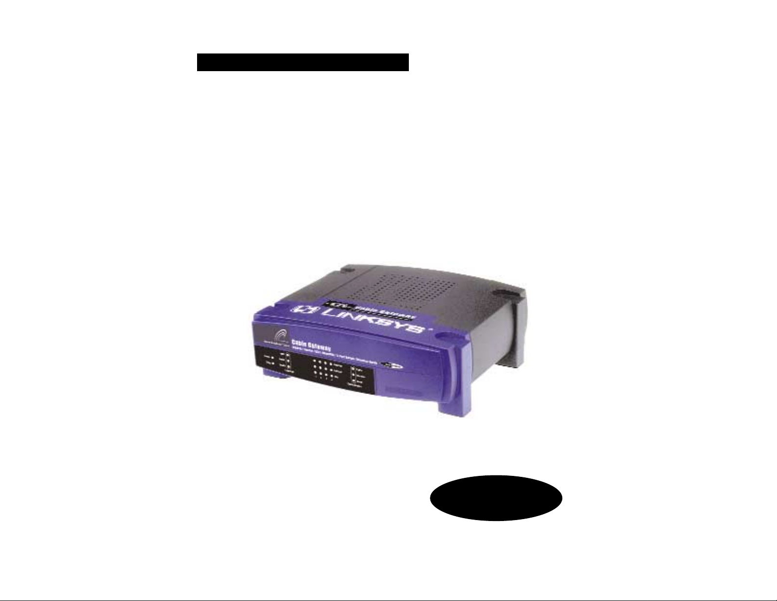
Instant Broadband®Series
Cable Gateway
Modem / Router / USB / Home PNA /
4-Port Switch / Wireless-Ready
Use this guide to install the following product:
BEFCMUH4
User Guide

COPYRIGHT & TRADEMARKS
Copyright © 2002 Linksys, All Rights Reserved. Instant Broadband is a trademark of
Linksys. Linksys is a registered trademark of Linksys. Microsoft, Windows, and the
Windows logo are registered trademarks of Microsoft Corporation. All other trademarks
and brand names are the property of their respective proprietors.
LIMITED WARRANTY
Linksys guarantees that every Instant Broadband™ Cable Gateway Modem / Router /
USB / Home PNA / 4-Port Switch / Wireless-Ready will be free from physical defects in
material and workmanship for one year from the date of purchase, when used within the
limits set forth in the Specifications section of this User Guide. If the product proves
defective during this warranty period, call Linksys Technical Support in order to obtain a
Return Authorization number. BE SURE TO HAVE YOUR PROOF OF PURCHASE ON
HAND WHEN CALLING. When returning a product, mark the Return Authorization number clearly on the outside of the package and include a copy of your original proof of purchase. RETURN REQUESTS CANNOT BE PROCESSED WITHOUT PROOF OF PURCHASE. All customers located outside of the United States of America and Canada shall
be held responsible for shipping and handling charges.
IN NO EVENT SHALL LINKSYS’S LIABILITY EXCEED THE PRICE PAID FOR THE PRODUCT FROM DIRECT, INDIRECT, SPECIAL, INCIDENTAL, OR CONSEQUENTIAL DAMAGES RESULTING FROM THE USE OF THE PRODUCT, ITS ACCOMPANYING SOFTWARE, OR ITS DOCUMENTATION. LINKSYS OFFERS NO REFUNDS FOR ITS PRODUCTS. Linksys makes no warranty or representation, expressed, implied, or statutory,
with respect to its products or the contents or use of this documentation and all accompanying software, and specifically disclaims its quality, performance, merchantability, or
fitness for any particular purpose. Linksys reserves the right to revise or update its products, software, or documentation without obligation to notify any individual or entity.
Please direct all inquiries to:
Linksys P.O. Box 18558, Irvine, CA 92623.
FCC PART 15 CLASS B STATEMENT
In compliance with the Federal Communications Commission (FCC), the following FCC
Part 15 Regulations are provided regarding the installation and operation of the Linksys
BEFCMUH4 Cable Gateway.
This equipment has been tested and found to comply with the limits for a Class B digital
device, pursuant to Part 15 of the FCC Rules. These limits are designed to provide reasonable protection against harmful interference in a residential installation.
This equipment generates, uses and can radiate radio frequency energy and, if not
installed and used in accordance with the instructions, may cause harmful interference
to radio communications. However, there is no guarantee that interference will not occur
in a particular installation. If this equipment does cause harmful interference to radio or
television reception, which can be determined by turning the equipment off and on, the
user is encouraged to try to correct the interference by one or more of the following
measures:
UG-BEFCMUH4-rg-121302NC-BW

Table of Contents
Chapter 1: Introduction 1
The Linksys CableGate w ay 1
Features 1
An Introduction to LANs and WANs 2
IP Addresses 2
Network Setup Overview 4
Chapter 2: Getting to Know the Cable Gateway 5
The Cable Gateway’s Back Panel Ports 5
The Reset Button 6
Rebooting the Cable Gateway 6
The Cable Gateway’s Front Panel LEDs 6
The USB Icon 8
USB Cabling 8
HPNA Cabling 8
Chapter 3: Connecting the Cable Gateway 9
Chapter 4: Configuring the PCs 11
Overview 11
Windows 95, Windows 98, Windows Me 11
Windows 2000 13
Windows XP 15
Chapter 5: Using the Cable Gateway’s
Web-based Utility 17
Assessing the Web-Based Utility 17
The Basic Tabs 18
The Advanced Tabs 21
The Firewall Tabs 30
The Status Tabs 33
The Wireless Tabs 39
Cable Gateway
• Reorient or relocate the receiving antenna.
• Increase the separation between the equipment and the receiver.
• Connect the equipment to an outlet on a circuit different from that to which the r eceiver is connected.
• Consult a dealer or an experienced radio/TV technician for assistance.
This device complies with Part 15 of the FCC Rules. Operation is subject to the following two conditions:
• This device may not cause harmful interference.
• This device must accept any interference received, including interference that may
cause undesired operation.
SAFETY NOTICES
• Caution: To reduce the risk of fire, use only No.26 AWG or larger telecommunication
line cord.
• Do not use this product near water, for example, in a wet basement or near a swimming pool.
• Avoid using this products (other than a cordless type) during an electrical storm.
There may be a remote risk of electric shock from lightning.
Instant Broadband®Series

Instant Broadband®Series
Chapter 1:Introduction
Thank you for choosing the Instant Broadband™ Cable Gatew a y. This Gatew a y allo ws y ou
to set up a network with your PCs and share y our Internet connection.
The Gateway does this by connecting to your Cable line, and using the Gateway’s Ethernet
ports to connect your PCs; it’s like each PC is connected directly to the Internet. This wa y, you
have an Ethernet netw ork where you hav e several PCs utilizing one Internet connection simultaneously . Plus, if y ou add a Linksys wireless PC Card , it can be used as an Access Point and
the Gatewa y can bridge y our Ethernet netw ork with your wireless PCs.
The PCs that you connect to the Gatew a y, when properly configured, create a LAN, or Local
Area Network. They are connected with an Ethernet cable plugged into your computer’s
Ethernet adapter at one end and into one of the Gateway's LAN ports (numbered from one to
four) at the other end. The term “Ethernet” is used to refer to your netw ork accessories, such
as cables and adapters, because Ethernet refers to the type of network that you are setting up.
Ethernet refers to the accessories that transfer computer data from 10Mbps to 100Mbps
(speeds used by network de vices.)
The Gateway allows you to share y our Cable connection using a built-in Cable modem, and
can plug directly into your Cable-enab led wall jack (Cable service line). The PCs that are connected to the Gatewa y share this connection.
• Prevents DoS (Denial of Service) Attacks
• E-mail and Web-based Logging of Security Events
• MAC Address Filtering, Port Forwarding, DMZ Support
• Configurable through Your Networked PC’s Web Browser
• Supports VPN Pass-Through for IPSec, PPTP, and L2TP Protocols
• Internal 4-Port Switch Dramatically Speeds Up Your Network
• DHCP Server Capability to Assign IP Addresses Automatically
• Wireless Capabilities Available with Use of Optional WPC11 (sold separately)
• Supports a High Data Rate of up to 11Mbps for up to 28 Simultaneous
Wireless Connections
• Capable of 64 and 128-Bit WEP Encryption
1
Cable Gateway
Appendix A: Troubleshooting 46
Common Problems and Solutions 46
Frequently Asked Questions 47
Appendix B: Configuring Wireless Security in
Windows XP 51
Appendix C: Installing the TCP/IP Protocol 57
Appendix D: Finding the MAC Address and
IP Address for Your Ethernet Adapter 59
Appendix E: Glossary 63
Appendix F: Specifications 74
Environmental 76
Appendix G: Warranty Information 77
Appendix H: Contact Information 78
The Linksys Cable Gateway
Features
Cable Gateway
Dynamic IP Addresses
A dynamic IP address is automatically assigned to a device on the network,
such as PCs and print servers. These IP addresses are called “dynamic”
because they are only temporarily assigned to the PC or device. After a certain
time period, they expire and may change. If a PC logs onto the network (or the
Internet) and its dynamic IP address has expired, the DHCP server will assign
it a new dynamic IP address.
DHCP (Dynamic Host Configuration Protocol) Servers
DHCP frees you from having to assign IP addresses manuall y e v ery time a ne w
user is added to your network. PCs and other network devices using dynamic
IP addressing are assigned a new IP address by a DHCP server. The PC or net-
work device obtaining an IP address is called the DHCP client. By default, the
Cable Gateway’s WAN setting is DHCP client.
A DHCP server can either be a designated PC on the network or another network device, such as the Cable Gateway. By default, the Cable Gateway acts as
a DHCP server for your local network. If y ou already have a DHCP server running on your network, you must disable that DHCP server or the Cable
Gateway’s DHCP’s feature. If you run more than one DHCP server on your
network, you will experience network errors, such as conflicting IP addresses.
Note: Since the Cable Gateway is a device that connects two networks, it
needs two IP addresses—one for the LAN side, and one for the WAN side.
In this User Guide, you’ll see references to the “WAN IP address” and the
“LAN IP address.”
Since the Cable Gatew a y has firewall security, the only IP address on your
network that can be seen from the Internet is the Cable Gatew a y’s WAN IP
address.
Instant Broadband®Series
32
Simply put, a router is a network device that connects two networks together.
The Cable Gateway has a built-in router that connects your Local Area
Network (LAN), which is the group of PCs in your home or off ice, to the
Wide Area Network (WAN), which is the Internet. The Cable Gateway
processes and regulates the data that travels between these two networks.
Think of the Cable Gateway as a network device with two sides: the first side is
made up of your private Local Area Network (LAN) of PCs. The other, public
side, is the Internet, or the Wide Area Network (WAN), outside of your home or
office.
The Cable Gatew a y’s firewall protects your network of PCs so users on the public, Internet side cannot “see” your PCs. This is how your local network,
remains private. The Cable Gateway protects your network by inspecting the
first packet coming in through the WAN port before delivery to the final destination in the local network. The Cable Gateway inspects Internet port services
like the web server, ftp server, or other Internet applications, and, if allowed,
will forward the packet to the appropriate PC on the LAN side.
What’s an IP Address?
IP stands for Internet Protocol. Every device on an IP-based network, including
PCs, print servers, and routers, requires an IP address to identify its “location,”
or address, on the network. This applies to both the W AN and LAN connections.
There are two ways of assigning an IP address to your network devices.
Static IP Addresses
A static IP address is a fixed IP address that you assign manually to a PC or
other device on the network. Since a static IP address remains valid until you
disable it, static IP addressing ensures that the device assigned it will always
have that same IP address until you change it. Static IP addresses are commonly used with network devices such as ser ver PCs or print servers.
An Introduction to LANs and WANs
IP Addresses
Note: Even if you assign a static IP address to a PC, other PCs can
still use DHCP’s dynamic IP addressing, as long as the static IP
address is not within the DHCP range of the LAN IP Address.
If the Cable Gateway’s DHCP feature fails to provide a dynamic IP
address, refer to “Appendix A: Troubleshooting.”
Cable Gateway
5
Chapter 2:Getting to Know the Cable Gateway
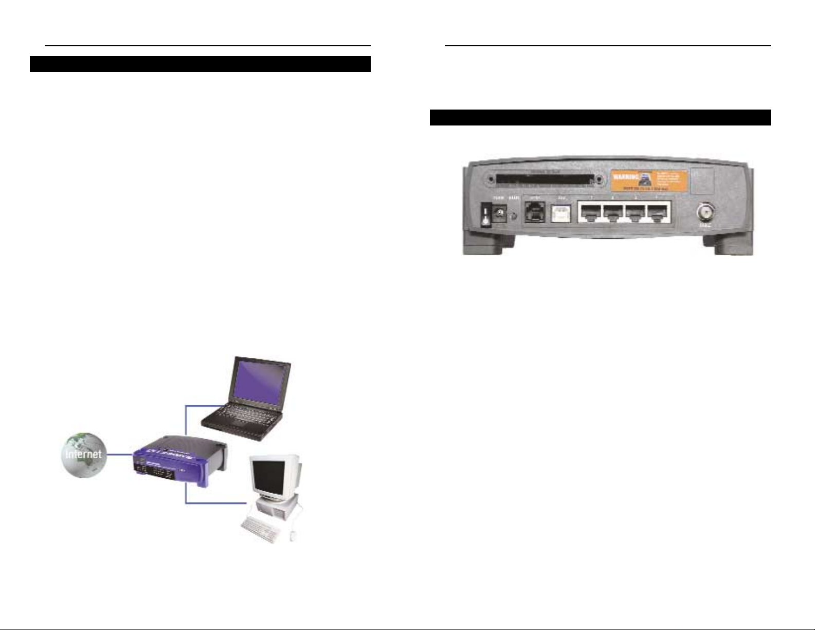
The Cable Gatew ay’s ports are located on the back panel of the Cable Gateway,
as shown in Figure 2-1.
On/Off Switch This switch is used for turning the Cable Gateway
on and off.
Power The Po w er port is where y ou will connect the po w er
adapter.
Reset Press this button to restore the Cable Gateway to it
factory default settings.
Home PNA This is where you can connect your cable for Home
PNA.
USB This is where you can use a USB cable to connect a
PC or other network device to the Cable Gateway.
Ports 1-4 These four ports are used to connect network
devices, such as PCs, print servers, and remote hard
drives to your local area network (LAN).
Cable The Cable port is where you will connect your coax-
ial Cable line.
Wireless PC Card Slot This is where you can connect the optional wireless
PC card (model number WPC11, not included) for
wireless features.
The Cable Gateway’s Back Panel Ports
Figure 2-1
Instant Broadband®Series
This user guide covers the basic steps for setting up a network with the Cable
Gateway. After going through the Chapter 2: Getting to Know the Cable
Gateway, proceed through the following chapters:
• Chapter 3: Connecting the Cable Gateway
This chapter instructs you on how to connect the coaxial Cable line to the
Cable Gateway and connect the PC(s) to the Cable Gateway.
• Chapter 4: Configuring the PCs
This chapter instructs you on how to configure your PC(s) for a DHCP connection, if the network settings are not already set to DHCP.
• Chapter 5: Using the Cable Gateway’s Web-based Utility
This chapter explains how to configure the Cable Gateway for wireless networking using your web browser and the Cable Gateway’s web-based utility.
When you’re f inished with the basic steps, you are ready to connect to the
Internet through your new network. An example of such a network is shown in
Figure 1-1.
4
Network Setup Overview
Notebook with
Ethernet Adapter
Cable Gateway
with Modem / Router / USB / Home
PNA / 4-Port Switch / Wireless-Ready
LAN
PC with
Ethernet Adapter
WAN
Figure 1-1
Cable Gateway
Instant Broadband®Series
76
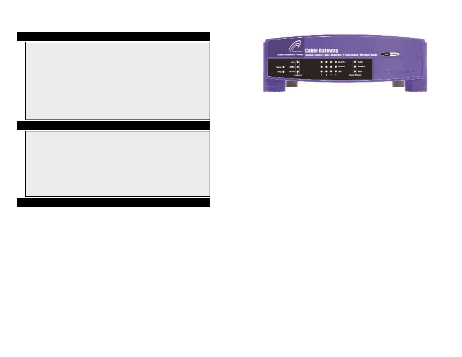
Link/Act Green. The Link/Act LED serves two purposes. If
the LED is solid, the Cable Gateway is successfully
connected to a device through the corresponding port
(1, 2, 3, or 4). If the LED is flashing, the Cable
Gatewa y is acti vel y sending or recei ving data o v er that
port.
Full/Col Green. The Full/Col LED serves tw o purposes. If this
LED is solid, the connection made through the corresponding port (1, 2, 3 or 4) is running in Full Duplex
mode, otherwise it is operating in Half Duplex mode.
If the LED flashes, the connection is experiencing collisions. Occasional collisions are normal.
100 Green. This LED is solid w hen a successful 100Mbps
connection is made through the corresponding port (1,
2, 3 or 4). If this LED does not light up, then the connection speed on that port is 10Mbps.
Cable Modem - Cable Green. This LED will go through a series of flashes
as the Cable Gatew a y goes through its startup and registration process. It will remain solid when registration is complete and the Cable Gatew a y is operational.
Cable Modem - Receive Green. This LED flashes when data is being received
through the cable Gateway interface.
Cable Modem - Send Green. This LED flashes when data is being trans-
mitted through the Cable Gateway Interface.
Proceed to “Chapter 3:Connecting the Cable Gateway.”
Power Green. The Power LED is solid when the Cable Gateway is
powered on.
Diag Red. If the Diag LED is solid or flashes after the startup
process, the Cable Gateway may be malfunctioning. See
"Appendix A: Troubleshooting" if you encounter this problem.
Link/Act USB Green. This LED is solid w hen a PC is connected to the Cable
Gateway via USB, and drivers are installed.
Link/Act HPNA Green. This LED is solid when the Cable Gateway is con-
nected to another HPNA device or an HPNA network.
Link/Act WLANGreen. This LED is solid when a wireless PC Card (model
number WPC11, not included) is installed and functioning in
the Cable Gateway. The LED flashes during wireless activity.
The Cable Gateway’s Front Panel LEDs
Figure 2-2
Briefly pressing the Reset Button, along with rebooting the Cable Gateway,
will refresh the Cable Gateway’s connections. If the Cable Gateway locks up,
simply press the Reset Button or power it down for three to f ive seconds.
Pressing the Reset Button and holding it in for a few seconds will clear all of
the Cable Gateway’s data and restore the factory defaults. This should be done
only if you are experiencing networking problems and have exhausted all of
the other troubleshooting options. By resetting the Cable Gateway, you run the
risk of creating conflicts between your PCs’actual IP Addresses and what the
Cable Gateway thinks the IP Addresses of the PCs should be. You may be
forced to reboot each network PC.
The Reset Button
You should only reboot the Cable Gateway after all other troubleshooting
methods have been exhausted but before calling Linksys Technical Support.
There are three ways to reboot the Cable Gateway:
1) Briefly press the Reset Button.
2) Turn the Cable Gateway’s power off for a few seconds and power it back on
again.
3) Unplug the Cable Gateway’s power adapter and plug it back in again.
Rebooting the Cable Gateway may cause conflicts with IP Addresses.
Rebooting the Cable Gateway
9
Cable Gateway
Chapter 3:Connecting the Cable Gateway
You will connect the Cable Gateway to your Cable service’s coaxial cable line
and to the computers in your home or business.
First, make sure that all the devices that you’ll be working with are powered
down, including your PCs and the Cable Gateway.
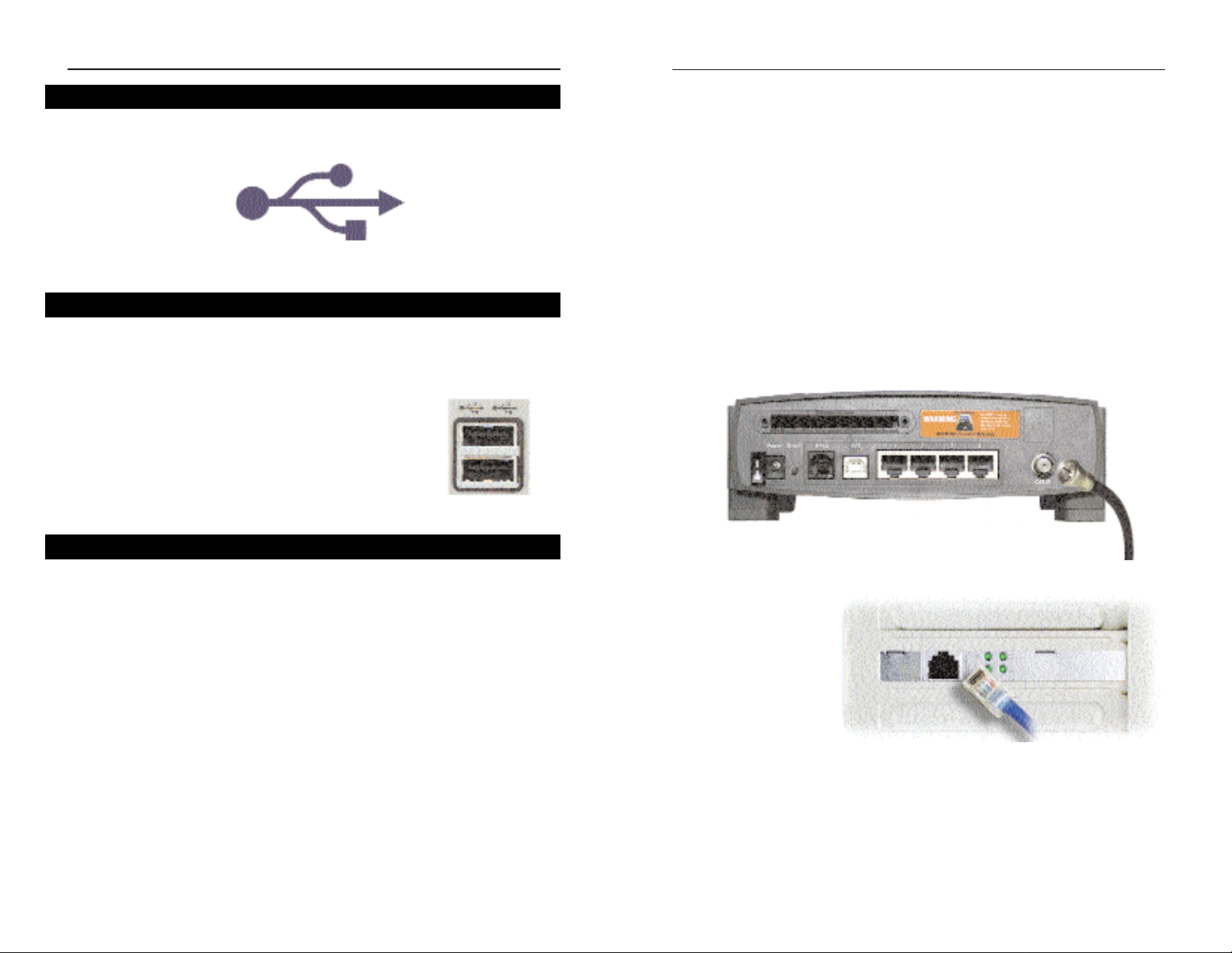
1. Connect the coaxial cable that is provided by your cable service provider to
the Cable port that is on the back of the Cable Gateway, as shown in Figure
3-1.
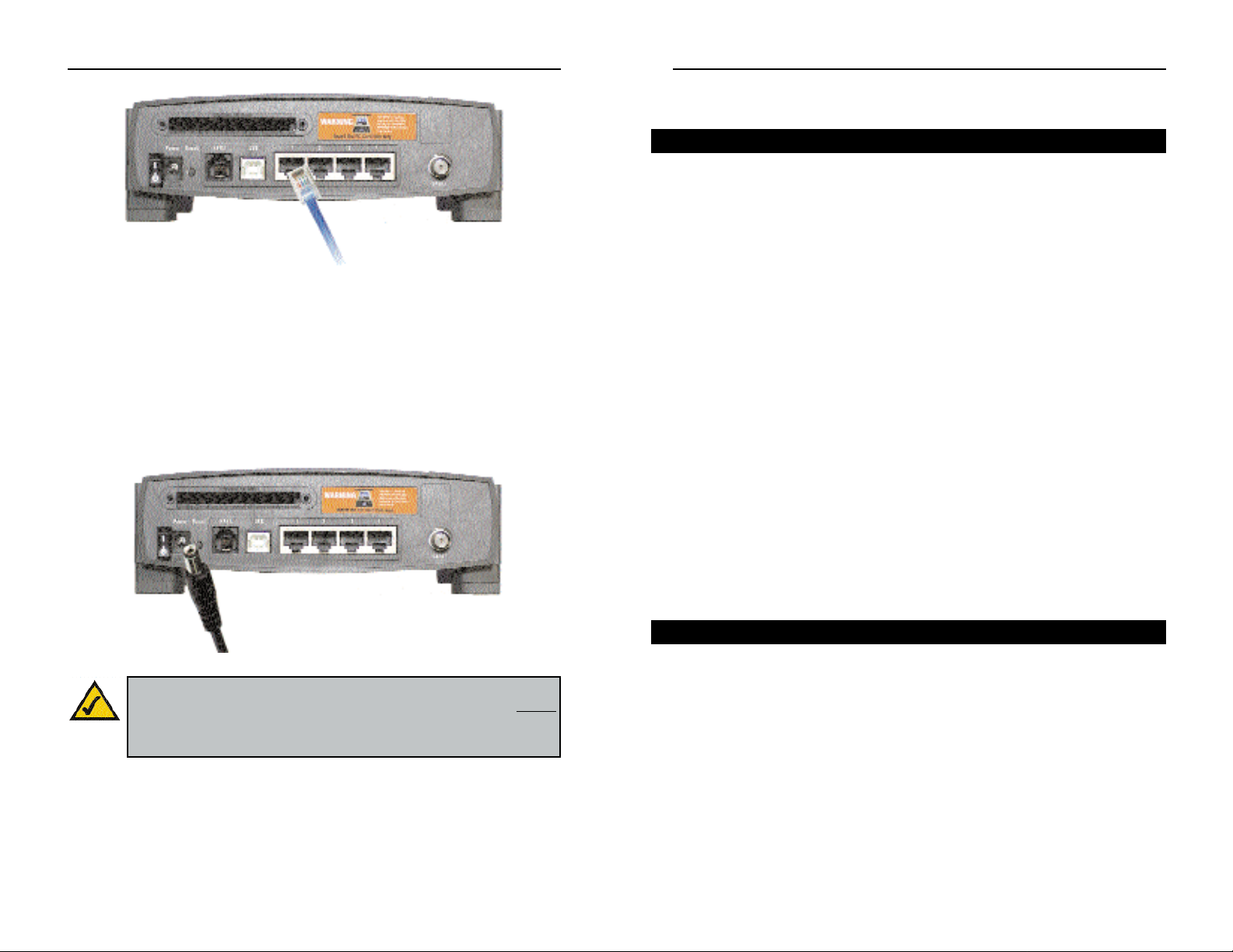
2. Connect one end of
an Ethernet cable to
your PC’s Ethernet
adapter, as shown in
Figure 3-2.
Note: If your PC’s Ethernet adapter is not set up, please refer to the Ethernet
adapter’s user guide for more information.
3. Connect the other end of the cable to one of the LAN ports on the back of the
Cable Gateway, as shown in Figure 3-3.
Figure 3-1
Figure 3-2
Instant Broadband®Series
The USB icon, shown in Figure 2-3, marks a USB port on a PC or device.
The Cable Gateway comes with one USB cable. Connect one end of the USB
cable to the Cable Gateway. Connect the other end to a computer’s USB port.
The picture shows tw o USB ports as they might appear on
your computer. Note the two USB icons marking the
ports.
Due to the limitations of standard telephone cables, HPNA devices require that
HPNA cabling does not exceed a total length of 150 meters (500 feet). In other
words, if you have more than 500 feet of telephone wires connecting your
HPNA device to your network, you will be more likely to experience data loss.
Any standard telephone cable can be used to connect the Cable Gate w a y to your
HPNA network.
8
The USB Icon
Figure 2-3
USB Cabling
Figure 5-2
HPNA Cabling
Cable Gateway
Chapter 4: Configuring the PCs
The instructions in this chapter will help you configure each of your computers to be able to communicate with the Cable Gateway.
T o do this, you need to configure your PC’s network settings to obtain an IP (or
TCP/IP) address automatically (called DHCP). Computers use IP addresses to
communicate with each other across a local network or the Internet.
You will need to know which operating system your computer is running, such
as W indo ws 95, 98, Me, 2000, or XP. One w ay to find out which operating system you have is by clicking the Start button and selecting the Settings option.
Then, open the Control Panel, and double-click the System icon. The screen
that appears should display your operating system.
You may need to configure each computer you are connecting to the Cable
Gateway.
The next few pages show you, step by step, ho w to configure your network settings based on the type of Windows operating system you are using.
If your operating system is not referenced here, refer to your operating system’s
documentation.
Once you've configured your computers, continue to “Chapter 5: Using the
Cable Gateway’s Web-based Utility.”
1. Go to the Network screen. Do this by clicking the Start button, selecting
Settings and opening the Control Panel. From there, double-click the
Network icon.
11
Instant Broadband®Series
10
Overview
Make sure there is an Ethernet cable connected from the Cable Gatew a y to e v ery
PC that you want on your local network. If you are connecting more than four
PCs to the Cable Gatew ay via the Ethernet, you will also need to connect a hub
or switch to the Cable Gateway.
4. Connect the power adapter to the Cable Gateway, as shown in Figure 3-4.
Plug the other end of the power adapter into the electrical outlet, preferably
a surge protector.
5. Turn on the Cable Gateway. Then, turn on the first PC that you want to use
to configure the Cable Gateway.
Go to “Chapter 4: Configuring the PCs.”
Figure 3-3
Note: If you hav e a Linksys wireless PC Card, be sure to fully insert
it into the PC Card slot on the back of the Cable Gateway before
turning on the power. You must have this card inserted in order to
use the Cable Gateway's wireless features.
Figure 3-4
Windows 95, 98, and Me
Cable Gateway
4. Now click the Gateway tab to ensure that the Installed Gateway field is left
blank. Click the OK button.
5. Click the OK button again. Windows may ask you for the original
Windows installation disk or additional f iles. Supply them by pointing to
the correct file location, e.g., D:\win98, D:\win9x,
c:\windows\options\cabs, etc. (if “D” is the letter of your CD-ROM drive).
6. Windows may ask y ou to restart your PC. Click the Yes button. If W indows
does not ask you to restart, restart your computer anyway.
Go to “Chapter 5: Using the Cable Gateway’s Web-based Utility.”
1. Go to the Network screen by clicking the Start button. Click Settings and
then Control Panel. From there, double-click the Network and Dial-up
Connections icon.
2. Select the Local Area Connection icon for the applicable Ethernet adapter
(usually it is the first Local Area Connection listed). Do not choose a
TCP/IP entry whose name mentions DUN, PPPoE, VPN, or AOL. Doubleclick the Local Area Connection.
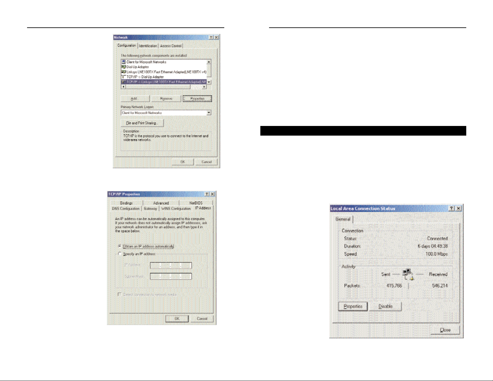
3. The Local Area
Connection
Status screen will
appear, as shown
in Figure 4-3.
Click the
Properties button.
13
Instant Broadband®Series
2. On the Configuration tab,
select the TCP/IP line for
the applicable Ethernet
adapter, as shown in Figure
4-1. Do not choose a
TCP/IP entry whose name
mentions DUN, PPPoE,
VPN, or AOL. If the word
TCP/IP appears by itself,
select that line. (If there is
no TCP/IP line listed, refer
to “Appendix C: Installing
the TCP/IP Protocol” or
your Ethernet adapter’s
documentation to install
TCP/IP now.) Click the
Properties button.
3. Click the IP Address
tab. Select Obtain an
IP address automatically, as shown in
Figure 4-2.
12
Figure 4-2
Figure 4-1
Windows 2000
Figure 4-3
The following instructions assume you are running Windows XP with the
default interface. If you are using the Classic interface (where the icons and
menus look like previous Windows versions), please follow the instructions for
Windows 2000.
1. Open the Network screen. To do this, click the Start button and select the
Control Panel. From there, click the Network and Internet Connections
icon, followed by the Network Connections icon.
2. Select the Local Area Connection icon for the applicable Ethernet adapter
(usually it is the first Local Area Connection listed). Double-click the
Local Area Connection and click the Properties button.
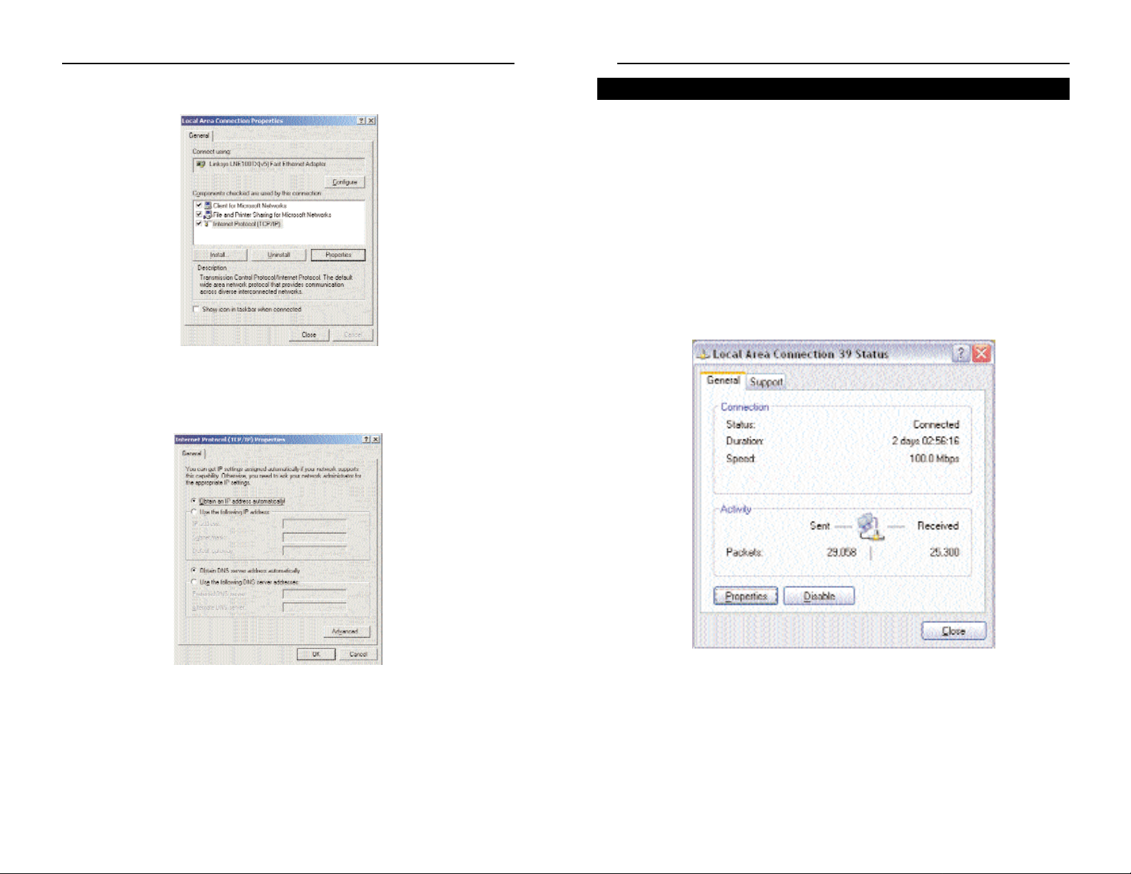
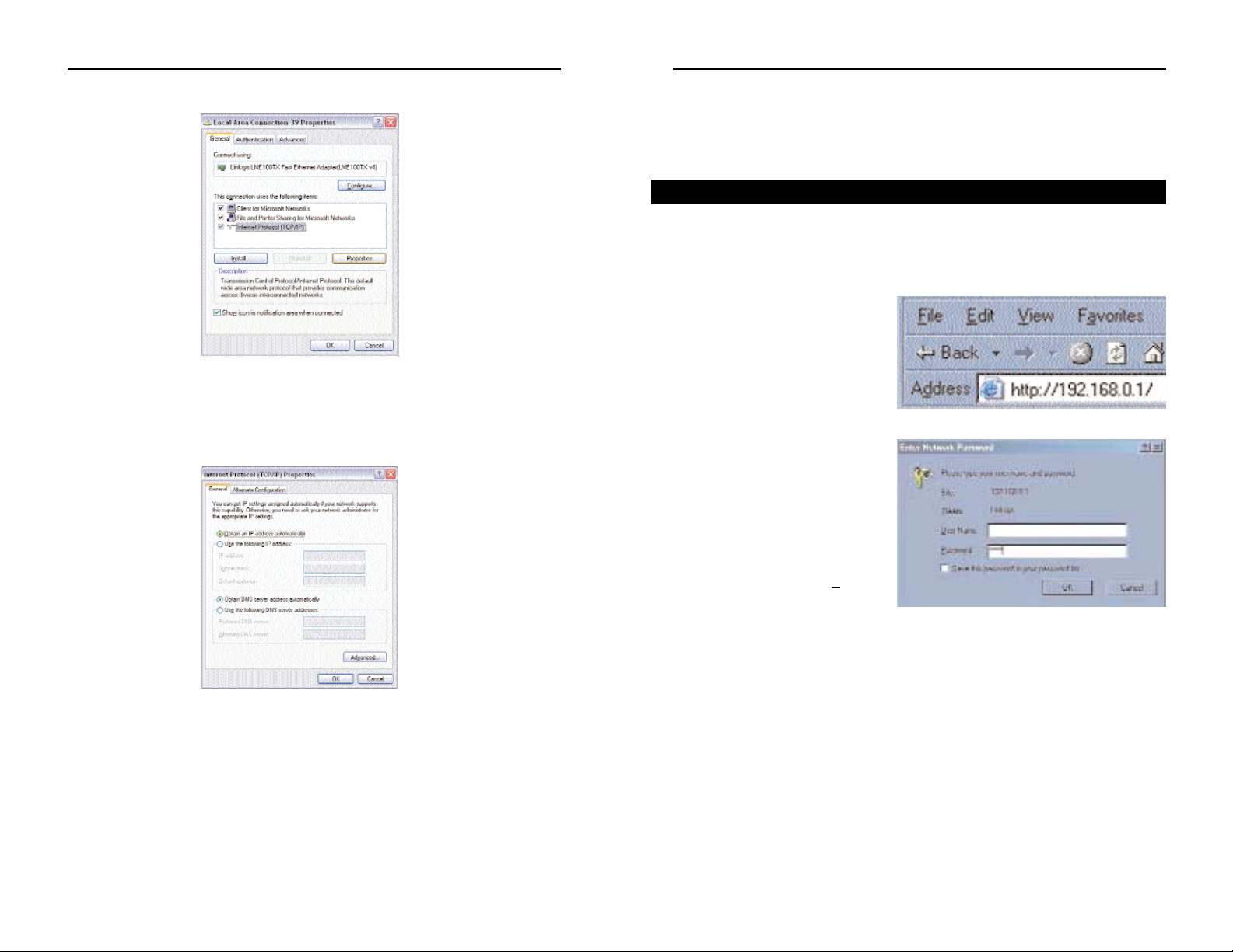
3. The Local Area Connection Status screen will appear. Click the Properties
button.
15
Instant Broadband®Series
4. Select Internet Protocol (TCP/IP), as shown in Figure 4-4, and click the
Properties button.
5. Select Obtain
an IP address automatically, as shown in Figure 4-5. Once the new win-
dow appears, click the OK button. Click the OK button again to complete
the PC configuration.
6. Restart your computer.
Go to “Chapter 5: Using the Cable Gateway’s Web-based Utility.”
14
Cable Gateway
Windows XP
Figure 4-6
Figure 4-4
Figure 4-5
Chapter 5:Using theCable Gateway’s Web-based Utility
For your convenience, an administrative utility has been programmed into the
Cable Gateway. From this browser-based utility, you can view the Cable
Gateway’s current status and, when wireless functions are enabled, administer
the wireless settings. This chapter explains all of the functions in this utility.
1. Open your web browser, and
enter 192.168.0.1 into the web
browser’s Address field, as
shown in Figure 5-1. Then,
press the Enter key.
2. An Enter Network Password
window, similar to that shown
in Figure 5-2, appears. Leave
the User Name field empty,
and enter admin (the default
password) in lowercase letters
in the Password field. Then,
click the OK button. Don’t
check the box next to S
av e this
password in your password
list, because you should
change the password for better
network security.
The Utility screen will be displayed next in your browser. Located on the left
of your screen, you have five choices to navigate through the utility: Basic,
Advanced, Firewall, Status, and Wireless. When you click on any of these, you
will have a choice of tabs at the top of the screen. When you click Basic, you
have a choice of Setup and DHCP. When you click Advanced, you have a
choice of Options, IP Filtering, MAC F iltering, Port F iltering, Forwarding, Port
Triggers, DMZ Host. When you click Firewall, you have a choice of W e b
Filter and Event Log. When you click Status, you have a choice of Software,
Connection, Security, and Diagnostics. When you click Wireless, you
have a choice of Basic, Privacy, and Advanced.
17
Instant Broadband®Series
4. Select Internet Protocol (TCP/IP), and click the Properties button.
5. Select Obtain an IP address automatically. Once the new window
appears, click the OK button. Click the OK button again (or the Close but-
ton if any settings were changed) to complete the PC configuration.
6. Restart your computer.
Go to “Chapter 5: Using the Cable Gateway’s Web-based Utility”.
16
Cable Gateway
Accessing the Web-Based Utility
Figure 4-7
Figure 4-8
Figure 5-2
Figure 5-1
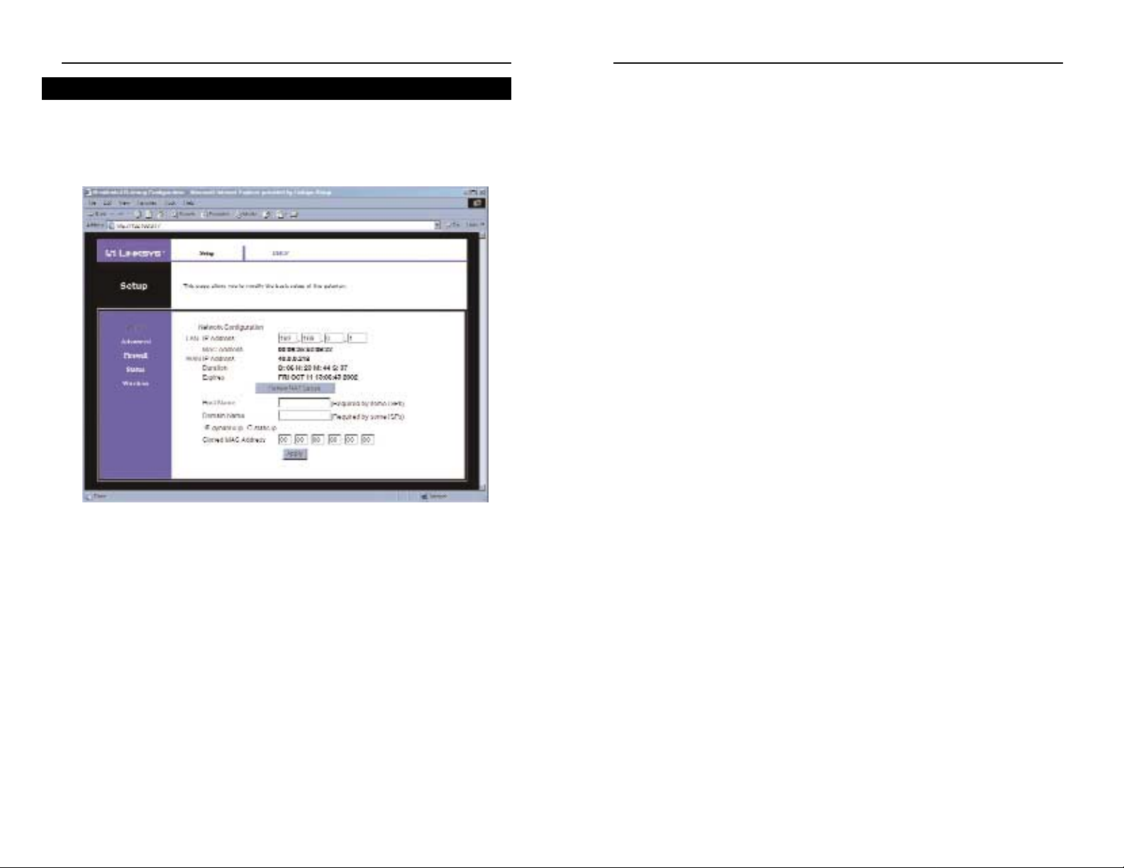
Duration The length of the DHCP lease for the IP
assigned by your Cable Provider.
Expires The date and time that the DHCP lease
expires. After this time, your Cable Provider
may assign a different IP address to your
Cable Gateway.
Renew NAT Lease Click the Renew NAT Lease button to manu-
ally renew the DHCP lease of the IP address
assigned by the Cable Provider.
Host Name If your ISP requires a host name, enter it in
this field.
Domain Name If your ISP requires a domain name, enter it in
this field.
Dynamic IP/Static IP Click the button next to the type of IP Address
that your ISP uses.
Cloned MAC Address The Router’s MAC address is a 12-digit code
assigned to a unique piece of hardware for
identification, like a social security number.
Enter the 12 digits of your adapter’s MAC
address in the fields. This clones your network adapter’s MAC address onto the Router,
so you do NOT have to call your ISP to
change the registered MAC address to the
Router’s MAC address.
When finished making your changes on this tab, click the Apply button
Click the Apply button to save any changes.
19
Instant Broadband®Series
The Setup Tab
This screen allows you to change the setup of the Cable Gateway.
Network Configuration
LAN IP Address The values for the Cable Gateway’s IP address are
shown here. The def ault value is 192.168.0.1.
MAC Addr ess This is the Cable Gateway’s MAC address. This is
the address that will be registered with your Cable
Provider to enable Internet access.
WAN IP Address The values for the Cable Gateway’s IP address
that are seen by external users on the Internet.
This IP address is assigned by your Cable
Provider.
18
Cable Gateway
The Basic Tabs
Figure 5-3
 Loading...