

Page 1

Specifications are subject to change without notice.
MediaTek LinkIt™ Smart 7688
User Manual
Version: 0.9 Beta
Release date: October 2015
Unauthorized reproduction of this information in whole or in part is strictly prohibited.
This document contains information that is proprietary to MediaTek Inc.
© 2015, 2016 MediaTek Inc.
Page 2

Revision
Date
Description
0.9
October 2015
Close Beta
MediaTek LinkIt™ Smart 7688 User Manual
Document Revision History
© 2015, 2016 MediaTek Inc.
Page 1 of 38
This document contains information that is proprietary to MediaTek Inc.
Unauthorized reproduction or disclosure of this information in whole or in part is strictly prohibited.
Page 3
MT7688AN SOC Specifications
CPU
MIPS24KEc (580 MHz)
Total DMIPs
580 x 1.6 DMIPs
I-Cache, D-Cache
64 KB, 32 KB
L2 Cache
N/A
• DDR1/DDR2
• Max. 2 Gb, 193 MHz
• 3B addr mode (max
512Mbit)
SD
SD-XC (class 10)
RF
1T1R 802.11n 2.4GHz
Package
DR-QFN156-12 mm x 12 mm
MediaTek LinkIt™ Smart 7688 User Manual
1. Introduction
LinkIt Smart 7688 development platform is an IoT development platform by
MediaTek Labs. It enables you to design and create Wi-Fi connected devices
for the home, the office and Cloud applications.
1.1. What is MediaTek LinkIt Smart 7688 Development
Platform
The LinkIt Smart 7688 is an open development platform based on Linux
distribution OpenWrt
hardware configurations: LinkIt Smart 7688 (MPU only) and LinkIt Smart 7688
Duo (MPU and MCU). The LinkIt Smart 7688 is powered by MediaTek’s MT7688
SOC and supports Windows, Mac OS X and Linux.
LinkIt Smart 7688 Duo has the same MPU in addition to a MCU which is
powered by ATmega32U4. It supports Arduino and high level programming
language such as Python, Node.js and C so that you can create your own
scripts for rich peripheral interactions.
. It offers two development boards which come in two
The LinkIt Smart 7688 development platform supports built-in Wi-Fi,
Ethernet, USB host and Micro-SD card slot as well as serial port for Linux
console.
1.2. MediaTek MT7688AN Chip Specification Summary
Specifications of the MT7688AN SOC are shown in below.
Memory
SPI Flash
• 16 bits
128Mbit)
• 4B addr mode (max
PCIe 1
USB 2.0 1
Unauthorized reproduction or disclosure of this information in whole or in part is strictly prohibited.
Interface Count
© 2015, 2016 MediaTek Inc.
This document contains information that is proprietary to MediaTek Inc.
Page 2 of 38
Page 4
Interface Count
Fast Ethernet Switch 5
I2S 1
PCM 1
PWM 4
SPI 1
I2C 1
UART(Lite) 3
JTAG 1
Table 1 MT7688AN SOC Specification
1.3. LinkIt Smart 7688
MediaTek LinkIt™ Smart 7688 User Manual
LinkIt Smart 7688 is one of the most highly integrated and compact hardware
development boards available for IoT prototyping.
1.3.1. Key Features
LinkIt Smart 7688’s key features include the following:
• Wi-Fi 802.11 b/g/n (2.4G)
• Pin-out for GPIO, I2C, I2S, SPI, UART, PWM and Ethernet Port
• 580 MHz MIPS CPU
• 32MB flash and 128MB DDR2 RAM
• USB host
• Micro SD slot
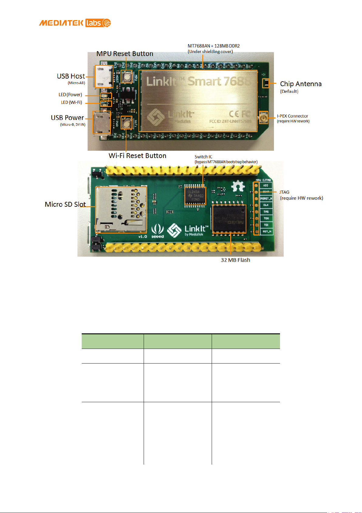
LinkIt Smart 7688 is shown in Figure 1.
© 2015, 2016 MediaTek Inc.
This document contains information that is proprietary to MediaTek Inc.
Unauthorized reproduction or disclosure of this information in whole or in part is strictly prohibited.
Page 3 of 38
Page 5
data will be
MediaTek LinkIt™ Smart 7688 User Manual
Figure 1 LinkIt Smart 7688 development board (MPU only)
1.3.2. Buttons
The buttons description on LinkIt Smart 7688 and how to use them are
described in Table 2.
Scenario Button Action
Resets the MPU MPU Reset Button One Press
Resets Wi-Fi to
AP mode
Factory resets
and enters AP
mode
WARNING:
Restore to
default setting
and all user
Wi-Fi Reset
Button
(After system is
boot up)
Wi-Fi Reset
Button
(After system is
boot up)
Press for at
least 5 seconds
and release
Press for at
least 20 seconds
and release
© 2015, 2016 MediaTek Inc.
Page 4 of 38
This document contains information that is proprietary to MediaTek Inc.
Unauthorized reproduction or disclosure of this information in whole or in part is strictly prohibited.
Page 6
removed from
Mode
Status
LED blink pattern
3 blinks in 1 second
Without client
Disconnected
Off
Connecting
2 blinks in 1 second
Blinking based on
Scenario Button Action
the device
MediaTek LinkIt™ Smart 7688 User Manual
Upgrades
firmware from a
USB drive
Upgrades boot
loader from a
USB drive
WARNING:
Restore to
default setting
and all user
data will be
removed from
the device
Table 2LinkIt Smart 7688 Development board buttons
Wi-Fi Reset
Button (At power
up)
Wi-Fi Reset
Button (At power
up)
Press for at
least 5 seconds
and release
Press for at
least 20 seconds
and release
1.3.3. LEDs
• Power
Power LED turns solid on in green color when power is supplied.
• Wi-Fi
Wi-Fi LED are in orange color and their blink pattern is described in Table
3.For more information on Access Point and Station mode, please see 2.3,
“Network Environment”.
With client
device
AP Mode
device
Station
Mode
Data
transmission
Table 3 Wi-Fi LED blink pattern in LinkIt Smart 7688 HDK
and pause for 0.5
seconds (cycle
repeats)
Off
the transmitted data
package
Unauthorized reproduction or disclosure of this information in whole or in part is strictly prohibited.
© 2015, 2016 MediaTek Inc.
This document contains information that is proprietary to MediaTek Inc.
Page 5 of 38
Page 7

Approximate Power
Peak
475.3 mA
Average
255.6 mA
Device boot up
Peak
605.4 mA
MediaTek LinkIt™ Smart 7688 User Manual
1.3.4. Antenna
There are two types of antenna support available on LinkIt Smart 7688
development board:
1) Built in Wi-Fi chip antenna and it is the default antenna.
2) I-PEX connector for external antenna.
To enable the connector, you’ll need to remove the resistor R233 located on
the top left corner of the I-PEX connector, as circled in Figure 2.
Figure 2 Removing the resistor to enable I-PEX connector
1.3.5. USB Host
LinkIt Smart 7688 provides USB host capability which enables it to connect
to different USB devices such as webcams, USB drives, keyboards, joysticks
and more. The connector used is USB Micro-AB type.
1.3.6. USB Power
The USB cable provides 5V steady power source to LinkIt Smart 7688
development boards. When you add peripheral devices such as SD card, USB
drive or other USB devices to the development board, additional power may
be consumed. Please use a proper USB cable to reduce power loss. If your
peripheral device consumes power heavily, it’s better to use an external
power source for it.
The approximate power consumption of various devices used on LinkIt Smart
7688 is described in below.
Scenario
Consumption
To establish WiFi connection
© 2015, 2016 MediaTek Inc.
This document contains information that is proprietary to MediaTek Inc.
Unauthorized reproduction or disclosure of this information in whole or in part is strictly prohibited.
Page 6 of 38
Page 8

Approximate Power
Average
195.1 mA
Downloading file
Peak
540.4 mA
Average
275.8 mA
Downloading a
Peak
569.5 mA
Average
304.9 mA
Downloading a
Peak
522.4 mA
Average
271.3 mA
MediaTek LinkIt™ Smart 7688 User Manual
Scenario
Consumption
to a SD Card via
Wi-Fi
file to a USB
Drive via Wi-Fi
file to flash
via Wi-Fi
Table 4 Peripherals Power Consumption
1.3.7. Accessories
LinkIt Smart 7688’s standard package comes with the development board only.
You will need additional accessories for different purposes as described
below.
1) USB Power Cable (Required): You’ll need a USB type A to
Micro-B plug cable to power the LinkIt Smart 7688
development board from a PC or other USB powered source.
2) Micro USB OTG (On-The-Go) or Host Cable (Optional): Use this
OTG cable to access Type A USB devices such as USB drive or
USB camera and more as shown in Figure 3.
Figure 3 USB OTG cable
3) USB-UART Cable (Optional): Use this cable to communicate to
Linux console.
4) Micro SD Card (Optional): Use Micro SD card for extra
storage space for applications and data.
5) USB Drive (Optional): For extra storage. You can also use it
to store bootloader and firmware to upgrade LinkIt Smart
7688.
Unauthorized reproduction or disclosure of this information in whole or in part is strictly prohibited.
© 2015, 2016 MediaTek Inc.
This document contains information that is proprietary to MediaTek Inc.
Page 7 of 38
Page 9
MediaTek LinkIt™ Smart 7688 User Manual
1.3.8. Breakout Board (TBD)
1.3.9. JTAG
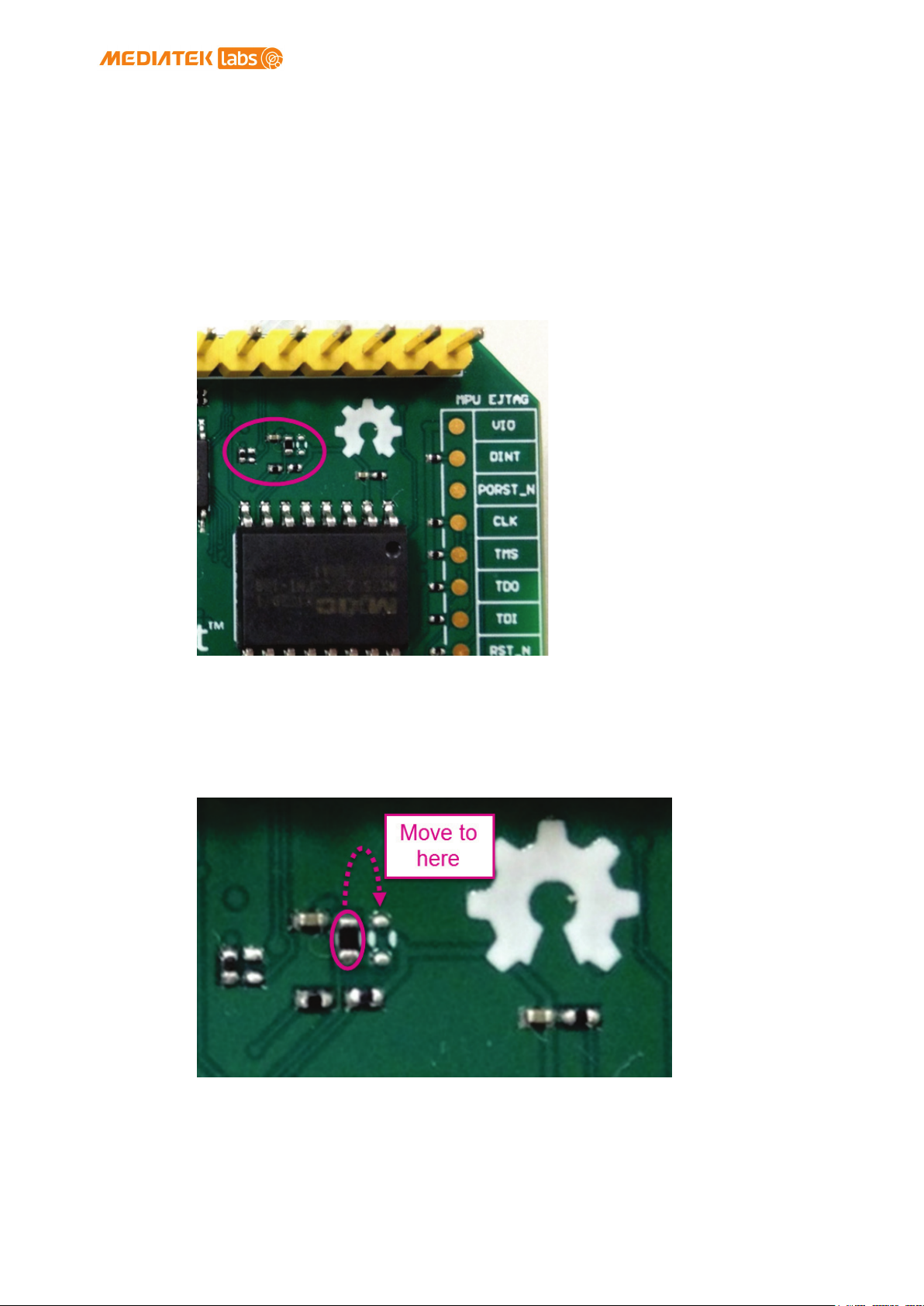
You can use JTAG interface to debug MT7688AN. To access JTAG interface, you
will need to unsolder resistor R95 and solder it to resistor R3 on the
7688 development board. After you’ve moved the resistor and reboot the
device you’ll activate JTAG function. The steps are:
1) Find a group of resistors on the bottom side of LinkIt Smart
7688 (top-right view) as circled in below.
Figure 4 JTAG resistors on LinkIt Smart 7688 Bottom view
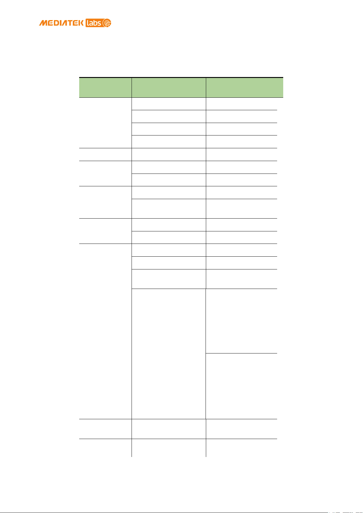
2) Next, you will move a resistor by unsoldering and soldering
it to a lower position as shown in below, after you’ve
finished moving the resistor, restart the device and you
should be able to activate JTAG function.
Figure 5 Moving a resistor to access JTAG mode
© 2015, 2016 MediaTek Inc.
This document contains information that is proprietary to MediaTek Inc.
Unauthorized reproduction or disclosure of this information in whole or in part is strictly prohibited.
Page 8 of 38
Page 10
LinkIt Smart 7688
Chipset
MT7688AN
Core
MIPS24KEc
Clock speed
580MHz
Working voltage
3.3V
PCB Size
Dimensions
55.7 x 26 mm
Flash
32MB
RAM
128MB DDR2
USB Power
5V (USB Micro-B)
3.3V (Pin
Pin Count
22 (MT7688AN)
Voltage
3.3v
Pin Count
4 (MT7688AN)
Voltage
3.3v
7 bits
External
MediaTek LinkIt™ Smart 7688 User Manual
1.3.10. Specifications
The key specifications of LinkIt Smart 7688 development boards are shown
inTable 5.
Category Feature
MPU
Memory
Power Source
VCC
GPIO
Spec.
Breakout)
PWM
Interrupts
SPI
Max. Resolution
(customizable)
100kHz@1-bit
50kHz@2-bit
25kHz@3-bit
12.5kHz@4-bit
6.25kHz@5-bit
3.125kHz@6-bit
1.5625kHz@7-bit
Maximum
(Standard mode)
Frequency@Resoluti
on
40MHz@1-bit
20MHz@2-bit
10MHz@3-bit
5MHz@4-bit
2.5MHz@5-bit
1.25Mhz@6-bit
625kHz@7-bit
(Fast mode)
Pin Count 22 (MT7688AN)
Set count 1 (MT7688AN)
Unauthorized reproduction or disclosure of this information in whole or in part is strictly prohibited.
© 2015, 2016 MediaTek Inc.
This document contains information that is proprietary to MediaTek Inc.
Page 9 of 38
Page 11

LinkIt Smart 7688
• P22, P23,P24
Max. Speed
25 MHz
P28, P29, P30,
Max. Speed
25 MHz
Set Count
1 (MT7688AN)
P10, P11, P12,
Set Count
1
Pin numbers
P20, P21
Speed
120K/400K
Pin Count
1 (MT7688AN)
Pin numbers
P6, P7
Connector type
Micro-AB
1T1R 802.11 b/g/n
1-port 10/100 FE
Pin numbers
P2, P3, P4, P5
Micro SD
MediaTek LinkIt™ Smart 7688 User Manual
Category Feature
Pin numbers
Set count 1 (MT7688AN)
SPI Slave
Pin numbers
I2S
Pin numbers
I2C
Spec.
(Shared with
on-board
flash)
• P25
P31
P13
Set Count
UART (Lite)
Pin numbers
Max. Speed 115,200 bps
USB Host
Wi-Fi
Communicatio
n
Ethernet
User Storage SD Card
3 (MT7688AN)
P8, P9, P16, P17,
P18, P19
(2.4G)
PHY
SDXC
Unauthorized reproduction or disclosure of this information in whole or in part is strictly prohibited.
Table 5 LinkIt Smart 7688 development boards specifications
© 2015, 2016 MediaTek Inc.
This document contains information that is proprietary to MediaTek Inc.
Page 10 of 38
Page 12

MediaTek LinkIt™ Smart 7688 User Manual
1.3.11. Pin-out Diagram
This pin-out diagram helps you to map the pins on LinkIt Smart 7688
development board to the peripheral devices you want to attach through
interfaces such as GPIO, PWM, I2C, I2S, SPI, UART and more. The available
pins for LinkIt Smart 7688 HDK are illustrated in the next page. You can
also download it from MediaTek Labs website.
© 2015, 2016 MediaTek Inc.
Page 11 of 38
This document contains information that is proprietary to MediaTek Inc.
Unauthorized reproduction or disclosure of this information in whole or in part is strictly prohibited.
Page 13
MediaTek LinkIt™ Smart 7688 User Manual
1.4. LinkIt Smart 7688 Duo
LinkIt Smart 7688 Duo is powered by the same MT7688AN SOC as LinkIt Smart
7688, but adds an extra ATMega32U4 on the development board. This supports
additional features including Analog I/O support and Arduino IDE support.
The board’s functionality thus becomes a combination of both chipsets: WiFi and Ethernet support through OpenWRT Linux on MT7688AN SOC, and various
kinds of peripheral support through Arduino on ATMega32U4 microcontroller.
1.4.1. Key Features
Linkit Smart 7688 Duo’s key features include the following:
• Wi-Fi 1T1R 802.11 b/g/n (2.4G)
• Pin-out for GPIO, I2C, I2S, SPI, SPIS, UART, PWM and Ethernet Port
• 580 MHz MIPS CPU
• 32MB flash and 128MB DDR2 RAM
• Built-in USB host and Micro SD slot
• Arduino support (ATmega32U4)
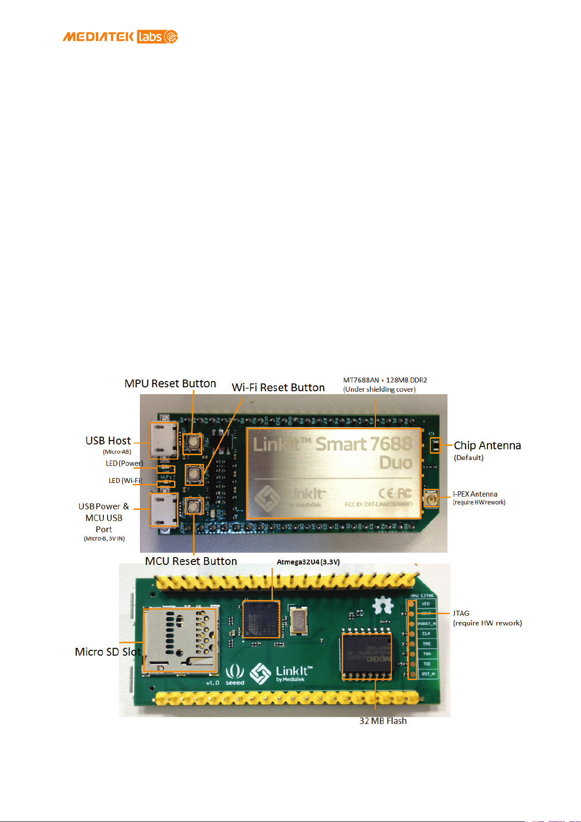
LinkIt Smart 7688 Duo is shown in Figure 6.
Figure 6 LinkIt Smart 7688 Duo development board (MPU + MCU)
© 2015, 2016 MediaTek Inc.
This document contains information that is proprietary to MediaTek Inc.
Unauthorized reproduction or disclosure of this information in whole or in part is strictly prohibited.
Page 12 of 38
Page 14

MediaTek LinkIt™ Smart 7688 User Manual
1.4.2. Buttons
The buttons description on LinkIt Smart 7688 Duo and how to use them are
described in Table 7.
Scenario Button Action
Resets the MPU MPU Reset Button One Press
Resets the MCU
Enters MCU boot
loader mode
(Timeout after
8 seconds)
Resets Wi-Fi to
AP mode
Factory resets
and enters AP
mode
WARNING:
Restore to
default setting
and all user
data will be
removed from
the device
Upgrades
firmware from a
USB drive
MCU Reset Button
MCU Reset Button
Wi-Fi Reset
Button
(After system is
boot up)
Wi-Fi Reset
Button
(After system is
boot up)
Wi-Fi Reset
Button (At power
up)
One Press
Two Presses
within 750
milliseconds
Press for at
least 5 seconds
and release
Press for at
least 20 seconds
and release
Press for at
least 5 seconds
and release
Upgrades boot
loader from a
USB drive
WARNING:
Restore to
default setting
and all user
data will be
removed from
the device
Table 6 LinkIt Smart 7688 Duo Development board buttons
Wi-Fi Reset
Button (At power
up)
Press for at
least 20 seconds
and release
1.4.3. LEDs
Power
Power LED turns solid on in green color when power is supplied.
© 2015, 2016 MediaTek Inc.
This document contains information that is proprietary to MediaTek Inc.
Unauthorized reproduction or disclosure of this information in whole or in part is strictly prohibited.
Page 13 of 38
Page 15
Approximate
Peak
596.4 mA
Average
273.5 mA
Peak
672.6 mA
Average
248.9 mA
Downloading file
Peak
605.4 mA
Average
300.4 mA
Mode
Status
LED blink pattern
3 blinks in 1 second
Without client
Disconnected
Off
Connecting
2 blinks in 1 second
Blinking based on
MediaTek LinkIt™ Smart 7688 User Manual
Wi-Fi
Wi-Fi LED is in orange color and its blink pattern is described in Table 7 .
With client
device
AP Mode
device
Station
Mode
Data
transmission
Table 7 Wi-Fi LED blink pattern in LinkIt Smart 7688 Duo
and pause for 0.5
seconds (cycle
repeats)
Off
the transmitted data
package
1.4.4. Antennas
LinkIt Smart 7688 Duo has the same antenna support as LinkIt Smart LinkIt
Smart 7688. Please refer to 1.3.4”Antenna” for details.
1.4.5. USB Host
LinkIt Smart 7688 provides USB host capability which enables it to connect
to different USB devices such as webcams, USB drives, keyboards, joysticks
and more. The connector used is USB Micro-AB type.
1.4.6. USB Power
The USB cable provides 5V steady power source to LinkIt Smart 7688 Duo
development boards. When you add peripheral devices such as SD card, USB
drive or other USB devices to the development board, additional power may
be consumed. Please use a proper USB cable to reduce power loss. If your
peripheral device consumes power heavily, it’s better to use an external
power source for it.
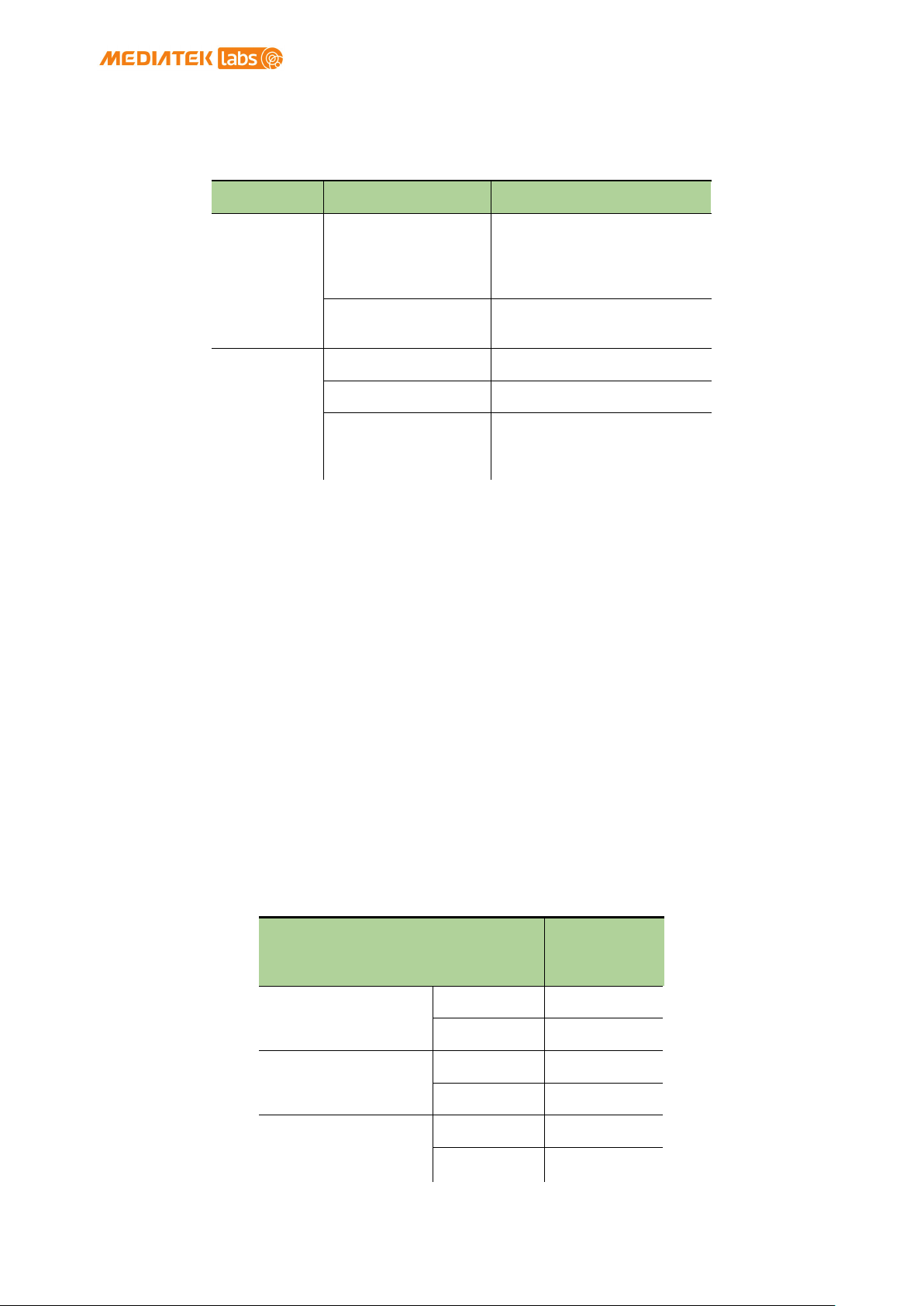
The approximate power consumption of various devices connected to LinkIt
Smart 7688 Duo is described in Table 8.
Scenario
To establish WiFi connection
Device boot up
to a SD Card via
Wi-Fi
Power
Consumption
Unauthorized reproduction or disclosure of this information in whole or in part is strictly prohibited.
© 2015, 2016 MediaTek Inc.
This document contains information that is proprietary to MediaTek Inc.
Page 14 of 38
Page 16
Approximate
Downloading a
Peak
616.6 mA
Average
347.5 mA
Downloading a
Peak
578.5 mA
Average
336.3 mA
MediaTek LinkIt™ Smart 7688 User Manual
Scenario
file to a USB
Drive via Wi-Fi
file to flash
via Wi-Fi
Table 8 Peripherals Power Consumption
Power
Consumption
1.4.7. Accessories
LinkIt Smart 7688 Duo standard package comes with the development board
only. The accessories are the same as LinkIt Smart 7688. Please refer to
1.3.7”Accessories” for more information.
1.4.8. JTAG
You can use JTAG interface to debug MT7688AN. To access JTAG interface, you
will need to unsolder resistor R95 and solder it to resistor R3 on the 7688
development board. After you’ve moved the resistor and reboot the device
you’ll activate JTAG function. The steps are:
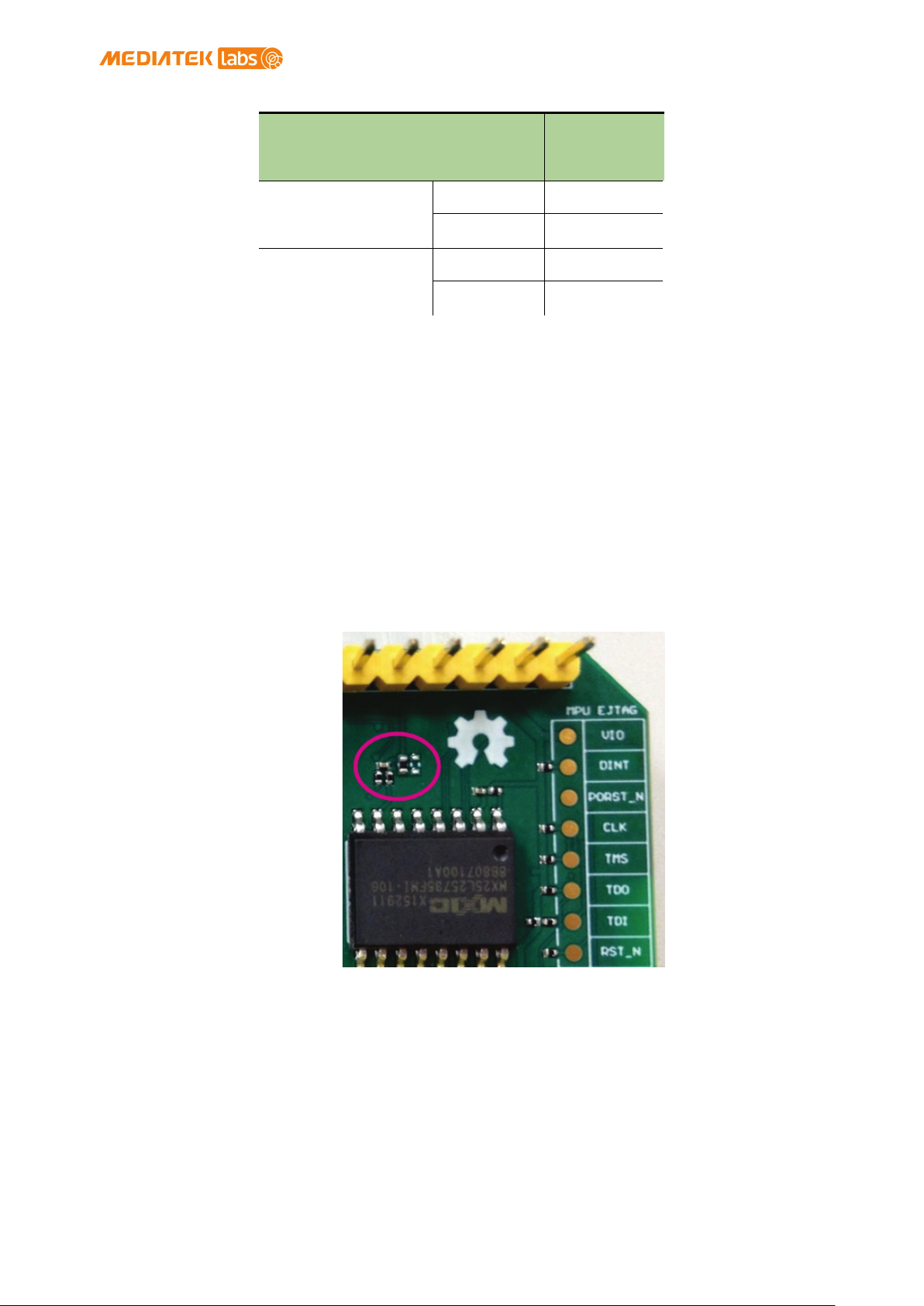
1) Find a group of resistors on the bottom side of LinkIt Smart
7688 Duo (top-right view) as circled in Figure 7.
Figure 7 JTAG resistors on LinkIt Smart 7688 Duo bottom view
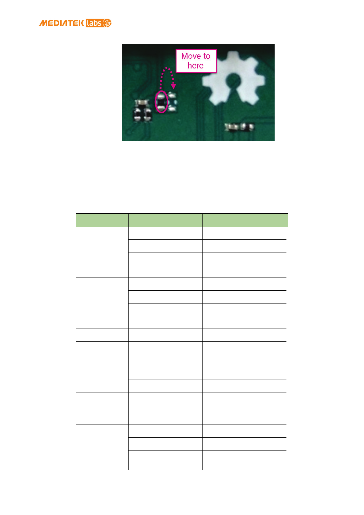
2) Next, you will move a resistor by unsoldering and soldering
it to a lower position as shown in Figure 8, after you’re
finished moving the resistor, restart the device and you
should be able to access JTAG mode.
© 2015, 2016 MediaTek Inc.
This document contains information that is proprietary to MediaTek Inc.
Unauthorized reproduction or disclosure of this information in whole or in part is strictly prohibited.
Page 15 of 38
Page 17
Category
Feature
LinkIt Smart 7688 Duo
Chipset
MT7688AN
Core
MIPS24KEc
Clock speed
580MHz
Working voltage
3.3V
Chipset
ATmega32U4
Core
Atmel AVR
Clock speed
8MHz
Working voltage
3.3V
PCB Size
Dimensions
60.8 x 26 mm
Flash
32MB
RAM
128MB DDR2
USB Power
5V (USB Micro-B)
VCC
3.3V (Pin Breakout)
3 (MT7688AN)
Voltage
3.3v
Pin Count
8 (ATmega32U4)
Voltage
3.3v
16 bits
MediaTek LinkIt™ Smart 7688 User Manual
Figure 8 Moving a resistor to access JTAG mode
1.4.9. Specifications
The key specifications of LinkIt Smart 7688 Duo development board are shown
in Table 9.
MPU
MCU
Memory
Power Source
GPIO
Pin Count
24 (ATmega32U4)
Unauthorized reproduction or disclosure of this information in whole or in part is strictly prohibited.
PWM
Max. Resolution
© 2015, 2016 MediaTek Inc.
(customizable)
This document contains information that is proprietary to MediaTek Inc.
Page 16 of 38
Page 18
Category
Feature
LinkIt Smart 7688 Duo
31.25kHz@8-bit
Timer 0 (4 sets)
2MHz@2-bit
Timer 1 & 3 (4 sets)
187.5kHz@8-bit
Timer 4 (6 sets)
Pin Count
12 (ATmega32U4)
Voltage
3.3v
External
Max. Speed
4 MHz
Set Count
1
Pin numbers
D2, D3
Speed
400K
1 (MT7688AN)
1 (ATmega32U4)
P8, P9 (MT7688AN)
D0, D1 (ATmega32U4)
115,200 bps
0.5 Mbps (MT7688AN)
Set Count
1 (MT7688AN)
Pin numbers
P6, P7
Connector type
Micro-AB
Wi-Fi
802.11 b/g/n (2.4G)
Ethernet
1-port 10/100 FE PHY
Pin numbers
P2, P3, P4, P5
Micro SD
MediaTek LinkIt™ Smart 7688 User Manual
Maximum Frequency@
Resolution
122Hz@16-bit
46.875kHz@10-bit
ADC
Interrupts
SPI/SPIS
I2C
UART (Lite)
Pin Count 8 (ATmega32U4)
Set count 1 (ATmega32U4)
Pin numbers S0, S1, S2, S3
Set Count
Pin numbers
Max. Speed
(MT7688AN)
Table 9 LinkIt Smart 7688 Duo development board specifications
Unauthorized reproduction or disclosure of this information in whole or in part is strictly prohibited.
USB Host
Communicatio
n
User Storage SD Card
© 2015, 2016 MediaTek Inc.
SDXC
This document contains information that is proprietary to MediaTek Inc.
Page 17 of 38
Page 19
MediaTek LinkIt™ Smart 7688 User Manual
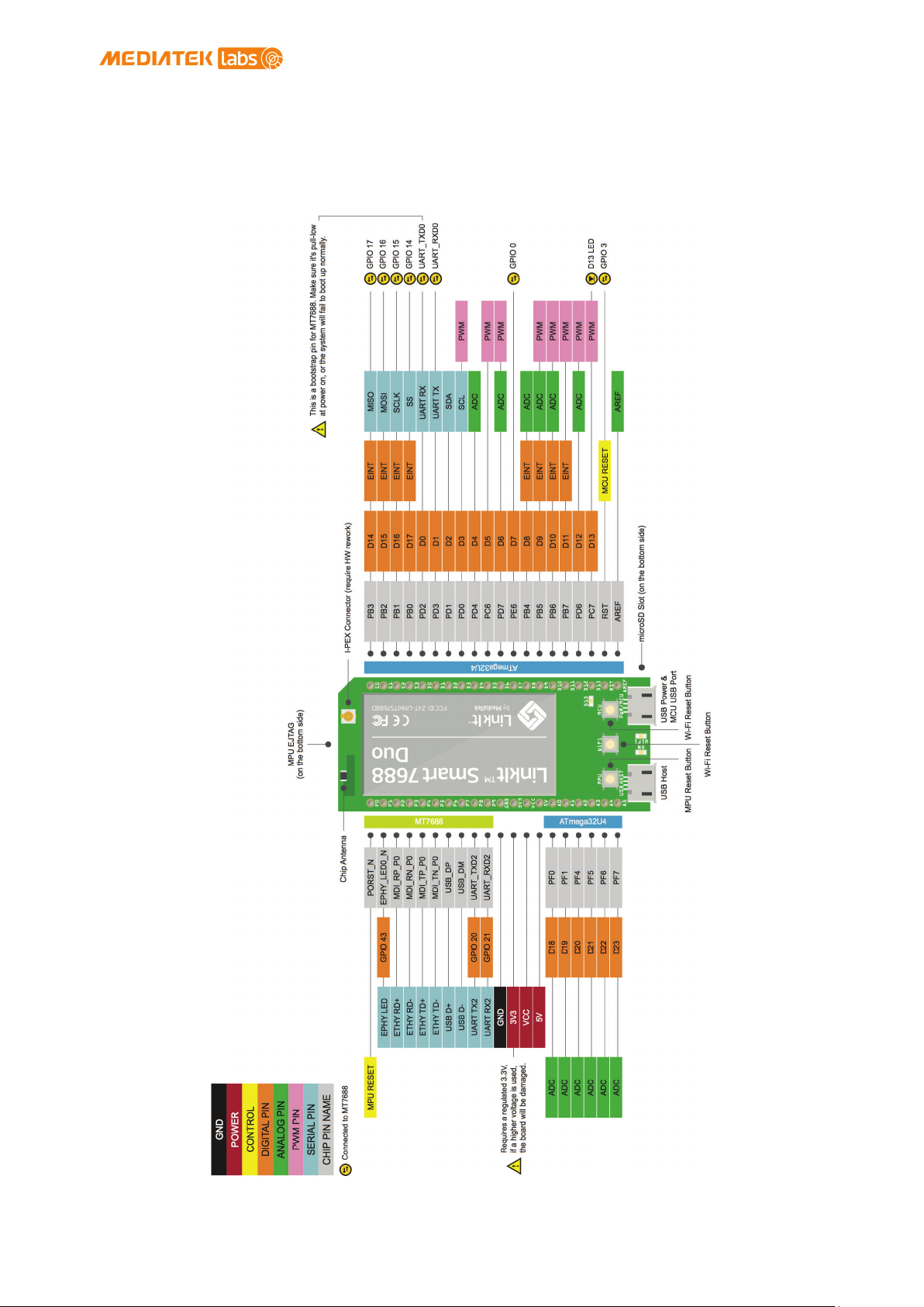
1.4.10. Pin-out Diagram
The LinkIt Smart 7688 Duo pin-out diagram is shown in the next page. You
can also download LinkIt Smart 7688 Reference Design at MediaTek Labs
website.
© 2015, 2016 MediaTek Inc.
Page 18 of 38
This document contains information that is proprietary to MediaTek Inc.
Unauthorized reproduction or disclosure of this information in whole or in part is strictly prohibited.
Page 20

MediaTek LinkIt™ Smart 7688 User Manual
1.5. Joining the MediaTek Labs Ecosystem
Wearable and Internet of Things are the next wave in the consumer gadget
revolution. MediaTek is a key player in this field, combining the best of
two worlds —the existing MediaTek ecosystem of phone manufacturers,
electronic device manufacturers, and telecom operators with the open,
vibrant maker community world.
No matter whether you’re a maker, device manufacturer, student, DIY
hobbyist, or programmer, you can use this powerful yet simple platform to
create something innovative. You can join the MediaTek LinkIt ecosystem by
registering on labs.mediatek.com
ecosystem and creating something great together.
, we look forward to you joining our
© 2015, 2016 MediaTek Inc.
This document contains information that is proprietary to MediaTek Inc.
Unauthorized reproduction or disclosure of this information in whole or in part is strictly prohibited.
Page 19 of 38
Page 21
Mac OS
Arduino IDE (LinkIt Smart
To build bootloader,
Python, Node.js development
Yes
Yes
Yes
ll need to install a virtual
and
MediaTek LinkIt™ Smart 7688 User Manual
2. Development Environment
2.1. Operating Systems
The following operating systems can be used to access LinkIt Smart 7688
development boards:
• Windows XP, 7, 8 and 10
• Mac OS X 10.9 and 10.10
• Linux Ubuntu 14.04 LTS
An overview of the OS capabilities is shown in Table 10:
OS Windows Ubuntu
7688 Duo only)
firmware and C programs
Table 10 OS Capabilities
If you are developing on a Windows computer you’
machine with Linux development environment to build bootloader, firmware
programs in C.
Yes Yes Yes
No Yes Yes
X
2.2. OpenWrt Introduction
OpenWrt is an open-source embedded Linux operating system used mainly on
embedded devices such as wireless routers. Key features of OpenWrt include
the following:
1) Comprehensive network related functions
2) Provides a fully writable file system with package
management
3) Rich and extendable feature set (over 3,400+ packages and
growing)
2.3. Network Environment
Both LinkIt Smart 7688 development board can be configured in two modes:
Access point or Station.
2.3.1. Access Point Mode
For local area network, LinkIt Smart 7688 acts as an AP. AP mode is used
when you are configuring LinkIt Smart 7688. Figure 9 illustrates how LinkIt
Smart 7688 works in a LAN environment.
This document contains information that is proprietary to MediaTek Inc.
Unauthorized reproduction or disclosure of this information in whole or in part is strictly prohibited.
© 2015, 2016 MediaTek Inc.
Page 20 of 38
Page 22
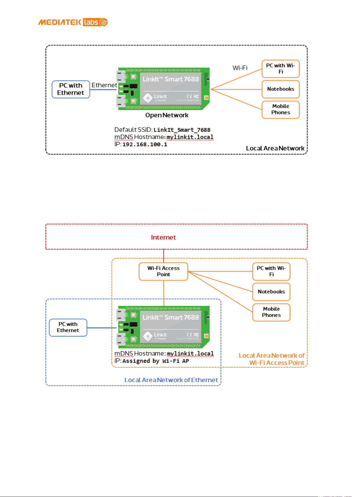
Figure 9 LinkIt Smart 7688 in AP Mode
MediaTek LinkIt™ Smart 7688 User Manual
2.3.2. Station Mode
For a network with Wi-Fi access point, LinkIt Smart 7688 acts as a station.
Station mode is used when you want to install software from OpenWrt to
LinkIt Smart LinkIt Smart 7688 HDK, for example. Figure 10 illustrates how
LinkIt Smart 7688 works in a LAN with Wi-Fi AP.
Figure 10 LinkIt Smart 7688 in Station Mode
2.4. System Configuration
This chapter describes the methods you can use to configure LinkIt Smart
7688 development board. The board uses a local domain called myLinkIt.local
and your computer needs to support mDNS to use this local domain. For
Windows 8 and later, Mac OS X and Linux, the mDNS is supported. However, if
© 2015, 2016 MediaTek Inc.
This document contains information that is proprietary to MediaTek Inc.
Unauthorized reproduction or disclosure of this information in whole or in part is strictly prohibited.
Page 21 of 38
Page 23
MediaTek LinkIt™ Smart 7688 User Manual
you’re using Windows 7, you’ll need to install Bonjour printing service to
help your computer discover LinkIt Smart 7688 (IP address) when in Station
mode on a local area network with a Wi-Fi AP.
2.4.1. Accessing Web UI
LinkIt Smart 7688 Web UI allows you to configure system information,
upgrade firmware, perform device reset and change between Wi-Fi AP and
Client mode and more. The following steps apply to Windows, Mac OS X and
Linux.
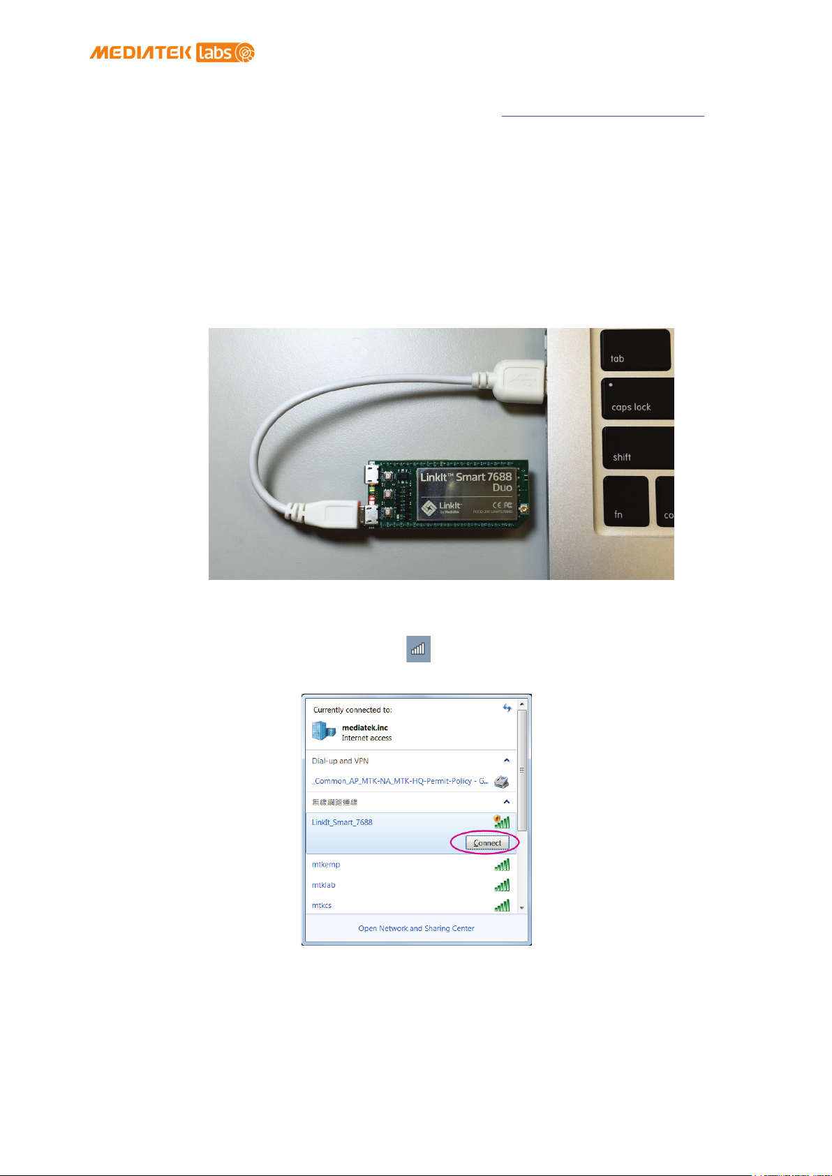
1) Power on LinkIt Smart 7688 by using any USB power source,
for example your computer and a Micro USB cable as shown in
Figure 11.
Figure 11 Connecting LinkIt Smart 7688 to a computer
2) Click the Wi-Fi icon on your computer and connect to an
access point named LinkIt_Smart_7688, as shown in Figure 12.
Figure 12 Connecting to LinkIt Smart 7688 AP
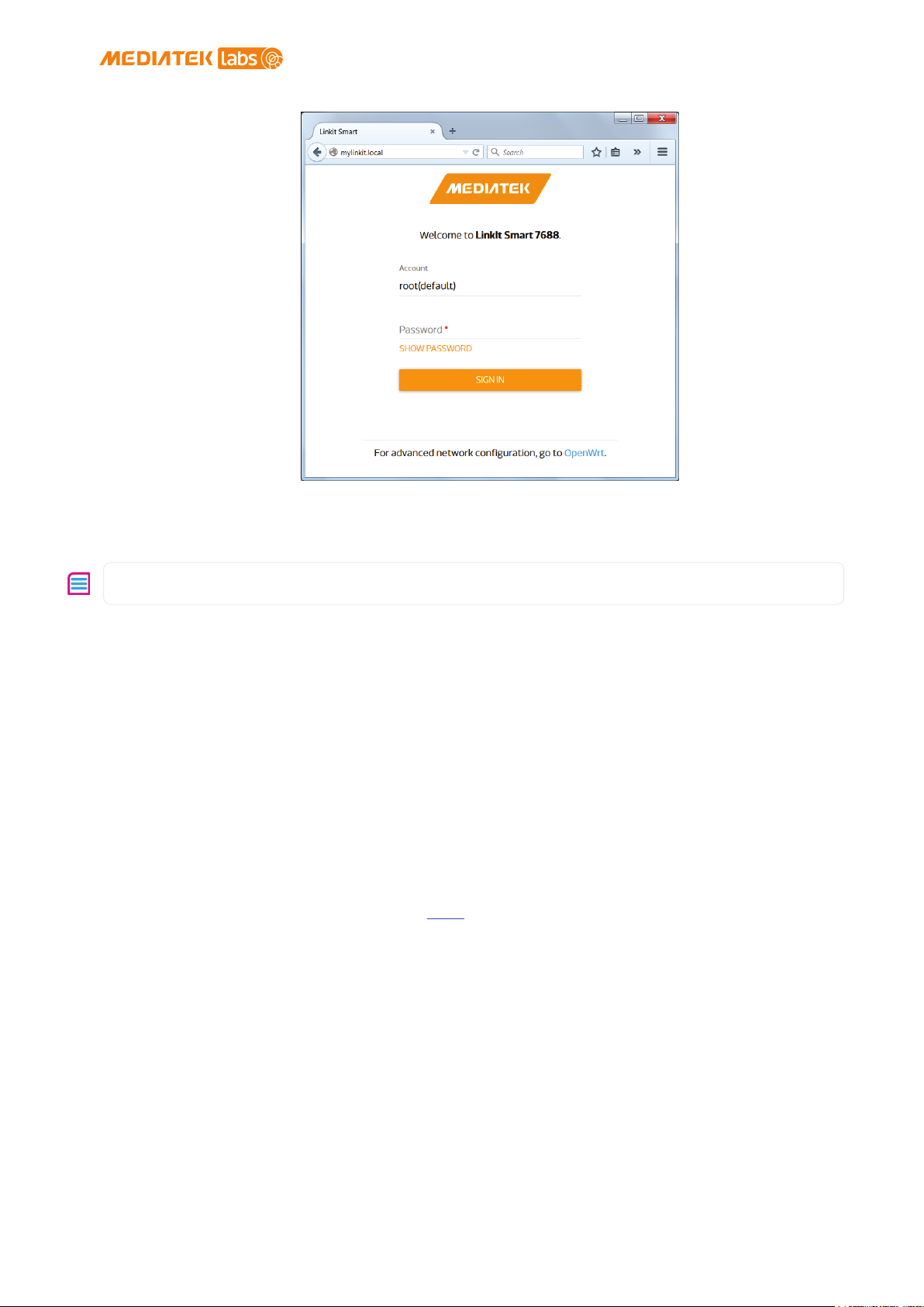
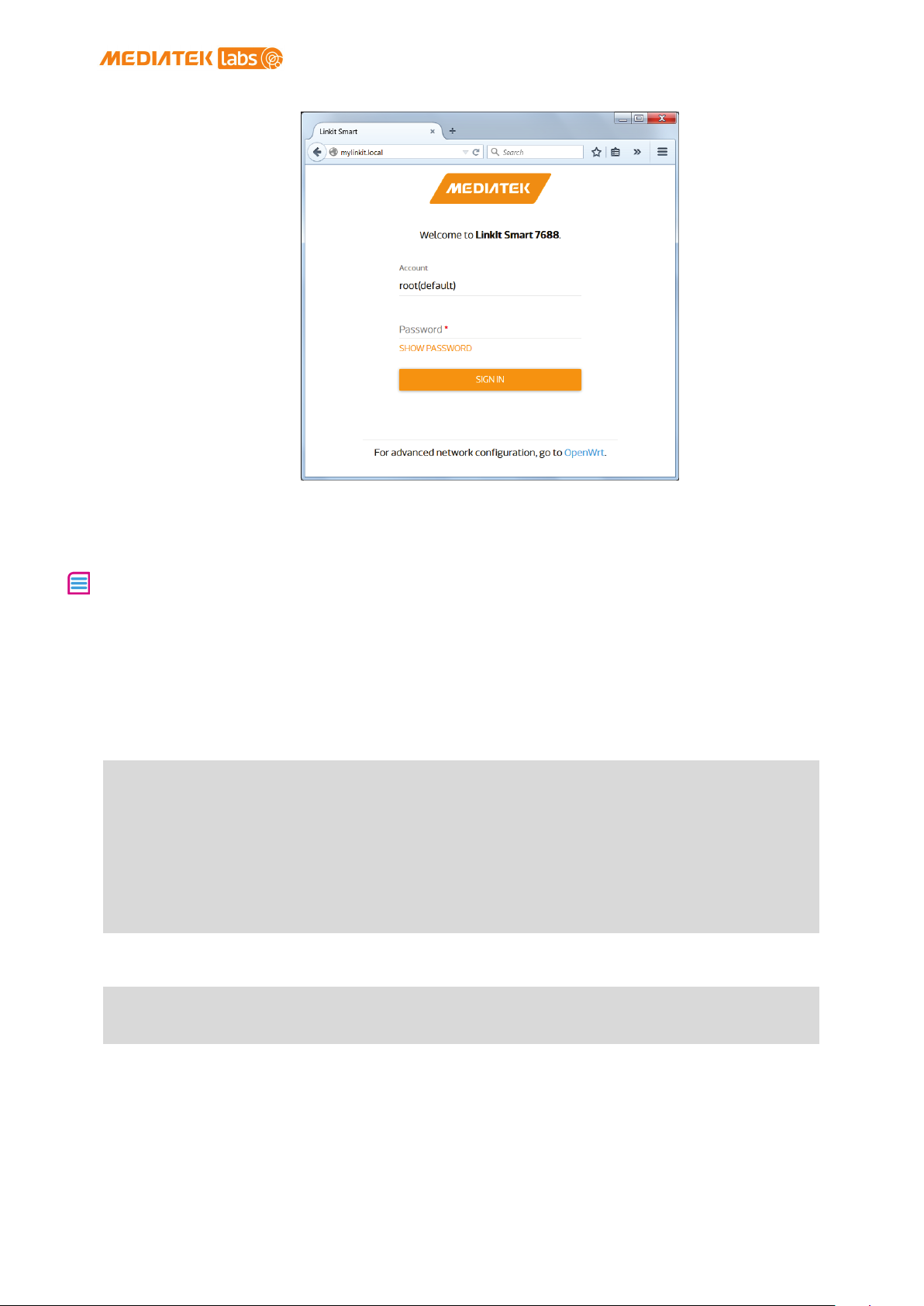
3) Open a web browser and type http://myLinkIt .local in the URL box.
The Web UI page opens as shown in Figure 13.
© 2015, 2016 MediaTek Inc.
Page 22 of 38
This document contains information that is proprietary to MediaTek Inc.
Unauthorized reproduction or disclosure of this information in whole or in part is strictly prohibited.
Page 24
Note: You must set a password before using SSH to access system console.
Figure 13 LinkIt Smart 7688 Web UI Sign In
MediaTek LinkIt™ Smart 7688 User Manual
4) Click on the Password field and set a password using at
least 6 alphanumeric characters.
2.4.2. Accessing System Console
There are two ways to access the system console on LinkIt Smart 7688
development board. They are described as follows:
2.4.3. Using SSH (Secure Socket Shell)
Before you start please make sure you’ve already set a password in the Web
UI as described in 2.4.1 “Accessing Web UI” and the LinkIt Smart 7688 is in
the same network as your computer.
For Mac and Linux, use the Terminal that’s already installed in the
computer.
For Windows:
1) Install PuTTY from here.
2) Open PuTTY and a Security Alert window will pop up, click
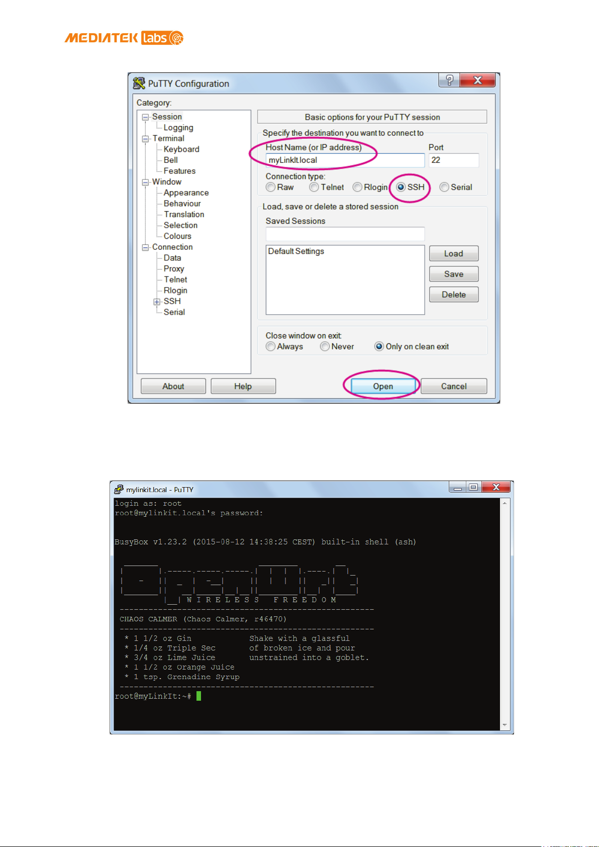
Yes. Then, in the PuTTY Configuration window, type
myLinkIt.local in the Host Name box, check the SSH radio button
and click Open as shown in Figure 14 .
© 2015, 2016 MediaTek Inc.
This document contains information that is proprietary to MediaTek Inc.
Unauthorized reproduction or disclosure of this information in whole or in part is strictly prohibited.
Page 23 of 38
Page 25
MediaTek LinkIt™ Smart 7688 User Manual
Figure 14 Using SSH in Windows PuTTY
3) In the PuTTY terminal window that opens, log in with
username root and enter the password you set previously in
the Web UI, after log in you should see a screen similar to
below.
For Mac:
© 2015, 2016 MediaTek Inc.
This document contains information that is proprietary to MediaTek Inc.
Unauthorized reproduction or disclosure of this information in whole or in part is strictly prohibited.
Page 24 of 38
Page 26

Note: Download the executable version corresponding to your OS from the
list. After installation, the COM port will be
successfully identified.
Open Terminal. In the Terminal, type ssh [email protected] at the
command line, hit return and you’ll be prompted to enter the root
password. Enter the password you set previously in the Web UI.
For Linux:
Open Terminal. In the Terminal, type ssh [email protected] at the
command line, hit return and log in using the password you set
previously.
MediaTek LinkIt™ Smart 7688 User Manual
For more information on using SSH, please reference here
.
2.4.4. Using Serial to USB Cable
You can connect to the system console of LinkIt Smart 7688 by using a
Serial (or UART) to USB cable. First, you need to check if your cable
requires driver installation; it may or may not be needed. Please check the
following sections per your OS.
Currently Supported VCP Drivers
For Windows:
1) Install driver. If you’re using a USB cable based on FTDI
chip please download and install its driver from here
you’re having problems with the latest driver, try
installing an
2) Next, you’ll need to connect the Serial to USB cable to
LinkIt Smart 7688’s UART pins in the following table as
shown in below:
older version.
. If
UART to USB Cable
RX P8
TX P9
GND GND
Table 11 USB and LinkIt Smart 7688 UART Pin Mapping
LinkIt Smart 7688 UART
pins
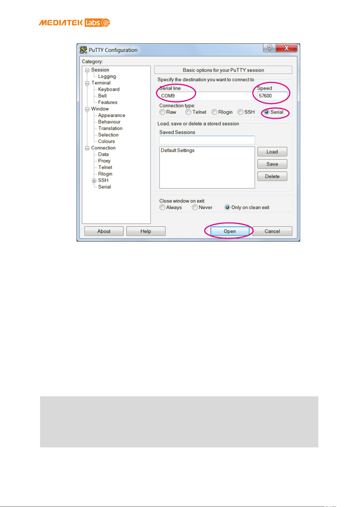
3) Open the PuTTY terminal and enter the COM port number of the
USB device found in the device manager, this number may be
different on your computer. Click on the Serial radio button,
type 57600 in Speed box and click Open, as shown in below.
© 2015, 2016 MediaTek Inc.
This document contains information that is proprietary to MediaTek Inc.
Unauthorized reproduction or disclosure of this information in whole or in part is strictly prohibited.
Page 25 of 38
Page 27
MediaTek LinkIt™ Smart 7688 User Manual
Figure 15 Using UART to USB cable to access system console in Windows
terminal
4) To exit the system console, click the X on top right of the
PuTTY windows.
For Mac:
1) Install the driver if needed. Check the cable manufacturer’s
website for driver requirements on Mac and installation
instructions.
2) Plug-in the cable and connect the cable to LinkIt Smart
LinkIt Smart 7688.
3) Open a Terminal session. You can open it at
Applications/Utilities/Terminal.
4) Type ls /dev/cu* in the Terminal. You should see a list of
devices. Look for something like cu.usbserial-XXXXXXXX where
XXXXXXXX is usually a random identifier. This is the serial
device used to access the system console. For example:
$ls /dev/cu*
/dev/cu.Bluetooth-Incoming-Port
/dev/cu.Bluetooth-Modem
/dev/cu.pablop-WirelessiAP
/dev/cu.usbserial-A6YMCQBR
© 2015, 2016 MediaTek Inc.
This document contains information that is proprietary to MediaTek Inc.
Unauthorized reproduction or disclosure of this information in whole or in part is strictly prohibited.
Page 26 of 38
Page 28

5) Use the screen utility to connect to the serial port and set
the baudrate to 57600. This is because the baudrate of the
system console is 57600 by default. For example:
MediaTek LinkIt™ Smart 7688 User Manual
$screen /dev/cu.usbserial-XXXXXXXX 57600
6) Now you should be connected to the system console. Press
ENTER in the Terminal to bring up the prompt. You'll notice
that the prompt has become different from your OS X Terminal
application, it is the LinkIt Smart 7688 prompt and it looks
like the following:
root@myLinkIt:/#
7) You’re ready to make changes to the LinkIt Smart 7688 system
through this console.
8) To exit the system console, type <CTRL>a + k, and y.
For Linux:
1) Install the driver if needed. Check the cable manufacturer’s
2) Plug-in the cable and connect the cable to LinkIt Smart
3) Open a Terminal application.
4) Type ls /dev/ttyUSB* in the Terminal. You should see a list of
$ls /dev/ttyUSB*
/dev/ttyUSB0
5) Use the screen utility to connect to the serial port and set
website for driver requirements on Ubuntu and installation
instructions.
LinkIt Smart 7688.
devices. Look for something like ttyUSB0 where 0 is usually a
random identifier. This is the serial device used to access
the system console. For example:
the baudrate to 57600. This is because the baudrate of the
system console is 57600 by default. One thing to keep in
mind is that in Ubuntu, the serial devices require dialout
group permission. Use sudo to elevate the permission, for
example:
$sudo screen /dev/ttyUSB0 57600
6) Now you should be connected to the system console. Press
ENTER in the Terminal to bring up the prompt. You'll notice
that the prompt has become different from your Linux
Terminal application, it is the LinkIt Smart 7688 prompt and
it looks like the following:
© 2015, 2016 MediaTek Inc.
This document contains information that is proprietary to MediaTek Inc.
Unauthorized reproduction or disclosure of this information in whole or in part is strictly prohibited.
Page 27 of 38
Page 29
root@myLinkIt:/#
7) You’re ready to make changes to the LinkIt Smart 7688 system
through this console.
8) To exit the system console, type <CTRL>a + k, and y.
MediaTek LinkIt™ Smart 7688 User Manual
2.4.5. Upgrading Firmware
This section describes how to upgrade the firmware on both LinkIt Smart
7688 development boards (same firmware). You can choose from one of the
following two ways to upgrade firmware:
Using Web UI:
1) Sign in the LinkIt Smart 7688 Web UI. Please see 2.4.1
“Accessing Web UI” if you haven’t signed in before.
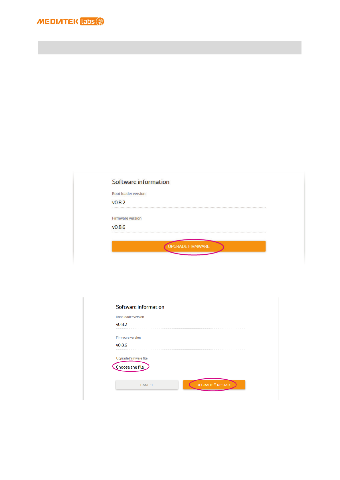
2) After you’ve signed in, click on the Upgrade firmware button
as shown in Figure 16.
Figure 16 Firmware upgrade button
3) Click under Upgrade firmware file and choose the
file. Click Upgrade & Restart button as shown in Figure 17.
Figure 17 Selecting firmware file
The firmware will upload to LinkIt Smart 7688 and the reboot will start.
This process takes about 3 minutes. When you see three short blinks on the
LinkIt Smart 7688, it indicates the firmware has been upgraded.
lks7688.img
© 2015, 2016 MediaTek Inc.
This document contains information that is proprietary to MediaTek Inc.
Unauthorized reproduction or disclosure of this information in whole or in part is strictly prohibited.
Page 28 of 38
Page 30

development board.
Warning: Do not disconnect the power source or unplug the USB drive during
bootloader upgrading process, or else the data in flash will be damaged and
you will not be able to boot up again.
Note: Performing firmware upgrade will remove all user data from the
MediaTek LinkIt™ Smart 7688 User Manual
Using USB drive :
1) Save the firmware file (lks7688.img) in the root directory
of a USB drive. You can download the latest firmware from
MediaTek Labs website.
2) Plug the USB drive to LinkIt Smart 7688.
3) Press the Wi-Fi and MPU (Reset) button at the same time,
then release the MPU Reset button only but hold the Wi-Fi
button for at least 5 seconds (Wi-Fi LED will turn off) and
release. Warning: Do not press the Wi-Fi button for longer
than 20s or it will enter boot loader mode.
4) LinkIt Smart 7688 will start to read the firmware image (WiFi LED blinks fast) and perform the firmware upgrade process
(Wi-Fi LED blinks slowly). It takes about 3 minutes to
finish the firmware upgrade process.
2.4.6. Upgrading bootloader
This section describes how to upgrade the bootloader.
Please follow these steps:
1) Save the bootloader file (
of a USB drive and name it
latest bootloader from MediaTek Labs website.
2) Plug the USB drive to LinkIt Smart LinkIt Smart 7688 HDK.
3) Press the Wi-Fi and MPU (Reset) button at the same time,
then release the MPU Reset button only but hold the Wi-Fi
button for at least 20 seconds (after 20s Wi-Fi LED will
turn on)and release.
4) LinkIt Smart 7688 development board will start to read the
bootloader (Wi-Fi LED blinks fast) and perform the
bootloader upgrade process (Wi-Fi LED blinks slowly). It
takes 2 seconds to finish the bootloader upgrade process.
lks7688.ldr) in the root directory
lks7688.ldr you can download the
2.4.7. Wi-Fi Reset
Press the Wi-Fi Reset button for at least 5 seconds and release. The device
will go into AP mode.
2.4.8. Factory Reset
This section describes how to do factory reset on LinkIt Smart 7688
development board. Factory reset will erase all user data from the board,
so proceed with caution. Choose from one of the following two ways to
perform factory reset.
Using Web UI
© 2015, 2016 MediaTek Inc.
This document contains information that is proprietary to MediaTek Inc.
Unauthorized reproduction or disclosure of this information in whole or in part is strictly prohibited.
Page 29 of 38
Page 31

1) Sign in the Web UI 2.4.1” Accessing Web UI” and click the
Reset button under Factory Reset, as shown in Figure 18.
Figure 18 Factory Reset using LinkIt Smart 7688 Web UI
MediaTek LinkIt™ Smart 7688 User Manual
Using the Wi-Fi Reset button
After LinkIt Smart 7688 is boot up (power LED solid on, Wi-Fi LED), press
the Wi-Fi Reset button for at least 20 seconds and release. Please see
Figure 1 for Wi-Fi Reset button locations. LinkIt Smart 7688 development
board will reboot to default settings and all user data will be eliminated
from the board, so proceed with caution.
2.4.9. Connecting LinkIt Smart 7688 To a network with Wi-Fi
Access Point
This section describes the two ways LinkIt Smart 7688 development board
connects to a network that is not in the same network as the computer it’s
connected to. To connect to an access point, LinkIt Smart 7688 needs to be
in Station mode.
Using OpenWrt’s UCI (Unified Configuration Interface)
2.4.10. Open a system console and enter the following commands
to change LinkIt Smart 7688 to station mode ( For more
information on system console, please see 2.4.1
“Accessing Web UI
LinkIt Smart 7688 Web UI allows you to configure system information,
upgrade firmware, perform device reset and change between Wi-Fi AP and
Client mode and more. The following steps apply to Windows, Mac OS X and
Linux.
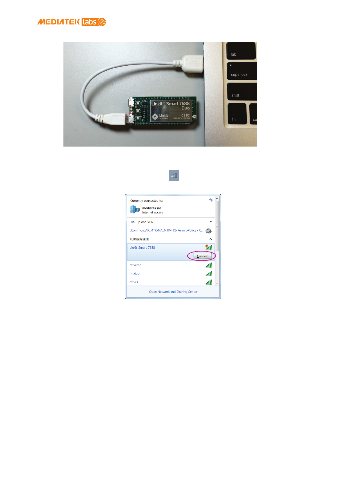
2) Power on LinkIt Smart 7688 by using any USB power source,
for example your computer and a Micro USB cable as shown in
Figure 11.
© 2015, 2016 MediaTek Inc.
This document contains information that is proprietary to MediaTek Inc.
Unauthorized reproduction or disclosure of this information in whole or in part is strictly prohibited.
Page 30 of 38
Page 32
MediaTek LinkIt™ Smart 7688 User Manual
Figure 11 Connecting LinkIt Smart 7688 to a computer
3) Click the Wi-Fi icon on your computer and connect to an
access point named LinkIt_Smart_7688, as shown in Figure 12.
Figure 12 Connecting to LinkIt Smart 7688 AP
4) Open a web browser and type http://myLinkIt .local in the URL box.
The Web UI page opens as shown in Figure 13.
© 2015, 2016 MediaTek Inc.
Page 31 of 38
This document contains information that is proprietary to MediaTek Inc.
Unauthorized reproduction or disclosure of this information in whole or in part is strictly prohibited.
Page 33
Note: You must set a password before using SSH to access system console.
Figure 13 LinkIt Smart 7688 Web UI Sign In
MediaTek LinkIt™ Smart 7688 User Manual
5) Click on the Password field and set a password using at
least 6 alphanumeric characters.
1) Accessing System Console” ):
In this example, the following AP is used:
AP SSID: MyAP
Encryption type: PSK2
Password: 12345678
# uci set wireless.sta.ssid=MyAP
# uci set wireless.sta.encryption=psk2
# uci set wireless.sta.key=12345678
# uci set wireless.sta.disabled=0
# uci commit
# wifi down
# wifi up
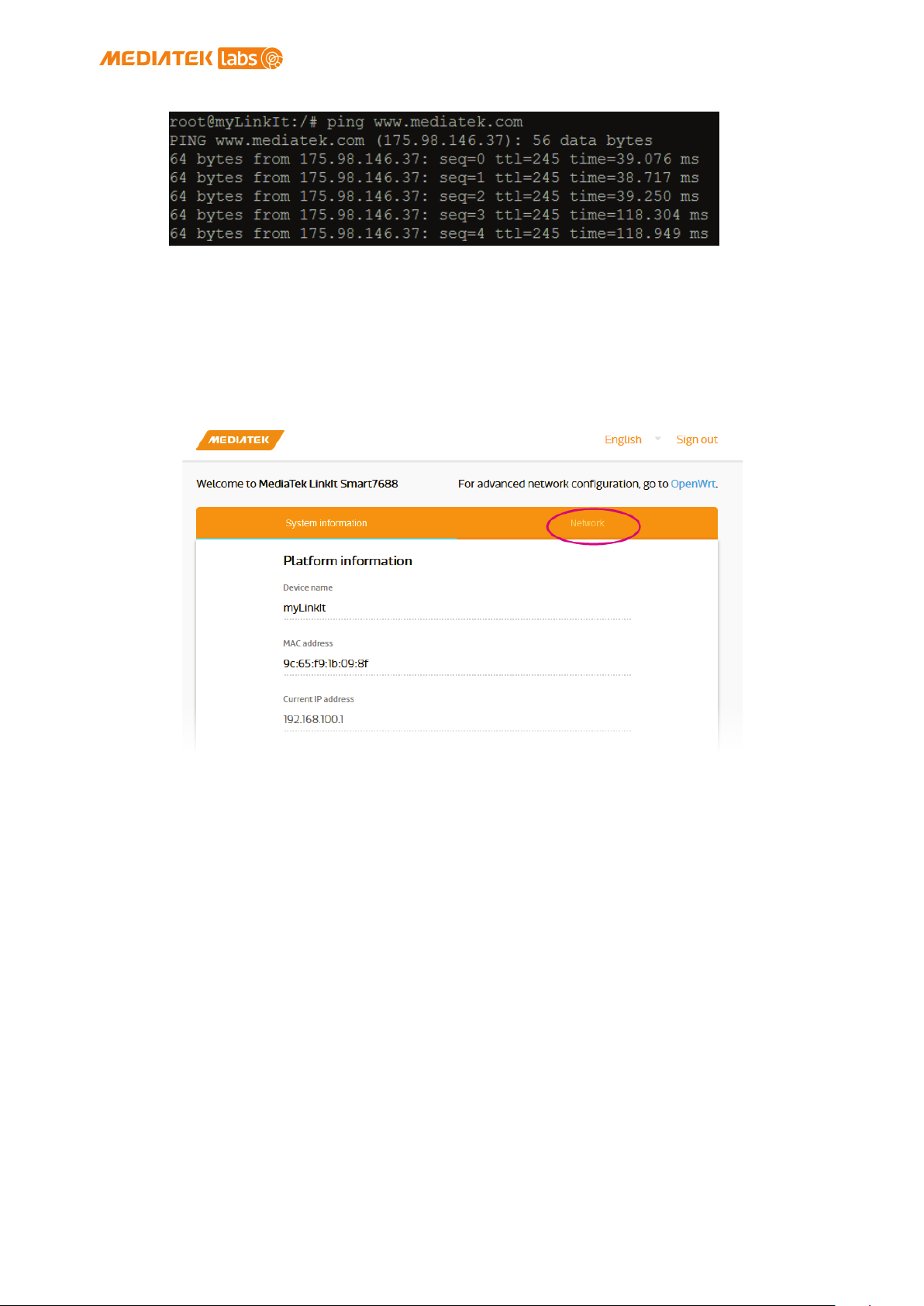
2) Now check if you’ve established network connection by typing
the following command in the terminal window:
# ping www.mediatek.com
If you see a screen similar to Figure 19, congratulations, you’ve
connected to the Wi-Fi network’s AP.
© 2015, 2016 MediaTek Inc.
This document contains information that is proprietary to MediaTek Inc.
Unauthorized reproduction or disclosure of this information in whole or in part is strictly prohibited.
Page 32 of 38
Page 34
MediaTek LinkIt™ Smart 7688 User Manual
Figure 19 LinkIt Smart 7688 in Station mode connected to a Wi-Fi AP
Using Web UI
Open a browser and type in myLinkIt.local. Please see 2.4.1”Accessing Web UI”
if you’ve not signed in before.
1) Click Network button on upper right as shown in Figure 20
Figure 20 Change networking setting in Web UI
2) Select the station mode and click the Refresh button or
downward arrow on the right to find the AP to connect to.
After you’ve selected the AP, enter password if required.
Click Configure & Restart button to finish as shown in Figure
21.
© 2015, 2016 MediaTek Inc.
Page 33 of 38
This document contains information that is proprietary to MediaTek Inc.
Unauthorized reproduction or disclosure of this information in whole or in part is strictly prohibited.
Page 35
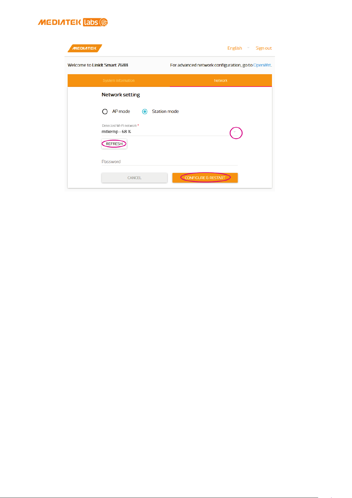
Figure 21 Changing to Station mode in Web UI
MediaTek LinkIt™ Smart 7688 User Manual
3) A message window will pop up letting you know the device is
connecting to the AP you’ve selected.
4) Notice the Wi-Fi LED, it should blink once a second, this
indicates LinkIt Smart 7688 is in Station mode.
5) To change LinkIt Smart 7688 back to AP mode, press the Wi-Fi
Reset button for at least 5 seconds and release. When you
see three short blinks on Wi-Fi LED, it is in AP mode.
2.4.11. Viewing System Information from the Web UI
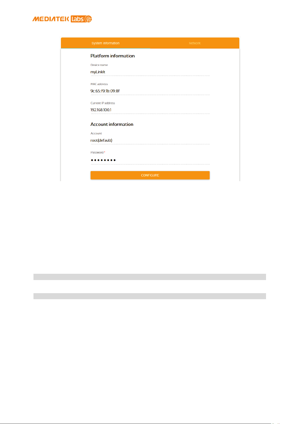
You can view LinkIt Smart 7688’s system information from any browser. After
you’ve connected the LinkIt Smart 7688 to a network, open a browser and
type http://myLinkIt.local in the URL box and sign in 2.4.1”Accessing Web UI”.
Click the Configure button under System information and the following
information will display, as shown in Figure 22:
• Device name
• MAC address
• Current IP address
• Account/Password
• Bootloader/Firmware version
© 2015, 2016 MediaTek Inc.
This document contains information that is proprietary to MediaTek Inc.
Unauthorized reproduction or disclosure of this information in whole or in part is strictly prohibited.
Page 34 of 38
Page 36
> ls /Media/USB-A1
> ls /Media/SD-P1
MediaTek LinkIt™ Smart 7688 User Manual
Figure 22 System Information in LinkIt Smart 7688 Web UI
2.5. Accessing the USB drive and the SD card
When a USB drive or SD card is inserted into LinkIt Smart 7688, they can be
accessed under /Media/SD* or /Media/USB* (The device name displayed varies
depending on the number of drives you use and the number of partitions
available on the USB drive or SD card).
You can use the following commands to check the contents of the USB drive
and SD card:
• In this example, a USB drive named USB-A1 is used:
• In this example, a SD card named SD-P1 is used:
This document contains information that is proprietary to MediaTek Inc.
Unauthorized reproduction or disclosure of this information in whole or in part is strictly prohibited.
© 2015, 2016 MediaTek Inc.
Page 35 of 38
Page 37

MediaTek LinkIt™ Smart 7688 User Manual
Federal Communication
Commission Interference
Statement
This device complies with Part 15 of the FCC Rules. Operation is subject to
the following two conditions: (1) This device may not cause harmful
interference, and (2) this device must accept any interference received,
including interference that may cause undesired operation.
This equipment has been tested and found to comply with the limits for a
Class B digital device, pursuant to Part 15 of the FCC Rules. These limits
are designed to provide reasonable protection against harmful interference
in a residential installation. This equipment generates, uses and can
radiate radio frequency energy and, if not installed and used in accordance
with the instructions, may cause harmful interference to radio
communications. However, there is no guarantee that interference will not
occur in a particular installation. If this equipment does cause harmful
interference to radio or television reception, which can be determined by
turning the equipment off and on, the user is encouraged to try to correct
the interference by one of the following measures:
Reorient or relocate the receiving antenna.
Increase the separation between the equipment and receiver.
Connect the equipment into an outlet on a circuit different from that
to which the receiver is connected.
Consult the dealer or an experienced radio/TV technician for help.
FCC Caution:
Any changes or modifications not expressly approved by the party
responsible for compliance could void the user's authority to operate
this equipment.
This transmitter must not be co-located or operating in conjunction
with any other antenna or transmitter.
Radiation Exposure Statement:
This equipment complies with FCC radiation exposure limits set forth for an
uncontrolled environment. This equipment should be installed and operated
with minimum distance 20cm between the radiator & your body.
This device is intended only for OEM integrators under the following
conditions:
1) The antenna must be installed such that 20 cm is maintained between the
antenna and users, and the maximum antenna gain allowed for use with this
device is -3 dBi.
2) The transmitter module may not be co-located with any other transmitter
or antenna.
As long as 2 conditions above are met, further transmitter test will not be
required. However, the OEM integrator is still responsible for testing
their end-product for any additional compliance requirements required with
this module installed
IMPORTANT NOTE: In the event that these conditions can not be met (for
example certain laptop configurations or co-location with another
transmitter), then the FCC authorization is no longer considered valid and
© 2015, 2016 MediaTek Inc.
This document contains information that is proprietary to MediaTek Inc.
Unauthorized reproduction or disclosure of this information in whole or in part is strictly prohibited.
Page 36 of 38
Page 38

MediaTek LinkIt™ Smart 7688 User Manual
the FCC ID can not be used on the final product. In these circumstances,
the OEM integrator will be responsible for re-evaluating the end product
(including the transmitter) and obtaining a separate FCC authorization.
End Product Labeling
This transmitter module is authorized only for use in device where the
antenna may be installed such that 20 cm may be maintained between the
antenna and users. The final end product must be labeled in a visible area
with the following: “Contains FCC ID: Z4T-LINKITS7688”. The grantee's FCC
ID can be used only when all FCC compliance requirements are met.
Manual Information To the End User
The OEM integrator has to be aware not to provide information to the end
user regarding how to install or remove this RF module in the user’s manual
of the end product which integrates this module. The end user manual shall
include all required regulatory information/warning as show in this manual.
© 2015, 2016 MediaTek Inc.
Page 37 of 38
This document contains information that is proprietary to MediaTek Inc.
Unauthorized reproduction or disclosure of this information in whole or in part is strictly prohibited.
 Loading...