

Page 1

Linkam Scientific I nstruments
RH95 Humidity Controller
1.1.1
USER GU IDE
Page 2

...................................................................................................................................................................3Introduction
...................................................................................................................................................................4Importa nt Notices
.................................................................................................................................................................................................... 4Warranty
.................................................................................................................................................................................................... 4Technical Support
.................................................................................................................................................................................................... 4Feedback
...................................................................................................................................................................5Safety Informa tion
.................................................................................................................................................................................................... 5Important notice
.................................................................................................................................................................................................... 5Requirements for safe use
.................................................................................................................................................................................................... 5Caution Labels and Indicators
.................................................................................................................................................................................................... 5Equipment Mainten ance
...................................................................................................................................................................6Informat ions de sécurité
.................................................................................................................................................................................................... 6Not e importante
.................................................................................................................................................................................................... 6Exigences en matiè re de sécurité d 'utilisation
.................................................................................................................................................................................................... 6Étiquet tes d' avertisseme nt et indicateurs
.................................................................................................................................................................................................... 6Entretien de l'appareil
...................................................................................................................................................................7System Overview
.................................................................................................................................................................................................... 8Connecting your RH95 Controller
Bac k Panel Connections
Connecting the RH95 to the humidity chamber
Connecting the RH95 to a Linkam Heating Stage
.............................................................................................................................................................................................. 8
USB Connector
RS232 C onn ector
Humidity sensor connector
Power socket
Transit Scre w Holder
Air Inlet Connector
.............................................................................................................................................................................................. 9
.............................................................................................................................................................................................. 10
........................................................................................................................................................................... 8
........................................................................................................................................................................... 8
........................................................................................................................................................................... 8
........................................................................................................................................................................... 8
........................................................................................................................................................................... 8
........................................................................................................................................................................... 8
...................................................................................................................................................................12Using the RH95 Controller
.................................................................................................................................................................................................... 12Filling the wat er bottle
.................................................................................................................................................................................................... 14Desiccant conditioning
.................................................................................................................................................................................................... 14Setting the humidity level
.................................................................................................................................................................................................... 15RH95 settings and configuration
RH95 status
Humidity sensor details
.............................................................................................................................................................................................. 15
.............................................................................................................................................................................................. 15
.................................................................................................................................................................................................... 15Touchscreen Calibration
...................................................................................................................................................................16Validating the humidity reading
...................................................................................................................................................................19Declarat ion of Conformity
...................................................................................................................................................................20Technical Specifications
Table of Contents
v1.1.1
2
© 2017 Linkam Scientific Instruments Ltd.
Page 3

Introduction
Thank you for purchasing your Linkam equipment, please take a moment to read this manual before setting up the equipment.
If you have purchased control software, please install the software first.
See your software manual for further installation instructions.
v1.1.1
© 2017 Linkam Scientific Instruments Ltd.
3
Page 4

Important Notices
Please register your products by going to www.linkam.co.uk and clicking on the activate warranty link. You will need to register your equipment with
us to:
Activate your warranty and technical support.
Access the online setup videos.
Warranty
This equipment has a warranty against defects in material and workmanship for a period of 12 months from the date of shipping. Linkam will either
repair or replace products that prove to be defective. For warranty service or repair, this product must be returned to Linkam or a designated
service facility.
The warranty shall not apply to defects resulting from interfacing, unauthorized modification or misuse, operation outside of the environmental
specifications for the product, or improper site preparation or maintenance.
Technical Support
Any technical questions or queries should be addressed to the Technical Support Department at the address shown below and on the back of this
manual.
Tel: +44(0)1737 363 476
Email: [email protected]
Feedback
Your feedback will be greatly appreciated, please email us directly [email protected]
v1.1.1
4
© 2017 Linkam Scientific Instruments Ltd.
Page 5

Safety Informa t ion
Important notice
Please check that your Linkam equipment has not been damaged during transport.
If there is any evidence of external damage to any of the electrical items:-
do not connect power to the power supply or the RH95 unit.
Contact Linkam Scientific Instruments Ltd or their appointed distributor immediately. Your warranty may be impaired if Linkam is not informed of
any transport damage within 7 working days of delivery.
Requirements for safe use
1. Read all of this guide before using the equipment. Save these instructions for later use.
2. Follow all warnings and instructions marked on any of your Linkam equipment, or contained within the manuals.
3. To prevent electric shock, do not remove the cover of the equipment.
4. Never use the equipment if any of the cables, including the power cord, have been damaged. Do not allow any heavy objects to rest on the
power cord. Never lay the power cord on the floor.
5. Do not obstruct any ventilation holes. Do not attempt to insert anything into these openings. Provide adequate ventilation of at least
75mm all around the equipment.
6. The mains cord set is the overall disconnect and must remain accessible.
7. If the equipment is used in a manner not specified by the manufacturer, the protection provided by the equipment may be impaired.
8. Do not expose the equipment to water. If for any reason it gets wet, then remove the power cord from the power supply and contact Linkam
Scientific Technical Support.
9. The equipment is not intended to be used outdoors.
10. Each product is equipped with a 3-wire grounded (earth) power plug or a free-end 3 wire power cord. The plug only fits into a grounded-type
outlet. The free-end power cord should be connected to a correctly grounded 3-wire power outlet. Do not defeat the purpose of the
grounded (earth) type plug.
Free - end power cords are colour coded as follows:-
11. The power cord must be an appropriately rated and approved cord-set for the country it is being used in.
12. Only use an appropriately rated power supply, that is approved for the country it is being used in.
13. If any problems occur then remove the power cord from the power supply and contact Linkam Scientific Technical Support.
14. NO attempt should be made to repair or modify the equipment in any way. Any servicing should be carried out by qualified service
personnel. Do not remove the cover from the equipment unless the power cord has been removed from the mains outlet.
15. After servicing the safe state of the equipment must be checked.
Colour Function
Brown Live
Blue Neutral
Green/Yellow Earth (Ground)
Caution Labels and Indicators
This safety symbol is seen on the RH95 instrument rating label and warns the user :
·
Do not make or remove any connections while the unit is powered on.
·
Do not remove the cover.
·
Servicing should only be done by qualified service personnel.
Equipment Mainten ance
The equipment does not require any regular maintenance. Contact Linkam should you require any maintenance.
Before cleaning the case or front panel of the equipment, remove power from the unit. Use a small quantity of isopropyl alcohol (IPA) on a soft cloth
and gently wipe the surface.
v1.1.1
© 2017 Linkam Scientific Instruments Ltd.
5
Page 6

Informat ions de sécurité
Not e importante
Veuillez vérifier que votre appareil Linkam n'a pas été endommagé pendant le transport.
S'il présente une trace quelconque d'endommagement aux éléments électriques:
ne pas brancher l'alimentation à l'alimentation ou à l'unité RH95
Contactez Linkam Scientific Instruments Ltd ou son distributeur désigné immédiatement. Votre garantie pourrait être réduite si Linkam n'est pas
informée de tout dommage causé par le transport dans les 7ouvrables suivant la livraison.
Exigences en matiè re de sécurité d 'utilisation
1. Lisez ce guide intégralement avant d'utiliser l'appareil. Conservez ces instructions pour un usage ultérieur.
2. Suivez toutes les mises en garde et instructions marquées sur toute pièce de votre appareil, ou figurant dans les manuels.
3. Pour prévenir l'électrocution, n'enlevez pas le couvercle de l'appareil.
4. N'utilisez jamais l'appareil si le cordon d'alimentation a été endommagé. Ne laissez pas d'objets lourds appuyés sur le cordon
d'alimentation. Ne posez jamais le cordon d'alimentation sur le sol.
5. Le secteur cordon est la déconnexion globale et doit rester accessible.
6. Si l'équipement est utilisé d'une manière non spécifiée par le fabricant, la protection fournie par l'équipement peut être altérée.
7. N'obstruez aucun des orifices de ventilation. N'essayez pas d'insérer quoi que ce soit dans ces ouvertures. Prévoyez un espace de
ventilation adéquat d'au moins 75autour de l'appareil.
8. N'exposez pas l'appareil à l'eau. Si pour une quelconque raison l'appareil est mouillé, retirez le cordon d'alimentation de la prise de courant
et contactez le support technique de Linkam.
9. L'appareil n'est pas destiné à un usage à l'extérieur.
10. Chaque produit est équipé d'une fiche d'alimentation mise à la terre ou d'un cordon d'alimentation avec 3 fils à extrémité libre. La fiche ne
s'insère que dans une prise de courant mise à la terre. Le cordon d'alimentation à extrémités libres doit être raccordé à une prise de
courant à 3 fils correctement mise à la terre. N'empêchez pas le fonctionnement de la fiche mise à la terre.
Les cordons d'alimentation à extrémité libre suivent les codes couleur suivants:
Couleur Fonction
Marron conducteur de phase
Bleu conducteur neutre
Vert/jaune mise à la terre
11. Le cordon d'alimentation doit être constitué d'un ensemble de câbles répondant aux caractéristiques nominales et approuvé dans le pays
d'utilisation.
12. Utilisez uniquement une alimentation nominale appropriée, qui est approuvé pour le pays, il est utilisé po.
13. Si un problème survient, débranchez le cordon d'alimentation de la prise de courant et contactez le support technique de Linkam.
14. Aucune tentative ne devrait être fait pour réparer ou de modifier l'équipement en aucune façon. Toute réparation doit être effectuée par un
personnel qualifié . Ne pas retirer le couvercle de l'appareil, sauf le cordon d'alimentation a été retiré de la prise secteur.
15. Après l'entretien de l'état de sécurité de l'équipement doit être vérifiée.
Étiquet tes d' avertisseme nt et indicateurs
Ce symbole de sécurité est visible sur l'instrument étiquette signalétique RH95 et avertit l'utilisateur:
·
N'effectuez ou n'enlevez aucun raccordement quand l'appareil est sous tension.
·
N'enlevez pas le couvercle.
·
L'entretien doit être effectué exclusivement par du personnel qualifié.
Entretien de l'appareil
L'appareil ne nécessite pas d'entretien régulier. Contactez Linkam si vous souhaitez procéder à un entretien.
Avant de nettoyer le boîtier ou le panneau avant de l'appareil, débranchez le cordon secteur de la prise de courant. Utilisez une petite quantité
d'alcool ispropylique (IPA) sur un chiffon doux et frottez délicatement la surface.
v1.1.1
6
© 2017 Linkam Scientific Instruments Ltd.
Page 7
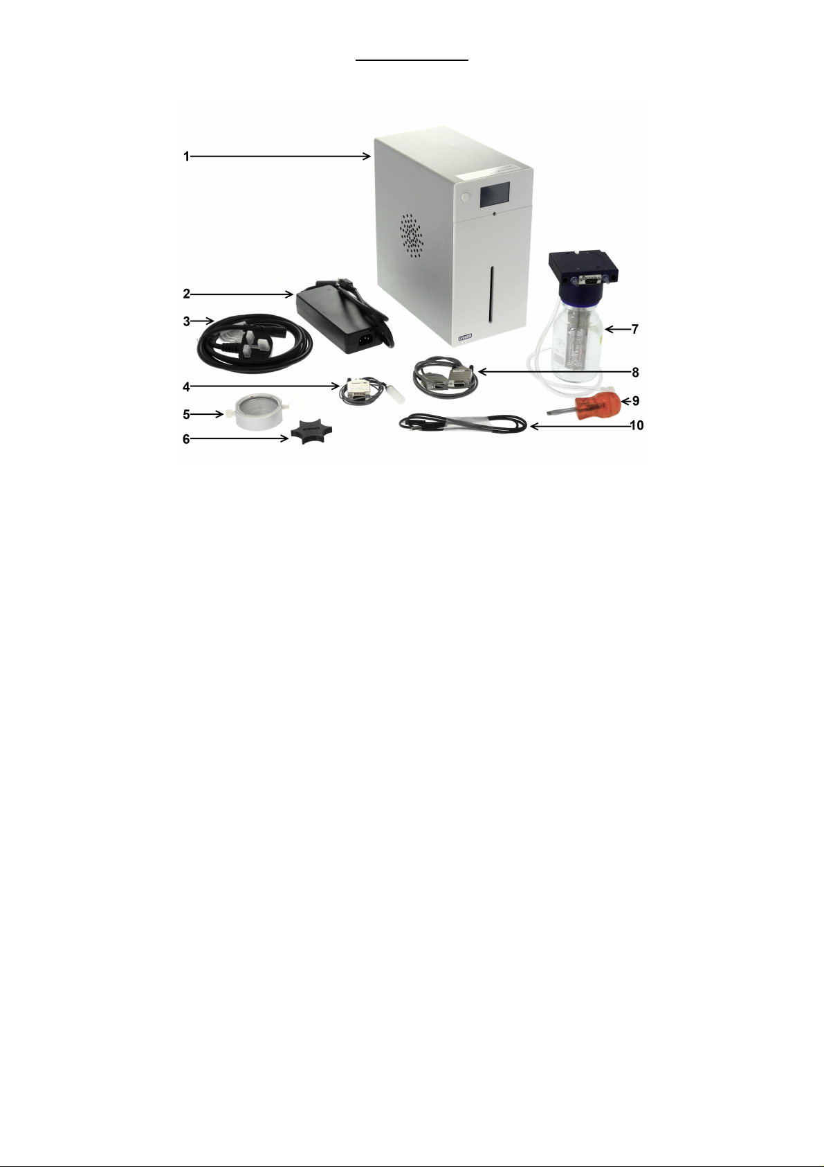
The RH95 system contains the following components:
System Overview
1. RH95 Controller
2. RH95 power adaptor
3. Mains lead
4. Humidity sensor and cable for humidity chamber
5. Humidity chamber
6. Humidity chamber tool
7. RH water bottle
8. Humidity data RS232 cable (only included when a T95 controller is supplied)
9. Screwdriver
10. USB Type A to micro B cable for firmware upgrades
IMPORTANT NOTE : The humidity sensor (4) is s us ceptible to damage from electrostatic discharge. Please observe proper ESD handling precautions when
handling the humidity sensor or sensor cable as s embly
v1.1.1
© 2017 Linkam Scientific Instruments Ltd.
7
Page 8
Connecting your RH95 Controller
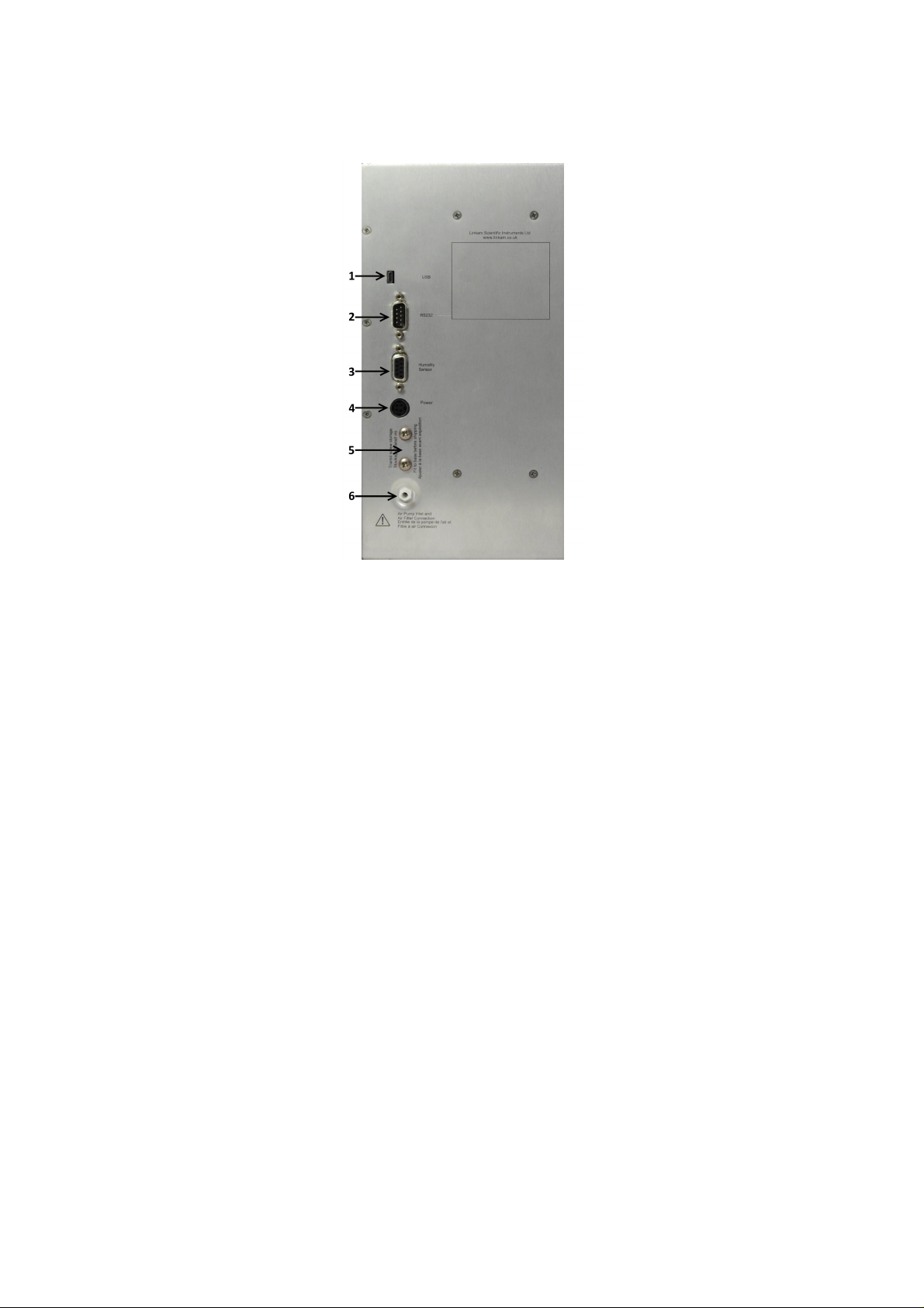
This section describes the connections on the back panel of the RH95 humidity controller and their purpose.
Back Pa nel Connections
Warning: To a v oid any da ma ge to the RH95, switch the unit off before connecting or disconnecting any connection.
1: Micro USB connector (currently used for firmware upgrade only).
2: RS232 Connector
3: Humidity Sensor Connector
4: Power socket
5: Transit screw holder
6: Air Inlet connector
USB Connector
At present this is only used for updating the firmware in the RH95.
RS232 Connector
The RS232 connector is intended to allow the RH95 controller to be connected to a Linkam controller using the humidity data RS232 cable.
Humidity sensor connector
The humidity sensor connector is used to connect the RH95 to the humidity sensor cable.
Power socket
For connection to the power supply provided with the RH95 unit.
Note: DO NOT connect the power transf ormer to the RH95 while the transformer is powered on. First connect the transf ormer to the RH95, and then
connect the mains power to the transformer.
Trans it Screw Holder
The transit screw holder should be used to hold the transit screws, which hold the internal pump secure during shipping. These are found on the
underside of the controller and should be removed before use. Remember to re-secure the pump with these transit screws before shipping.
Air Inlet Connector
This is the port that supplies air to the RH95 controller for humidification / drying. Blocking access to this port will prevent the RH95 from functioning.
Important Note: Only suitable for use with gas a t a tmospheric pressure. DO NO T f low pressurized gas into this port.
v1.1.1
8
© 2017 Linkam Scientific Instruments Ltd.
Page 9
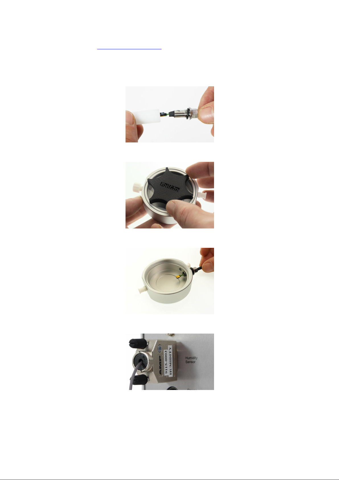
Connecting the RH95 to the humidity chamber
Your RH95 system includes a small humidity chamber that can be used to test your samples at ambient temperature. To connect the RH95
controller to the supplied humidity chamber follow the below procedure:
Note: This chamber is also used when validating the humidity reading.
IMPORTANT NOTICE: T he humidity sensor is extremely s ensitive to contaminants - DO N O T touch the exposed chip or allow any thing to come into
contact with it. These sensors cannot be repaired if broken or contaminated, and are not covered by warranty.
1. Carefully remove the cap protecting the humidity sensor. Do not touch the exposed chip on the humidity sensor.
2. Remove the lid of the humidity chamber using the provided tool, as shown:
3. Screw the sensor into the chamber, being very careful not to damage the fragile sensor.
4. Connect the 9 pin connector for the sensor to the port on the back of the RH95 marked 'Humidity Sensor'
v1.1.1
© 2017 Linkam Scientific Instruments Ltd.
9
Page 10
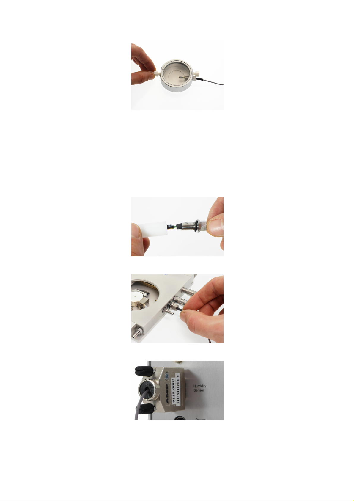
5. Connect the humidity tube from the front of the RH95 to the port on the humidity chamber opposite the sensor, as shown:
Note: Do not connect the humidity tube to the same side of the chamber as the sensor, as this will aff ect the readings.
6. Replace the lid of the humidity chamber. You are now ready to control the humidity in the chamber.
Connecting the RH95 to a Linkam Heating Stage
If you have purchased a Linkam heating stage with humidity capability to go with your RH95 controller, follow these instructions to connect it:
IMPORTANT NOTICE: T he humidity sensor is extremely s ensitive to contaminants - DO N O T touch the exposed chip or allow any thing to come into
contact with it. These sensors cannot be repaired if broken or contaminated, and are not covered by warranty.
1. Carefully remove the cap protecting the humidity sensor.
2. Screw the humidity sensor into the provided threaded hole in the Linkam heating stage, being very careful not to touch the sensor.
3. Connect the 9 pin connector for the sensor to the port on the back of the RH95 marked 'Humidity Sensor'
10
v1.1.1
© 2017 Linkam Scientific Instruments Ltd.
Page 11
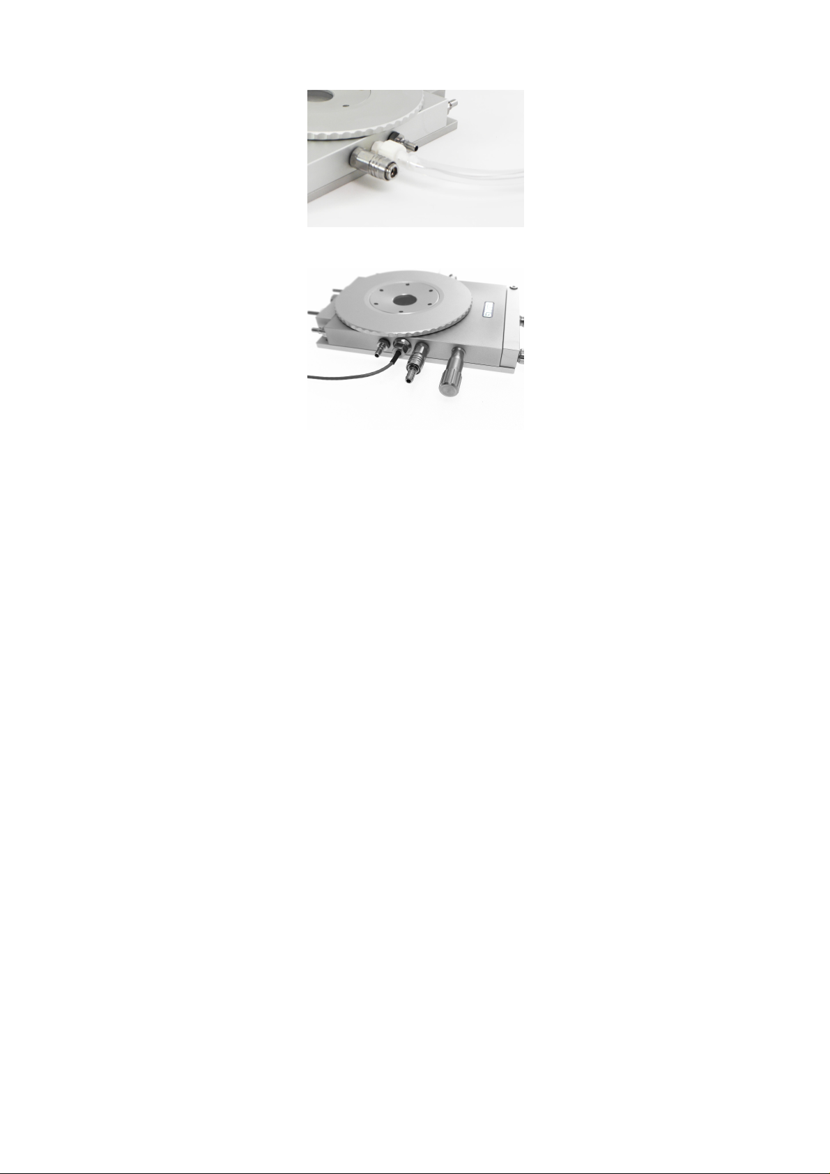
4. Connect the humidity tube from the front of the RH95 to the port on the Linkam stage, as shown:
5. Insert the gas valve insert into the gas valve on the opposing side of the stage to the humidity feed.
6. You are now ready to control the humidity of your Linkam stage.
v1.1.1
© 2017 Linkam Scientific Instruments Ltd.
11
Page 12
Using the RH9 5 Contr o ller
This section describes the operation of the RH95 control unit.
Filling the water bottle
Before the RH95 can control the humidity of your sample chamber, the water bottle must be filled. It is important that only distilled water is used in
the Humidity Generator.
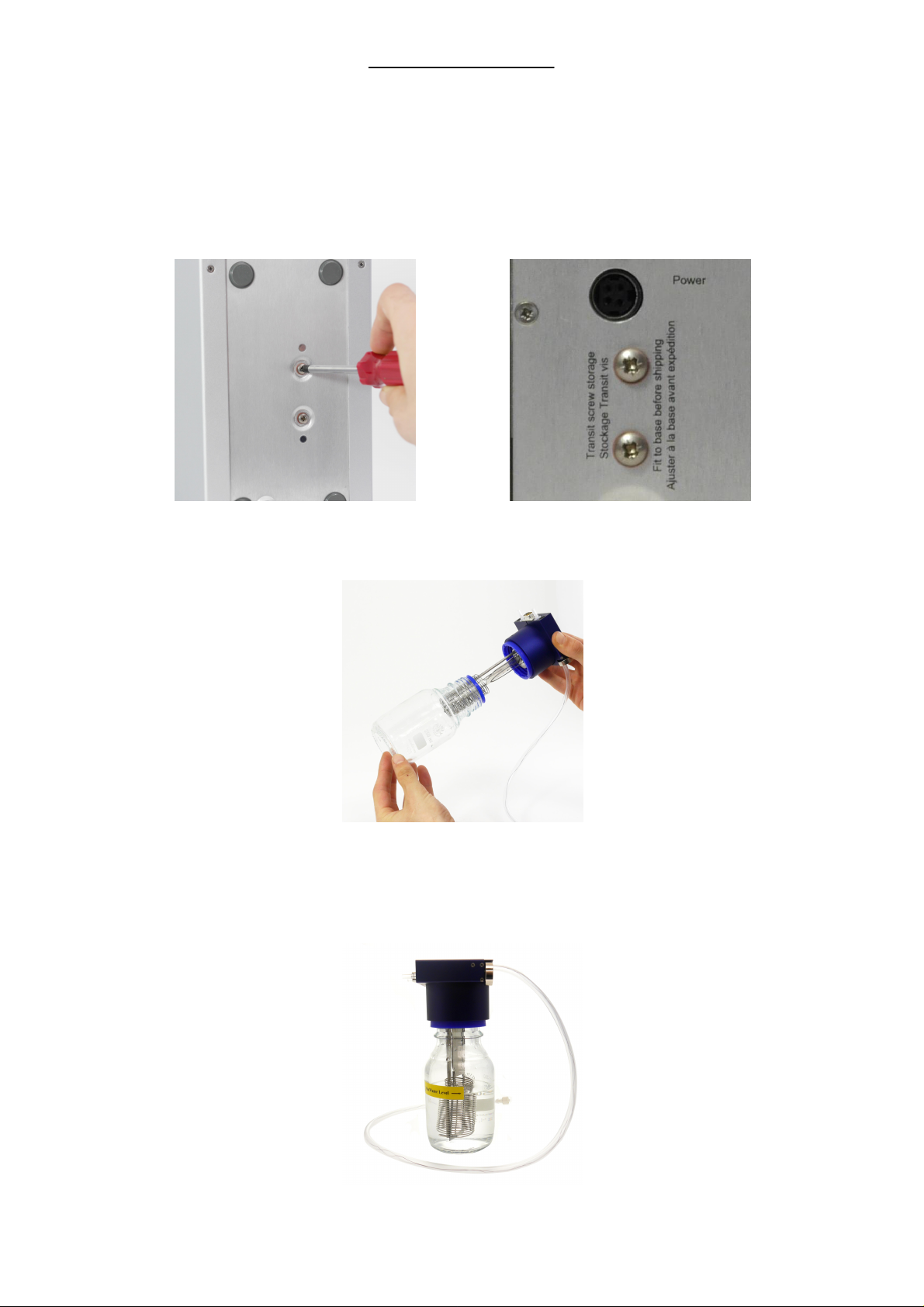
Step 1:
Make sure the controller is powered down and that the transit screws have been removed from the base of the unit. Store these screws in the
provided holes on the back panel of the unit.
Step 2:
Unscrew the bottle lid assembly and remove from the bottle, being careful not to damage the heating element.
Step 3:
Half fill the bottle to the level indicated and carefully re-attach the lid assembly. Do not fill the bottle past the maximum level indicator.
12
v1.1.1
© 2017 Linkam Scientific Instruments Ltd.
Page 13
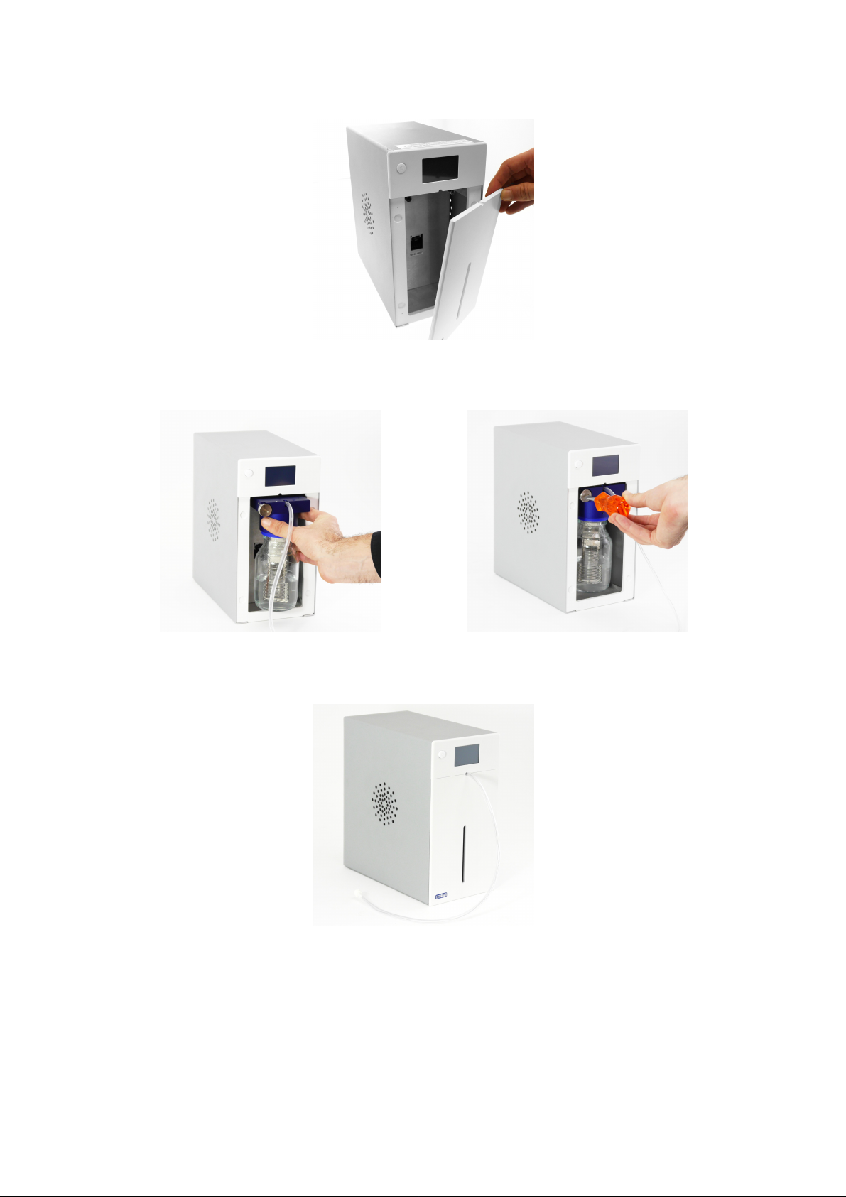
Step 4:
Remove the magnetic front panel of the RH95
Step 5:
Slide the bottle into the RH95 and tighten the locking screw until it is just tight. Do not over tighten the screw.
Step 6:
Replace the magnetic front panel of the RH95
Important Note: Before shipping the RH95, the water bottle should be removed from the unit, drained and placed into the space provided in the
packaging. The RH95 should not be shipped with the water bottle fitted.
v1.1.1
© 2017 Linkam Scientific Instruments Ltd.
13
Page 14
Desiccant conditioning
When the RH95 has not been used in some time, the desiccant in the controller will need drying out before use. It is advised to perform this
procedure when the goods are initially received.
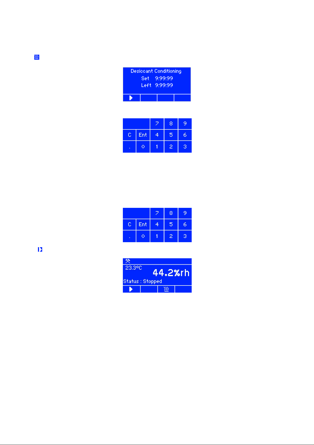
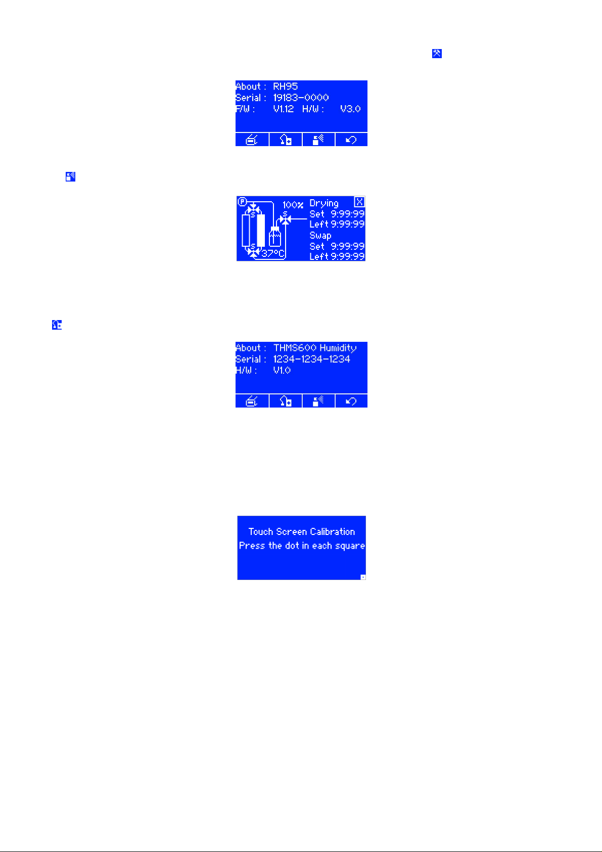
Tap the button and the following screen will appear:
tap the 'set' time display and a keypad screen will appear:
Enter the time required in hours, minutes and seconds and press enter, then push the start button to begin the conditioning.
NOTE: The suggested drying time is 1:00:00 hour.
Setting the humidity level
Tap on the humidity value on the LCD display of the RH95 controller. This will bring up a number pad. Enter a humidity value of between 10-90% and
press Ent. Press C to clear the last digit.
Press the (start) button to begin controlling the humidity in your chamber.
14
v1.1.1
© 2017 Linkam Scientific Instruments Ltd.
Page 15
RH95 settings and configuration
To check the serial numbers and firmware information for the humidity controller and attached sensor, tap the button at the top of the screen,
and the following screen will appear:
RH95 status
Tap the button in the settings screen to see a graphical display of the current status of the RH95, as below:
Tap the 'X' button to return to the previous screen.
Humidity sensor details
The button accesses the humidity sensor information. This includes the chamber type it is designed for and the serial number of the sensor.
Touchscreen Calibration
If the touchscreen interface on the RH95 is not responding correctly to touch input, it may need to be re-calibrated. In order to do this, please follow
this procedure:
1. Power down the RH95 Controller.
2. Place a finger on the touchscreen and hold it there
3. While continuing to hold a finger on the screen, power the RH95 back on, you should see the below screen:
(you can now remove the finger from the screen)
4. Touch the blue dot in the centre of each small white square. Once all 4 corners have been touched the RH95 will start normally.
NOTE: Use a biro or stylus to complete this operation, touches with a finger may not be sufficiently accurate.
v1.1.1
© 2017 Linkam Scientific Instruments Ltd.
15
Page 16
Validating the humidity reading
If you have purchased an optional Rotronic calibration standard with your RH95 unit, you can use these to validate the humidity reading of your
RH95.
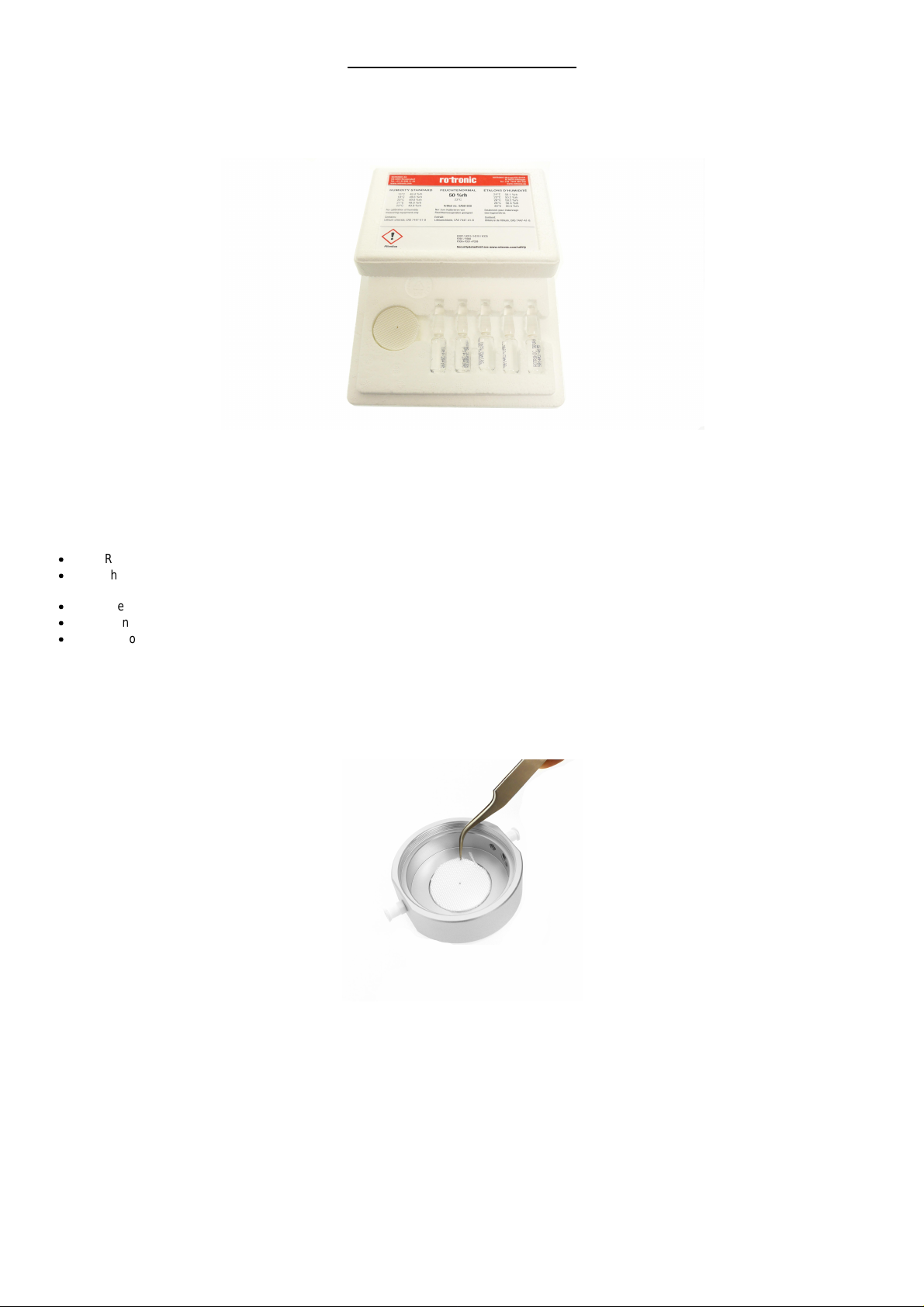
You should have received the following package:
This will contain some textile pads and five ampoules of calibration salts. The RH% will depend upon which kit was ordered. They are available in RH
values of 10%, 35%, 65% and 80%.
These standards consist of salts which will alter the humidity of a small enclosed space to a specific RH value, by either absorbing or releasing
moisture into the air. The humidity readings can be affected by several factors, so the environment must be controlled when using these validation
standards:
·
Room temperature must be 23°C +/-2°C.
·
The humidity standard must be at the same temperature as the humidity sensor. A 1 degree difference in temperature can cause an error of
up to 6% RH
·
There must be no draughts in the calibration room
·
Do not expose the calibration chamber to direct sunlight while in use
·
Do not expose the calibration salts to direct sunlight at any time.
Usage directions
Note: It is recommended that you wear safety goggles while performing this validation procedure.
1. Remove the lid of the supplied humidity chamber and place one of the textile pads in the recess.
Note: do not touch the textile pad with bare hands, as this can cause contamination and inaccurate readings. Wear sterile gloves, or use a clean
pair of pliers or tweezers to load the pad.
16
© 2017 Linkam Scientific Instruments Ltd.
v1.1.1
Page 17
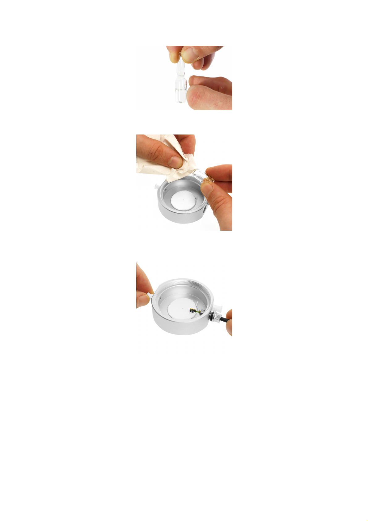
2. Hold the ampoule of the selected humidity standard at the neck and bring the entire contents into the further, lower part of the ampoule by
swinging or lightly tapping against the glass.
3. Break the ampoule at the marked place and empty it completely on the center of the textile pad while tapping it lightly to make sure all of
the liquid is soaked into the pad.
Note: wrap the top of the ampoule with tissue paper to contain any glass fragments.
4. Screw the humidity sensor into the chamber.
Note: Be careful during this step to make sure the RH sensor does not come into contact with the soaked pad. The salts will damage the sensor if it
comes into contact with them.
v1.1.1
© 2017 Linkam Scientific Instruments Ltd.
17
Page 18
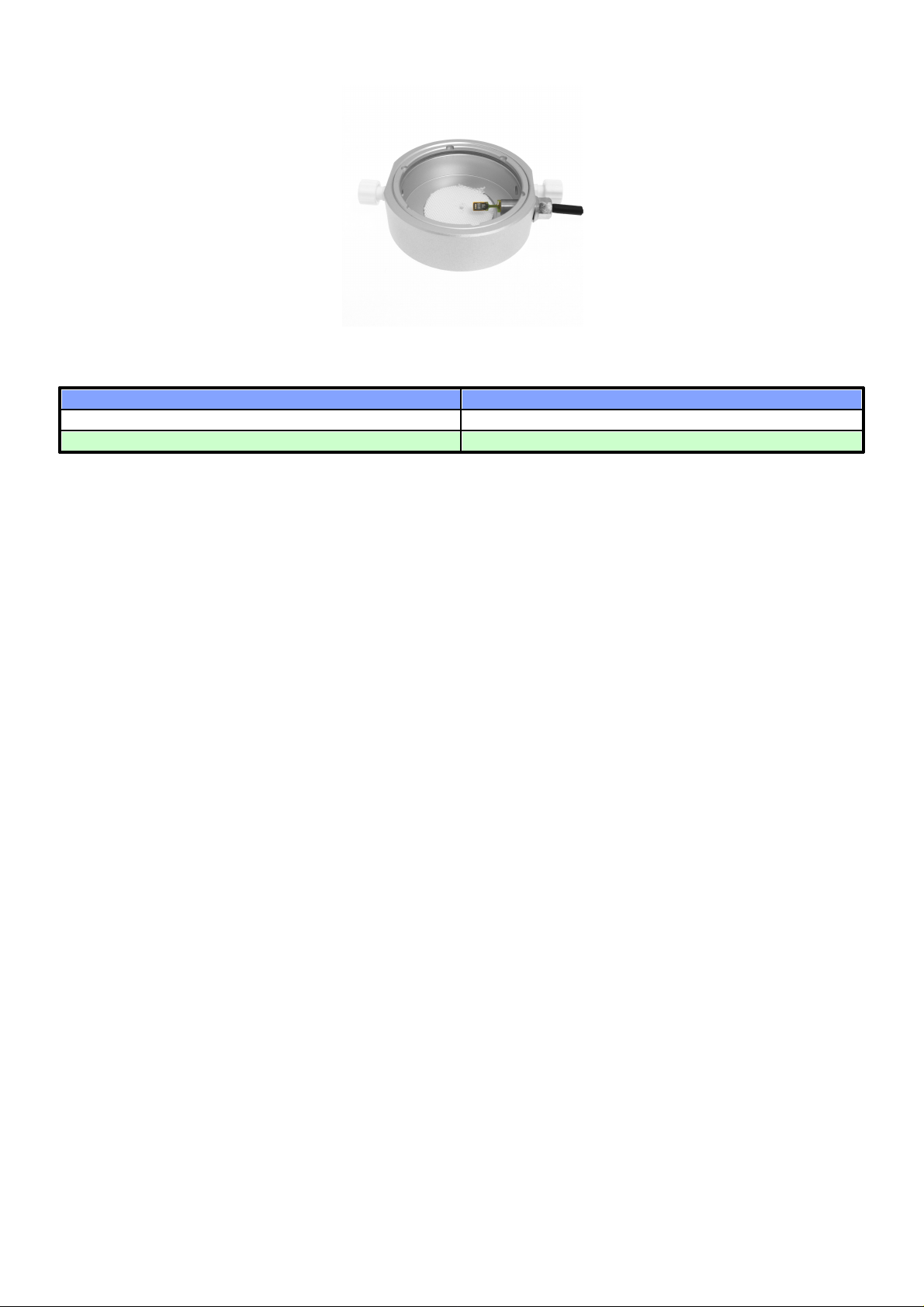
5. Replace the lid of the humidity chamber and place the caps on the white plastic air ports.
Time to reach equilibrium
RH% of humidity standard
45 minutes
10%, 35%, 65%
60 minutes
80%
6. Allow the chamber to reach humidity equilibrium (see table below) and switch the RH95 unit on. You can now compare the humidity reading
of the RH95 with the expected humidity value of the calibration standard used to validate the accuracy of the RH95.
Note: After every calibration the textile pad must be renewed and the chamber washed out with water and well dried. Thoroughly wash your hands
to remove any traces of the calibration salts.
18
v1.1.1
© 2017 Linkam Scientific Instruments Ltd.
Page 19

Declara t ion of Conform ity
Manufacturers Name: Linkam Scientific Instruments Ltd
Manufacturers Address:
8 Epsom Downs Metro Centre
Waterfield
Tadworth
Surrey
KT20 5LR
UK
Declares that the products as originally delivered:
Product Name: RH95 Controller
has been found to comply with the following applicable European Directives, and carries the CE marking accordingly:
EMC Directive 2014/30/EU using product standard EN 61326-1:2013
Low Voltage Directive 2014/35/EU using product standard EN 61010-1:2010
RoHS 2 Directive 2011/65/EU
and als o carries the additional certification:
EMC: FCC CFR 47 Part 15B:2014
Safety: IEC 61010-1:2010/EN 61010-1:2010/UL 60950-1:2012/CAN/ CSA no. 61010-1-12
Date: 14th April 2016
R&D Manager: Peter Grocutt
v1.1.1
© 2017 Linkam Scientific Instruments Ltd.
19
Page 20

Technical Specifications
RH95 Controller
Dimensions: 250 x 270 x 140 (mm)
Weight: 4.5Kg (excluding cables and power supply)
Operating Environment: 5~40°C, 80% relative humidity at 31°C decreasing linearly to 50% at 40°C (without condensation)
Supply voltage: 24Vdc
Max current: 3A
Display Resolution: 128 X 64 pixels
Display Size: 2.3 inch
User Interface: Touch screen
RH Sensor: Digital capacitive sensor
RH Range: 10 to 90%
RH Resolution: 0.1% resolution
RH Accuracy: 1.8%
RH Stability: 0.5%
Set Point Resolution: 0.1%
USB Interface
Micro USB Type B connector: Currently only used for firmware updates.
Power Supply
Supply Voltage: 24Vdc
Minimum Supply Current: 3A
Connector: 4 pin Mini DIN
Note—only use an earth referenced power supply with this equipment
20
v1.1.1
© 2017 Linkam Scientific Instruments Ltd.
Page 21

v1.1.1
© 2017 Linkam Scientific Instruments Ltd.
21
Page 22

Linkam Scientifi c Instruments Ltd
Tel: +44(0)1737 363 476
Fax: +44(0)1 737 363 480
Email: [email protected]
Unit 8 Epsom Downs Metro Centre
Waterfield, Tadworth, Surrey, KT20 5LR, UK
www.linkam.co.uk
 Loading...