

LTC3555/LTC3555-X
High Effi ciency USB Power
Manager + Triple
Step-Down DC/DC
FEATURES
Power Manager
n
High Effi ciency Switching PowerPath™ Controller
with Bat-Track™ Adaptive Output Control
n
Programmable USB or Wall Current Limit
(100mA/500mA/1A)
n
Full Featured Li-Ion/Polymer Battery Charger
n
1.5A Maximum Charge Current
n
Internal 180mΩ Ideal Diode + External Ideal Diode
Controller Powers Load in Battery Mode
n
Low No-Load Quiescent Current when Powered from
BAT (<32µA)
DC/DCs
n
Triple High Effi ciency Step-Down DC/DCs
(1A/400mA/400mA I
n
All Regulators Operate at 2.25MHz
n
Dynamic Voltage Scaling on Two Outputs
n
I2C or Independent Enable, V
n
Low No-Load Quiescent Current: 20µA
n
28-Pin (4mm × 5mm × 0.75mm) QFN Package
OUT
)
Controls
OUT
APPLICATIONS
n
HDD-Based MP3 Players, PDAs, GPS, PMPs
n
Portable Medical Products
n
Handheld Instrumentation
n
Other USB-Based Handheld Products
DESCRIPTION
The LTC®3555 family are highly integrated USB compatible power management and battery charger ICs for
Li-Ion/Polymer battery applications. They include a high
effi ciency current limited switching PowerPath manager
with automatic load prioritization, a battery charger, an ideal
diode and three general purpose synchronous step-down
switching regulators.
The LTC3555 family limits input current to either 100mA
or 500mA for USB applications or 1A for adapter-powered
applications. Unlike linear chargers, the LTC3555 family’s
switching architecture transmits nearly all of the power available from the USB port to the load with minimal loss and
heat which eases thermal constraints in small spaces.
Two of the three general purpose switching regulators can
provide up to 400mA and the third can deliver 1A. The
entire product can be controlled via I
LTC3555-1/LTC3555-3 versions offer “instant-on” power
delivery to the portable product even with a very low battery
voltage. The LTC3555-3 version also has a reduced charger
fl oat voltage of 4.100V for battery safety and longevity.
The LTC3555 family is available in the low profi le 28-pin
(4mm × 5mm × 0.75mm) QFN surface mount package.
L, LT, LTC and LTM are registered trademarks of Linear Technology Corporation. PowerPath
and Bat-Track are trademarks of Linear Technology Corporation. All other trademarks are the
property of their respective owners. Protected by U.S. Patents, including 6522118 and 6404251.
2
C or simple I/O. The
TYPICAL APPLICATION
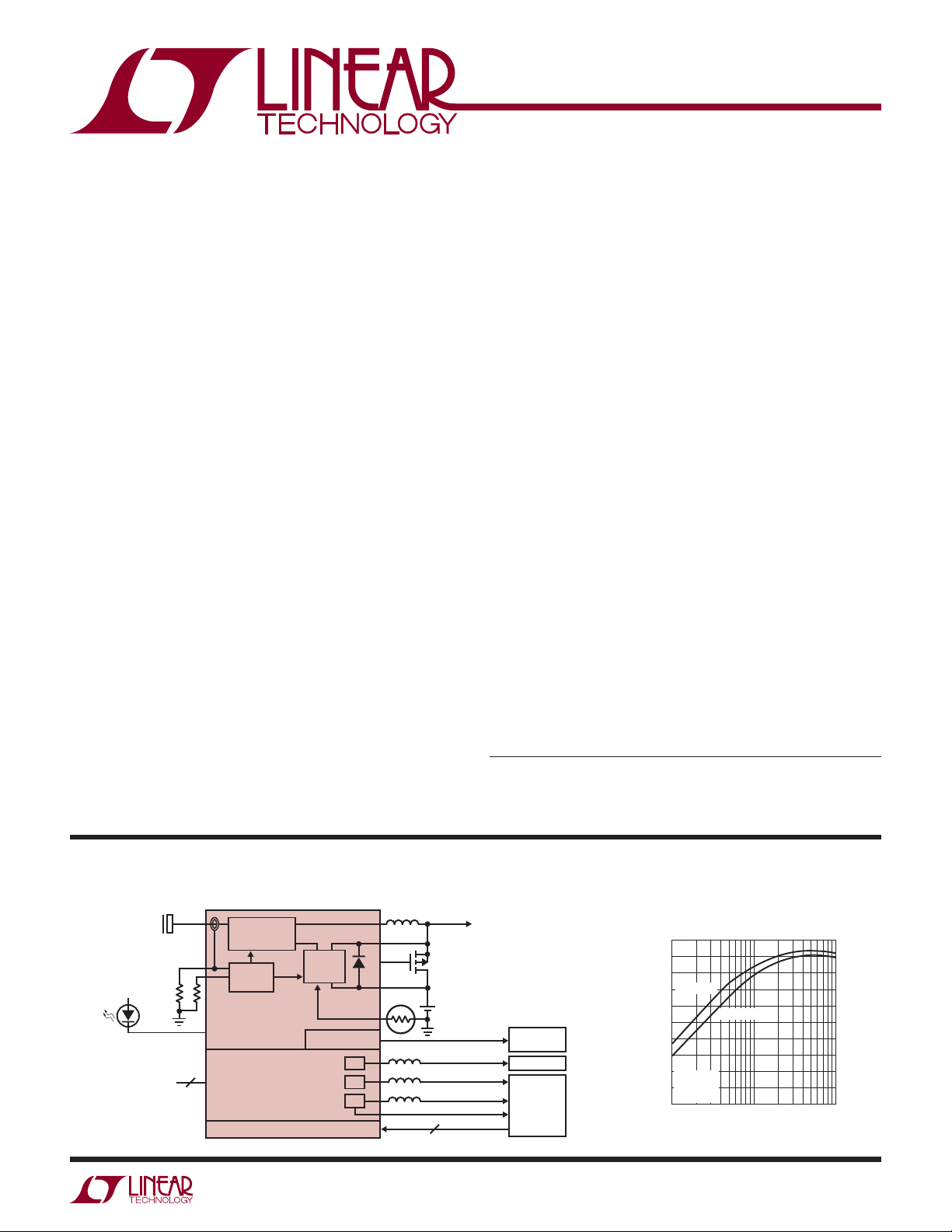
High Effi ciency PowerPath Manager and Triple Step-Down Regulator
USB/WALL
4.35V TO 5.5V
CHARGE
ENABLE
CONTROLS
5
USB COMPLIANT
STEP-DOWN
REGULATOR
CURRENT
CONTROL
LTC3555/LTC3555-X
HIGH EFFICIENCY
STEP-DOWN
SWITCHING
REGULATORS
2
I
TRIPLE
C PORT
CC/CV
BATTERY
CHARGER
ALWAYS ON LDO
0V
1
2
3
OPTIONAL
+
T
0.8V TO 3.6V/400mA
0.8V TO 3.6V/400mA
0.8V TO 3.6V/1A
RST
2
Li-Ion
TO OTHER
LOADS
3.3V/25mA
RTC/LOW
POWER LOGIC
MEMORY
I/O
CORE
µPROCESSOR
2
C
I
3555 TA01
Switching Regulator Effi ciency to
System Load (P
100
90
80
BAT = 4.2V
70
60
50
40
EFFICIENCY (%)
30
20
V
= 5V
BUS
= 0mA
I
10
BAT
10x MODE
0
0.01
OUT/PBUS
BAT = 3.3V
0.1 1
I
(A)
OUT
)
3555 TA01b
3555fd
1
LTC3555/LTC3555-X
ABSOLUTE MAXIMUM RATINGS
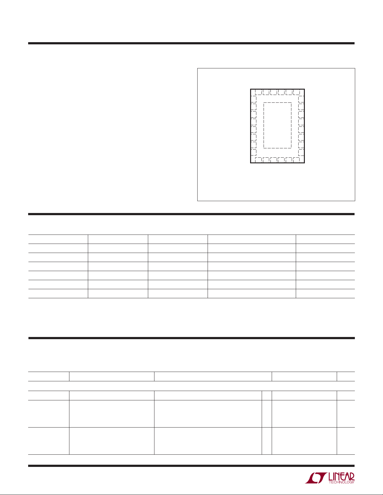
PIN CONFIGURATION
(Notes 1, 2, 3)
V
(Transient) t < 1ms,
BUS
Duty Cycle < 1% .......................................... –0.3V to 7V
, V
, V
, V
V
IN1
IN2
IN3
(Static), DVCC,
BUS
FB1, FB2, FB3, NTC, BAT, EN1, EN2, EN3,
, I
I
LIM0
I
CLPROG
I
RST3
I
PROG
I
LDO3V3
I
SW1
, I
I
SW
, SCL, SDA, RST3, CHRG ............ –0.3V to 6V
LIM1
....................................................................3mA
, I
............................................................50mA
CHRG
........................................................................2mA
...................................................................30mA
, I
............................................................600mA
SW2
, I
, I
SW3
BAT
...................................................2A
VOUT
Junction Temperature ........................................... 125°C
Operating Temperature Range (Note 2).... –40°C to 85°C
Storage Temperature Range ................... –65°C to 125°C
LDO3V3
CLPROG
NTC
FB2
V
IN2
SW2
EN2
DV
CC
28-LEAD (4mm × 5mm) PLASTIC QFN
EXPOSED PAD (PIN 29) IS GND, MUST BE SOLDERED TO PCB
TOP VIEW
LIM1ILIM0
I
SW
28 27 26 25 24
1
2
3
4
5
6
7
8
T
JMAX
29
9 10
11 12 13
IN3
SCL
SDA
V
UFD PACKAGE
= 125°C, θJA = 37°C/W
BUSVOUT
V
EN3
SW3
BAT
23
22
GATE
21
CHRG
20
PROG
19
FB1
18
V
IN1
17
SW1
16
EN1
15
RST3
14
FB3
ORDER INFORMATION
LEAD FREE FINISH TAPE AND REEL PART MARKING* PACKAGE DESCRIPTION TEMPERATURE RANGE
LTC3555EUFD#PBF LTC3555EUFD#TRPBF 3555 28-Lead (4mm x 5mm) Plastic QFN –40°C to 85°C
LTC3555IUFD#PBF LTC3555IUFD#TRPBF 3555 28-Lead (4mm x 5mm) Plastic QFN –40°C to 85°C
LTC3555EUFD-1#PBF LTC3555EUFD-1#TRPBF 35551 28-Lead (4mm x 5mm) Plastic QFN –40°C to 85°C
LTC3555IUFD-1#PBF LTC3555IUFD-1#TRPBF 35551 28-Lead (4mm x 5mm) Plastic QFN –40°C to 85°C
LTC3555EUFD-3#PBF LTC3555EUFD-3#TRPBF 35553 28-Lead (4mm x 5mm) Plastic QFN –40°C to 85°C
LTC3555IUFD-3#PBF LTC3555IUFD-3#TRPBF 35553 28-Lead (4mm x 5mm) Plastic QFN –40°C to 85°C
Consult LTC Marketing for parts specifi ed with wider operating temperature ranges. *The temperature grade is identifi ed by a label on the shipping container.
Consult LTC Marketing for information on non-standard lead based fi nish parts.
For more information on lead free part marking, go to: http://www.linear.com/leadfree/
For more information on tape and reel specifi cations, go to: http://www.linear.com/tapeandreel/
ELECTRICAL CHARACTERISTICS
The l denotes the specifi cations which apply over the full operating
temperature range, otherwise specifi cations are at TA = 25°C. V
= 5V, BAT = 3.8V, DVCC = 3.3V, R
BUS
PROG
= 1k, R
CLPROG
= 3k,
unless otherwise noted.
SYMBOL PARAMETER CONDITIONS MIN TYP MAX UNITS
PowerPath Switching Regulator
V
BUS
I
BUSLIM
I
VBUSQ
Input Supply Voltage 4.35 5.5 V
Total Input Current 1x Mode, V
V
Quiescent Current 1x Mode, I
BUS
5x Mode, V
10x Mode, V
Suspend Mode, V
5x Mode, I
10x Mode, I
Suspend Mode, I
OUT
OUT
OUT
OUT
OUT
= BAT
= BAT
OUT
= 0mA
= 0mA
= 0mA
= BAT
OUT
OUT
= BAT
= 0mA
l
87
l
436
l
800
l
0.31
95
460
860
0.38
7
15
15
0.044
100
500
1000
0.50
mA
mA
mA
mA
mA
mA
mA
mA
3555fd
2
LTC3555/LTC3555-X
ELECTRICAL CHARACTERISTICS
The l denotes the specifi cations which apply over the full operating
temperature range, otherwise specifi cations are at T
= 25°C. V
A
unless otherwise noted.
SYMBOL PARAMETER CONDITIONS MIN TYP MAX UNITS
h
CLPROG
(Note 4)
I
OUT(POWERPATH)VOUT
V
CLPROG
V
UVLO_VBUS
V
UVLO_VBUS-BAT
V
OUT
f
OSC
R
PMOS_POWERPATH
R
NMOS_POWERPATH
I
PEAK_POWERPATH
Battery Charger
V
FLOAT
I
CHG
I
BAT
V
PROG
V
PROG_TRKL
V
C/10
h
PROG
I
TRKL
V
TRKL
ΔV
TRKL
ΔV
RECHRG
t
TERM
t
BADBAT
h
C/10
Ratio of Measured V
CLPROG Program Current
Current to
BUS
1x Mode
5x Mode
10x Mode
Suspend Mode
Current Available Before
Loading BAT
1x Mode, BAT = 3.3V
5x Mode, BAT = 3.3V
10x Mode, BAT = 3.3V
Suspend Mode
CLPROG Servo Voltage in Current
Limit
V
Undervoltage Lockout Rising Threshold
BUS
1x, 5x, 10x Modes
Suspend Mode
Falling Threshold 3.95
V
to BAT Differential Undervoltage
BUS
Lockout
V
Voltage 1x, 5x, 10x Modes, 0V < BAT < 4.2V,
OUT
Rising Threshold
Falling Threshold
I
= 0mA, Battery Charger Off
OUT
USB Suspend Mode, I
Switching Frequency 1.8 2.25 2.7 MHz
PMOS On Resistance 0.18
NMOS On Resistance 0.30
Peak Switch Current Limit 1x, 5x Modes
10x
BAT Regulated Output Voltage LTC3555/LTC3555-1
LTC3555/LTC3555-1
LTC3555-3
LTC3555-3
Constant Current Mode Charge
Current
Battery Drain Current V
R
R
V
PROG
PROG
BUS
BUS
= 1k
= 5k
> V
= 0V, I
LTC3555
LTC3555-1/LTC3555-3
PROG Pin Servo Voltage 1.000 V
PROG Pin Servo Voltage in Trickle
BAT < V
Charge
C/10 Threshold Voltage at PROG 100 mV
Ratio of I
to PROG Pin Current 1022 mA/mA
BAT
Trickle Charge Current BAT < V
Trickle Charge Threshold Voltage BAT Rising 2.7 2.85 3.0 V
Trickle Charge Hysteresis Voltage 135 mV
Recharge Battery Threshold Voltage Threshold Voltage Relative to V
Safety Timer Termination Timer Starts when BAT = V
Bad Battery Termination Time BAT < V
End of Charge Indication Current Ratio (Note 5) 0.088 0.1 0.112 mA/mA
= 5V, BAT = 3.8V, DVCC = 3.3V, R
BUS
= 250µA 4.5 4.6 4.7 V
VOUT
, Battery Charger Off, I
UVLO
= 0µA (Ideal Diode Mode)
VOUT
TRKL
TRKL
FLOAT
FLOAT
TRKL
VOUT
= 0µA
PROG
= 1k, R
CLPROG
= 3k,
224
1133
2140
11.3
135
672
1251
0.32
1.188
100
4.30
4.35 V
4.00
200
50
3.4 BAT + 0.3 4.7 V
2
3
4.179
l
4.165
4.079
l
4.065
980
185
4.200
4.200
4.100
4.100
1022
204
2 3.5
27
32
4.221
4.235
4.121
4.135
1065
223
5
38
44
0.100 V
100 mA
–75 –100 –125 mV
3.3 4 5 Hour
0.42 0.5 0.63 Hour
mA/mA
mA/mA
mA/mA
mA/mA
mA
mA
mA
mA
mV
mV
mV
mA
mA
µA
µA
µA
V
V
A
A
V
V
V
V
3555fd
3
LTC3555/LTC3555-X
ELECTRICAL CHARACTERISTICS
The l denotes the specifi cations which apply over the full operating
temperature range, otherwise specifi cations are at T
= 25°C. V
A
unless otherwise noted.
SYMBOL PARAMETER CONDITIONS MIN TYP MAX UNITS
V
CHRG
I
CHRG
R
ON_CHG
T
LIM
NTC
V
COLD
V
HOT
V
DIS
I
NTC
Ideal Diode
V
FWD
R
DROPOUT
I
MAX_DIODE
Always On 3.3V LDO Supply
V
LDO3V3
R
CL_LDO3V3
R
OL_LDO3V3
Logic (I
LIM0
V
IL
V
IH
I
PD1
2
C Port
I
DV
CC
I
DVCC
V
DVCC_UVLO
ADDRESS I
, SDA, SCL Input High Threshold 70 %DV
V
IH
VIL, SDA, SCL Input Low Threshold 30 %DV
I
SDA, SCL Pull-Down Current 2µA
PD2
V
OL
f
SCL
t
BUF
t
HD_STA
t
SU_STA
CHRG Pin Output Low Voltage I
CHRG Pin Leakage Current V
= 5mA 65 100 mV
CHRG
= 5V 1 µA
CHRG
Battery Charger Power FET On
Resistance (Between V
and BAT)
OUT
Junction Temperature in Constant
Temperature Mode
Cold Temperature Fault Threshold
Voltage
Hot Temperature Fault Threshold
Voltage
Rising Threshold
Hysteresis
Falling Threshold
Hysteresis
NTC Disable Threshold Voltage Falling Threshold
Hysteresis
NTC Leakage Current V
Forward Voltage V
Internal Diode On Resistance, Dropout V
= V
NTC
= 0V, I
BUS
I
= 10mA
VOUT
= 0V 0.18
BUS
Internal Diode Current Limit 1.6 A
Regulated Output Voltage 0mA < I
Closed-Loop Output Resistance 4
Dropout Output Resistance 23
, I
, EN1, EN2, EN3)
LIM1
Logic Low Input Voltage 0.4 V
Logic High Input Voltage 1.2 V
I
, I
LIM0
, EN1, EN2, EN3
LIM1
Pull-Down Currents
Input Supply Voltage 1.6 5.5 V
DVCC Current SCL/SDA = 0kHz 0.5 µA
DVCC UVLO 1.0 V
2
C Address 0001 001[0]
Digital Output Low (SDA) I
= 3mA 0.4 V
PULLUP
Clock Operating Frequency 400 kHz
Bus Free Time Between Stop and Start
Condition
Hold Time After (Repeated) Start
Condition
Repeated Start Condition Setup Time 0.6 µs
= 5V, BAT = 3.8V, DVCC = 3.3V, R
BUS
PROG
= 1k, R
CLPROG
= 3k,
0.18
110 °C
75.0 76.5
78.0 %V
1.5
33.4 34.9
36.4 %V
1.5
0.7 1.7
2.7 %V
50
= 5V –50 50 nA
BUS
VOUT
= 10mA
2
15
< 25mA 3.1 3.3 3.5 V
LDO3V3
2µA
1.3 µs
0.6 µs
%V
%V
BUS
BUS
BUS
BUS
BUS
mV
mV
mV
CC
CC
3555fd
4
LTC3555/LTC3555-X
ELECTRICAL CHARACTERISTICS
The l denotes the specifi cations which apply over the full operating
temperature range, otherwise specifi cations are at T
= 25°C. V
A
unless otherwise noted.
SYMBOL PARAMETER CONDITIONS MIN TYP MAX UNITS
t
SU_STD
t
HD_DAT(OUT)
t
HD_DAT(IN)
t
SU_DAT
t
LOW
t
HIGH
t
f
t
r
t
SP
General Purpose Switching Regulators 1, 2 and 3
V
IN1,2,3
V
OUTUVLO
f
OSC
I
FB1,2,3
D
1,2,3
R
SW1,2,3_PD
General Purpose Switching Regulator 1
I
VIN1
I
LIMSW1
I
OUT1
V
FB1
R
P1
R
N1
R
LDO_CL1
R
LDO_OL1
General Purpose Switching Regulator 2
I
VIN2
I
LIMSW2
I
OUT2
Stop Condition Time 0.6 µs
Data Hold Time 225 ns
Input Data Hold Time 0 900 ns
Data Setup Time 100 ns
Clock Low Period 1.3 µs
Clock High Period 0.6 µs
Clock Data Fall Time 20 300 ns
Clock Data Rise Time 20 300 ns
Spike Suppression Time 50 ns
Input Supply Voltage 2.7 5.5 V
V
OUT
V
OUT
UVLO—V
UVLO—V
OUT
OUT
Falling
Rising
Connected to V
V
IN1,2,3
Impedance. Switching Regulators are Disabled in
UVLO
Oscillator Frequency 1.8 2.25 2.7 MHz
FBx Input Current V
= 0.85V –50 50 nA
FB1,2,3
Maximum Duty Cycle 100 %
SWx Pull-Down in Shutdown 10 k
Pulse Skip Mode Input Current
Burst Mode Input Current
Forced Burst Mode
®
Input Current
LDO Mode Input Current
Shutdown Input Current
= 0µA (Note 6)
I
OUT1
I
= 0µA (Note 6)
OUT1
I
= 0µA (Note 6)
OUT1
I
= 0µA (Note 6)
OUT1
I
= 0µA, FB1 = 0V
OUT1
PMOS Switch Current Limit Pulse Skip/Burst Mode Operation 600 800 1100 mA
Available Output Current Pulse Skip/Burst Mode Operation (Note 7)
Forced Burst Mode Operation (Note 7)
LDO Mode (Note 7)
V
Servo Voltage (Note 8)
FB1
PMOS R
DS(ON)
NMOS R
DS(ON)
LDO Mode Closed-Loop R
LDO Mode Open-Loop R
Pulse Skip Mode Input Current
Burst Mode Input Current
Forced Burst Mode Input Current
LDO Mode Input Current
Shutdown Input Current
OUT
OUT
(Note 9) 2.5
I
= 0µA (Note 6)
OUT2
I
= 0µA (Note 6)
OUT2
I
= 0µA (Note 6)
OUT2
I
= 0µA (Note 6)
OUT2
I
= 0µA, FB2 = 0V
OUT2
PMOS Switch Current Limit Pulse Skip/Burst Mode Operation 600 800 1100 mA
Available Output Current Pulse Skip/Burst Mode Operation (Note 7)
Forced Burst Mode Operation (Note 7)
LDO Mode (Note 7)
= 5V, BAT = 3.8V, DVCC = 3.3V, R
BUS
Through Low
OUT
PROG
= 1k, R
CLPROG
= 3k,
2.5 2.6
2.8 2.9
225
35
20
20
60
35
35
1
400
60
50
l
0.78 0.80 0.82 V
0.6
0.7
0.25
225
35
20
20
60
35
35
1
400
60
50
µA
µA
µA
µA
µA
mA
mA
mA
µA
µA
µA
µA
µA
mA
mA
mA
V
V
Burst Mode is a registered trademark of Linear Technology Corporation.
3555fd
5

LTC3555/LTC3555-X
ELECTRICAL CHARACTERISTICS
The l denotes the specifi cations which apply over the full operating
temperature range, otherwise specifi cations are at T
unless otherwise noted.
SYMBOL PARAMETER CONDITIONS MIN TYP MAX UNITS
V
FBHIGH2
V
FBLOW2
V
LSB2
R
P2
NMOS R
R
N2
R
LDO_CL2
R
LDO_OL2
General Purpose Switching Regulator 3
I
VIN3
I
LIMSW3
I
OUT3
V
FBHIGH3
V
FBLOW3
V
LSB3
R
P3
R
N3
R
LDOCL3
R
LDOOL3
t
RST3
Maximum Servo Voltage Full Scale (1, 1, 1, 1) (Note 8)
Minimum Servo Voltage Zero Scale (0, 0, 0, 0) (Note 8) 0.405 0.425 0.445 V
V
Servo Voltage Step Size 25 mV
FB2
PMOS R
DS(ON)
DS(ON)
LDO Mode Closed-Loop R
LDO Mode Open-Loop R
OUT
OUT
Pulse Skip Mode Input Current
Burst Mode Input Current
Forced Burst Mode Input Current
LDO Mode Input Current
Shutdown Input Current
PMOS Switch Current Limit Pulse Skip/Burst Mode Operation 1500 2000 2800 mA
Available Output Current Pulse Skip/Burst Mode Operation (Note 7)
Maximum Servo Voltage Full Scale (1, 1, 1, 1) (Note 8)
Minimum Servo Voltage Zero Scale (0, 0, 0, 0) (Note 8) 0.405 0.425 0.445 V
VFB Servo Voltage Step Size 25 mV
PMOS R
DS(ON)
NMOS R
DS(ON)
LDO Mode Closed Loop R
LDO Mode Open Loop R
OUT
OUT
Power On Reset Time for Switching
Regulator
= 25°C. V
A
= 5V, BAT = 3.8V, DVCC = 3.3V, R
BUS
= 1k, R
PROG
l
0.78 0.80 0.82 V
CLPROG
= 3k,
0.6
0.7
0.25
(Note 9) 2.5
I
= 0µA (Note 6)
OUT3
I
= 0µA (Note 6)
OUT3
I
= 0µA (Note 6)
OUT3
I
= 0µA (Note 6)
OUT3
I
= 0µA, FB3 = 0V
OUT3
Forced Burst Mode Operation (Note 7)
LDO Mode (Note 7)
1000
150
50
l
0.78 0.80 0.82 V
225
35
20
20
60
35
35
1
mA
mA
mA
0.18
0.30
0.25
(Note 9) 2.5
V
Within 92% of Final Value to RST3 Hi-Z 230 ms
FB3
µA
µA
µA
µA
µA
Note 1: Stresses beyond those listed under Absolute Maximum Ratings
may cause permanent damage to the device. Exposure to any Absolute
Maximum Rating condition for extended periods may affect device
reliability and lifetime.
Note 2: The LTC3555E/LTC3555E-X are guaranteed to meet performance
specifi cations from 0°C to 85°C. Specifi cations over the – 40°C to 85°C
operating temperature range are assured by design, characterization and
correlation with statistical process controls. The LTC3555I/LTC3555I-X are
guaranteed to meet performance specifi cations over the full –40°C to 85°C
operating temperature range.
Note 3: The LTC3555/LTC3555-X include overtemperature protection that
is intended to protect the device during momentary overload conditions.
Junction temperature will exceed 125°C when overtemperature protection
is active. Continuous operation above the specifi ed maximum operating
junction temperature may impair device reliability.
6
Note 4: Total input current is the sum of quiescent current, I
VBUSQ
, and
measured current given by:
V
CLPROG/RCLPROG
Note 5: h
C/10
• (h
CLPROG
+1)
is expressed as a fraction of measured full charge current
with indicated PROG resistor.
Note 6: FBx above regulation such that regulator is in sleep. Specifi cation
does not include resistive divider current refl ected back to V
INx
.
Note 7: Guaranteed by design but not explicitly tested.
Note 8: Applies to pulse skip, Burst Mode operation and forced Burst
Mode operation only.
Note 9: Inductor series resistance adds to open-loop R
OUT
.
3555fd
TYPICAL PERFORMANCE CHARACTERISTICS
LTC3555/LTC3555-X
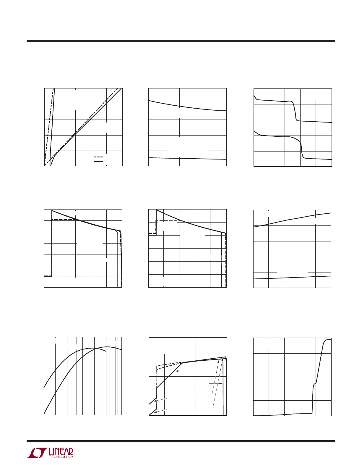
Ideal Diode V-I Characteristics
1.0
0.8
0.6
0.4
CURRENT (A)
0.2
INTERNAL IDEAL DIODE
WITH SUPPLEMENTAL
EXTERNAL VISHAY
Si2333 PMOS
0
0.04
0
0.08
FORWARD VOLTAGE (V)
USB Limited Battery Charge
Current vs Battery Voltage
700
600
500
400
300
200
CHARGE CURRENT (mA)
100
5x USB SETTING,
BATTERY CHARGER SET FOR 1A
0
2.7
LTC3555
LTC3555-1/
LTC3555-3
3.0 3.3 3.6 4.2
V
= 5V
BUS
R
PROG
R
CLPROG
BATTERY VOLTAGE (V)
INTERNAL IDEAL
DIODE ONLY
V
BUS
V
BUS
0.12
0.16
= 1k
= 3k
LTC3555-3
3.9
= 0V
= 5V
3555 G01
3555 G04
0.20
Ideal Diode Resistance
vs Battery Voltage
0.25
0.20
INTERNAL IDEAL
0.15
0.10
RESISTANCE (Ω)
0.05
0
2.7
DIODE
INTERNAL IDEAL DIODE
WITH SUPPLEMENTAL
EXTERNAL VISHAY
Si2333 PMOS
3.0
3.3
BATTERY VOLTAGE (V)
USB Limited Battery Charge
Current vs Battery Voltage
150
125
100
75
50
CHARGE CURRENT (mA)
25
1x USB SETTING,
BATTERY CHARGER SET FOR 1A
0
2.7
LTC3555
LTC3555-1/
LTC3555-3
3.0 3.3 3.6 3.9
V
BUS
R
PROG
R
CLPROG
BATTERY VOLTAGE (V)
3.6
= 5V
= 1k
= 3k
LTC3555-3
3.9
3555 G02
3555 G05
4.2
4.2
Output Voltage vs Output Current
(Battery Charger Disabled)
4.50
BAT = 4V
4.25
4.00
BAT = 3.4V
3.75
OUTPUT VOLTAGE (V)
3.50
3.25
200
0
OUTPUT CURRENT (mA)
400
600
Battery Drain Current
vs Battery Voltage
25
= 0µA
I
VOUT
BUS
V
= 5V
3.6
20
15
10
BATTERY CURRENT (µA)
5
0
2.7
V
(SUSPEND MODE)
3.0
3.3
BATTERY VOLTAGE (V)
BUS
V
= 5V
BUS
5x MODE
800
3555 G03
= 0V
3.9
3555 G06
1000
4.2
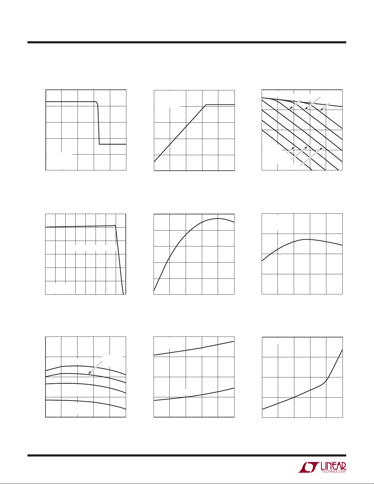
PowerPath Switching Regulator
Effi ciency vs Output Current
100
BAT = 3.8V
90
80
70
EFFICIENCY (%)
60
50
40
0.01
1x MODE
0.1 1
OUTPUT CURRENT (A)
5x, 10x MODE
3555 G07
Battery Charging Effi ciency vs
Battery Voltage with No External
Load (P
100
R
CLPROG
R
PROG
= 0mA
I
VOUT
90
80
EFFICIENCY (%)
70
60
2.7
BAT/PBUS
= 3k
= 1k
3.0
)
LTC3555-1/
LTC3555-3
LTC3555-3
1x CHARGING EFFICIENCY
5x CHARGING EFFICIENCY
3.6
3.3
BATTERY VOLTAGE (V)
3.9
3555 G08
50
40
30
20
QUIESCENT CURRENT (µA)
10
4.2
Current vs V
V
BUS
(Suspend)
BAT = 3.8V
I
VOUT
0
0
= 0mA
1
Voltage
BUS
3
2
BUS VOLTAGE (V)
4
5
3555 G09
3555fd
7
LTC3555/LTC3555-X
TYPICAL PERFORMANCE CHARACTERISTICS
Output Voltage vs Load Current in
Suspend
5.0
4.5
4.0
3.5
OUTPUT VOLTAGE (V)
3.0
V
= 5V
BUS
BAT = 3.3V
= 3k
R
CLPROG
2.5
0.1
0
LOAD CURRENT (mA)
0.2
0.3
Battery Charge Current vs
Temperature
600
500
400
300
200
CHARGE CURRENT (mA)
100
R
PROG
10x MODE
0
–40
–20 20
THERMAL REGULATION
= 2k
040
TEMPERATURE (°C)
60
V
Current vs Load Current in
BUS
Suspend
0.5
V
= 5V
BUS
BAT = 3.3V
= 3k
R
CLPROG
0.4
0.3
CURRENT (mA)
0.2
BUS
V
0.1
0.4
0.5
3555 G10
0
0.1
0
LOAD CURRENT (mA)
0.2
0.3
0.4
0.5
3555 G11
Normalized Battery Charger Float
Voltage vs Temperature
1.001
1.000
0.999
0.998
0.997
NORMALIZED FLOAT VOLTAGE
80
100
120
3555 G13
0.996
–40
–15
10
TEMPERATURE (°C)
35
60
85
3555 G14
3.3V LDO Output Voltage vs Load
3.4
3.2
3.0
OUTPUT VOLTAGE (V)
2.8
2.6
Current, V
BAT = 3.9V, 4.2V
BAT = 3V
BAT = 3.1V
BAT = 3.2V
0
= 0V
BUS
BAT = 3.4V
BAT = 3.3V
5
10
LOAD CURRENT (mA)
BAT = 3.5V
15
Low-Battery (Instant-On) Output
Voltage vs Temperature
3.68
BAT = 2.7V
= 100mA
I
VOUT
5x MODE
3.66
3.64
OUTPUT VOLTAGE (V)
3.62
3.60
–40
–15
10
TEMPERATURE (°C)
35
BAT = 3.6V
20
3555 G12
60
3555 G15
25
85
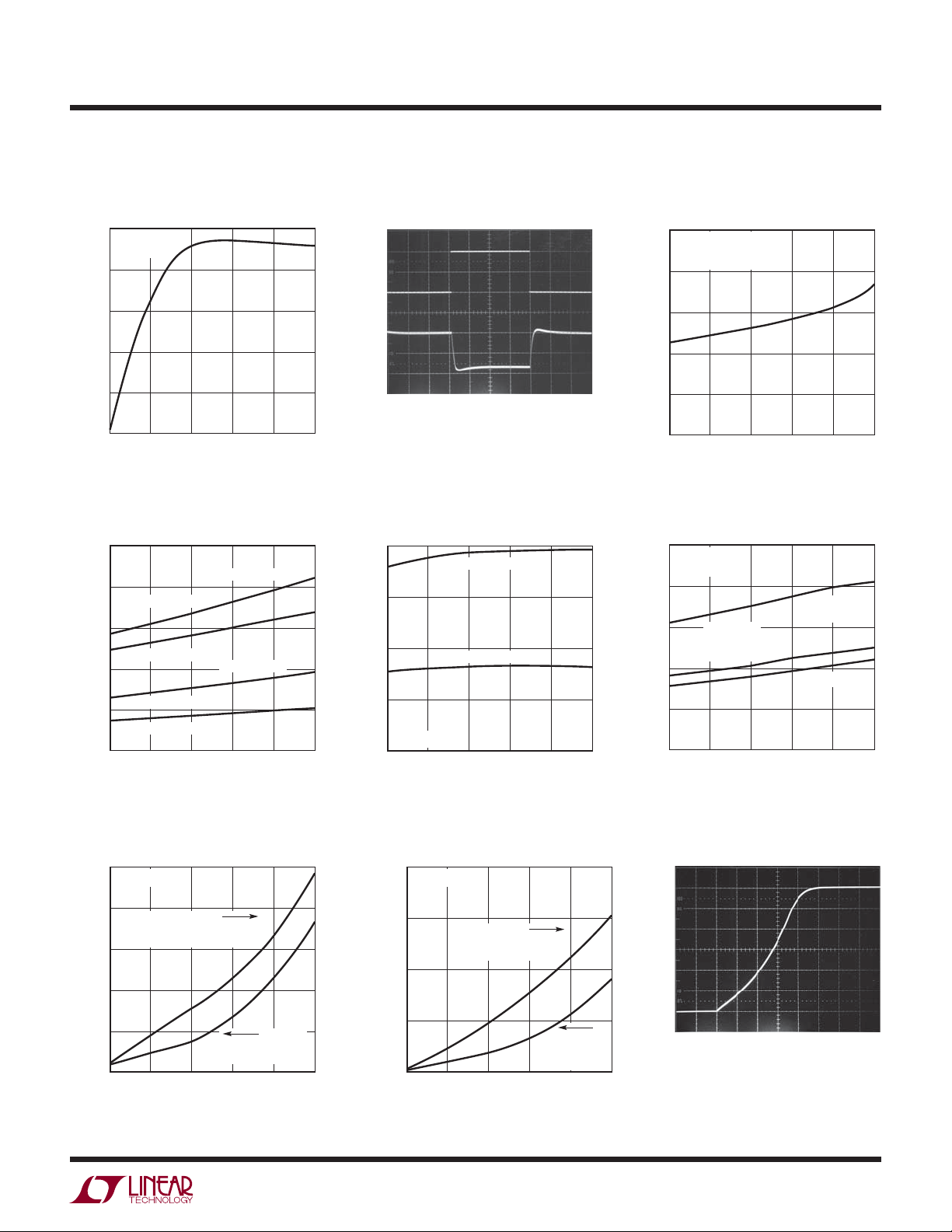
Oscillator Frequency vs
Temperature
2.6
2.4
2.2
FREQUENCY (MHz)
2.0
1.8
–40
–15
8
V
= 5V
BUS
BAT = 3V
= 0V
V
BUS
BAT = 2.7V
= 0V
V
BUS
35
10
TEMPERATURE (°C)
BAT = 3.6V
= 0V
V
BUS
60
3555 G16
15
12
QUIESCENT CURRENT (mA)
85
Quiescent Current vs
V
BUS
Temperature
V
= 5V
BUS
= 0µA
I
VOUT
9
6
3
–40
1x MODE
–15
TEMPERATURE (°C)
V
Quiescent Current in
BUS
Suspend vs Temperature
70
I
= 0µA
VOUT
5x MODE
35
60
10
85
3555 G17
60
50
40
QUIESCENT CURRENT (µA)
30
–40
–15
10
TEMPERATURE (°C)
35
60
85
3555 G18
3555fd
TYPICAL PERFORMANCE CHARACTERISTICS
LTC3555/LTC3555-X
RST3, CHRG Pin Current vs
Voltage (Pull-Down State)
100
V
= 5V
BUS
BAT = 3.8V
80
60
40
20
RST3, CHRG PIN CURRENT (mA)
0
1
0
RST3, CHRG PIN VOLTAGE (V)
R
for Switching Regulator
DS(ON)
3
2
Power Switches vs Temperature
1.0
0.8
0.6
0.4
ON-RESISTANCE (Ω)
0.2
0
–40
NMOS SWITCH
PMOS SWITCH
NMOS SWITCH
PMOS SWITCH
–15
REGULATORS 1, 2
REGULATOR 3
35
10
TEMPERATURE (°C)
3.3V LDO Step Response
(5mA to 15mA)
I
LDO3V3
5mA/DIV
0mA
V
LDO3V3
20mV/DIV
AC COUPLED
20µs/DIVBAT = 3.8V
4
5
3555 G19
3555 G20
Switching Regulator Current Limit
vs Temperature
2.0
REGULATOR 3
1.5
1.0
CURRENT LIMIT (A)
0.5
V
IN1,2,3
60
85
3555 G22
0
–40
REGULATORS 1, 2
= 3.8V
–15
10
TEMPERATURE (°C)
35
60
85
3555 G23
Battery Drain Current vs
Temperature
50
BAT = 3.8V
= 0V
V
BUS
BUCK REGULATORS OFF
40
30
20
BATTERY CURRENT (µA)
10
0
–40
–15
TEMPERATURE (°C)
35
10
Switching Regulator Low Power
Mode Quiescent Currents
50
V
= 3.8V
IN1,2,3
= 2.5V
V
OUT1,2,3
40
30
20
INPUT CURRENT (µA)
10
0
–40
FORCED
Burst Mode
OPERATION
–15
10
TEMPERATURE (°C)
35
60
Burst Mode
OPERATION
LDO MODE
60
85
3555 G21
85
3555 G24
Switching Regulators 1, 2 Pulse
Skip Mode Quiescent Currents
325
V
= 3.8V
IN1,2
300
V
= 2.5V
275
250
INPUT CURRENT (µA)
225
200
(CONSTANT FREQUENCY)
–15
–40
OUT1,2
V
OUT1,2
(PULSE SKIPPING)
35
10
TEMPERATURE (°C)
= 1.25V
60
3555 G25
1.95
1.90
INPUT CURRENT (mA)
1.85
1.80
1.75
1.70
85
Switching Regulator 3 Pulse Skip
Mode Quiescent Currents
400
V
= 2.5V
OUT3
350
V
= 3.5V
(CONSTANT FREQUENCY)
300
INPUT CURRENT (µA)
250
200
–40
–15
TEMPERATURE (°C)
IN3
35
10
V
= 3.8V
IN3
(PULSE
SKIPPING)
60
3555 G26
11
INPUT CURRENT (mA)
10
9
8
7
85
Switching Regulator Soft-Start
Waveform
500mV/DIV
OUT
V
50µs/DIV
3555 G27
3555fd
9
LTC3555/LTC3555-X
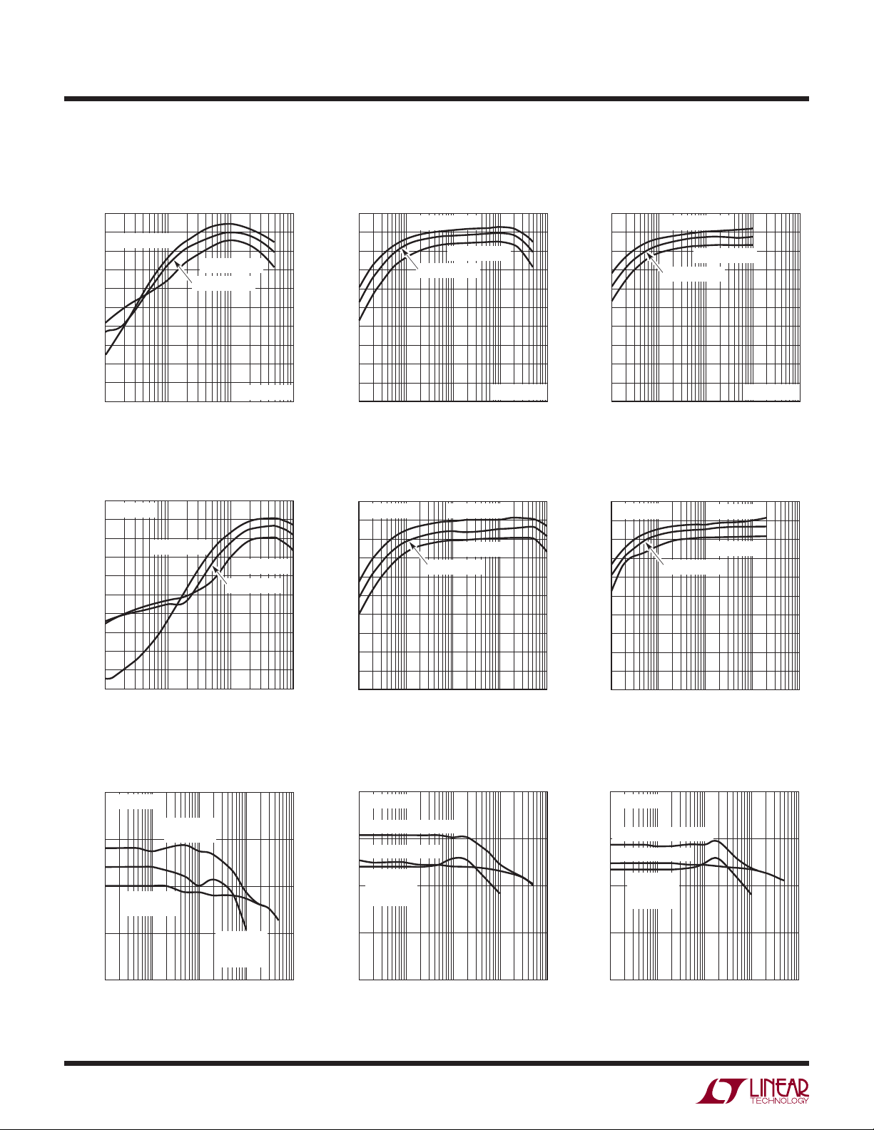
TYPICAL PERFORMANCE CHARACTERISTICS
Switching Regulators 1, 2
Pulse Skip Mode Effi ciency
100
90
V
= 2.5V
OUT1,2
80
70
60
50
40
EFFICIENCY (%)
30
20
10
0
1
10 100 1000
LOAD CURRENT (mA)
Switching Regulator 3
Pulse Skip Mode Effi ciency
100
V
= 3.8V
IN3
90
80
70
60
50
40
EFFICIENCY (%)
30
20
10
0
1
V
= 2.5V
OUT3
10 100 1000
LOAD CURRENT (mA)
V
OUT1,2
V
OUT1,2
= 1.2V
= 1.8V
V
V
OUT3
V
OUT3
IN1,2
= 3.8V
= 1.2V
= 1.8V
3555 G28
3555 G31
Switching Regulators 1, 2
Burst Mode Effi ciency
100
90
80
70
60
50
40
EFFICIENCY (%)
30
20
10
0
0.1 10 100 1000
V
= 2.5V
OUT1,2
V
OUT1,2
V
= 1.8V
OUT1,2
1
LOAD CURRENT (mA)
= 1.2V
V
IN1,2
Switching Regulator 3
Burst Mode Effi ciency
100
V
= 3.8V
IN3
90
80
70
60
50
40
EFFICIENCY (%)
30
20
10
0
0.1 10 100 1000
1
V
= 2.5V
OUT3
V
= 1.2V
OUT3
V
= 1.8V
OUT3
LOAD CURRENT (mA)
= 3.8V
3555 G29
3555 G32
Switching Regulators 1, 2
Forced Burst Mode Effi ciency
100
90
80
70
60
50
40
EFFICIENCY (%)
30
20
10
0
0.1 10 100 1000
V
= 2.5V
OUT1,2
V
= 1.2V
OUT1,2
V
= 1.8V
OUT1,2
1
LOAD CURRENT (mA)
V
IN1,2
Switching Regulator 3
Forced Burst Mode Effi ciency
100
V
= 3.8V
IN3
90
80
70
60
50
40
EFFICIENCY (%)
30
20
10
0
0.1 10 100 1000
V
1
LOAD CURRENT (mA)
OUT3
= 1.8V
V
V
OUT3
OUT3
= 2.5V
= 1.2V
= 3.8V
3555 G30
3555 G33
Switching Regulators 1, 2 Load
Regulation at V
1.230
V
= 3.8V
IN1,2
1.215
1.200
OUTPUT VOLTAGE (V)
1.185
1.170
PULSE SKIP
MODE
0.1 10 100 1000
OUT1,2
Burst Mode
OPERATION
Burst Mode
OPERATION
1
LOAD CURRENT (mA)
10
= 1.2V
FORCED
3555 G34
Switching Regulators 1, 2 Load
Regulation at V
1.845
V
= 3.8V
IN1,2
Burst Mode OPERATION
1.823
PULSE SKIP MODE
1.800
OUTPUT VOLTAGE (V)
1.778
1.755
FORCED
Burst Mode
OPERATION
0.1 10 100 1000
1
LOAD CURRENT (mA)
OUT1,2
= 1.8V
3555 G35
Switching Regulators 1, 2 Load
Regulation at V
2.56
V
= 3.8V
IN1,2
Burst Mode OPERATION
2.53
PULSE SKIP MODE
2.50
OUTPUT VOLTAGE (V)
2.47
2.44
FORCED
Burst Mode
OPERATION
0.1 10 100 1000
1
LOAD CURRENT (mA)
OUT1,2
= 2.5V
3555 G36
3555fd

PIN FUNCTIONS
LTC3555/LTC3555-X
LDO3V3 (Pin 1): 3.3V LDO Output Pin. This pin provides
a regulated always-on 3.3V supply voltage. LDO3V3
gets its power from V
. It may be used for light loads
OUT
such as a watchdog microprocessor or real time clock.
A 1µF capacitor is required from LDO3V3 to ground. If
the LDO3V3 output is not used it should be disabled by
connecting it to V
OUT
.
CLPROG (Pin 2): USB Current Limit Program and Monitor Pin. A resistor from CLPROG to ground determines
the upper limit of the current drawn from the V
A fraction of the V
current is sent to the CLPROG pin
BUS
BUS
pin.
when the synchronous switch of the PowerPath switching
regulator is on. The switching regulator delivers power until
the CLPROG pin reaches 1.188V. Several V
current limit
BUS
settings are available via user input which will typically
correspond to the 500mA and 100mA USB specifi cations.
A multi-layer ceramic averaging capacitor or R-C network
is required at CLPROG for fi ltering.
NTC (Pin 3): Input to the Thermistor Monitoring Circuits.
The NTC pin connects to a battery’s thermistor to determine if the battery is too hot or too cold to charge. If the
battery’s temperature is out of range, charging is paused
until it re-enters the valid range. A low drift bias resistor
is required from V
to NTC and a thermistor is required
BUS
from NTC to ground. If the NTC function is not desired,
the NTC pin should be grounded.
FB2 (Pin 4): Feedback Input for Switching Regulator 2.
When regulator 2’s control loop is complete, this pin servos
to 1 of 16 possible set-points based on the commanded
2
value from the I
(Pin 5): Power Input for Switching Regulator 2.
V
IN2
This pin will generally be connected to V
C serial port. See Table 4.
OUT
. A 1µF MLCC
capacitor is recommended on this pin.
SW2 (Pin 6): Power Transmission Pin for Switching
Regulator 2.
(Pin 8): Logic Supply for the I2C Serial Port. If the
DV
CC
serial port is not needed it can be disabled by grounding
. When DVCC is grounded, chip control is automati-
DV
CC
cally passed to the individual logic input pins.
2
SCL (Pin 9): Clock Input Pin for the I
2
C logic levels are scaled with respect to DVCC. If DVCC
I
C Serial Port. The
is grounded, the SCL pin is equivalent to the B5 bit in the
2
C serial port. SCL in conjunction with SDA determine
I
the operating modes of switching regulators 1, 2 and 3
when DV
SDA (Pin 10): Data Input Pin for the I
2
C logic levels are scaled with respect to DVCC. If DVCC
I
is grounded. See Tables 2 and 5.
CC
2
C Serial Port. The
is grounded, the SDA pin is equivalent to the B6 bit in the
2
C serial port. SDA in conjunction with SCL determine
I
the operating modes of switching regulators 1, 2 and 3
when DV
(Pin 11): Power Input for Switching Regulator 3.
V
IN3
This pin will generally be connected to V
is grounded. See Tables 2 and 5.
CC
. A 1µF MLCC
OUT
capacitor is recommended on this pin.
SW3 (Pin 12): Power Transmission Pin for Switching
Regulator 3.
EN3 (Pin 13): Logic Input. This logic input pin independently enables switching regulator 3. This pin is logically
2
OR-ed with its corresponding bit in the I
C serial port.
See Table 2.
FB3 (Pin 14): Feedback Input for Switching Regulator 3.
When regulator 3’s control loop is complete, this pin servos
to 1 of 16 possible set-points based on the commanded
2
value from the I
C serial port. See Table 4.
RST3 (Pin 15): Logic Output. This in an open-drain output
which indicates that switching regulator 3 has settled to
its fi nal value. It can be used as a power-on reset for the
primary microprocessor or to enable the other switching
regulators for supply sequencing.
EN2 (Pin 7): Logic Input. This logic input pin independently enables switching regulator 2. This pin is logically
2
OR-ed with its corresponding bit in the I
C serial port.
See Table 2.
EN1 (Pin 16): Logic Input. This logic input pin independently enables switching regulator 1. This pin is logically
2
OR-ed with its corresponding bit in the I
C serial port.
See Table 2.
3555fd
11

LTC3555/LTC3555-X
PIN FUNCTIONS
SW1 (Pin 17): Power Transmission Pin for Switching
Regulator 1.
(Pin 18): Power Input for Switching Regulator 1.
V
IN1
This pin will generally be connected to V
. A 1µF MLCC
OUT
capacitor is recommended on this pin.
FB1 (Pin 19): Feedback Input for Switching Regulator 1.
When regulator 1’s control loop is complete, this pin servos
to a fi xed voltage of 0.8V.
PROG (Pin 20): Charge Current Program and Charge
Current Monitor Pin. Connecting a resistor from PROG
to ground programs the charge current. If suffi cient input power is available in constant-current mode, this pin
servos to 1V. The voltage on this pin always represents
the actual charge current.
CHRG (Pin 21): Open-Drain Charge Status Output. The
CHRG pin indicates the status of the battery charger. Four
possible states are represented by CHRG: charging, not
charging, unresponsive battery and battery temperature
out of range. CHRG is modulated at 35kHz and switches
between a low and a high duty cycle for easy recognition by either humans or microprocessors. See Table 1.
CHRG requires a pull-up resistor and/or LED to provide
indication.
GATE (Pin 22): Analog Output. This pin controls the gate
of an optional external P-channel MOSFET transistor used
to supplement the ideal diode between V
and BAT. The
OUT
external ideal diode operates in parallel with the internal
ideal diode. The source of the P-channel MOSFET should
be connected to V
and the drain should be connected
OUT
to BAT. If the external ideal diode FET is not used, GATE
should be left fl oating.
BAT (Pin 23): Single Cell Li-Ion Battery Pin. Depending on
available V
deliver power to V
from V
V
OUT
(Pin 24): Output voltage of the Switching PowerPath
OUT
power, a Li-Ion battery on BAT will either
BUS
through the ideal diode or be charged
OUT
via the battery charger.
Controller and Input Voltage of the Battery Charger. The
majority of the portable product should be powered from
. The LTC3555 family will partition the available power
V
OUT
between the external load on V
and the internal battery
OUT
charger. Priority is given to the external load and any extra
power is used to charge the battery. An ideal diode from
BAT to V
ensures that V
OUT
exceeds the allotted power from V
source is removed. V
OUT
is powered even if the load
OUT
or if the V
BUS
BUS
power
should be bypassed with a low
impedance ceramic capacitor.
(Pin 25): Primary Input Power Pin. This pin delivers
V
BUS
power to V
via the SW pin by drawing controlled current
OUT
from a DC source such as a USB port or wall adapter.
SW (Pin 26): Power Transmission Pin for the USB Power
Path. The SW pin delivers power from V
BUS
to V
OUT
via the
step-down switching regulator. A 3.3µH inductor should
be connected from SW to V
, I
I
LIM0
(Pins 27, 28): Logic Inputs. I
LIM1
OUT
.
LIM0
and I
LIM1
control the current limit of the PowerPath switching
regulator. See Table 3. Both of the I
LIM0
and I
logically OR-ed with their corresponding bits in the I
LIM1
pins are
2
C
serial port. See Table 2.
Exposed Pad (Pin 29): Ground. The Exposed Pad should
be connected to a continuous ground plane on the second
layer of the printed circuit board by several vias directly
under the part.
12
3555fd

BLOCK DIAGRAM
V
25
BUS
CLPROG
NTC
CHRG
2
3
21
BATTERY
TEMPERATURE
MONITOR
CHARGE
STATUS
SUSPEND
LDO
500µA
1.188V
–
+
2.25MHz
PowerPath
SWITCHING
REGULATOR
–
+
+
3.6V
LTC3555/LTC3555-X
SW
26
LDO3V3
1
3.3V LDO
V
24
OUT
CC/CV
CHARGER
0.3V
–
+
ENABLE
400mA 2.25MHz
REGULATOR 1
IDEAL
SWITCHING
+
–
–
+
15mV
GATE
22
BAT
23
PROG
20
V
18
IN1
SW1
17
FB1
19
I
LIM0
I
LIM1
DV
SDA
EN1
EN2
EN3
SCL
V
5
IN2
ENABLE
SW2
3555 BD
6
FB2
4
V
11
IN3
SW3
12
FB3
14
RST3
15
400mA 2.25MHz
D/A
I
LIM
DECODE
LOGIC
27
28
16
7
13
8
CC
10
9
I2C PORT
4
D/A
4
SWITCHING
REGULATOR 2
ENABLE
1A 2.25MHz
SWITCHING
REGULATOR 3
29
GND
3555fd
13

LTC3555/LTC3555-X
TIMING DIAGRAM
DATA BYTE A DATA BYTE B
REPEATED START
CONDITION
SDA
SCL
ADDRESS WR
00010010
00 01 0 01 0
123
456789123456789123456789
SDA
t
SU, DAT
t
HIGH
t
r
SCL
t
HD, STA
START
CONDITION
t
LOW
A7 A6 A5 A4 A3 A2 A1 A0 B7 B6 B5 B4 B3 B2 B1 B0
ACK ACK
t
HD, DAT
t
f
OPERATION
Introduction
The LTC3555 family are highly integrated power management ICs which include a high effi ciency switch mode
PowerPath controller, a battery charger, an ideal diode,
an always-on LDO and three general purpose step-down
switching regulators. The entire chip is controlled by either
direct digital control, by an I
Designed specifi cally for USB applications, the PowerPath
controller incorporates a precision average input current
step-down switching regulator to make maximum use of
the allowable USB power. Because power is conserved, the
LTC3555 family allows the load current on V
the current drawn by the USB port without exceeding the
USB load specifi cations.
The PowerPath switching regulator and battery charger
communicate to ensure that the input current never violates
the USB specifi cations.
The ideal diode from BAT to V
power is always available to V
fi cient or absent power at V
An “always on” LDO provides a regulated 3.3V from
available power at V
current, this LDO will be on at all times and can be used
to supply up to 25mA.
2
C serial port or both.
to exceed
OUT
guarantees that ample
OUT
even if there is insuf-
OUT
.
BUS
. Drawing very little quiescent
OUT
STOPSTART
ACK
t
SU, STA
t
HD, STA
t
SP
STOP
CONDITION
t
BUF
t
SU, STO
3555 TD
START
CONDITION
The three general purpose switching regulators can be
independently enabled via either direct digital control or
2
by operating the I
C serial port. Under I2C control, two of
the three switching regulators have adjustable set-points
so that voltages can be reduced when high processor
performance is not needed. Along with constant frequency
PWM mode, all three switching regulators have a low
power burst-only mode setting as well as automatic Burst
Mode operation and LDO modes for signifi cantly reduced
quiescent current under light load conditions.
High Effi ciency Switching PowerPath Controller
Whenever V
ing regulator is enabled, power is delivered from V
via SW. V
V
OUT
is available and the PowerPath switch-
BUS
drives the combination of the external
OUT
BUS
to
load (switching regulators 1, 2 and 3) and the battery
charger.
If the combined load does not exceed the PowerPath switching regulator’s programmed input current limit, V
OUT
will
track 0.3V above the battery. By keeping the voltage across
the battery charger low, effi ciency is optimized because
power lost to the linear battery charger is minimized. Power
available to the external load is therefore optimized.
14
3555fd

OPERATION
If the combined load at V
switching power supply to reach the programmed input
current limit, the battery charger will reduce its charge current by that amount necessary to enable the external load
to be satisfi ed. Even if the battery charge current is set to
exceed the allowable USB current, the USB specifi cation
will not be violated. The switching regulator will limit the
average input current so that the USB specifi cation is never
violated. Furthermore, load current at V
prioritized and only excess available power will be used
to charge the battery.
If the voltage at BAT is below 3.3V, or the battery is not
present, and the load requirement does not cause the
switching regulator to exceed the USB specifi cation,
will regulate at 3.6V. If the load exceeds the avail-
V
OUT
able power, V
will drop to a voltage between 3.6V and
OUT
the battery voltage. If there is no battery present when
the load exceeds the available USB power, V
toward ground.
The power delivered from V
by a 2.25MHz constant-frequency step-down switching
regulator. To meet the USB maximum load specifi cation,
the switching regulator includes a control loop which
ensures that the average input current is below the level
programmed at CLPROG.
The current at CLPROG is a fraction (h
current. When a programming resistor and an averaging
capacitor are connected from CLPROG to GND, the voltage
on CLPROG represents the average input current of the
switching regulator. When the input current approaches
the programmed limit, CLPROG reaches V
and power out is held constant. The input current limit
is programmed by the I
serial port. It can be confi gured to limit average input
current to one of several possible settings as well as be
deactivated (USB suspend). The input current limit will
be set by the V
CLPROG
CLPROG according to the following expression:
V
I
VBUS=IVBUSQ
+
R
Figure 1 shows the range of possible voltages at V
a function of battery voltage.
is large enough to cause the
OUT
will always be
OUT
can drop
OUT
LIM0
BUS
and I
to V
LIM1
is controlled
OUT
–1
CLPROG
) of the V
CLPROG
, 1.188V,
pins or by the I2C
BUS
servo voltage and the resistor on
CLPROG
CLPROG
•h
()
CLPROG
+ 1
OUT
as
LTC3555/LTC3555-X
4.5
4.2
3.9
3.6
(V)
OUT
3.3
V
3.0
2.7
2.4
The LTC3555 vs the LTC3555-1 and LTC3555-3
For very low battery voltages, the battery charger acts
like a load and, due to limited input power, its current will
tend to pull V
prevent V
OUT
and LTC3555-3 include an undervoltage circuit that automatic detects that V
charge current as needed. This reduction ensures that load
current and output voltage are always prioritized and yet
delivers as much battery charge current as possible. The
standard LTC3555 does not include this circuit and thus
favors maximum charge current at all times over output
voltage preservation.
If instant-on operation under low battery conditions is a
requirement then the LTC3555-1 or LTC3555-3 should
be used. If maximum charge effi ciency at low battery
voltages is preferred, and instant-on operation is not
a requirement, then the standard LTC3555 should be
selected. All versions of the LTC3555 family will start up
with a removed battery.
The LTC3555-3 has a battery charger fl oat voltage of 4.100V
rather than the 4.200V fl oat voltage of the LTC3555 and
LTC3555-1.
Ideal Diode from BAT to V
The LTC3555 family has an internal ideal diode as well as
a controller for an optional external ideal diode. The ideal
diode controller is always on and will respond quickly
whenever V
NO LOAD
300mV
3.6 4.2
2.4
2.7 3.0
Figure 1. V
below the 3.6V “instant-on” voltage. To
OUT
3.3 3.9
BAT (V)
vs BAT
OUT
3555 F01
from falling below this level, the LTC3555-1
is falling and reduces the battery
OUT
OUT
drops below BAT.
OUT
3555fd
15

LTC3555/LTC3555-X
OPERATION
If the load current increases beyond the power allowed
from the switching regulator, additional power will be
pulled from the battery via the ideal diode. Furthermore,
if power to V
(USB or wall power) is removed, then all
BUS
of the application power will be provided by the battery
via the ideal diode. The transition from input power to
battery power at V
the 10µF capacitor to keep V
will be quick enough to allow only
OUT
from drooping. The ideal
OUT
diode consists of a precision amplifi er that enables a large
on-chip P-channel MOSFET transistor whenever the voltage
at V
is approximately 15mV (V
OUT
2200
2000
1800
1600
1400
1200
1000
800
CURRENT (mA)
600
400
200
0
0
VISHAY Si2333
OPTIONAL EXTERNAL
IDEAL DIODE
LTC3555
IDEAL DIODE
SEMICONDUCTOR
MBRM120LT3
180
120
60
FORWARD VOLTAGE (mV) (BAT – V
ON
240
) below the voltage
FWD
OUT
480420
)
3555 F02
300
360
at BAT. The resistance of the internal ideal diode is approximately 180m. If this is suffi cient for the application, then
no external components are necessary. However, if more
conductance is needed, an external P-channel MOSFET
transistor can be added from BAT to V
OUT
.
When an external P-channel MOSFET transistor is present, the GATE pin of the LTC3555 family drives its gate for
automatic ideal diode control. The source of the external
P-channel MOSFET should be connected to V
and the
OUT
drain should be connected to BAT. Capable of driving a
1nF load, the GATE pin can control an external P-channel
MOSFET transistor having an on-resistance of 40m or
lower.
Suspend LDO
If the LTC3555 family is confi gured for USB suspend
mode, the switching regulator is disabled and the suspend
LDO provides power to the V
power available to V
). This LDO will prevent the bat-
BUS
pin (presuming there is
OUT
tery from running down when the portable product has
access to a suspended USB port. Regulating at 4.6V, this
LDO only becomes active when the switching converter
is disabled (suspended). To remain compliant with the
USB specifi cation, the input to the LDO is current limited
so that it will not exceed the 500µA low power suspend
TO USB
OR WALL
ADAPTER
16
V
BUS
25
PWM AND
GATE DRIVE
/
I
SWITCH
h
CLPROG
CLPROG
2
1.188V 3.6V
–
+
AVERAGE INPUT
CURRENT LIMIT
CONTROLLER
AVERAGE OUTPUT
VOLTAGE LIMIT
CONTROLLER
Figure 3. PowerPath Block Diagram
–
+
+
CONSTANT CURRENT
CONSTANT VOLTAGE
BATTERY CHARGER
0.3V
+
–
IDEAL
DIODE
15mV
SW
26
V
OUT
24
+
GATE
BAT
22
23
–
–
+
+
3555 F03
3.5V TO
(BAT + 0.3V)
TO SYSTEM
LOAD
OPTIONAL
EXTERNAL
IDEAL DIODE
PMOS
SINGLE CELL
Li-Ion
3555fd

OPERATION
LTC3555/LTC3555-X
specifi cation. If the load on V
exceeds the suspend
OUT
current limit, the additional current will come from the
battery via the ideal diode.
3.3V Always-On LDO Supply
The LTC3555 family includes a low quiescent current low
dropout regulator that is always powered. This LDO can be
used to provide power to a system pushbutton controller,
standby microcontroller or real time clock. Designed to
deliver up to 25mA, the always-on LDO requires at least
a 1µF low impedance ceramic bypass capacitor for compensation. The LDO is powered from V
will enter dropout at loads less than 25mA as V
, and therefore
OUT
OUT
falls
near 3.3V. If the LDO3V3 output is not used, it should be
disabled by connecting it to V
Undervoltage Lockout (UVLO)
V
BUS
An internal undervoltage lockout circuit monitors V
keeps the PowerPath switching regulator off until V
OUT
.
and
BUS
BUS
rises above 4.30V and is about 200mV above the battery
voltage. Hysteresis on the UVLO turns off the regulator if
drops below 4.00V or to within 50mV of BAT. When
V
BUS
this happens, system power at V
will be drawn from
OUT
the battery via the ideal diode.
Battery Charger
The LTC3555 family includes a constant-current/
constant-voltage battery charger with automatic recharge,
automatic termination by safety timer, low voltage trickle
charging, bad cell detection and thermistor sensor input
for out-of-temperature charge pausing.
Battery Preconditioning
When a battery charge cycle begins, the battery charger
fi rst determines if the battery is deeply discharged. If the
battery voltage is below V
, typically 2.85V, an automatic
TRKL
trickle charge feature sets the battery charge current to
10% of the programmed value. If the low voltage persists
for more than 1/2 hour, the battery charger automatically
terminates and indicates via the CHRG pin that the battery
was unresponsive.
Once the battery voltage is above 2.85V, the battery charger
begins charging in full power constant-current mode. The
current delivered to the battery will try to reach 1022V/
. Depending on available input power and external
R
PROG
load conditions, the battery charger may or may not be
able to charge at the full programmed rate. The external
load will always be prioritized over the battery charge
current. The USB current limit programming will always
be observed and only additional power will be available to
charge the battery. When system loads are light, battery
charge current will be maximized.
Charge Termination
The battery charger has a built-in safety timer. When the
voltage on the battery reaches the pre-programmed fl oat
voltage, the battery charger will regulate the battery voltage and the charge current will decrease naturally. Once
the battery charger detects that the battery has reached
the fl oat voltage, the four hour safety timer is started.
After the safety timer expires, charging of the battery will
discontinue and no more current will be delivered.
Automatic Recharge
After the battery charger terminates, it will remain off
drawing only microamperes of current from the battery.
If the portable product remains in this state long enough,
the battery will eventually self discharge. To ensure that
the battery is always topped off, a charge cycle will automatically begin when the battery voltage falls below the
recharge threshold which is typically 100mV less than
the charger’s fl oat voltage. In the event that the safety
timer is running when the battery voltage falls below the
recharge threshold, it will reset back to zero. To prevent
brief excursions below the recharge threshold from resetting the safety timer, the battery voltage must be below
the recharge threshold for more than 1.3ms. The charge
cycle and safety timer will also restart if the V
cycles low and then high (e.g., V
is removed and then
BUS
BUS
UVLO
replaced), or if the battery charger is cycled on and off
2
by the I
C port.
Charge Current
The charge current is programmed using a single resistor from PROG to ground. 1/1022th of the battery charge
current is sent to PROG which will attempt to servo to
1.000V. Thus, the battery charge current will try to reach
3555fd
17

LTC3555/LTC3555-X
OPERATION
1022 times the current in the PROG pin. The program
resistor and the charge current are calculated using the
following equations:
R
PROG
1022V
=
I
, I
CHG
CHG
1022V
=
R
PROG
In either the constant-current or constant-voltage charging
modes, the voltage at the PROG pin will be proportional to
the actual charge current delivered to the battery. Therefore, the actual charge current can be determined at any
time by monitoring the PROG pin voltage and using the
following equation:
V
I
BAT
In many cases, the actual battery charge current, I
be lower than I
prioritization with the system load drawn from V
PROG
=
R
•1022
PROG
due to limited input power available and
CHG
BAT
OUT
, will
.
Charge Status Indication
The CHRG pin indicates the status of the battery charger.
Four possible states are represented by CHRG which include charging, not charging, unresponsive battery, and
battery temperature out of range.
The signal at the CHRG pin can be easily recognized as
one of the above four states by either a human or a microprocessor. An open-drain output, the CHRG pin can
drive an indicator LED through a current limiting resistor
for human interfacing or simply a pull-up resistor for
microprocessor interfacing.
To make the CHRG pin easily recognized by both humans
and microprocessors, the pin is either low for charging,
high for not charging, or it is switched at high frequency
(35kHz) to indicate the two possible faults, unresponsive
battery and battery temperature out of range.
When charging begins, CHRG is pulled low and remains
low for the duration of a normal charge cycle. When
charging is complete, i.e., the BAT pin reaches the fl oat
voltage and the charge current has dropped to one tenth
of the programmed value, the CHRG pin is released (Hi-Z).
If a fault occurs, the pin is switched at 35kHz. While
switching, its duty cycle is modulated between a low
and high value at a very low frequency. The low and high
duty cycles are disparate enough to make an LED appear
to be on or off thus giving the appearance of “blinking”.
Each of the two faults has its own unique “blink” rate for
human recognition as well as two unique duty cycles for
machine recognition.
The CHRG pin does not respond to the C/10 threshold if
the LTC3555 family is in V
current limit. This prevents
BUS
false end-of-charge indications due to insuffi cient power
available to the battery charger.
Table 1 illustrates the four possible states of the CHRG
pin when the battery charger is active.
Table 1. CHRG Signal
STATUS FREQUENCY
Charging 0Hz 0Hz (Lo-Z) 100%
Not Charging 0Hz 0Hz (Hi-Z) 0%
NTC Fault 35kHz 1.5Hz at 50% 6.25% to 93.75%
Bad Battery 35kHz 6.1Hz at 50% 12.5% to 87.5%
MODULATION
(BLINK) FREQUENCY DUTY CYCLES
An NTC fault is represented by a 35kHz pulse train whose
duty cycle varies between 6.25% and 93.75% at a 1.5Hz
rate. A human will easily recognize the 1.5Hz rate as a
“slow” blinking which indicates the out-of-range battery
temperature while a microprocessor will be able to decode
either the 6.25% or 93.75% duty cycles as an NTC fault.
If a battery is found to be unresponsive to charging (i.e.,
its voltage remains below 2.85V for 1/2 hour), the CHRG
pin gives the battery fault indication. For this fault, a human
would easily recognize the frantic 6.1Hz “fast” blink of the
LED while a microprocessor would be able to decode either
the 12.5% or 87.5% duty cycles as a bad battery fault.
Note that the LTC3555 family is a three terminal PowerPath
product where system load is always prioritized over battery
charging. Due to excessive system load, there may not be
suffi cient power to charge the battery beyond the trickle
charge threshold voltage within the bad battery timeout
period. In this case, the battery charger will falsely indicate
a bad battery. System software may then reduce the load
and reset the battery charger to try again.
Although very improbable, it is possible that a duty cycle
reading could be taken at the bright-dim transition (low
duty cycle to high duty cycle). When this happens the
3555fd
18

OPERATION
LTC3555/LTC3555-X
duty cycle reading will be precisely 50%. If the duty cycle
reading is 50%, system software should disqualify it and
take a new duty cycle reading.
NTC Thermistor
The battery temperature is measured by placing a negative temperature coeffi cient (NTC) thermistor close to the
battery pack.
To use this feature, connect the NTC thermistor, R
between the NTC pin and ground and a resistor, R
from V
to the NTC pin. R
BUS
should be a 1% resistor
NOM
NTC
NOM
,
,
with a value equal to the value of the chosen NTC thermistor at 25°C (R25). For applications requiring greater
than 750mA of charging current, a 10k NTC thermistor is
recommended due to increased interference.
The LTC3555 family will pause charging when the
resistance of the NTC thermistor drops to 0.54 times
the value of R25 or approximately 5.4k. For a Vishay
“Curve 1” thermistor, this corresponds to approximately
40°C. If the battery charger is in constant voltage (fl oat)
mode, the safety timer also pauses until the thermistor
indicates a return to a valid temperature. As the temperature drops, the resistance of the NTC thermistor rises. The
LTC3555 family is also designed to pause charging when
the value of the NTC thermistor increases to 3.25 times
the value of R25. For Vishay “Curve 1” this resistance,
32.5k, corresponds to approximately 0°C. The hot and cold
comparators each have approximately 3°C of hysteresis
to prevent oscillation about the trip point. Grounding the
NTC pin disables the NTC charge pausing function.
Thermal Regulation
To optimize charging time, an internal thermal feedback
loop may automatically decrease the programmed charge
current. This will occur if the die temperature rises to
approximately 110°C. Thermal regulation protects the
LTC3555 family from excessive temperature due to high
power operation or high ambient thermal conditions and
allows the user to push the limits of the power handling
capability with a given circuit board design without risk of
damaging the part or external components. The benefi t of
the LTC3555 family thermal regulation loop is that charge
current can be set according to actual conditions rather
than worst-case conditions with the assurance that the
battery charger will automatically reduce the current in
worst-case conditions.
2
C Interface
I
The LTC3555 family may receive commands from a host
2
(master) using the standard I
C 2-wire interface. The Timing
Diagram shows the timing relationship of the signals on
the bus. The two bus lines, SDA and SCL, must be high
when the bus is not in use. External pull-up resistors or
2
current sources, such as the LTC1694 I
C accelerator, are
required on these lines. The LTC3555 family is a receive-
2
only slave device. The I
are scaled internally to the DV
C control signals, SDA and SCL
supply. DVCC should be
CC
connected to the same power supply as the microcontroller
2
generating the I
2
C port has an undervoltage lockout on the DVCC
The I
pin. When DV
C signals.
is below approximately 1V, the I2C serial
CC
port is cleared and switching regulators 2 and 3 are set
to full scale.
Bus Speed
2
C port is designed to be operated at speeds of up
The I
to 400kHz. It has built-in timing delays to ensure correct
2
operation when addressed from an I
C compliant master
device. It also contains input fi lters designed to suppress
glitches should the bus become corrupted.
Start and Stop Conditions
A bus-master signals the beginning of a communication to
a slave device by transmitting a START condition. A START
condition is generated by transitioning SDA from high to
low while SCL is high. When the master has fi nished communicating with the slave, it issues a STOP condition by
transitioning SDA from low to high while SCL is high.
Byte Format
Each byte sent to the LTC3555 family must be eight bits
long followed by an extra clock cycle for the acknowledge
bit to be returned by the LTC3555 family. The data should
be sent to the LTC3555 family most signifi cant bit (MSB)
fi rst.
3555fd
19

LTC3555/LTC3555-X
OPERATION
Table 2. I2C Serial Port Mapping
A7 A6 A5 A4 A3 A2 A1 A0 B7 B6 B5 B4 B3 B2 B1 B0
Switching Regulator 2
Voltage (See Table 4)
Switching Regulator 3
Voltage (See Table 4)
Disable
Battery
Charger
Switching
Regulator
Modes
(See Table 5)
Enable
Regulator
1
Enable
Regulator
2
Enable
Regulator
3
Input Current
(See Table 3)
Limit
Table 3. USB Current Limit Settings
B1
)
(I
LIM1
0 0 1x Mode (USB 100mA Limit)
0 1 10x Mode (Wall 1A Limit)
1 0 Suspend
1 1 5x Mode (USB 500mA Limit)
Table 4. Switching Regulator Servo Voltage
A7 A6 A5 A4 Switching Regulator 2 Servo Voltage
A3 A2 A1 A0 Switching Regulator 3 Servo Voltage
0000 0.425V
0001 0.450V
0010 0.475V
0011 0.500V
0100 0.525V
0101 0.550V
0110 0.575V
0111 0.600V
1000 0.625V
1001 0.650V
1010 0.675V
1011 0.700V
1100 0.725V
1101 0.750V
1110 0.775V
1111 0.800V
Table 5. General Purpose Switching Regulator Modes
B6
(SDA)*
0 0 Pulse Skip
0 1 Forced Burst Mode Operation
1 0 LDO Mode
1 1 Burst Mode Operation
*SDA and SCL take on this context only when DV
B0
(I
) USB SETTING
LIM0
B5
(SCL)* Switching Regulator Mode
= 0V.
CC
Acknowledge
The acknowledge signal is used for handshaking between
the master and the slave. An acknowledge (active low)
generated by the slave (LTC3555 family) lets the master
know that the latest byte of information was received.
The acknowledge related clock pulse is generated by the
master. The master releases the SDA line (high) during
the acknowledge clock cycle. The slave-receiver must pull
down the SDA line during the acknowledge clock pulse
so that it remains a stable low during the high period of
this clock pulse.
Slave Address
The LTC3555 family responds to only one 7-bit address
which has been factory programmed to 0001001. The
eighth bit of the address byte (R/W) must be 0 for the
LTC3555 family to recognize the address since it is a write
only device. This effectively forces the address to be eight
bits long where the least signifi cant bit of the address is
0. If the correct seven bit address is given but the R/W bit
is 1, the LTC3555 family will not respond.
Bus Write Operation
The master initiates communication with the LTC3555
family with a START condition and a 7-bit address followed
by the write bit R/W = 0. If the address matches that of the
LTC3555 family, the LTC3555 family returns an acknowledge. The master should then deliver the most signifi cant
data byte. Again the LTC3555 family acknowledges and
the cycle is repeated for a total of one address byte and
two data bytes. Each data byte is transferred to an internal
holding latch upon the return of an acknowledge. After both
data bytes have been transferred to the LTC3555 family,
the master may terminate the communication with a STOP
condition. Alternatively, a REPEAT-START condition can be
2
initiated by the master and another chip on the I
C bus
can be addressed. This cycle can continue indefi nitely and
3555fd
20

OPERATION
LTC3555/LTC3555-X
the LTC3555 family will remember the last input of valid
data that it received. Once all chips on the bus have been
addressed and sent valid data, a global STOP condition can
be sent and the LTC3555 family will update its command
latch with the data that it had received.
2
In certain circumstances the data on the I
C bus may
become corrupted. In these cases the LTC3555 family
responds appropriately by preserving only the last set of
complete data that it has received. For example, assume
the LTC3555 family has been successfully addressed and is
receiving data when a STOP condition mistakenly occurs.
The LTC3555 family will ignore this STOP condition and will
not respond until a new START condition, correct address,
new set of data and STOP condition are transmitted.
Likewise, with only one exception, if the LTC3555 family was
previously addressed and sent valid data but not updated
with a STOP, it will respond to any STOP that appears on
the bus, independent of the number of REPEAT-STARTS
that have occurred. If a REPEAT-START is given and the
LTC3555 family successfully acknowledges its address and
fi rst byte, it will not respond to a STOP until both bytes of
the new data have been received and acknowledged.
2
Disabling the I
2
C serial port can be disabled by grounding the DVCC
The I
C Port
pin. In this mode, control automatically passes to the in-
, I
dividual logic input pins EN1, EN2, EN3, I
LIM0
LIM1
, SDA
and SCL. Some functionality is not available in this mode
such as the programmability of switching regulators 2
and 3’s output voltage and the battery charger disable
feature. In this mode, both of the programmable switching
regulators have a fi xed servo voltage of 0.8V.
Because the SDA and SCL pins have no other context when
DV
is grounded, these pins are re-mapped to control
CC
the switching regulator mode bits B5 and B6. SCL maps
to B5 and SDA maps to B6.
RST3 Pin
The RST3 pin is an open-drain output used to indicate that
switching regulator 3 has reached its fi nal voltage. RST3
remains low impedance until regulator 3 reaches 92% of
its regulation value. A 230ms delay is included to allow a
system microcontroller ample time to reset itself. RST3
may be used as a power-on reset to the microprocessor
powered by regulator 3 or may be used to enable regulators
1 and/or 2 for supply sequencing. RST3 is an open-drain
output and requires a pull-up resistor to the output voltage
of regulator 3 or another appropriate power source.
General Purpose Step-Down Switching Regulators
The LTC3555 family contains three general purpose
2.25MHz step-down constant-frequency current mode
switching regulators. Two regulators provide up to 400mA
and a third switching regulator can produce up to 1A.
All three switching regulators can be programmed for a
minimum output voltage of 0.8V and can be used to power
a microcontroller core, microcontroller I/O, memory, disk
drive or other logic circuitry. Two of the switching regulators
2
have I
C programmable set-points for on-the-fl y power
savings. All three converters support 100% duty cycle
operation (low dropout mode) when their input voltage
drops very close to their output voltage. To suit a variety
of applications, selectable mode functions can be used
to trade-off noise for effi ciency. Four modes are available
to control the operation of the LTC3555 family’s general
purpose switching regulators. At moderate to heavy loads,
the pulse skip mode provides the least noise switching
solution. At lighter loads, either Burst Mode operation,
forced Burst Mode operation or LDO mode may be selected.
The switching regulators include soft-start to limit inrush
current when powering on, short-circuit current protection
and switch node slew limiting circuitry to reduce radiated
EMI. No external compensation components are required.
The operating mode of the regulators may be set by either
2
C control or by manual control of the SDA and SCL pins
I
2
if the I
C port is not used. Each converter may be individu-
ally enabled by either their external control pins EN1, EN2,
2
EN3 or by the I
individual programmable feedback servo voltages via I
control. The switching regulator input supplies V
and V
pin V
will generally be connected to the system load
IN3
.
OUT
C port. Switching regulators 2 and 3 have
2
C
, V
IN1
IN2
3555fd
21

LTC3555/LTC3555-X
OPERATION
Step-Down Switching Regulator Output Voltage
Programming
All three switching regulators can be programmed for
output voltages greater than 0.8V. Switching regulators 2
2
and 3 have I
C programmable set-points while regulator 1
has a single fi xed set-point. The full-scale output voltage for
each switching regulator is programmed using a resistor
divider from the switching regulator output connected to
the feedback pins (FB1, FB2 and FB3) such that:
R1
V
OUTX
where V
= V
FBX
FBX
ranges from 0.425V to 0.8V for switching
regulators 2 and 3 and V
+ 1
2
R
is fi xed at 0.8V for switching
FBX
regulator 1. See Figure 4
V
INx
SWx
LTC3555/
LTC3555-X
GND
Figure 4. Buck Converter Application Circuit
FBx
L
C
FB
R1 C
R2
3555 F04
OUT
V
OUTx
Typical values for R1 are in the range of 40k to 1M. The
capacitor C
cancels the pole created by feedback resis-
FB
tors and the input capacitance of the FB pin and also helps
to improve transient response for output voltages much
greater than 0.8V. A variety of capacitor sizes can be used
but a value of 10pF is recommended for most ap-
for C
FB
plications. Experimentation with capacitor sizes between
2pF and 22pF may yield improved transient response.
Step-Down Switching Regulator Operating Modes
The LTC3555 family’s general purpose switching regulators include four possible operating modes to meet the
noise/power needs of a variety of applications.
In pulse skip mode, an internal latch is set at the start of
every cycle which turns on the main P-channel MOSFET
switch. During each cycle, a current comparator compares
the peak inductor current to the output of an error amplifi er.
The output of the current comparator resets the internal
latch which causes the main P-channel MOSFET switch to
turn off and the N-channel MOSFET synchronous rectifi er
to turn on. The N-channel MOSFET synchronous rectifi er
turns off at the end of the 2.25MHz cycle or if the current
through the N-channel MOSFET synchronous rectifi er
drops to zero. Using this method of operation, the error
amplifi er adjusts the peak inductor current to deliver the
required output power. All necessary compensation is
internal to the switching regulator requiring only a single
ceramic output capacitor for stability. At light loads in PWM
mode, the inductor current may reach zero on each pulse
which will turn off the N-channel MOSFET synchronous
rectifi er. In this case, the switch node (SW) goes high
impedance and the switch node voltage will “ring”. This
is discontinuous mode operation, and is normal behavior
for a switching regulator. At very light loads in pulse skip
mode, the switching regulators will automatically skip
pulses as needed to maintain output regulation.
At high duty cycles (V
OUTx
> V
/2) it is possible for the
INx
inductor current to reverse, causing the regulator to operate
continuously at light loads. This is normal and regulation is
maintained, but the supply current will increase to several
milliamperes due to continuous switching.
In forced Burst Mode operation, the switching regulators
use a constant current algorithm to control the inductor
current. By controlling the inductor current directly and
using a hysteretic control loop, both noise and switching
losses are minimized. In this mode output power is limited.
While in forced Burst Mode operation, the output capacitor
is charged to a voltage slightly higher than the regulation
point. The step-down converter then goes into sleep mode,
during which the output capacitor provides the load current. In sleep mode, most of the regulator’s circuitry is
powered down, helping conserve battery power. When the
output voltage drops below a pre-determined value, the
switching regulator circuitry is powered on and another
burst cycle begins. The duration for which the regulator
operates in sleep mode depends on the load current. The
sleep time decreases as the load current increases. The
maximum output current in forced Burst Mode operation is
about 100mA for switching regulators 1 and 2, and about
250mA for switching regulator 3. The step-down switching
regulators will not enter sleep mode if the maximum output
current is exceeded in forced Burst Mode operation and
the output will drop out of regulation. Forced Burst Mode
3555fd
22

OPERATION
LTC3555/LTC3555-X
operation provides a signifi cant improvement in effi ciency
at light loads at the expense of higher output ripple when
compared to pulse skip mode. For many noise-sensitive
systems, forced Burst Mode operation might be undesirable
at certain times (i.e., during a transmit or receive cycle
of a wireless device), but highly desirable at others (i.e.,
when the device is in low power standby mode). The I
port can be used to enable or disable forced Burst Mode
operation at any time, offering both low noise and low
power operation when they are needed.
In Burst Mode operation, the switching regulator automatically switches between fi xed frequency PWM operation and
hysteretic control as a function of the load current. At light
loads, the regulators operate in hysteretic mode in much
the same way as described for the forced Burst Mode
operation. Burst Mode operation provides slightly less
output ripple at the expense of slightly lower effi ciency than
forced Burst Mode operation. At heavy loads the switching regulator operates in the same manner as pulse skip
operation at high loads. For applications that can tolerate
some output ripple at low output currents, Burst Mode
operation provides better effi ciency than pulse skip at light
loads while still providing the full specifi ed output current
of the switching regulator.
Finally, the switching regulators have an LDO mode that
gives a DC option for regulating their output voltages. In
LDO mode, the switching regulators are converted to linear
regulators and deliver continuous power from their SWx
pins through their respective inductors. This mode gives
the lowest possible output noise as well as low quiescent
current at light loads.
The step-down switching regulators allow mode transition
on the fl y, providing seamless transition between modes
even under load. This allows the user to switch back and
forth between modes to reduce output ripple or increase
low current effi ciency as needed.
2
C
nanoamperes of leakage current. The step-down switching regulator outputs are individually pulled to ground
through a 10k resistor on the switch pins (SW1-SW3)
when in shutdown.
General Purpose Switching Regulator Dropout
Operation
It is possible for a switching regulator’s input voltage,
, to approach its programmed output voltage (e.g., a
V
INx
battery voltage of 3.4V with a programmed output voltage
of 3.3V). When this happens, the PMOS switch duty cycle
increases until it is turned on continuously at 100%. In this
dropout condition, the respective output voltage equals the
regulator’s input voltage minus the voltage drops across
the internal P-channel MOSFET and the inductor.
Step-Down Switching Regulator Soft-Start Operation
Soft-start is accomplished by gradually increasing the
peak inductor current for each switching regulator over
a 500s period. This allows each output to rise slowly,
helping minimize the battery surge current. A soft-start
cycle occurs whenever a given switching regulator is
enabled, or after a fault condition has occurred (thermal
shutdown or UVLO). A soft-start cycle is not triggered by
changing operating modes. This allows seamless output
operation when transitioning between forced Burst Mode,
Burst Mode, pulse skip mode or LDO operation.
Step-Down Switching Regulator Switching Slew Rate
Control
The step-down switching regulators contain new patent
pending circuitry to limit the slew rate of the switch nodes
(SWx). This new circuitry is designed to transition the
switch nodes over a period of a couple of nanoseconds,
signifi cantly reducing radiated EMI and conducted supply
noise.
Step-Down Switching Regulator in Shutdown
The step-down switching regulators are in shutdown when
not enabled for operation. In shutdown, all circuitry in
the step-down switching regulator is disconnected from
the switching regulator input supply leaving only a few
Low Supply Operation
The LTC3555 family incorporates an undervoltage lockout
circuit on V
switching regulators when V
This UVLO prevents unstable operation.
which shuts down the general purpose
OUT
drops below V
OUT
OUTUVLO
.
3555fd
23

LTC3555/LTC3555-X
APPLICATIONS INFORMATION
CLPROG Resistor and Capacitor
As described in the High Effi ciency Switching PowerPath
Controller section, the resistor on the CLPROG pin determines the average input current limit when the switching
regulator is set to either the 1x mode (USB 100mA), the
5x mode (USB 500mA) or the 10x mode. The input current will be comprised of two components, the current
that is used to drive V
and the quiescent current of the
OUT
switching regulator. To ensure that the USB specifi cation
is strictly met, both components of input current should
be considered. The Electrical Characteristics table gives
values for quiescent currents in either setting as well as
current limit programming accuracy. To get as close to
the 500mA or 100mA specifi cations as possible, a 1%
resistor should be used. Recall that
I
VBUS
= I
VBUSQ
+ V
CLPROG/RCLPPROG
• (h
CLPROG
+1)
An averaging capacitor or an R-C combination is required
in parallel with the CLPROG resistor so that the switching
regulator can determine the average input current. This
network also provides the dominant pole for the feedback
loop when current limit is reached. To ensure stability,
the capacitor on CLPROG should be 0.47µF or larger.
Alternatively, faster transient response may be achieved
with 0.1µF in series with 8.2.
Choosing the PowerPath Inductor
Because the average input current circuit does not measure
reverse current (i.e., current from SW to V
), current
BUS
reversal in the inductor at light loads will contribute an
error to the average V
current measurement. The error
BUS
is conservative in that if the current reverses, the voltage
at CLPROG will be higher than what would represent the
actual average input current drawn. The current available
for battery charging plus system load is thus reduced but
the USB specifi cation will not be violated.
This reduction in available V
current will happen when
BUS
the peak-peak inductor ripple is greater than twice the
average current limit setting. For example, if the average
current limit is set to 100mA, the peak-peak ripple should
not exceed 200mA. If the input current is less than 100mA,
the measurement accuracy may be reduced. However, this
will not affect the average current loop since it will not be
in regulation.
The LTC3555 family includes a current-reversal comparator
which monitors inductor current and disables the synchronous rectifi er as current approaches zero. This comparator
will minimize the effect of current reversal on the average
input current measurement. For some low inductance
values, however, the inductor current may still reverse
slightly. This value depends on the speed of the comparator
in relation to the slope of the current waveform, given by
VL/L. VL is the voltage across the inductor (approximately
–V
) and L is the inductance value.
OUT
An inductance value of 3.3H is a good starting value. The
ripple will be small enough for the regulator to remain in
continuous conduction at 100mA average V
current.
BUS
At lighter loads the current-reversal comparator will disable the synchronous rectifi er for currents slightly above
0mA. As the inductance is reduced from this value, the
LTC3555 family will enter discontinuous conduction mode
at progressively higher loads. Ripple at V
will increase
OUT
directly proportionally to the magnitude of inductor ripple.
Transient response, however, will improve. The current
mode controller controls inductor current to exactly the
amount required by the load to keep V
in regulation. A
OUT
transient load step requires the inductor current to change
to a new level. Since inductor current cannot change instantaneously, the capacitance on V
delivers or absorbs the
OUT
difference in current until the inductor current can change
to meet the new load demand. A smaller inductor changes
its current more quickly for a given voltage drive than a
larger inductor, resulting in faster transient response. A
larger inductor will reduce output ripple and current ripple,
but at the expense of reduced transient performance and
a physically larger inductor package size. For this reason
a larger C
will be required for larger inductor sizes.
VOUT
The input regulator has an instantaneous peak current
clamp to prevent the inductor from saturating during transient load or start-up conditions. The clamp is designed so
that it does not interfere with normal operation at high loads
and reasonable inductor ripple. It is intended to prevent
inductor current runaway in case of a shorted output.
The DC winding resistance and AC core losses of the inductor will affect effi ciency, and therefore available output
power. These effects are diffi cult to characterize and vary
24
3555fd

APPLICATIONS INFORMATION
LTC3555/LTC3555-X
by application. Some inductors that may be suitable for
this application are listed in Table 6.
Table 6. Recommended Inductors
MAX
INDUCTOR
TYPE
LPS4018
D53LC
DB318C
WE-TPC
Type M1
CDRH6D12
CDRH6D38
V
and V
BUS
L
(μH)
3.3 2.2 0.08
3.3
3.3
3.3 1.95 0.065
3.3
3.3
OUT
MAX
IDC
(A)
2.26
1.55
2.2
3.5
DCR
()
0.034
0.070
0.0625
0.020
SIZE in mm
(L × W × H) MANUFACTURER
3.9 × 3.9 × 1.7
5 × 5 × 3
3.8 × 3.8 × 1.8
4.8 × 4.8 × 1.8
6.7 × 6.7 × 1.5
7 × 7 × 4
Bypass Capacitors
Coilcraft
www.coilcraft.com
Toko
www.toko.com
Wurth Elektronik
www.we-online.com
Sumida
www.sumida.com
The style and value of capacitors used with the LTC3555
family determine several important parameters such as
regulator control-loop stability and input voltage ripple.
Because the LTC3555 family uses a step-down switching
power supply from V
BUS
to V
, its input current wave-
OUT
form contains high frequency components. It is strongly
recommended that a low equivalent series resistance (ESR)
multilayer ceramic capacitor be used to bypass V
BUS
.
Tantalum and aluminum capacitors are not recommended
because of their high ESR. The value of the capacitor on
V
directly controls the amount of input ripple for a
BUS
given load current. Increasing the size of this capacitor
will reduce the input ripple.
To prevent large V
voltage steps during transient load
OUT
conditions, it is also recommended that a ceramic capacitor be used to bypass V
. The output capacitor is used
OUT
in the compensation of the switching regulator. At least
4F of actual capacitance with low ESR are required on
. Additional capacitance will improve load transient
V
OUT
performance and stability.
Multilayer ceramic chip capacitors typically have exceptional ESR performance. MLCCs combined with a tight
board layout and an unbroken ground plane will yield very
good performance and low EMI emissions.
There are several types of ceramic capacitors available,
each having considerably different characteristics. For
example, X7R ceramic capacitors have the best voltage
and temperature stability. X5R ceramic capacitors have
apparently higher packing density but poorer performance
over their rated voltage and temperature ranges. Y5V
ceramic capacitors have the highest packing density,
but must be used with caution because of their extreme
non-linear characteristic of capacitance verse voltage.
The actual in-circuit capacitance of a ceramic capacitor
should be measured with a small AC signal as is expected
in-circuit. Many vendors specify the capacitance versus
voltage with a 1V
AC test signal and as a result,
RMS
overstate the capacitance that the capacitor will present
in the application. Using similar operating conditions as
the application, the user must measure or request from
the vendor the actual capacitance to determine if the
selected capacitor meets the minimum capacitance that
the application requires.
General Purpose Switching Regulator Inductor
Selection
Many different sizes and shapes of inductors are available from numerous manufacturers. Choosing the right
inductor from such a large selection of devices can be
overwhelming, but following a few basic guidelines will
make the selection process much simpler.
The general purpose step-down converters are designed
to work with inductors in the range of 2.2µH to 10µH. For
most applications a 4.7µH inductor is suggested for the
lower power switching regulators 1 and 2 and 2.2µH is
recommended for the more powerful switching regulator 3. Larger value inductors reduce ripple current which
improves output ripple voltage. Lower value inductors
result in higher ripple current and improved transient
response time. To maximize effi ciency, choose an inductor
with a low DC resistance. For a 1.2V output, effi ciency is
reduced about 2% for 100m series resistance at 400mA
load current, and about 2% for 300m series resistance
at 100mA load current. Choose an inductor with a DC
current rating at least 1.5 times larger than the maximum
load current to ensure that the inductor does not saturate
during normal operation. If output short circuit is a possible condition, the inductor should be rated to handle
the maximum peak current specifi ed for the step-down
converters.
Different core materials and shapes will change the size/
current and price/current relationship of an inductor. Toroid
or shielded pot cores in ferrite or Permalloy materials are
3555fd
25

LTC3555/LTC3555-X
APPLICATIONS INFORMATION
small and don’t radiate much energy, but generally cost
more than powdered iron core inductors with similar
electrical characteristics. Inductors that are very thin or
have a very small volume typically have much higher core
and DCR losses, and will not give the best effi ciency. The
choice of which style inductor to use often depends more
on the price vs size, performance and any radiated EMI
requirements than on what the LTC3555 family requires
to operate.
The inductor value also has an effect on forced Burst
Mode and Burst Mode operations. Lower inductor values
will cause the Burst and forced Burst Mode switching
frequencies to increase.
Table 7 shows several inductors that work well with the
LTC3555 family’s general purpose regulators. These inductors offer a good compromise in current rating, DCR
and physical size. Consult each manufacturer for detailed
information on their entire selection of inductors.
Table 7. Recommended Inductors
INDUCTOR
TYPE
DE2818C
D312C
DE2812C
CDRH3D16
CDRH2D11
CLS4D09
SD3118
SD3112
SD12
SD10
LPS3015 4.7
*Typical DCR
L
(μH)
4.7
3.3
4.7
3.3
2.2
4.7
3.3
2.0
4.7
3.3
2.2
4.7
3.3
2.2
4.7
4.7
3.3
2.2
4.7
3.3
2.2
4.7
3.3
2.2
4.7
3.3
2.2
3.3
2.2
MAX
I
DC
1.25
1.45
0.79
0.90
1.14
1.2
1.4
1.8
0.9
1.1
1.2
0.5
0.6
0.78
0.75
1.3
1.59
2.0
0.8
0.97
1.12
1.29
1.42
1.80
1.08
1.31
1.65
1.1
1.3
1.5
(A)
MAX
DCR ()
0.072
0.053
0.24
0.20
0.14
0.13*
0.10*
0.067*
0.11
0.085
0.072
0.17
0.123
0.098
0.19
0.162
0.113
0.074
0.246
0.165
0.14
0.117*
0.104*
0.075*
0.153*
0.108*
0.091*
0.2
0.13
0.11
SIZE in mm
(L × W × H) MANUFACTURER
3.0 × 2.8 × 1.8
3.0 × 2.8 × 1.8
3.6 × 3.6 × 1.2
3.6 × 3.6 × 1.2
3.6 × 3.6 × 1.2
3.0 × 2.8 × 1.2
3.0 × 2.8 × 1.2
3.0 × 2.8 × 1.2
4 × 4 × 1.8
4 × 4 × 1.8
4 × 4 × 1.8
3.2 × 3.2 × 1.2
3.2 × 3.2 × 1.2
3.2 × 3.2 × 1.2
4.9 × 4.9 × 1
3.1 × 3.1 × 1.8
3.1 × 3.1 × 1.8
3.1 × 3.1 × 1.8
3.1 × 3.1 × 1.2
3.1 × 3.1 × 1.2
3.1 × 3.1 × 1.2
5.2 × 5.2 × 1.2
5.2 × 5.2 × 1.2
5.2 × 5.2 × 1.2
5.2 × 5.2 × 1.0
5.2 × 5.2 × 1.0
5.2 × 5.2 × 1.0
3.0 × 3.0 × 1.5
3.0 × 3.0 × 1.5
3.0 × 3.0 × 1.5
Tok o
www.toko.com
Sumida
www.sumida.
com
Cooper
www.cooperet.
com
Coil Craft
www.coilcraft.
com
General Purpose Switching Regulator Input/Output
Capacitor Selection
Low ESR (equivalent series resistance) MLCC capacitors
should be used at both switching regulator outputs as well
as at each switching regulator input supply (V
). Only X5R
INX
or X7R ceramic capacitors should be used because they
retain their capacitance over wider voltage and temperature
ranges than other ceramic types. A 10F output capacitor is suffi cient for most applications. For good transient
response and stability the output capacitor should retain
at least 4F of capacitance over operating temperature and
bias voltage. Each switching regulator input supply should
be bypassed with a 1F capacitor. Consult with capacitor
manufacturers for detailed information on their selection
and specifi cations of ceramic capacitors. Many manufacturers now offer very thin (<1mm tall) ceramic capacitors
ideal for use in height-restricted designs. Table 8 shows a
list of several ceramic capacitor manufacturers.
Table 8. Recommended Ceramic Capacitor Manufacturers
AVX www.avxcorp.com
Murata www.murata.com
Taiyo Yuden www.t-yuden.com
Vishay Siliconix www.vishay.com
TDK www.tdk.com
Over-Programming the Battery Charger
The USB high power specifi cation allows for up to 2.5W to
be drawn from the USB port (5V × 500mA). The PowerPath
switching regulator transforms the voltage at V
BUS
to just
above the voltage at BAT with high effi ciency, while limiting
power to less than the amount programmed at CLPROG.
In some cases the battery charger may be programmed
(with the PROG pin) to deliver the maximum safe charging
current without regard to the USB specifi cations. If there
is insuffi cient current available to charge the battery at the
programmed rate, the PowerPath regulator will reduce
charge current until the system load on V
and the V
current limit is satisfi ed. Programming the
BUS
is satisfi ed
OUT
battery charger for more current than is available will not
cause the average input current limit to be violated. It will
merely allow the battery charger to make use of all available
power to charge the battery as quickly as possible, and with
minimal power dissipation within the battery charger.
3555fd
26

APPLICATIONS INFORMATION
LTC3555/LTC3555-X
Alternate NTC Thermistors and Biasing
The LTC3555 family provides temperature qualifi ed charging if a grounded thermistor and a bias resistor are connected to NTC. By using a bias resistor whose value is equal
to the room temperature resistance of the thermistor (R25)
the upper and lower temperatures are pre-programmed
to approximately 40°C and 0°C, respectively (assuming
a Vishay “Curve 1” thermistor).
The upper and lower temperature thresholds can be adjusted by either a modifi cation of the bias resistor value
or by adding a second adjustment resistor to the circuit.
If only the bias resistor is adjusted, then either the upper
or the lower threshold can be modifi ed but not both. The
other trip point will be determined by the characteristics
of the thermistor. Using the bias resistor in addition to an
adjustment resistor, both the upper and the lower temperature trip points can be independently programmed with
the constraint that the difference between the upper and
lower temperature thresholds cannot decrease. Examples
of each technique are given below.
NTC thermistors have temperature characteristics which
are indicated on resistance-temperature conversion tables.
The Vishay-Dale thermistor NTHS0603N011-N1002F, used
in the following examples, has a nominal value of 10k
and follows the Vishay “Curve 1” resistance-temperature
characteristic.
In the explanation below, the following notation is used.
R25 = Value of the Thermistor at 25°C
R
NTC|COLD
R
NTC|HOT
= Value of thermistor at the cold trip point
= Value of the thermistor at the hot trip
point
α
= Ratio of R
COLD
α
= Ratio of R
HOT
R
= Primary thermistor bias resistor (see Figure 5a)
NOM
NTC|COLD
NTC|HOT
to R25
to R25
R1 = Optional temperature range adjustment resistor
(see Figure 5b)
The trip points for the LTC3555 family’s temperature qualifi cation are internally programmed at 0.349 • V
hot threshold and 0.765 • V
for the cold threshold.
BUS
BUS
for the
NOM
NTC
R
10k
V
BUS
0.765 • V
3
NTC
0.349 • V
V
BUS
R
10k
T
BUS
BUS
0.1V
LTC3555/LTC3555-X
NTC BLOCK
–
+
–
+
+
–
(5a)
NOM
NTC
R
10k
3
NTC
V
BUS
0.765 • V
0.349 • V
BUS
BUS
0.1V
LTC3555/LTC3555-X
NTC BLOCK
–
+
–
+
+
–
V
BUS
R
10.5k
R1
1.27k
T
(5b)
Figure 5. NTC Circuits
Therefore, the hot trip point is set when:
R
NOM
R
NTC|HOT
+ R
NTC|HOT
•V
= 0.349 • V
BUS
BUS
and the cold trip point is set when:
R
NTC|COLD
R
+ R
NOM
NTC|COLD
Solving these equations for R
•V
= 0.765 • V
BUS
BUS
NTC|COLD
results in the following:
R
NTC|HOT
= 0.536 • R
NOM
and
TOO_COLD
TOO_HOT
NTC_ENABLE
3555 F05a
TOO_COLD
TOO_HOT
NTC_ENABLE
and R
3555 F05b
NTC|HOT
3555fd
27

LTC3555/LTC3555-X
APPLICATIONS INFORMATION
R
NTC|COLD
By setting R
in α
HOT
= 3.25 • R
equal to R25, the above equations result
NOM
= 0.536 and α
NOM
= 3.25. Referencing these ratios
COLD
to the Vishay Resistance-Temperature Curve 1 chart gives
a hot trip point of about 40°C and a cold trip point of about
0°C. The difference between the hot and cold trip points
is approximately 40°C.
By using a bias resistor, R
, different in value from R25,
NOM
the hot and cold trip points can be moved in either direction.
The temperature span will change somewhat due to the nonlinear behavior of the thermistor. The following equations can
be used to easily calculate a new value for the bias resistor:
R
R
NOM
NOM
=
=
α
HOT
0.536
α
COLD
3.25
•R25
•R25
where α
desired
HOT
and α
are the resistance ratios at the
COLD
hot and cold trip points. Note that these equations
are linked. Therefore, only one of the two trip points can
be chosen, the other is determined by the default ratios
designed in the IC. Consider an example where a 60°C
hot trip point is desired.
From the Vishay Curve 1 R-T characteristics, α
at 60°C. Using the above equation, R
4.64k. With this value of R
, the cold trip point is about
NOM
should be set to
NOM
is 0.2488
HOT
16°C. Notice that the span is now 44°C rather than the previous 40°C. This is due to the decrease in “temperature gain”
of the thermistor as absolute temperature increases.
The upper and lower temperature trip points can be independently programmed by using an additional bias resistor
as shown in Figure 5b. The following formulas can be used
to compute the values of R
R
NOM
R1= 0.536 •R
α
=
COLD
2.714
– α
NOM
HOT
– α
NOM
•R25
HOT
and R1:
•R25
For example, to set the trip points to 0°C and 45°C with
a Vishay Curve 1 thermistor choose:
R
NOM
3.266 – 0.4368
=
2.714
•10k=10.42k
the nearest 1% value is 10.5k:
R1 = 0.536 • 10.5k – 0.4368 • 10k = 1.26k
the nearest 1% value is 1.27k. The fi nal circuit is shown
in Figure 5b and results in an upper trip point of 45°C and
a lower trip point of 0°C.
USB Inrush Limiting
When a USB cable is plugged into a portable product,
the inductance of the cable and the high-Q ceramic input
capacitor form an L-C resonant circuit. If the cable does
not have adequate mutual coupling or if there is not much
impedance in the cable, it is possible for the voltage at
the input of the product to reach as high as twice the
USB voltage (~10V) before it settles out. In fact, due to
the high voltage coeffi cient of many ceramic capacitors, a
nonlinearity, the voltage may even exceed twice the USB
voltage. To prevent excessive voltage from damaging the
LTC3555 family during a hot insertion, it is best to have
a low voltage coeffi cient capacitor at the V
pin to the
BUS
LTC3555 family. This is achievable by selecting an MLCC
capacitor that has a higher voltage rating than that required
for the application. For example, a 16V, X5R, 10µF capacitor
in a 1206 case would be a better choice than a 6.3V, X5R,
10µF capacitor in a smaller 0805 case.
Alternatively, the following soft connect circuit (Figure 6)
can be employed. In this circuit, capacitor C1 holds MP1
off when the cable is fi rst connected. Eventually C1 begins
to charge up to the USB input voltage applying increasing
gate support to MP1. The long time constant of R1 and
C1 prevent the current from building up in the cable too
fast thus dampening out any resonant overshoot.
Printed Circuit Board Layout Considerations
In order to be able to deliver maximum current under all
conditions, it is critical that the Exposed Pad on the backside of the LTC3555 family package be soldered to the PC
board ground. Failure to make thermal contact between
the Exposed Pad on the backside of the package and the
copper board will result in higher thermal resistances.
Furthermore, due to its high frequency switching circuitry,
it is imperative that the input capacitors, inductors and
output capacitors be as close to the LTC3555 family as
possible and that there be an
unbroken
ground plane under
3555fd
28

APPLICATIONS INFORMATION
MP1
Si2333
C1
5V USB
INPUT
USB CABLE
Figure 6. USB Soft Connect Circuit
100nF
R1
40k
C2
10µF
V
BUS
LTC3555/
LTC3555-X
GND
3555 F06
LTC3555/LTC3555-X
3555 F07
the IC and all of its external high frequency components.
High frequency currents, such as the V
and V
currents on the LTC3555 family, tend to fi nd
IN3
BUS
, V
IN1
, V
IN2
their way along the ground plane in a myriad of paths
ranging from directly back to a mirror path beneath the
incident path on the top of the board. If there are slits or
cuts in the ground plane due to other traces on that layer,
the current will be forced to go around the slits. If high
frequency currents are not allowed to fl ow back through
their natural least-area path, excessive voltage will build
up and radiated emissions will occur. There should be a
group of vias under the grounded backside of the package leading directly down to an internal ground plane. To
minimize parasitic inductance, the ground plane should
be on the second layer of the PC board.
The GATE pin for the external ideal diode controller has
extremely limited drive current. Care must be taken to
minimize leakage to adjacent PC board traces. 100nA of
leakage from this pin will introduce an offset to the 15mV
ideal diode of approximately 10mV. To minimize leakage,
the trace can be guarded on the PC board by surrounding
it with V
connected metal, which should generally be
OUT
less that one volt higher than GATE.
When laying out the printed circuit board, the following
checklist should be used to ensure proper operation of
the LTC3555 family.
1. Are the capacitors at V
BUS
, V
IN1
, V
IN2
and V
as close
IN3
as possible to the LTC3555? These capacitors provide
the AC current to the internal power MOSFETs and their
drivers. Minimizing inductance from these capacitors
to the LTC3555 is a top priority.
2. Are C
C
OUT
and L1 closely connected? The (–) plate of
OUT
returns current to the GND plane.
3. Keep sensitive components away from the SW pins.
Figure 7. Higher Frequency Ground Currents Follow Their
Incident Path. Slices in the Ground Plane Cause High Voltage
and Increased Emissions
Battery Charger Stability Considerations
The LTC3555 family’s battery charger contains both a
constant-voltage and a constant-current control loop.
The constant-voltage loop is stable without any compensation when a battery is connected with low impedance
leads. Excessive lead length, however, may add enough
series inductance to require a bypass capacitor of at least
1µF from BAT to GND. Furthermore, when the battery is
disconnected, a 100µF MLCC capacitor in series with a
0.3 resistor from BAT to GND is required to prevent
oscillation.
High value, low ESR multilayer ceramic chip capacitors
reduce the constant-voltage loop phase margin, possibly
resulting in instability. Ceramic capacitors up to 22µF may
be used in parallel with a battery, but larger ceramics should
be decoupled with 0.2 to 1 of series resistance.
In constant-current mode, the PROG pin is in the feedback loop rather than the battery voltage. Because of the
additional pole created by any PROG pin capacitance,
capacitance on this pin must be kept to a minimum. With
no additional capacitance on the PROG pin, the battery
charger is stable with program resistor values as high
as 25k. However, additional capacitance on this node
reduces the maximum allowed program resistor. The pole
frequency at the PROG pin should be kept above 100kHz.
Therefore, if the PROG pin has a parasitic capacitance,
, the following equation should be used to calculate
C
PROG
the maximum resistance value for R
R
PROG
≤
2π •100kHz • C
1
PROG
PROG
:
3555fd
29

LTC3555/LTC3555-X
TYPICAL APPLICATION
USB/WALL
4.5V TO 5.5V
C1
10k
10µF
T
2k
8.2Ω
0.1µF
1µF
PUSH BUTTON
MICROCONTROLLER
2
C1: MURATA GRM21BR61A106KE19
C2: TDK C2012X5R0J226M
L1: COILCRAFT LPS4018-332LM
L2, L3: TOKO 1098AS-4R7M
L4: TOKO 1098AS-2R0M
MP1: SILICONIX Si2333
3k
Watchdog Microcontroller Operation
L1
3.3µH
2625
SW
V
OUT
GATE
BAT
GND
CHRG
SW1
FB1LDO3V3
V
IN1
SW2
FB2
V
IN2
SW3
FB3
V
IN3
RST3
24
22
23
29
21
L2
4.7µH
17
191
18
L3
4.7µH
6
4
5
L4
2µH
12
14
11
15
9,10
20
16
13
27
28
3
2
8
7
V
BUS
NTC
PROG
CLPROG
DV
CC
2
C
I
EN1
EN2
EN3
ILIM0
ILIM1
LTC3555/
LTC3555-X
TO OTHER
LOADS
RED
10µF
10µF
22µF
510Ω
1µF
1µF
2.2µF
3.3V
400mA
1.61V TO 3.03V
400mA
0.8V TO 1.51V
1A
MEMORY
I/O
MICROPROCESSOR
CORE
POR
10k
3555 TA02
MP1
+
1.02M
324k
1.02M
365k
715k
806k
C2
22µF
Li-Ion
10pF
10pF
10pF
30
3555fd

PACKAGE DESCRIPTION
4.50 ± 0.05
3.10 ± 0.05
2.50 REF
RECOMMENDED SOLDER PAD PITCH AND DIMENSIONS
APPLY SOLDER MASK TO AREAS THAT ARE NOT SOLDERED
2.65 ± 0.05
3.65 ± 0.05
0.25 ±0.05
0.50 BSC
3.50 REF
4.10 ± 0.05
5.50 ± 0.05
4.00 ± 0.10
(2 SIDES)
PIN 1
TOP MARK
(NOTE 6)
UFD Package
28-Lead Plastic QFN (4mm × 5mm)
(Reference LTC DWG # 05-08-1712 Rev B)
0.70 ±0.05
PACKAGE OUTLINE
0.75 ± 0.05
R = 0.05
LTC3555/LTC3555-X
PIN 1 NOTCH
R = 0.20 OR 0.35
× 45° CHAMFER
0.40 ± 0.10
1
2
TYP
2.50 REF
R = 0.115
TYP
27 28
5.00 ± 0.10
(2 SIDES)
NOTE:
1. DRAWING PROPOSED TO BE MADE A JEDEC PACKAGE OUTLINE MO-220 VARIATION (WXXX-X).
2. DRAWING NOT TO SCALE
3. ALL DIMENSIONS ARE IN MILLIMETERS
4. DIMENSIONS OF EXPOSED PAD ON BOTTOM OF PACKAGE DO NOT INCLUDE
MOLD FLASH. MOLD FLASH, IF PRESENT, SHALL NOT EXCEED 0.15mm ON ANY SIDE
5. EXPOSED PAD SHALL BE SOLDER PLATED
6. SHADED AREA IS ONLY A REFERENCE FOR PIN 1 LOCATION
ON THE TOP AND BOTTOM OF PACKAGE
Information furnished by Linear Technology Corporation is believed to be accurate and reliable.
However, no responsibility is assumed for its use. Linear Technology Corporation makes no representation that the interconnection of its circuits as described herein will not infringe on existing patent rights.
3.50 REF
0.200 REF
0.00 – 0.05
3.65 ± 0.10
2.65 ± 0.10
(UFD28) QFN 0506 REV B
0.25 ± 0.05
0.50 BSC
BOTTOM VIEW—EXPOSED PAD
3555fd
31

LTC3555/LTC3555-X
TYPICAL APPLICATION
Push Button Start with Automatic Sequencing, Reverse Input Voltage Protection and 10 Second Push and Hold Hard Shutdown
USB
CONNECTOR
MN1
MP1
1k4.7k
1M
10µF
10k
MN1: 2N7002
MP1: SILICONIX Si2333DS
0.1µF
1µF
10µF
13
27
28
8
1
V
BUS
DV
CC
LDO3V3
EN3
ILIM0
ILIM1
LTC3555/
LTC3555-X
SW1
FB1
RST3
EN2
SW3
FB3
I2C
EN1
SW2
FB2
1725
19
15
7
12
14
9,10
16
6
4
MEMORY
CORE
2
SEND I
ONCE POWER IS DETECTED
3555 TA03
SDA
SCL
I/O
2
C CODE: “0x12FF04”
RELATED PARTS
PART NUMBER DESCRIPTION COMMENTS
LTC3455 Dual DC/DC Converter with USB
Power Manager and Li-Ion Battery
Charger
LTC3456 2-Cell, Multi-Output DC/DC
Converter with USB Power
Manager
LTC3552 Standalone Linear Li-Ion Battery
Charger with Adjustable Output
Dual Synchronous Buck Converter
LTC3557/LTC3557-1 USB Power Manager with
Li-Ion/Polymer Charger, Triple
Synchronous Buck Converter plus
LDO
LTC4085 USB Power Manager with Ideal
Diode Controller and Li-Ion Charger
LTC4088/LTC4088-1/
LTC4088-2
High Effi ciency USB Power Manager
and Battery Charger
Hot Swap and Bat-Track are trademarks of Linear Technology Corporation.
Seamless Transition Between Input Power Sources: Li-Ion Battery, USB and 5V Wall Adapter.
Two High Effi ciency DC/DC Converters: Up to 96%. Full Featured Li-Ion Battery Charger with
Accurate USB Current Limiting (500mA/100mA). Pin Selectable Burst Mode Operation. Hot
Swap™ Output for SDIO and Memory Cards. 24-Lead 4mm × 4mm QFN Package
Seamless Transition Between 2-Cell Battery, USB and AC Wall Adapter Input Power Sources.
Main Output: Fixed 3.3V Output, Core Output: Adjustable from 0.8V to V
Output for Memory Cards. Power Supply Sequencing: Main and Hot Swap Accurate USB
Current Limiting. High Frequency Operation: 1MHz. High Effi ciency: Up to 92%. 24-Lead
4mm × 4mm QFN Package
Synchronous Buck Converter, Effi ciency: >90%, Adjustable Outputs at 800mA and 400mA,
Charge Current Programmable up to 950mA, USB Compatible, 16-Lead 5mm × 3mm DFN
Package
Complete Multi Function PMIC: Linear Power Manager and Three Buck Regulators Charge
Current Programmable up to 1.5A from Wall Adapter Input, Thermal Regulation Synchronous
Buck Converters Effi ciency: >95%, ADJ Outputs: 0.8V to 3.6V at 400mA/400mA/600mA BatTrack™ Adaptive Output Control, 200m Ideal Diode, 4mm × 4mm QFN-28 Package.
Charges Single Cell Li-Ion Batteries Directly from a USB Port, Thermal Regulation, 200m
Ideal Diode with <50m option, 4mm × 3mm DFN14 Package
Maximizes Available Power from USB Port, Bat-Track, “Instant On” Operation, 1.5A Max
Charge Current, 180m Ideal Diode with <50m Option, 3.3V/25mA Always-On LDO,
4mm × 3mm DFN14 Package
BATT(MIN)
. Hot Swap
32
Linear Technology Corporation
1630 McCarthy Blvd., Milpitas, CA 95035-7417
(408) 432-1900 ● FAX: (408) 434-0507
●
www.linear.com
3555fd
LT 0708 REV D • PRINTED IN USA
© LINEAR TECHNOLOGY CORPORATION 2007
 Loading...