

Complete Energy Utilization Improves Run Time of a Supercap
Ride-Through Application by 40% –
Design Note 485
George H. Barbehenn
Introduction
Many electroni c systems require a local power source tha t
allows them to ride through brief main power interruptions without shutting down. Some local power sources
must be available to carry out a controlled shutdown if
the main power input is abruptly removed.
A battery backup can supply power in the event of a
mains shutdown, but batteries are not well suited to
this particular application. Although batteries can store
signifi cant amounts of energy, they cannot deliver much
power due to their signifi cant source impedance. Also,
batteries have fi nite lives of ~2 to 3 years, and the maintenance require d for rechargeable bat teries is substantial.
Supercapacitors are well suited to such ride-through
applications. Their low source impedance allows them
to supply signifi cant power for a relatively short time,
and they are considerably more reliable and durable
than batteries.
Complete Energy Utilization Maximizes Run Time
of Supercap Ride-Through Application
Figure 1 shows a complete 3.3V/200mA ride-through application that maximizes the amount of power extracted
from the supercap to support the load.
The main components of the ride-through application
include:
• The LTC
clamps the individual cell voltages to ensure that the
cells do not overvoltage during charging and balances
the cells throughout charge and discharge.
• The LTC3606 micropower buck regulator produces
the regulated 3.3V output.
• The LTC4416 dual ideal diode switches the supercap
in and out depending on need.
L, LT, LTC, LTM, Linear Technology and the Linear logo are registered trademarks of
Linear Technology Corporation. All other trademarks are the property of their respective
owners.
®
4 42 5 c o mp l et e 2 A su p er c ap ac it or ch ar ge r. I t
V
DD
C6
12
V
IN1
V
OUT
V
OUT1
V
MID
PFO
13
10μF
1
2
C9*
C10*
+
+
550mF
5.5V
HS206F
2
10
8
I
CHARGE
I
CHARGE
*SUPERCAP 550mF
222
+
+
3333
=1000/R
= 2A
C11*
+
550mF
550mF
5.5V
5.5V
HS206F
HS206F
+
INSERT JUMPER TO BYPASS
BOOST CONVERTER
V
SC
C8*
+
550mF
5.5V
HS206F
+
OPTOPTOPT
2
1
R9
47k
J1
C7
10μF
J2
12
3
5
7
6
SHDN
LTC3539EDCB
MODE
FB
GND EPADPGND
4
V
IN
SW
V
OUT
329
t
1
8
R8
499Ω
R6
1.5M
R7
1.2M
9
PFI
LTC4425EMSE
7
PFI_RET
6
EN
4
SEL
3
PROG
5
FB
11
V
IN
EPAD
10
G1
9
V1
2
E1
LTC4416EMS
3
GND
4
E2
7
V2
G2
6
L2
2.2μH
LPS4018-222MLC
C3
22μFC222μF
R11
1.02M
R10
562k
M1A
Si7913DN
R2
47kR147k
H1
VS
H2
M1A
Si7913DN
V
IN_BUCK
V
DD
H1
1
8
5
OR
34V
7
RUN
LTC3606BEDD
2
RLIM
8
FB
GND EPADGND1
139
5
V
IN
C1
H2
10μF
C5
1000pF
R5
54.9k
PGOOD
L1
1μH
LPS4018-
102MLC
4
SW
t
C4
22μF
6
Figure 1. This Supercap-Based Power Ride-Through Circuit Maximizes Run Time Using an Energy Scavenging Scheme
12/10/485
R3
1.21M
R4
267k
DN485 F01
3V3
• The LTC3539 micropower boost regulator with output disconnect recovers nearly all the energy in the
supercap and it keeps the input to the LTC3606 above
dropout as the supercap voltage drops. This boost
regulator operates down to 0.5V.
40% Improvement in Run Time
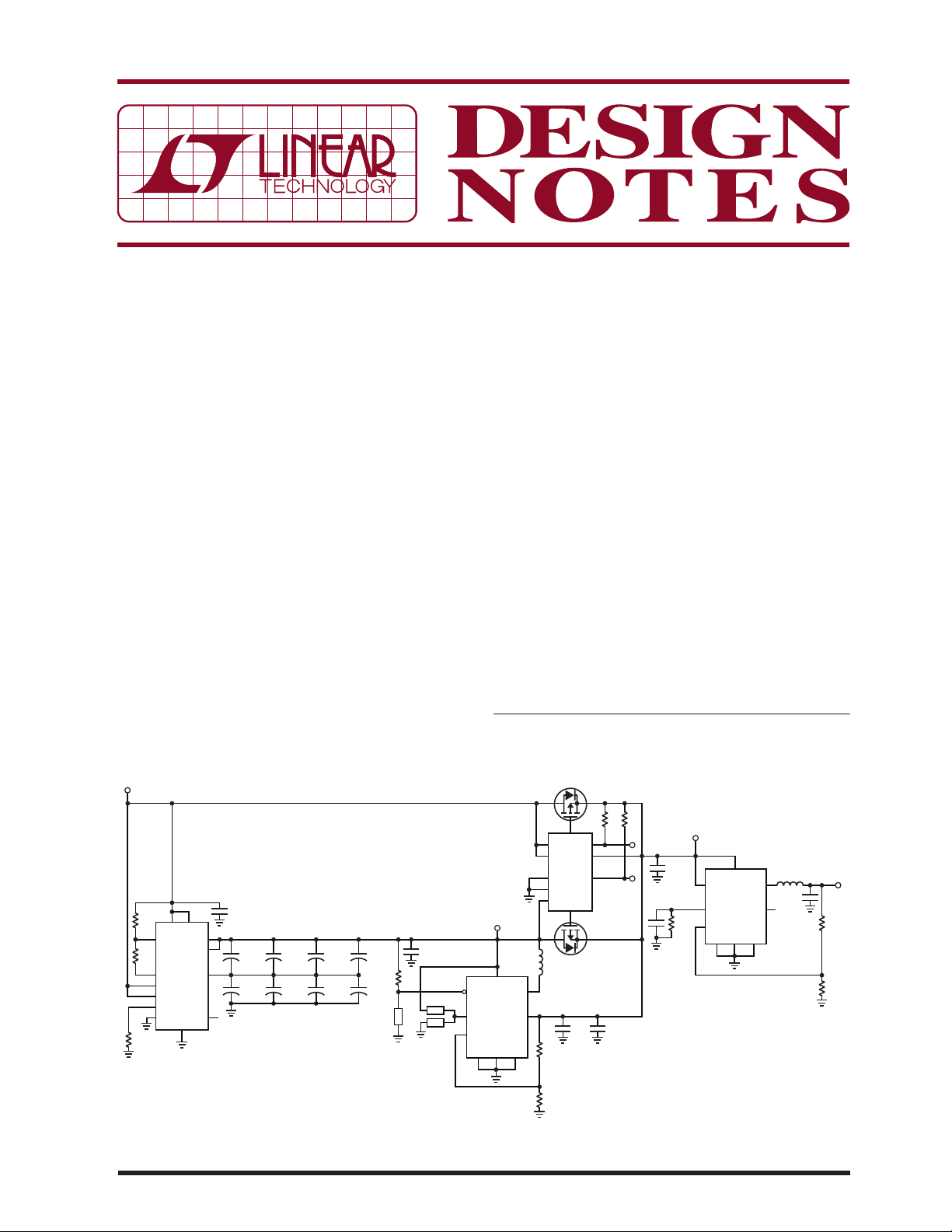
Figure 2 shows the waveforms if the LTC3539 boost
circuit is disabled. Run time from input power off to
ou tput regulator vol t age dropping to 3V is 4.68 seconds.
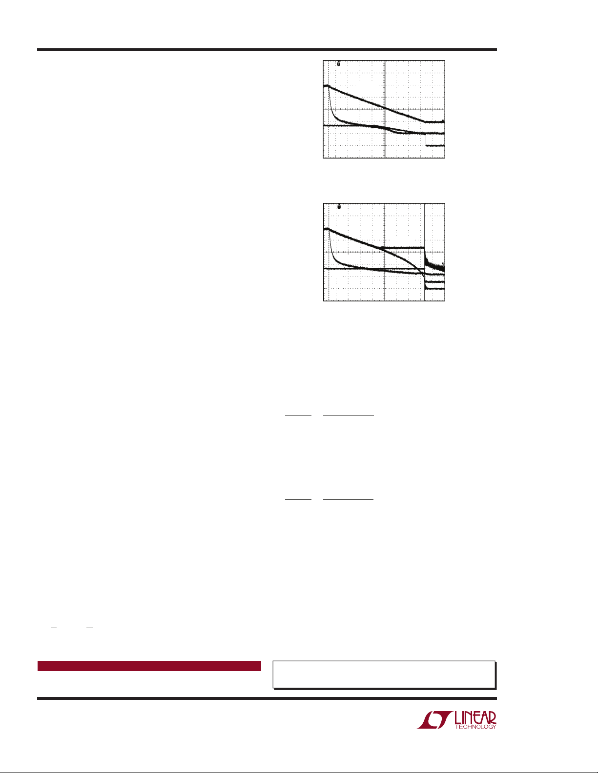
Figure 3 shows the waveforms if the LTC3539 boost
circuit is operational. Run time from input power off
to the output regulator dropping to 3V is 7.92 seconds.
Note in Figure 3 that the output is a steady 3.3V voltage
with a sharp cutoff.
How it Works
When the LTC3539 boost regulator is disabled, as soon
as input power falls, the LTC4416 ideal diodes switch the
input energy supply for the LTC3606 buck regulator to the
supercap. In Figure 2, the voltage across the supercap
) is seen to linearl y decrease due to the constan t power
(V
SC
l o a d of 2 0 0 m A at 3 . 3V o n th e b uc k r e gu l a t or o u t p u t (3 V 3) .
In Figure 3, when the LTC3539 boost regulator is enabled,
the voltage across the supercap (V
) is seen to linearly
SC
decrease due to the constant power load of 200mA at
3.3V on the buck regulator. When the voltage at V
SC
reaches 3.4V, the regulation point of the boost regulator,
the boost regulator begins switching. This shuts off the
ideal diode and disconnects the buck regulator from the
supercapacitor. The energy input to the buck regulator
is now the boost regulator’s output of 3.4V.
Because the input of the buck regulator remains at 3.4V,
its output remains in regulation. When the boost regulator reaches its input UVLO and shuts off, its output
immediately collapses, and the buck regulator shuts off.
Maximizing Usage of the Energy in the Supercap
Because each power conversion lowers the overall effi ciency, the boost circuit should be held off as long as
possible. Therefor e, set the boost regulator outpu t voltage
as close to the buck regulator input dropout voltage as
possible, in this case, 3.4V.
If the supercapacitor is initially charged to 5V, then the
energy in the supercapacitor is 6.875J:
CV2=
1
0.55F • 52= 6.875J
2
1
2
0.67W (3.33 • 0.2A)
Data Sheet Download
www.linear.com
VSC AND
V
IN_BUCK
V
DD
3V3
1 SECOND/DIV
DN485 F02
Figure 2. Power Ride-Through Application Results
without Boost Circuit
V
IN_BUCK
3V3
V
DD
1 SECOND/DIV
V
SC
DN485 F03
Figure 3. Power Ride-Through Application Results with
Boost Circuit Enabled. The Boost Circuit Yields a 40%
Improvement in Run Time
The output power is 3.33V • 0.2A = 0.67W, so the percentage of energy extracted from the full supercap when
the boost regulator is disabled is 45.1%:
ε
LOAD
ε
CAP
0.67 • 4.68s
=
6.875
= 45.1%
The percentage of the energy extracted from the supercap’s available storage when the boost regulator is
enabled is 77%:
ε
LOAD
ε
CAP
0.67 • 7.92s
=
6.875
= 77%
This represents a 40% improvement in ride-through run
time—signifi cant when seconds count.
Conclusion
The run time of any given supercapacitor-based power
r id e-t hr oug h s ys te m c an be e xt en ded by 40 % i f en er gy is
utilized from the dis charging supercap. This is par ticularly
relevant if the supercapacitor charge voltage is reduced
to ensure high temperature reliability.
For applications help,
call (978) 656-3752
Linear Technology Corporation
1630 McCarthy Blvd., Milpitas, CA 95035-7417
(408) 432-1900
●
FAX: (408) 434-0507 ● www.linear.com
dn485f LT/AP 1210 226K • PRINTED IN THE USA
© LINEAR TECHNOLOGY CORPORATION 2010
 Loading...