

Pushbutton On/Off Controller with Failsafe Voltage Monitoring
Design Note 427
Victor Fleury
Introduction
Have you had the exasperating experience of a laptop or
PDA defi antly not responding to your commands? You
frantically press key after key, but to no avail. As hope
turns to anger (but just before you throw the company’s
laptop through the window) you slam your fi nger against
the on/off power button. Ten seconds later, your laptop
fi nally surrenders and the screen goes black in a high
pitched whimper.
The unresponsive pushbutton was likely the result of an
unresponsive μP or system logic—as evidenced by the
crash. By pressing and holding the on/off pushbutton,
the LTC2953 provides the user with the ability to force
system power off, even under fault conditions. This long
pushbutton command works independently of system
logic and automati cally shuts of f power after the adjustabl e
timer expires. The length of time the pushbutton must
be held low in order to force a power down is adjustable
with an external capacitor on the PDT pin.
Pushbutton Challenges
The ON/OFF pushbutton of electronic devices presents
the system designer with a unique set of challenges. The
circuits that monitor the pushbutton translate the chattering pushbutton signal into a clean voltage step that
enables a DC/DC converter or turns on a power switch.
These circuits communicate with system logic to make
sure that power turns on and turns off in an orderly
manner. Additionally, failsafe features should disable
system power if there is a problem with either the input or
output power supply. The pushbutton monitor must also
be rugged: absorb high levels of electrostatic discharge,
tolerate voltage transients below ground and operate at
high voltage levels.
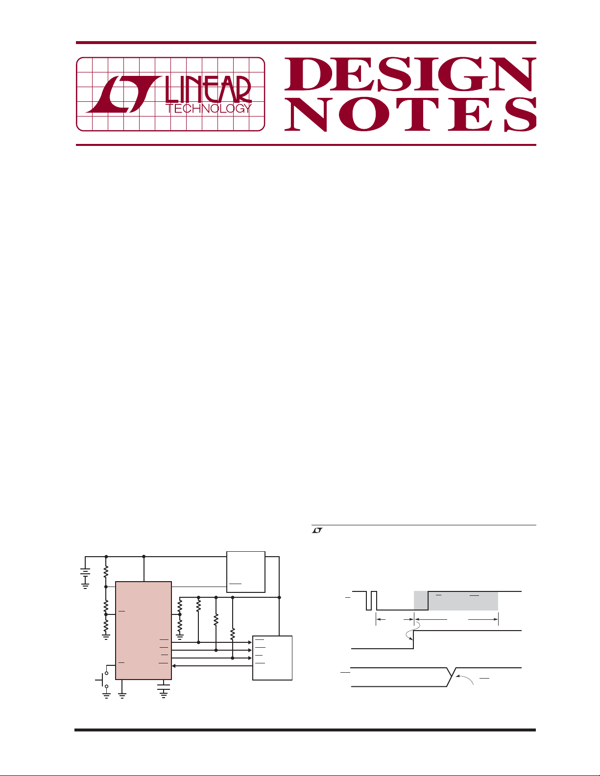
The LTC2953 pushbutton on/off controller with voltage
monitoring addresses all of these issues by providing a
complete solution for in terfacing to the on/of f pushbutton
of electronic devices. This tiny IC integrates the timing
circuitry needed to clean up the pushbutton chatter and
provides a simple communication protocol for orderly
system power turn on and turn off. The LTC2953 includes
a deglitched lockout comp arator that prevents the system
from drawing power from a dead battery or low supply.
The device also provides a single adjustable supply reset
monitor with 200ms delay.
The LTC2953’s wide input voltage range (2.7V to 27V)
is designed to operate from single-cell to multicell battery stacks, thus eliminating the need for a high voltage
, LT, LTC and LTM are registered trademarks of Linear Technology Corporation.
All other trademarks are the property of their respective owners.
V
+
2150k
8.4V 3.3V
ON/OFF
23.2k
196k
UVLO
PFI
PB
GND
LTC2953-1
ENV
IN
100k
499k
VM
100k
RST
PFO
INT
KILL
PDT
1MF
t
= 6.4 SECONDS
PDT
INVOUT
DC/DC
SHDN
100k
100k
Figure 1. Typical Application
10/07/427
RST
GPIO
INT
KILL
SYSTEM
LOGIC
DN427 F01
(LTC2953-1)
KILL
PB
32ms 512ms
EN
DO NOT CARE
Figure 2. Orderly Power On
PB, UVLO AND KILL
IGNORED
SYSTEM SETS
KILL HIGH
DN427 F02
LDO. The part’s feature set allows the system designer to
turn off power to all circuits except the LTC2953, whose
low quiescent current (14μA typical) extends battery
life. The device is available in a space saving 12-lead
3mm × 3mm DFN package.
Orderly Power On
The rugged pushbutton input of the LTC2953 connects
directly to the electronic device’s noisy, chattering mechanical on/off switch. To turn on system power, the
LTC2953 asserts the enable output 32ms after detecting
the end of pushbutton chatter. Once power has been
enabled, the system must set the KILL input high within
512ms. This 512ms timeout period is a failsa fe feature that
prevents the user from turning on the electronic device
when there is a faul ty DC/DC conver ter or an unresponsive
microprocessor. The LTC2953 turns off power if KILL is
not set high during this time window. See Figure 1’s application circuit and Figure 2’s timing diagram.
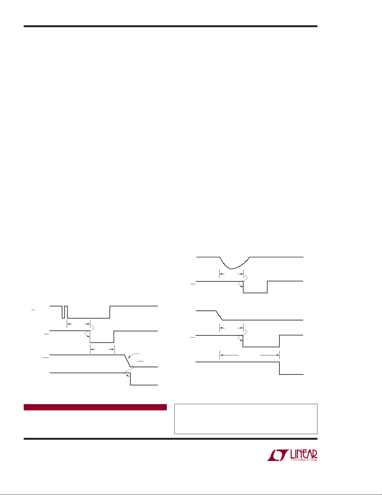
Orderly Power Off: Short Interrupt Pulse
Under normal conditions, an electronic device is turned
off by pulsing the on/off power switch. To turn off system
power, the LTC2953 asserts the interrupt output 32ms
after detecting the end of pushbutton chatter. Upon noticing this interrupt signal, system logic performs power
down and housekeeping tasks and asser ts KILL low when
done. The LTC2953 subsequently releases the enable
output, thus turning off system power (see Figure 3’s
timing diagram).
Failsafe Features
The LTC2953 provides 3 comp arators for voltage monitoring: UVLO, Power Fail and Reset. The UVLO comparator
detects 3 types of aberrant behavior at the input supply.
If the supply glitches for longer than 32ms, the LTC2953
will issue an interrupt signal. If the supply falls and stays
below the user adjustable level, the LTC2953 will turn off
system power after the user-adjustable timer expires.
Additionally, the UVLO comparator prevents a user
from turning on system power if the input supply is too
low (see Figure 4). The power fail is a general purpose
uncommitted comparator, useful for distinguishing
between a PB interrupt and a low supply interrupt. The
reset comparator is a single adjustable voltage monitor
with fi xed 200ms delay.
Conclusion
The LTC2953 is a low power, wide input voltage range
(2.7V to 27V) pushbutton on/off controller with input
and output voltage monitoring. The LTC2953 provides a
simple and comple te solution for manually toggling p ower
of many types of systems. Desirable features include a
power fail comparator that issues an early warning of
a decaying supply, along with a UVLO comparator that
prevents a user from turning on a system with a low supply or dead battery. The LTC2953 provides even greater
system reliability by integrating an adjustable single supply
supervisor. Two versions of the part accommodate either
positive or negative enable polarities. The device is available in a space saving 3mm × 3mm DFN package.
SUPPLY
UVLO
GLITCH
0.5V
32ms
INT
0.55V
32ms
PB OR UVLO
KILL
(LTC2953-1)
INT
EN
SHORT PULSE
32ms
32ms
LTC2953 TURNS
Figure 3. Orderly Power Off
Data Sheet Download
www.linear.com
Linear Technology Corporation
1630 McCarthy Blvd., Milpitas, CA 95035-7417
(408) 432-1900
●
FAX: (408) 434-0507 ● www.linear.com
SYSTEM SETS
KILL LOW
POWER OFF
DN427 F03
LOW SUPPLY GLITCH GENERATES µP INTERRUPT
UVLO
INT
EN
0.5V
LOW SUPPLY INITIATES SYSTEM POWER DOWN AND LOCKS OUT ENABLE
32ms
t
PD, Min
LOW SUPPLY CONDITION
+ t
PDT
Figure 4. Multifunction UVLO Comparator
For applications help,
call (408) 432-1900, Ext. 2602
dn427f LT/TP 1007 451K • PRINTED IN THE USA
© LINEAR TECHNOLOGY CORPORATION 2007
LOW SUPPLY
LOCKS OUT
ENABLE
DN427 F04
 Loading...