

Page 1
advertisement
Accurate Power Supply Sequencing Prevents System Damage
Design Note 384
Jeff Heath and Akin Kestelli
Introduction
Many complex systems—such as telecom equipment,
memory modules, optical systems, networking equipment, servers and base stations—use FPGAs and other
digital ICs that require multiple voltage rails that must
start up and shut down in a specific order, otherwise the
ICs can be damaged. The LTC
®
2924 is a simple and
compact solution to power supply sequencing in a 16-pin
SSOP package (see Figures 1 and 2).
How it Works
Four power supplies can be easily sequenced using a
single LTC2924 and multiple LTC2924s can be just as
easily cascaded to sequence any number of power supplies. With slightly reduced functionality, six power supplies can be sequenced with a single LTC2924.
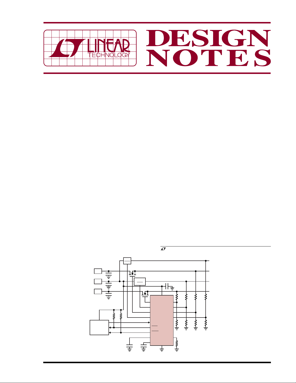
The LTC2924 controls the start-up and shutdown sequence and ramp rates of four power supply channels via
output pins (OUT1 to OUT4). Each OUT pin uses a 10µA
current source connected to an internal charge pump and
a low resistance switch to GND. This combination makes
the outputs flexible enough to connect them directly to
3.3V
SHDN
150nF
Q2
150nF
5V TO 5V
SHDN
Q1
OUT1
OUT2
OUT3
OUT4
ON
DONE
FAULT
TMR
PGT
03/06/384
1V
5V
3V
SYSTEM
CONTROLLER
0.1µF
0.1µF
0.1µF
5V EARLY
10k 10k
Figure 1. Typical Application with External N-Channel MOSFETs
many power supply shutdown pins or to external Nchannel MOSFET switches.
The LTC2924 monitors the output voltage of each sequenced power supply via four input pins (IN1 to IN4).
These inputs use precision comparators and a trimmed
bandgap voltage reference to provide better than 1%
accuracy. The power ON and power OFF voltage thresholds are set using resistive dividers for each of the four
channels. The power ON threshold and the power OFF
threshold are individually selectable on a channel by
channel basis (see “Selecting the Hysteresis Current and
IN Pin Feedback Resistors” in the data sheet for details).
The LTC2924 timer pin (TMR) is used to provide an
optional delay between the completion of start-up of one
supply and the start-up of the next power supply. The
delay time is selected by placing a capacitor between the
TMR pin and ground (delay = 200ms/µF), whereas floating the TMR pin removes any delay. The start-up delay can
be different than the shutdown delay. Figure 3 shows a
simple circuit where the shutdown delay is half the startup delay.
, LTC and LT are registered trademarks of Linear Technology Corporation.
All other trademarks are the property of their respective owners.
V
= 2.64V
ON
= 1.98V
V
OFF
V
= 0.93V
ON
= 0.915V
V
OFF
VON = 3.97V
= 2.97V
V
OFF
VON = 2.79V
V
OFF
20k
= 2.73V
V
CC
LTC2924
HYS/CFG
GND
IN1
IN2
IN3
IN4
0.1µF
6.04k
100k 1.62k 66.5k
1.69k
18.2k 3.09k
Q1-Q2: IRL3714S
ALL RESISTORS 1%
49.9k
DN384 F01
Page 2
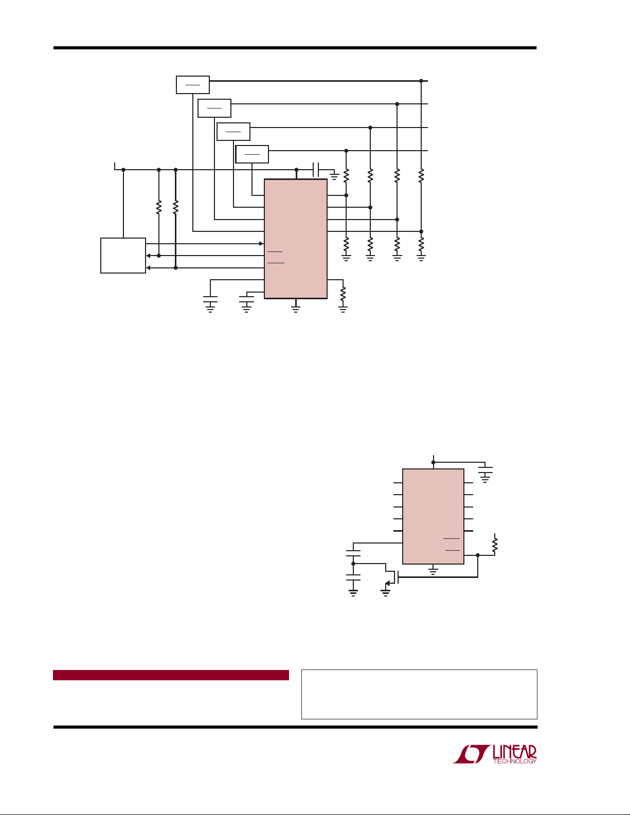
POWER SUPPLY 1
POWER SUPPLY 2
POWER SUPPLY 3
5V EARLY*
CONTROLLER
*5V EARLY MUST BE ON BEFORE
SEQUENCING SUPPLIES
POWER SUPPLY 4
10k
SYSTEM
Figure 2. Four Power Supply Sequencer Using Shutdown Pins
10k
3.3V
SHDN
150nF
5V
SHDN
1.6V
SHDN
150nF
2.5V
SHDN
OUT1
OUT2
OUT3
OUT4
ON
DONE
FAULT
TMR
PGT
V
CC
LTC2924
GND
IN1
IN2
IN3
IN4
HYS/CFG
0.1µF
24.9k
15.8k 49.9k
9.31k
11.81k 7.87k 8.45k
49.9k
DN384 F02
V
V
V
V
V
V
V
V
33.2k
ON
OFF
ON
OFF
ON
OFF
ON
OFF
3.01V
2.68V
4.49V
3.99V
1.43V
1.27V
2.25V
2V
The LTC2924 also includes a power good timer (PGT).
The LTC2924 starts the PGT as each individual power
supply is enabled. If any power supply fails to reach its
nominal specified voltage within the allotted time interval,
a power ON fault is detected.
Conclusion
The LTC2924 fits into a wide variety of power supply
sequencing and monitoring applications. With very few
external components and a 16-pin narrow SSOP, an
LTC2924-based sequencing solution requires very little
board space.
The power supply enable pins require no configuration by
the designer, yet are versatile enough to directly drive
shutdown pins or external N-channel MOSFETs. Softstart of power supplies can be achieved simply by adding
a capacitor. If the sequencing of more than four power
supplies is required, the LTC2924 can be cascaded to
sequence a virtually unlimited number of power supplies.
Tailoring the LTC2924 to a specific application requires no
software and designs can be fine tuned during system
integration simply by changing resistor and capacitor
values. Ease of design, low component cost, and a small
footprint make the LTC2924 an excellent choice for power
supply sequencing and monitoring.
V
CC
DN384 F03
V
0.1µF
CC
10k
V
CC
LTC2924
GND
OUT1
OUT2
OUT3
OUT4
PGT
FAULT
DONE
150nF
150nF
2N7002
IN1
IN2
IN3
IN4
ON
TMR
POWER ON TIMER DELAY = 30ms
POWER OFF TIMER DELAY = 15ms
Figure 3. Programming Different ON/OFF Delays
Data Sheet Download
www.linear.com
Linear Technology Corporation
1630 McCarthy Blvd., Milpitas, CA 95035-7417
(408) 432-1900 ● FAX: (408) 434-0507 ● www.linear.com
For applications help,
call (408) 432-1900, Ext. 2452
dn384 LT/TP 0306 409K • PRINTED IN THE USA
© LINEAR TECHNOLOGY CORPORATION 2005
 Loading...