

Linear Technology LTC1998IS6, LTC1998CS6 Datasheet
SOT-23 Comparator and Voltage
Reference for Battery Monitoring
FEATURES
■
High Accuracy Trip Voltage: 1% Max Error Using
External 1% Resistors
■
Adjustable Threshold Voltage and Hysteresis
■
Quiescent Current: 2.5µA Typ
■
Output Swings Rail-to-Rail
■
Thresholds Programmable from 2.5V to 3.25V
■
Output State Guaranteed for V
■
Low Profile (1mm) ThinSOT
BATT
TM
Package
≥ 1.5V
LTC1998
2.5µA, 1% Accurate
U
DESCRIPTIO
The LTC®1998 is a micropower comparator and a precision adjustable reference in a 6-pin SOT-23 package that
is optimized for lithium-ion low battery detection circuits.
The LTC1998 features a voltage detection circuit with an
adjustable threshold voltage and hysteresis. The threshold voltage can be programmed from 2.5V to 3.25V with
two external resistors. A 10mV to 750mV hysteresis can
be added with a third external resistor.
U
APPLICATIO S
■
Lithium-Ion Battery-Powered Equipment
PDAs
Cell Phones
Handheld Instruments
Battery Packs
Pagers
Palm Top Computers
POS Terminals
, LTC and LT are registered trademarks of Linear Technology Corporation.
ThinSOT is a trademark of Linear Technology Corporation.
W
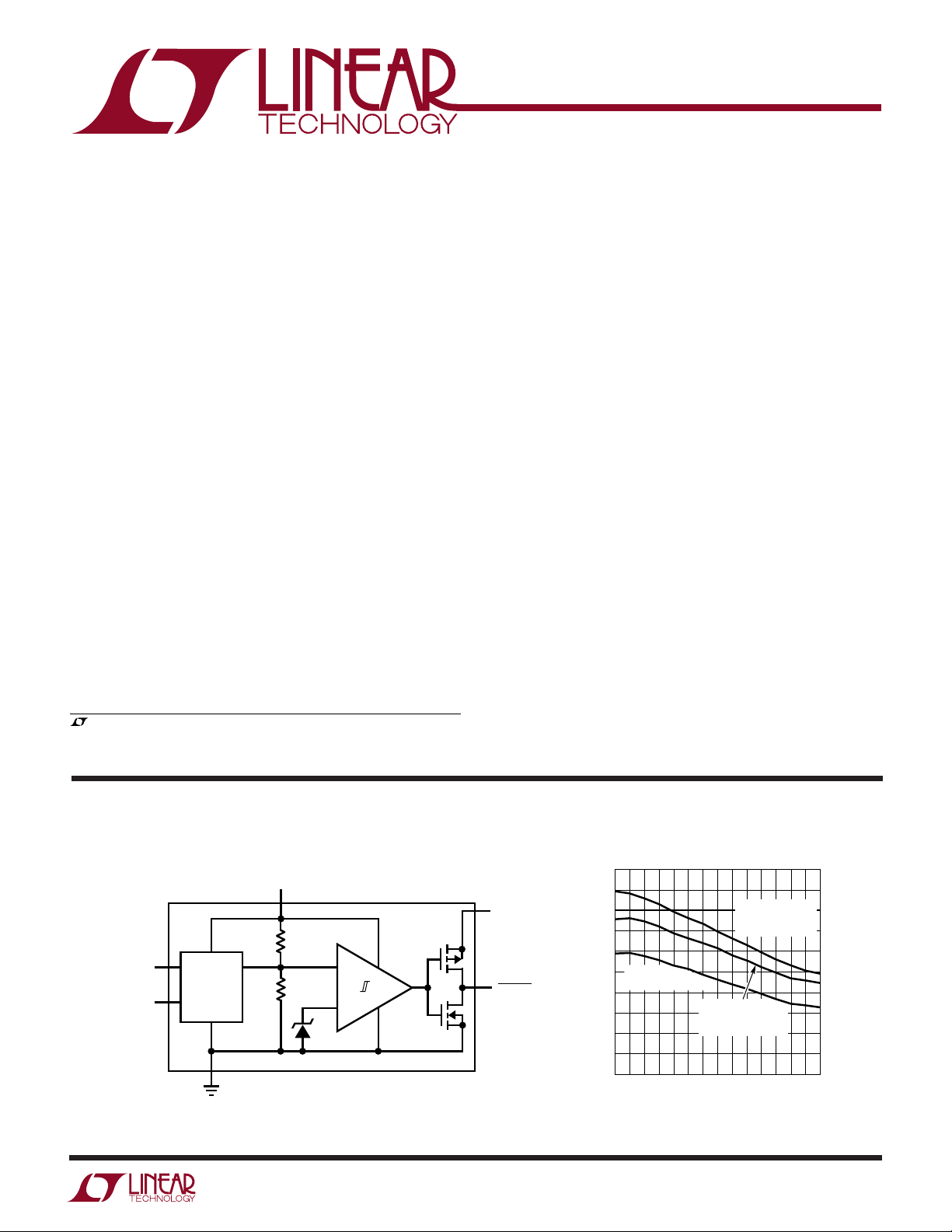
BLOCK DIAGRA
BATT
1.1R
V
HYST.A
V
TH.A
THRESHOLD
ADJUST
R
1.2V
A proprietary internal architecture maintains 1% threshold voltage accuracy over temperature with low cost 1%
external resistors.
A separate power supply pin, V
, allows the battery-
LOGIC
low logic output to operate below the battery voltage,
allowing compatibility with low voltage microprocessors
without a pull-up resistor. Power supply glitches are
eliminated by preventing the cross-conducting current
which occurs when the output changes state.
The LTC1998 operates with battery or supply voltages up
to 5.5V and its battery-low output is valid for battery
voltages above 1.5V.
Threshold Voltage Error vs Temperature
1.0
0.9
V
SET BY 1%
V
LOGIC
BATTLO
1998 BD
0.8
0.7
0.6
V
0.5
% ERROR
0.4
0.3
0.2
0.1
0
–45 15 55
1V
TH.A =
THRESHOLD = 3V
–25 –5
TEMPERATURE (°C)
TH.A
EXTERNAL R,
THRESHOLD = 3V
V
SHORTED
TH.A
TO GROUND,
THRESHOLD = 2.5V
35 75 95
1998 G05
1998f
1
LTC1998
WW
W
ABSOLUTE AXI U RATI GS
U
UUW
PACKAGE/ORDER I FOR ATIO
(Note 1)
ORDER PART
Total Supply Voltage (BATT or V
to GND) ......... 6V
LOGIC
Voltage
V
, V
TH.A
...........................
H.A
BATTLO ........................ V
BATT + 0.3V to GND – 0.3V
+ 0.3V to GND – 0.3V
LOGIC
Operating Temperature Range (Note 3) ...–40°C to 85°C
Specified Temperature Range (Note 4)
LTC1998C ...........................................–40°C to 85°C
BATT 1
GND 2
V
TH.A
TOP VIEW
3
S6 PACKAGE
6-LEAD PLASTIC SOT-23
T
= 150°C, θJA = 250°C/W
JMAX
6 BATTLO
5 V
LOGIC
4 V
H.A
NUMBER
LTC1998CS6
LTC1998IS6
S6 PART MARKING*
LTTY
LTC1998I.............................................–40°C to 85°C
Storage Temperature Range ................. –65°C to 150°C
Lead Temperature (Soldering, 10 sec).................. 300°C
ELECTRICAL CHARACTERISTICS
temperature range, otherwise specifications are at TA = 25°C. V
PARAMETER CONDITIONS MIN TYP MAX UNITS
Power Supply
Supply Voltage Range-BATT ● 1.5 5.5 V
Supply Voltage Range-V
Supply Current, V
V
= 1.5V LTC1998CS6 ● 4.2 µA
TH.A
Supply Current, V
V
= 1.5V LTC1998CS6 ● 5.2 µA
TH.A
Monitor
Threshold Accuracy V
Hysteresis Accuracy V
Allowable Hysteresis Range (Note 2) ● 10 750 mV
Propagation Delay C
Threshold Adjust Pin Leakage, I
Hysteresis Adjust Pin Leakage, I
Output
BATTLO High Voltage I
BATTLO Low Voltage I
BATTLO Low Voltage I
LOGIC
= 3V, TA = 25°C 2.5 3.5 µA
BATT
LTC1998IS6 ● 4.5 µA
= 5.5V, TA = 25°C 3 4.3 µA
BATT
LTC1998IS6 ● 5.5 µA
= 2.5V, Pin 3 Shorted to Ground 0.6 0.85 %
BATT.Th
V
= 3V, Pin 3 Driven by Precision LTC1998C ● 0.5 0.61 %
BATT.Th
Voltage Source to 1V LTC1998I
V
= 3V, V
BATT.Th
Programmed with 1% Max External Resistors LTC1998I ● 0.9 1.1 %
V
BATT.Th
Voltage Source to 1.5V LTC1998I ● 0.7 0.85 %
V
BATT.Th
Programmed with1% Max External Resistors LTC1998I
≤ 250mV ● –5 5 mV
HYST
250mV ≤ V
= 100pF, Overdrive = 10mV 350 µs
OUT
TH.AVTH.A
H.AVH.A
≤ 1.5V ● 0.01 1 nA
≤ 1.5V ● 0.01 1 nA
= –1mA ● V
OUT
= 1mA, V
OUT
= 0.25mA, V
OUT
TH.A
= 3.25V, Pin 3 Diven by Precision LTC1998C ● 0.6 0.65 %
= 3.25V, V
TH.A
≤ 750mV ● ±5mV
HYST
Overdrive = 100mV 150 µs
≥ 2V ● 0.2 V
BATT
BATT
The ● denotes the specifications which apply over the full operating
= 1V (Note 5) LTC1998C ● 0.8 1 %
= 1.5V (Note 5) LTC1998C ● 0.9 1.1 %
= 1V ● 0.3 V
*The temperature grades are indentified by a label on the shipping container.
Consult LTC Marketing for parts specified with wider operating temperature ranges.
= 0V, unless otherwise noted.
GND
● 1V
● 0.8 1 %
● 0.6 0.71 %
● 1 1.3 %
– 0.3 V
LOGIC
BATT
1998f
V
2
ELECTRICAL CHARACTERISTICS
LTC1998
Note 1: Absolute Maximum Ratings are those values beyond which the life
of a device may be impaired.
Note 2: Maximum allowable hysteresis depends on desired trip voltages.
See application notes for details.
Note 3: LTC1998C and LTC1998I are guaranteed functional over the
operating temperature range of –40°C to 85°C.
Note 4: The LTC1998C is guaranteed to meet specified performance from
0°C to 70°C. The LTC1998C is designed, characterized and expected to
meet specified performance from –40°C to 85°C but is not tested or QA
sampled at these temperatures. The LTC1998I is guaranteed to meet
specified performance from –40°C to 85°C.
Note 5: This parameter is not 100% tested.
UW
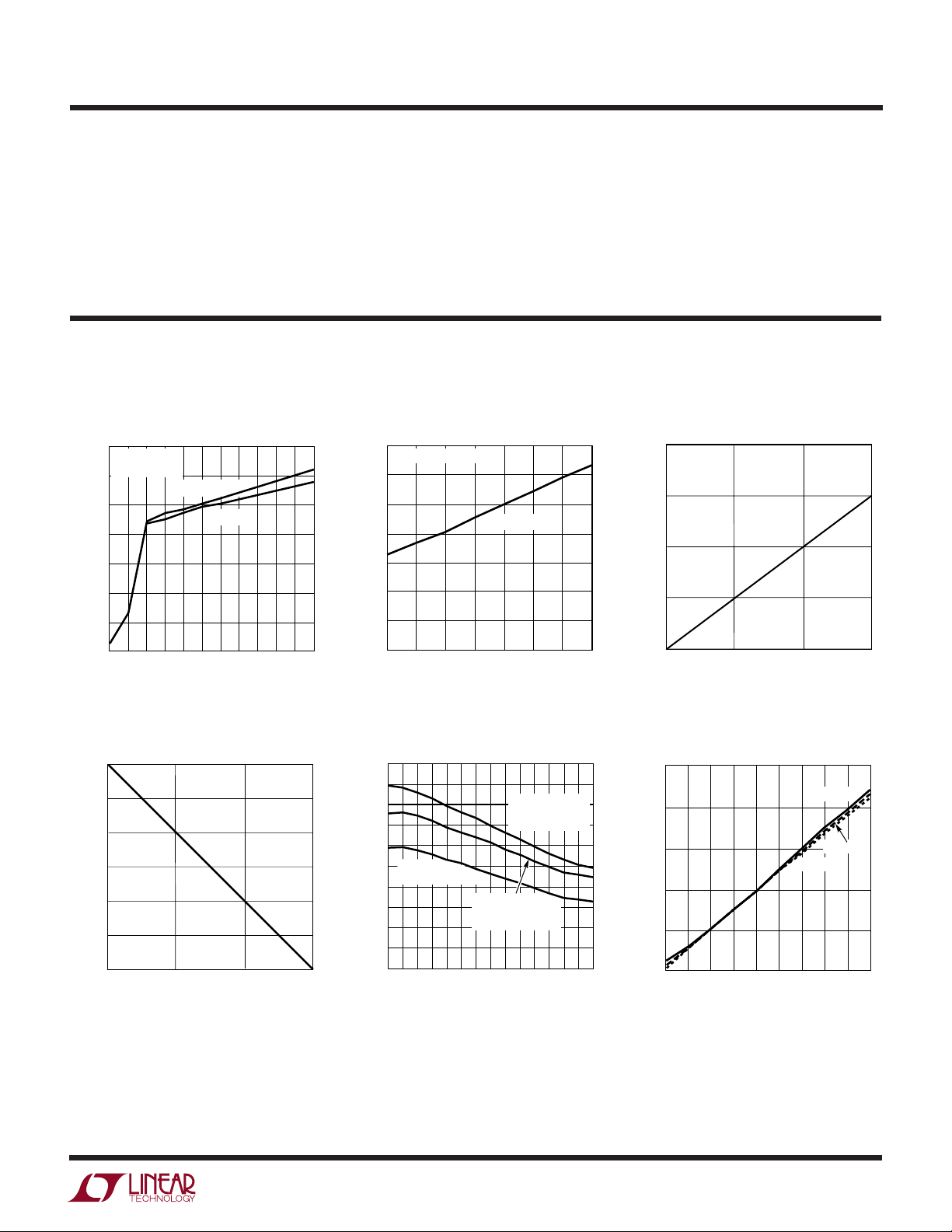
TYPICAL PERFOR A CE CHARACTERISTICS
Quiescent Supply Current vs
Supply Voltage
3.5
TA = 25°C
= V
V
LOGIC
3.0
2.5
2.0
1.5
1.0
SUPPLY CURRENT (µA)
0.5
BATT
V
= 1.5V
TH.A
V
TH.A
= 0V
Quiescent Supply Current vs
Temperature
3.5
V
= V
LOGIC
= 3V
V
BATT
3.0
2.5
2.0
1.5
1.0
SUPPLY CURRENT (µA)
0.5
TH.A
= 1.5V
Threshold Voltage vs Threshold
Adjust Voltage
3.5
3.0
THRESHOLD VOLTAGE (V)
0
0.5 1.0 1.5 2.0 2.5 3.0 3.5 4.0 4.5 5.0 5.5 6.0
SUPPLY VOLTAGE (V)
Available Hysteresis vs
Threshold Voltage
750
500
250
AVAILABLE HYSTERESIS (mV)
0
2.5
2.75 3.0
LOW BATTERY THRESHOLD VOLTAGE (V)
1998 G01
1998 G04
3.25
0
–50 –30 –10 10 30 50 70 90
TEMPERATURE (°C)
Threshold Voltage Error vs
Temperature
1.0
0.9
V
SET BY 1%
0.8
0.7
0.6
V
0.5
% ERROR
0.4
0.3
0.2
0.1
0
–45 15 55
1V
TH.A =
THRESHOLD = 3V
–25 –5
TEMPERATURE (°C)
TH.A
EXTERNAL R,
THRESHOLD = 3V
V
SHORTED
TH.A
TO GROUND,
THRESHOLD = 2.5V
35 75 95
1998 G02
1998 G05
2.5
0
0.5 1.0
THRESHOLD ADJUST VOLTAGE (V)
Input Current vs Temperature
10000
1000
(pA)
H.A
, V
100
TH.A
10
1
INPUT CURRENT V
0.1
45 65
35
55
75
TEMPERATURE (°C)
1.5
1998 G03
VIN = 1.5V
VIN = 1V
VIN = 0.5V
105
85 125
115
95
1998 G06
1998f
3
 Loading...