

FEATURES
LTC1734
Lithium-Ion Linear
Battery Charger in ThinSOT
U
DESCRIPTIO
■
Low Profile (1mm) ThinSOTTM Package
■
No Blocking Diode Required
■
No Sense Resistor Required
■
1% Accurate Preset Voltages: 4.1V or 4.2V
■
Charge Current Monitor Output
for Charge Termination
■
Programmable Charge Current: 200mA to 700mA
■
Automatic Sleep Mode with Input Supply Removal
■
Manual Shutdown
■
Negligible Battery Drain Current in Shutdown
■
Undervoltage Lockout
■
Self Protection for Overcurrent/Overtemperature
U
APPLICATIO S
■
Cellular Telephones
■
Handheld Computers
■
Digital Cameras
■
Charging Docks and Cradles
■
Low Cost and Small Size Chargers
■
Programmable Current Sources
The LTC®1734 is a low cost, single cell, constant-current/
constant-voltage Li-Ion battery charger controller. When
combined with a few external components, the SOT-23
package forms a very small, low cost charger for single cell
lithium-ion batteries.
The LTC1734 is available in 4.1V and 4.2V versions with
1% accuracy. Constant current is programmed using a
single external resistor between the PROG pin and ground.
Manual shutdown is accomplished by floating the program resistor while removing input power automatically
puts the LTC1734 into a sleep mode. Both the shutdown
and sleep modes drain near zero current from the battery.
Charge current can be monitored via the voltage on the
PROG pin allowing a microcontroller or ADC to read the
current and determine when to terminate the charge cycle.
The output driver is both current limited and thermally
protected to prevent the LTC1734 from operating outside
of safe limits. No external blocking diode is required.
The LTC1734 can also function as a general purpose
current source or as a current source for charging nickelcadmium (NiCd) and nickel-metal-hydride (NiMH) batteries using external termination.
, LTC and LT are registered trademarks of Linear Technology Corporation.
ThinSOT is a trademark of Linear Technology Corporation.
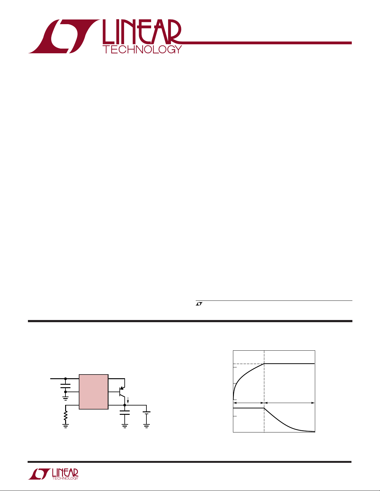
TYPICAL APPLICATIO
300mA Li-Ion Battery Charger
V
IN
5V
1µF
31
2
4
R
PROG
5k
V
CC
LTC1734
GND
PROG
I
SENSE
DRIVE
BAT
6
5
U
FMMT549
I
BAT
10µF
= 300mA
+
SINGLE
Li-Ion
BATTERY
1734 TA01
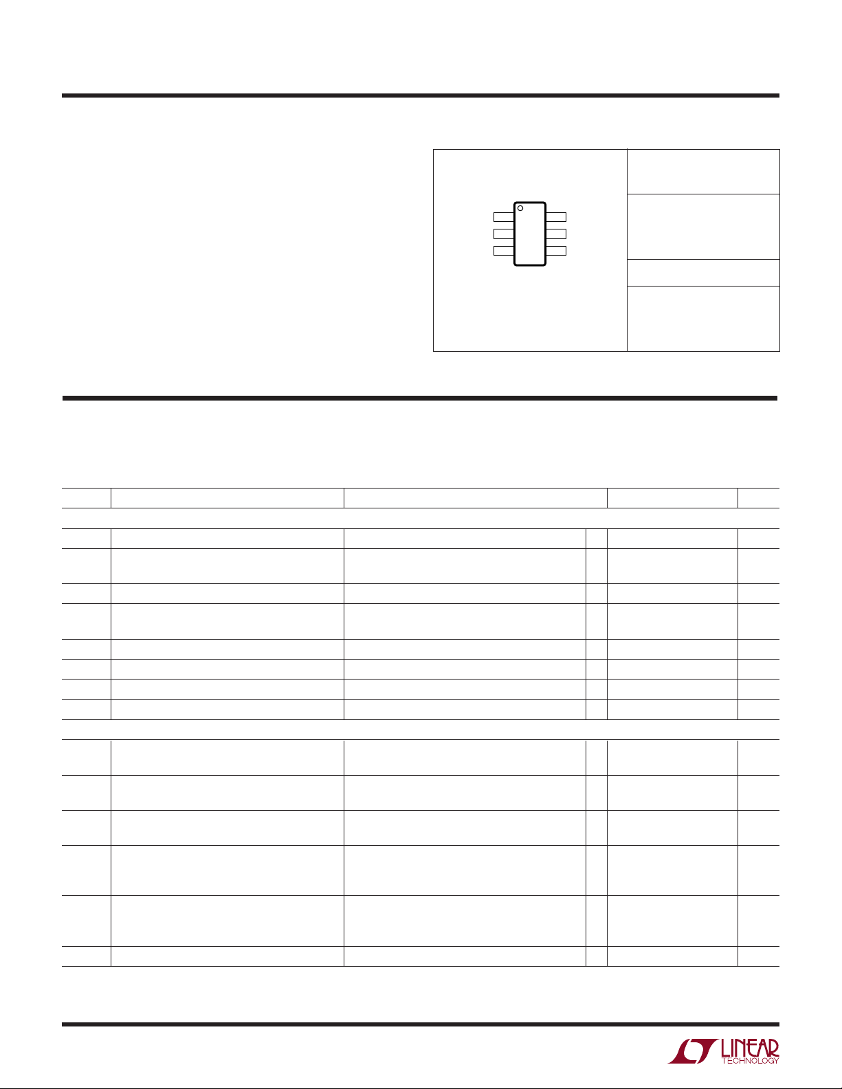
PROG Pin Indicates Charge Status
5V
V
(V)V
4V
BAT
V
3V
2V
1.5V
(V)
1V
PROG
0V
CHARGING
BEGINS
CONSTANT
CURRENT
BAT
V
CONSTANT
VOLTAGE
PROG
CHARGING
COMPLETE
1734 TA01b
1
LTC1734
WW
W
ABSOLUTE MAXIMUM RATINGS
U
U
W
PACKAGE/ORDER INFORMATION
(Note 1)
Supply Voltage (VCC) ...................................–0.3V to 9V
Input Voltage (BAT, PROG) ........ –0.3V to (VCC + 0.3V)
Output Voltage (DRIVE) .............. –0.3V to (VCC + 0.3V)
Output Current (I
) ................................... –900mA
SENSE
Short-Circuit Duration (DRIVE) ...................... Indefinite
Junction Temperature.......................................... 125°C
Operating Ambient Temperature Range
(Note 2) ...............................................–40°C to 85°C
Operating Junction Temperature (Note 2) ............ 100°C
TOP VIEW
I
1
SENSE
GND 2
3
V
CC
S6 PACKAGE
6-LEAD PLASTIC SOT-23
T
= 125°C, θJA = 230°C/W
JMAX
6 DRIVE
5 BAT
4 PROG
ORDER PART
NUMBER
LTC1734ES6-4.1
LTC1734ES6-4.2
S6 PART MARKING
LTHD
LTRG
Storage Temperature Range ................. –65°C to 150°C
Lead Temperature (Soldering, 10 sec).................. 300°C
ELECTRICAL CHARACTERISTICS
temperature range, otherwise specifications are at TA = 25°C. VCC = 5V, GND = 0V and V
otherwise noted. All current into a pin is positive and current out of a pin is negative. All voltages are referenced to GND, unless
otherwise specified.
SYMBOL PARAMETER CONDITIONS MIN TYP MAX UNITS
VCC Supply
V
CC
I
CC
I
SHDN
I
BMS
I
BSL
V
UVLOI
V
UVLOD
V
UVHYS
Charging Performance
V
BAT
I
BAT1
I
BAT2
V
CM1
V
CM2
I
DSINK
Operating Supply Range (Note 5) ● 4.55 8 V
Quiescent VCC Pin Supply Current V
VCC Pin Supply Current in Manual Shutdown PROG Pin Open ● 450 900 µA
Battery Drain Current in Manual Shutdown PROG Pin Open ● –1 0 1 µA
(Note 3)
Battery Drain Current in Sleep Mode (Note 4) VCC = 0V ● –1 0 1 µA
Undervoltage Lockout Exit Threshold VCC Increasing ● 4.45 4.56 4.68 V
Undervoltage Lockout Entry Threshold VCC Decreasing ● 4.30 4.41 4.53 V
Undervoltage Lockout Hysteresis VCC Decreasing 150 mV
Output Float Voltage in Constant Voltage Mode 4.1V Version, I
Output Full-Scale Current When Programmed R
for 200mA in Constant Current Mode Pass PNP Beta > 50
Output Full-Scale Current When Programmed R
for 700mA in Constant Current Mode Pass PNP Beta > 50
Current Monitor Voltage on PROG Pin I
Current Monitor Voltage on PROG Pin I
Drive Output Current V
The ● denotes the specifications which apply over the full operating
= 5V, (Forces I
BAT
= 200µA,(7500Ω from PROG to GND)
I
PROG
4.2V Version, I
= 7500Ω, 4.55V ≤ VCC ≤ 8V, ● 155 200 240 mA
PROG
= 2143Ω, 4.55V ≤ VCC ≤ 8V, ● 620 700 770 mA
PROG
= 10% of I
BAT
4.55V ≤ V
≤ 85°C
0°C ≤ T
A
= 10% of I
BAT
4.55V ≤ V
0°C ≤ T
≤ 85°C
A
= 3.5V ● 30 mA
DRIVE
Consult LTC Marketing for parts specified with wider operating temperature ranges.
is equal to the float voltage unless
BAT
= I
DRIVE
= 10mA, 4.55V ≤ VCC ≤ 8V ● 4.059 4.10 4.141 V
BAT
= 10mA, 4.55V ≤ VCC ≤ 8V ● 4.158 4.20 4.242 V
BAT
, R
BAT1
BAT2
, R
PROG
PROG
≤ 8V, Pass PNP Beta > 50,
CC
≤ 8V, Pass PNP Beta > 50,
CC
= 0), ● 670 1150 µA
BAT
= 7500Ω, 0.045 0.15 0.28 V
= 2143Ω, 0.10 0.15 0.20 V
U
2
LTC1734
TEMPERATURE (°C)
–50
190
I
BAT1
(mA)
200
210
0
50
75
1734 G03
–25
25
100
125
R
PROG
= 7.5k
PNP = FCX589
VCC = 4.55V AND 8V
ELECTRICAL CHARACTERISTICS
temperature range, otherwise specifications are at TA = 25°C. VCC = 5V, GND = 0V and V
The ● denotes the specifications which apply over the full operating
is equal to the float voltage unless
BAT
otherwise noted. All current into a pin is positive and current out of a pin is negative. All voltages are referenced to GND, unless
otherwise specified.
SYMBOL PARAMETER CONDITIONS MIN TYP MAX UNITS
Charger Manual Control
V
MSDT
V
MSHYS
I
PROGPU
Protection
I
DSHRT
Note 1: Absolute Maximum Ratings are those values beyond which the life
of a device may be impaired.
Note 2: The LTC1734E is guaranteed to meet performance specifications
from 0°C to 70°C ambient temperature range and 0°C to 100°C junction
temperature range. Specifications over the –40°C to 85°C operating
ambient temperature range are assured by design, characterization and
correlation with statistical process controls.
Note 3: Assumes that the external PNP pass transistor has negligible B-C
reverse-leakage current when the collector is biased at 4.2V (V
base is biased at 5V (V
Manual Shutdown Threshold V
Manual Shutdown Hysteresis V
Programming Pin Pull-Up Current V
Drive Output Short-Circuit Current Limit V
).
CC
Increasing ● 2.05 2.15 2.25 V
PROG
Decreasing from V
PROG
= 2.5V –6 –3 –1.5 µA
PROG
= V
DRIVE
CC
MSDT
● 35 65 130 mA
90 mV
Note 4: Assumes that the external PNP pass transistor has negligible B-E
reverse-leakage current when the emitter is biased at 0V (V
base is biased at 4.2V (V
BAT
).
CC
Note 5: The 4.68V maximum undervoltage lockout (UVLO) exit threshold
must first be exceeded before the minimum V
Short duration drops below the minimum V
specification applies.
CC
specification of several
CC
microseconds or less are ignored by the UVLO. If manual shutdown is
entered, then VCC must be higher than the 4.68V maximum UVLO
) and the
BAT
threshold before manual shutdown can be exited. When operating near the
minimum V
, a suitable PNP transistor with a low saturation voltage
CC
must be used.
) and the
UW
TYPICAL PERFOR A CE CHARACTERISTICS
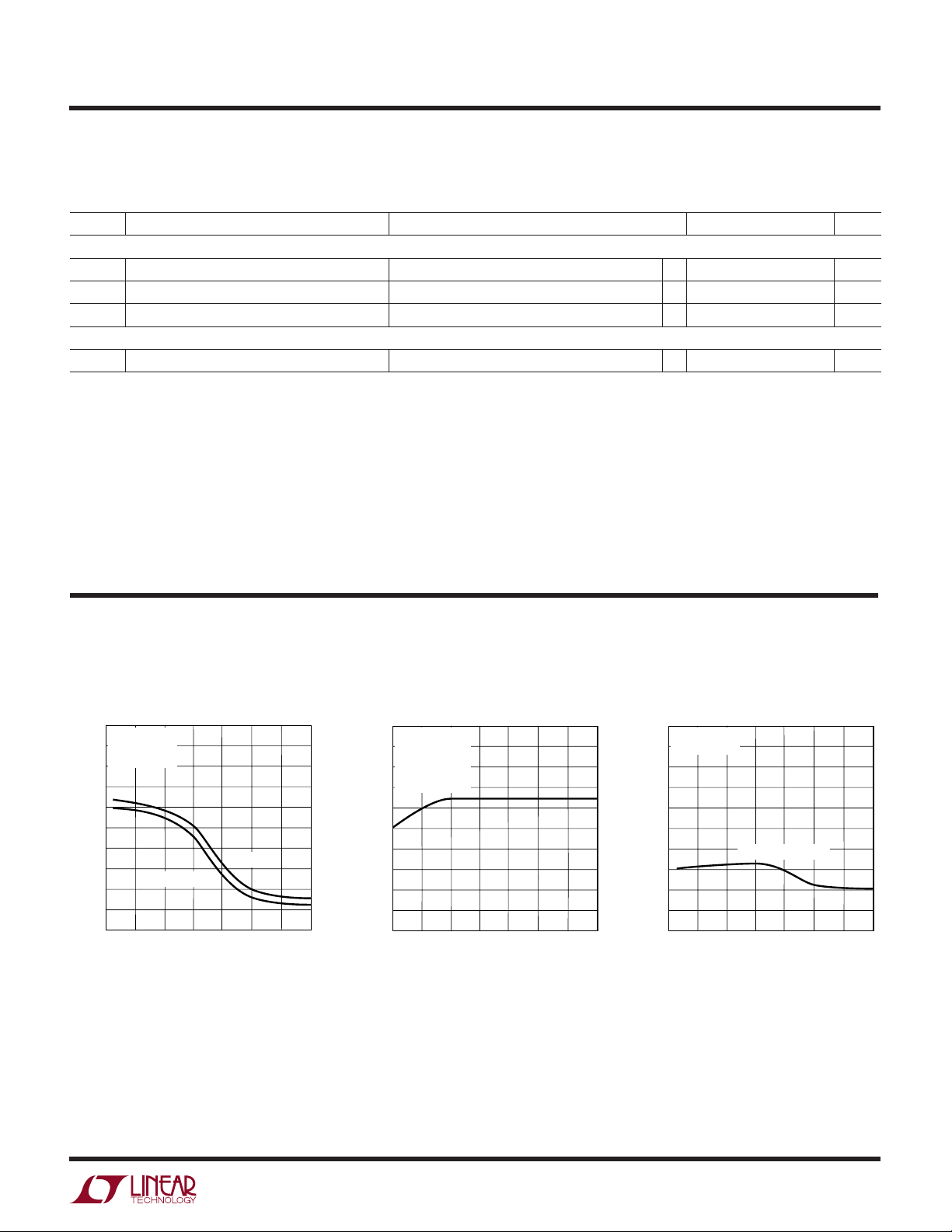
Float Voltage vs Temperature
4.21
4.20
FLOAT VOLTAGE (V)
4.19
and Supply Voltage
I
= 10mA
BAT
PNP = FCX589
4.2V OPTION
V
= 4.55V
CC
25
–25
0
TEMPERATURE (°C)
–50
VCC = 8V
50
100
125
1734 G01
75
Float Voltage vs I
4.201
VCC = 5V
= 25°C
T
A
PNP = FCX589
4.2V OPTION
= 2150Ω
R
PROG
4.200
FLOAT VOLTAGE (V)
4.199
0
100
200
300
I
BAT
BAT
400
(mA)
500
600
1734 G02
700
I
vs Temperature
BAT1
and Supply Voltage
3
LTC1734
TEMPERATURE (°C)
–50
140
V
PROG
(mV)
150
160
0
50
75
1734 G12
–25
25
100
125
R
PROG
= 2.15k
PNP = FCX589
VCC = 8V
V
CC
= 4.55V
UW
TYPICAL PERFOR A CE CHARACTERISTICS
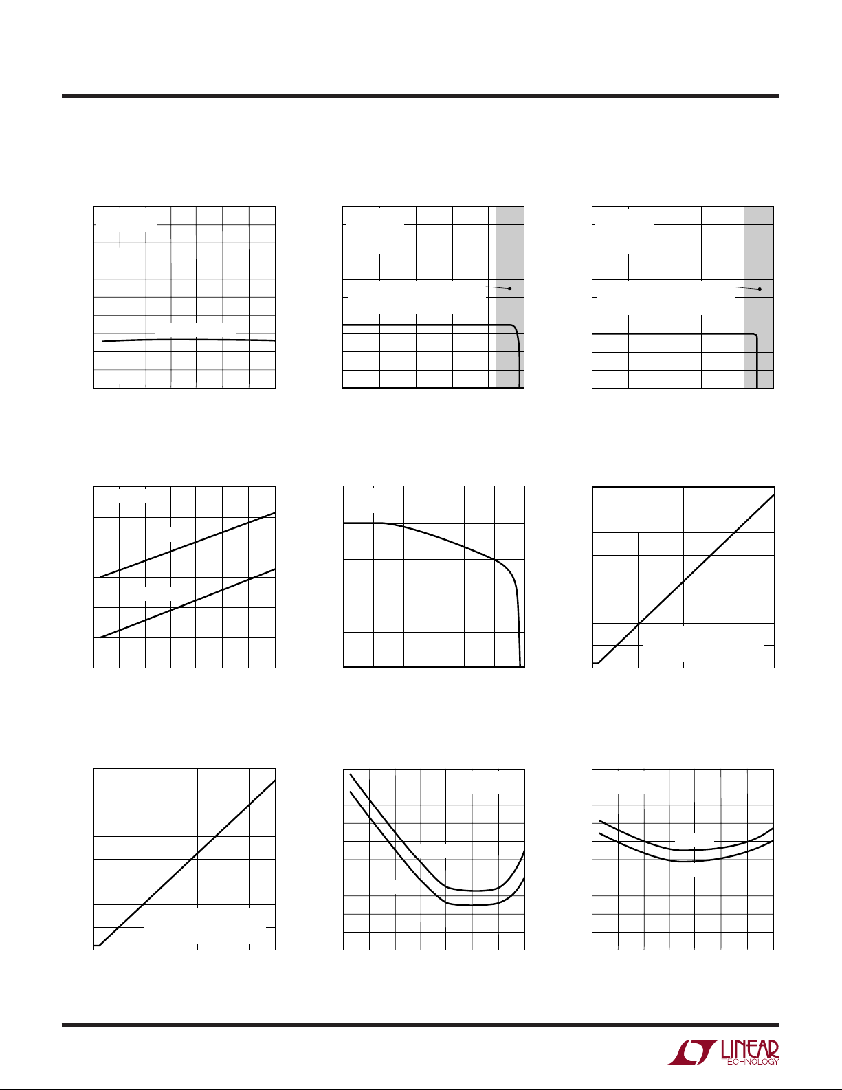
I
vs Temperature
BAT2
and Supply Voltage
740
R
= 2.15k
PROG
PNP = FCX589
I
210
vs V
BAT1
VCC = 5V
T
= 25°C
A
= 7.5k
R
PROG
PNP = FCX589
BAT
I
750
vs V
BAT2
VCC = 5V
T
= 25°C
A
= 2.15k
R
PROG
PNP = FCX589
BAT
(mA)
700
BAT2
I
VCC = 4.55V AND 8V
660
–50
0
–25
TEMPERATURE (°C)
50
25
Program Pin Pull-Up Current vs
Temperature and Supply Voltage
3.6
V
= 2.5V
PROG
3.5
V
= 8V
3.4
(µA)
3.3
PROGPU
I
3.2
3.1
3.0
–50
–25 0
CC
VCC = 4.55V
50 100 125
25 75
TEMPERATURE (°C)
BAT PIN MUST BE DISCONNECTED
(mA)
200
BAT1
I
100
125
1734 G04
75
190
AND GROUNDED TO FORCE
CC MODE IN THIS REGION
1
0
3
4
2
V
(V)
BAT
5
1734 G05
Program Pin Pull-Up Current
vs V
PROG
3.6
VCC = 8V
= 25°C
T
A
3.4
3.2
(µA)
PROGPU
3.0
I
2.8
1734 G07
2.6
2
456
3
V
PROG
(V)
78
1635 G08
BAT PIN MUST BE DISCONNECTED
(mA)
BAT2
I
700
650
AND GROUNDED TO FORCE
CC MODE IN THIS REGION
1
0
2
V
BAT
Program Pin Voltage
vs Charge Current (200mA)
1.6
VCC = 5V
T
= 25°C
A
(V)
PROG
V
1.4
1.2
1.0
0.8
0.6
0.4
0.2
R
PROG
PNP = FCX589
0
0
= 7.5k
LIMITS AT 25mV DUE TO
PROGRAMMING PIN PULL-UP
CURRENT (I
I
100
BAT1
50
(V)
PROGPU
(mA)
3
4
5
1734 G06
)
150
200
1734 F09
4
Program Pin Voltage
vs Charge Current (700mA)
1.6
VCC = 5V
= 25°C
T
A
1.4
1.2
1.0
(V)
0.8
PROG
V
0.6
0.4
0.2
= 2.15k
R
PROG
PNP = FCX589
LIMITS AT 6mV DUE TO
PROGRAMMING PIN PULL-UP
0
0
CURRENT (I
100 200 400
300
I
BAT2
PROGPU
(mA)
)
500 600 700
1734 G10
Program Pin Voltage for I
BAT1
vs Temperature and Supply Voltage
160
(mV)
150
PROG
V
140
–50
–25
V
CC
= 4.55V
0
VCC = 8V
25
TEMPERATURE (°C)
50
R
PROG
PNP = FCX589
75
/10
= 7.5k
100
1734 G11
125
Program Pin Voltage for I
BAT2
/10
vs Temperature and Supply Voltage
 Loading...