

Linear Technology LTC1729 Datasheet
FEATURES
Final Electrical Specifications
■
Trickle Charge Preconditioning If Cell <2.7V
■
Charging Enabled When 0°C < T < 50°C
■
Built-In Termination: 3-Hour Time-Out
■
C/10 Detection with Status Indicator
■
Automatic Charger Present Detection
■
Automatic Battery Present Detection
■
1- or 2-Cell, 4.1V/Cell or 4.2V/Cell Options
■
Precision Internal 0.2% Voltage Feedback Divider
■
Compatible with LT1505/LT1510/LT1511/
LT1512/LT1513/LT1769
■
Small Footprint/Low Profile
U
APPLICATIONS
■
Cellular Phones
■
PDAs
■
Cradle Chargers
■
Camcorders
LTC1729 Series
Li-Ion Battery Charger
Termination Controllers
October 1999
U
DESCRIPTION
The LTC®1729 series is a family of smart
controllers for lithium-ion battery chargers. These ICs
provide trickle charge preconditioning, temperature charge
qualification, time or charge current termination, automatic charger and battery detection and status output.
Combining the LTC1729 series part with the LT®1510
(1.5A), LT1769 (2A), LT1511 (3A) and LT1505 (>4A)
step-down chargers is a simple operation. Connecting six
pins from the LTC1729 series part to the step-down
chargers completes the integration. The LTC1729 termination controllers are also compatible with step-down/
step-up (SEPIC) chargers, including the LT1512 (2A switch)
and LT1513 (3A switch).
The LTC1729 series is available in the 8-pin MSOP and SO
packages.
, LTC and LT are registered trademarks of Linear Technology Corporation.
termination
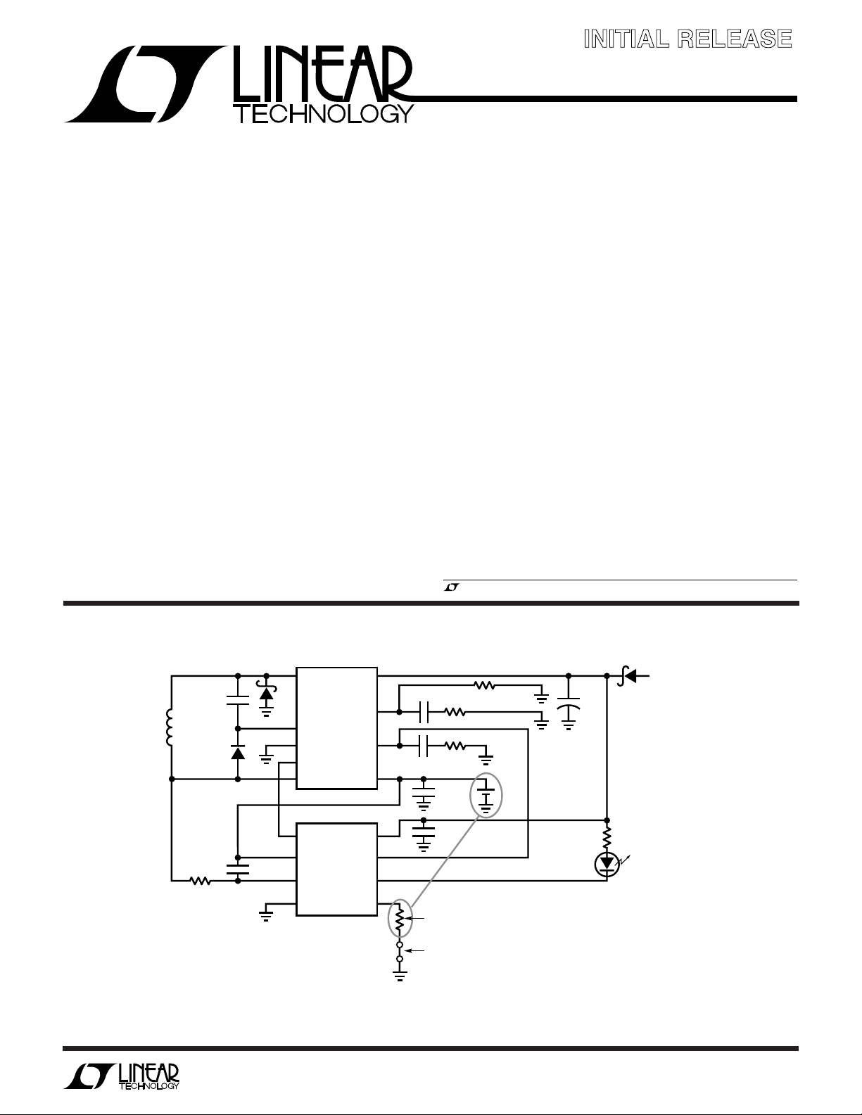
TYPICAL APPLICATION
MBRM120T3
0.22µF
L1**
10µH
MMBD914L
200Ω
* TOKIN OR MARCON SURFACE MOUNT
** COILTRONICS TP3-100, 10µH, 2.2mm HEIGHT
(0.8A CHARGING CURRENT)
COILTRONICS TP1 SERIES, 10µH, 1.8mm
HEIGHT (<0.5A CHARGING CURRENT)
*** PANASONIC EEFCD1B220
†
LUMEX SML-LX0805GW-TR
1µF
U
SW
LT1510-5
BOOST
GND
OVP
SENSE
1
OVP
2
BAT
LTC1729-4.2
3
SENSE
4
GND
Figure 1. 500kHz Li-Ion Cell Phone Charger (0.8A)
V
PROG
BAT
V
STATUS
NTC
CC
1µF
V
C
0.1µF
8
CC
7
V
C
6
5
10k NTC THERMISTOR, NTHS1206N02 VISHAY/DALE
NOTE: EITHER A THERMISTOR OR 10k RESISTOR MUST BE PRESENT
OPTION: TIE RESISTOR TO STATUS FOR
CHARGE TERMINATION AT
LOW CHARGING CURRENT
300Ω
C
OUT
22µF
0.1µF
6.19k
1k
+
***
4.2V
+
MBRM120T3
CIN*
10µF
1729 F01
1.4k
†
D1
CHARGE STATUS
INPUT POWER
8.2V TO 20V
Information furnished by Linear Technology Corporation is believed to be accurate and reliable.
However, no responsibility is assumed for its use. Linear Technology Corporation makes no representation that the interconnection of its circuits as described herein will not infringe on existing patent rights.
1
LTC1729 Series
WW
W
ABSOLUTE MAXIMUM RATINGS
U
(Note 1)
VCC......................................................................... 30V
SENSE, V
, NTC .................................... –0.3V to 15V
BAT
VC............................................................. –0.3V to 15V
OVP ............................................................ –0.3V to 5V
U
W
U
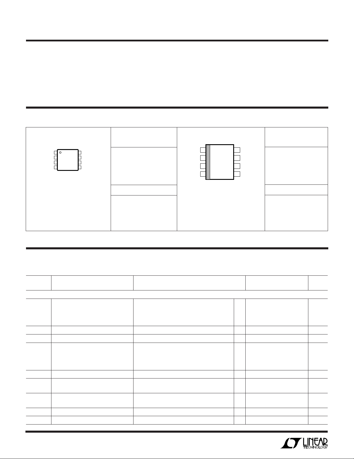
PACKAGE/ORDER INFORMATION
ORDER PART
TOP VIEW
OVP
1
BAT
2
SENSE
3
GND
4
MS8 PACKAGE
8-LEAD PLASTIC MSOP
T
= 150°C, θJA = 200°C/W
JMAX
8
V
7
V
6
STATUS
5
NTC
CC
C
NUMBER
LTC1729CMS8-4.1
LTC1729CMS8-4.2
LTC1729CMS8-8.2
LTC1729CMS8-8.4
MS8 PART MARKING
LTLY
LTJH
LTLZ
LTJG
STATUS .................................................... –0.3V to 30V
Operating Temperature Range .................... 0°C to 70°C
Storage Temperature Range ................ –65°C to 150°C
Lead Temperature (Soldering, 10 sec)................. 300°C
ORDER PART
1
OVP
BAT
2
SENSE
3
GND
4
8-LEAD PLASTIC SO
T
= 150°C, θJA = 150°C/W
JMAX
TOP VIEW
S8 PACKAGE
8
7
6
5
V
CC
V
C
STATUS
NTC
NUMBER
LTC1729CS8-4.1
LTC1729CS8-4.2
LTC1729CS8-8.2
LTC1729CS8-8.4
S8 PART MARKING
172941
172942
172982
172984
Consult factory for Industrial and Military grade parts.
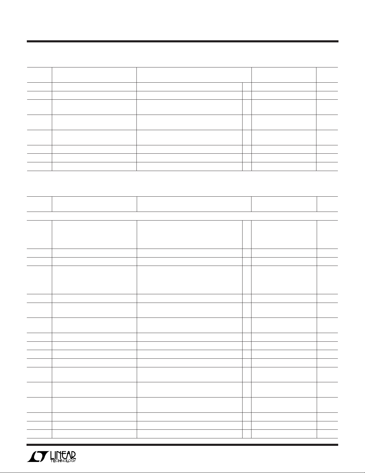
ELECTRICAL CHARACTERISTICS
The ● denotes specifications which apply over the full operating temperature range, otherwise specifications are TA = 25°C, VIN = 8V.
LTC1729-4.1/LTC1729-4.2
SYMBOL PARAMETER CONDITIONS MIN TYP MAX UNITS
DC CHARACTERISTICS
I
VIN
V
LKOH
V
LKOL
I
VBAT
V
CLAMP
V
MAX
V
MIN
I
SENSE
V
C10
VCC Supply Current VIN = 5V (Below UVLO) ● 1512 µA
V
= 8V, 200µA Pull-Up on V
IN
= 8V, V
V
IN
VIN = 8V, V
VIN Undervoltage Lockout High ● 5.5 6.5 7.5 V
VIN Undervoltage Lockout Low ● 5.0 6.0 7.0 V
V
Current VIN = 5V (Below UVLO), V
BAT
V
Clamp No Bat (External 200µA Pull-Up on V
BAT
High V
Low V
SENSE Pin Current Charge State, V
SENSE Pin C/10 Offset Charge State, V
Threshold High Going Threshold ● 4.25 4.51 4.75 V
BAT
Threshold High Going Threshold ● 2.55 2.7 2.85 V
BAT
= 8V, V
V
IN
= 8V, V
V
IN
VIN = 8V, V
Low Going Threshold ● 4.25 4.50 4.75 V
Low Going Threshold ● 2.45 2.6 2.75 V
= 2.5V Trickle 10 17 21 mA
BAT
= 3.5V Charge ● 0.5 3.0 5.0 mA
BAT
= 4.25V No Bat ● 40 73 120 µA
BAT
= 2.5V Trickle – 19 –16 –9.5 mA
BAT
= 3.5V Charge ● –2.7 – 1.3 – 0.5 mA
BAT
= 3V ● 85 100 115 µA
SENSE
= (V
C10
BAT
(4.5V) No Bat ● 1.0 1.4 2.0 mA
BAT
= 4.2V ● –1 –0.1 1 µA
BAT
) ● 4.25 4.5 4.75 V
BAT
– V
) ● ±1 ±2.5 mV
SENSE
2
LTC1729 Series
ELECTRICAL CHARACTERISTICS
The ● denotes specifications which apply over the full operating temperature range, otherwise specifications are TA = 25°C, VIN = 8V.
LTC1729-4.1/LTC1729-4.2
SYMBOL PARAMETER CONDITIONS MIN TYP MAX UNITS
I
NTC
V
NTC-RESET
V
NTC-HOT
V
NTC-COLD
V
OVP
V
OL-ST
V
OL-VC
I
SOFT
The ● denotes specifications which apply over the full operating temperature range, otherwise specifications are TA = 25°C,
VIN = 12V
SYMBOL PARAMETER CONDITIONS MIN TYP MAX UNITS
DC CHARACTERISTICS
I
VIN
V
LKOH
V
LKOL
I
VBAT
V
CLAMP
V
MAX
V
MIN
I
SENSE
V
C10
I
NTC
V
NTC-RESET
V
NTC-HOT
V
NTC-COLD
V
OVP
V
OL-ST
V
OL-VC
I
SOFT
NTC Pin Current V
= 1V ● 90 100 110 µA
NTC
Thermistor Pin Reset Threshold ● 0.160 0.206 0.240 V
Thermistor Pin Hot Hold Threshold High Going Threshold ● 0.460 0.486 0.510 V
Low Going Threshold ● 0.380 0.405 0.430 V
Thermistor Pin Cold Hold Threshold High Going Threshold ● 2.70 2.79 2.90 V
Low Going Threshold ● 2.10 2.23 2.35 V
OVP Pin Voltage V
= 4.1V or V
BAT
= 4.2V ● 2.455 2.465 2.475 V
BAT
2.460 2.465 2.470 V
Output Low Voltage-STATUS Pin IO = 3mA ● 0.5 0.9 1.2 V
Output Low Voltage-VC Pin IO = 1mA ● 0.35 0.6 0.75 V
Status Soft Pull-Down Current V
= 4.5V ● 40 50 65 µA
STATUS
LTC1729-8.2/LTC1729-8.4
VCC Supply Current VIN = 9V (Below UVLO) ● 1612 µA
V
= 12V, 200µA Pull-Up on V
IN
= 12V, V
V
IN
VIN = 12V, V
= 5V Trickle 10 17 21 mA
BAT
= 7V Charge ● 0.5 3.0 5.0 mA
BAT
(9V) No Bat ● 1.0 1.4 2.0 mA
BAT
VIN Undervoltage Lockout High ● 9.5 10.4 11.4 V
VIN Undervoltage Lockout Low ● 8.5 9.6 10.5 V
V
Current VIN = 9V (Below UVLO), V
BAT
V
Clamp No Bat (External 200µA Pull-Up on V
BAT
High V
Threshold High Going Threshold ● 8.5 9.013 9.5 V
BAT
= 12V, V
V
IN
= 12V, V
V
IN
VIN = 12V, V
= 8.5V No Bat ● 60 95 140 µA
BAT
= 5V Trickle – 19 – 16 –9.5 mA
BAT
= 7V Charge ● –2.7 – 1.3 – 0.5 mA
BAT
= 8.4V ● –1 –0.1 1 µA
BAT
) ● 8.5 9 9.5 V
BAT
Low Going Threshold ● 8.5 9 9.5 V
Low V
Threshold High Going Threshold ● 5.1 5.4 5.7 V
BAT
Low Going Threshold ● 4.9 5.2 5.5 V
SENSE Pin Current Charge State, V
SENSE Pin C/10 Offset Charge State, V
NTC Pin Current V
= 1V ● 90 100 110 µA
NTC
= 7V ● 85 100 115 µA
SENSE
= (V
C10
BAT
– V
) ● ±1 ±2.5 mV
SENSE
Thermistor Pin Reset Threshold ● 0.160 0.206 0.240 V
Thermistor Pin Hot Hold Threshold High Going Threshold ● 0.460 0.486 0.510 V
Low Going Threshold ● 0.380 0.405 0.430 V
Thermistor Pin Cold Hold Threshold High Going Threshold ● 2.70 2.79 2.90 V
Low Going Threshold ● 2.10 2.23 2.35 V
OVP Pin Voltage V
= 8.2V or V
BAT
= 8.4V ● 2.455 2.465 2.475 V
BAT
2.460 2.465 2.470 V
Output Low Voltage-STATUS Pin IO = 3mA ● 0.5 0.9 1.2 V
Output Low Voltage-VC Pin IO = 1mA ● 0.35 0.6 0.75 V
Status Soft Pull-Down Current V
= 4.5V ● 40 50 65 µA
STATUS
3
LTC1729 Series
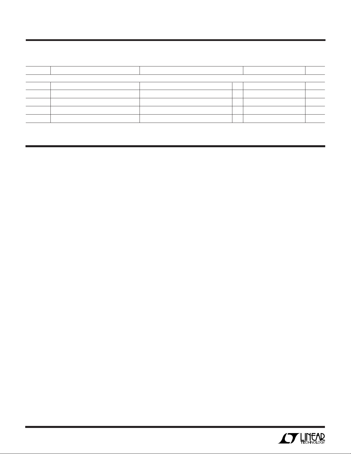
ELECTRICAL CHARACTERISTICS
The ● denotes specifications which apply over the full operating temperature range, otherwise specifications are TA = 25°C. (Note 2)
SYMBOL PARAMETER CONDITIONS MIN TYP MAX UNITS
AC CHARACTERISTICS
TIMER1 Timer for Trickle-Charge Preconditioning ● 0.869 1 1.305 Hr
TIMER2 Timer for Charging ● 2.61 3 3.55 Hr
TIMER3 Timer for V
TIMER4 Timer for V
T
OSC
Oscillator Period ● 6.66 7.63 9.09 µs
Filter ● 0.764 0.859 1.043 sec
MAX
Filter ● 3.055 3.5 4.17 sec
C/10
Note 1: Absolute Maximum Ratings are those values beyond which the life
of a device may be impaired.
UUU
PIN FUNCTIONS
OVP (Pin 1): Output from an Internal Precision Resistor
Divider Used as a Voltage Feedback Monitor for ConstantVoltage Mode Charging.
BAT (Pin 2): Input to Battery Monitor Circuits and OVP
Resistor Divider. The battery monitor circuits activate
trickle charge preconditioning, battery present detection
and C/10 current detection. This pin is in a high impedance
state when VCC is below the undervoltage lockout threshold. During trickle charge preconditioning and charging
the BAT pin sources 16mA and 1.3mA respectively. The
current sources are clamped from driving the BAT pin
above 4.5V/cell with an internal pull-down transistor.
In the No Bat, Done and Pause states or the Hold and Reset
modes, the current sources are turned off, leaving only the
55k OVP divider as a load on the BAT pin. Most chargers
have a 200µA current source that will compensate for this
50µA to 80µA load.
SENSE (Pin 3): Input to C/10 Current Detection Circuit.
This pin sinks 100µA during the Charge state which is used
to program the C/10 current threshold.
GND (Pin 4): Ground.
NTC (Pin 5): Input to the NTC Thermistor Monitoring
Circuits. When the voltage on this pin is above 2.79V
(cold) or below 0.405V (hot), the state machine is locked
in the present state and the timer is stopped. This is called
the Hold mode. While in the Hold mode, the charger is
turned off via the VC pin and the current sources on BAT
and SENSE pins are turned off. The STATUS pin is not
affected.
Note 2: VIN = 8V for LTC1729-4.1/LTC1729-4.2; VIN = 12V for
LTC1729-8.2/LTC1729-8.4
If the NTC pin is below 0.2V, the state machine is forced
in the reset mode with all the timers cleared to zero. The
current sources on the BAT pin and SENSE pin are
disabled leaving the 55k OVP divider. The STATUS pin is
pulled low in the Reset mode.
There is a 100µA current source on the NTC pin to bias the
NTC thermistor. This current source is active while the V
CC
is greater than the undervoltage lockout threshold.
STATUS (Pin 6): Open-Drain Output for C/10 Charge
Termination Detection Circuit. When in the Charge state,
this pin is pulled low. Once the charge current drops below
the C/10 current threshold for three seconds, the pulldown transistor is disabled, and a 50µA pull-down current
sink remains activated until the 1- or 3-hour time-out or
the battery or wall adapter is removed.
VC (Pin 7): Open-Drain Output for turning off the charger.
When this pin is open circuit, the charger is active.
Normally this pin allows the charger to be active for three
hours.
VCC (Pin 8): Input Supply. For 4.1V or 4.2V single cell
operation, VCC should be between 8V and 28V with the IC
turning off when VCC drops below 6V. For 2-cell applications, the undervoltage lockout is 10.4V with a minimum
VCC of 12V. Removing the wall adapter will trigger an
undervoltage lockout and put the part in a high impedance
condition. When the supply is connected, the part is
initialized in the Reset mode with the state machine forced
in the Charge state with all the timers set to zero.
4
 Loading...