

advertisement
Low Distortion, Low Noise Differential Amplifier Drives High Speed
ADCs in Demanding Communications Transceivers
Design Note 366
Cheng-Wei Pei
Introduction
Today’s communications transceivers operate at much
higher frequencies and wider bandwidths than those of
the past. Combining this with higher resolution requirements, transceiver design can become daunting. For
engineers designing these systems, small noise and
distortion budgets leave little flexibility when choosing
system components.
®
The LT
1993-x is designed to meet the demanding requirements of communications transceiver applications. It can
be used as a differential ADC driver or as a general-purpose
differential gain block. For single-ended systems, the
LT1993-x can replace a transformer in performing singleended to differential conversion without sacrificing noise
or distortion performance.
R
F
R
–INA
14
–INB
13
+INA
16
+INB
15
G
R
G
R
G
R
G
3 10 1 11 1294
V
CC
1993-2: RF = 200Ω
= 200Ω
R
G
BW = 800MHz
–
A
+
R
F
R
F
+
C
–
+
B
–
R
F
ENABLE
= 200Ω
1993-4: R
F
= 100Ω
R
G
BW = 900MHz
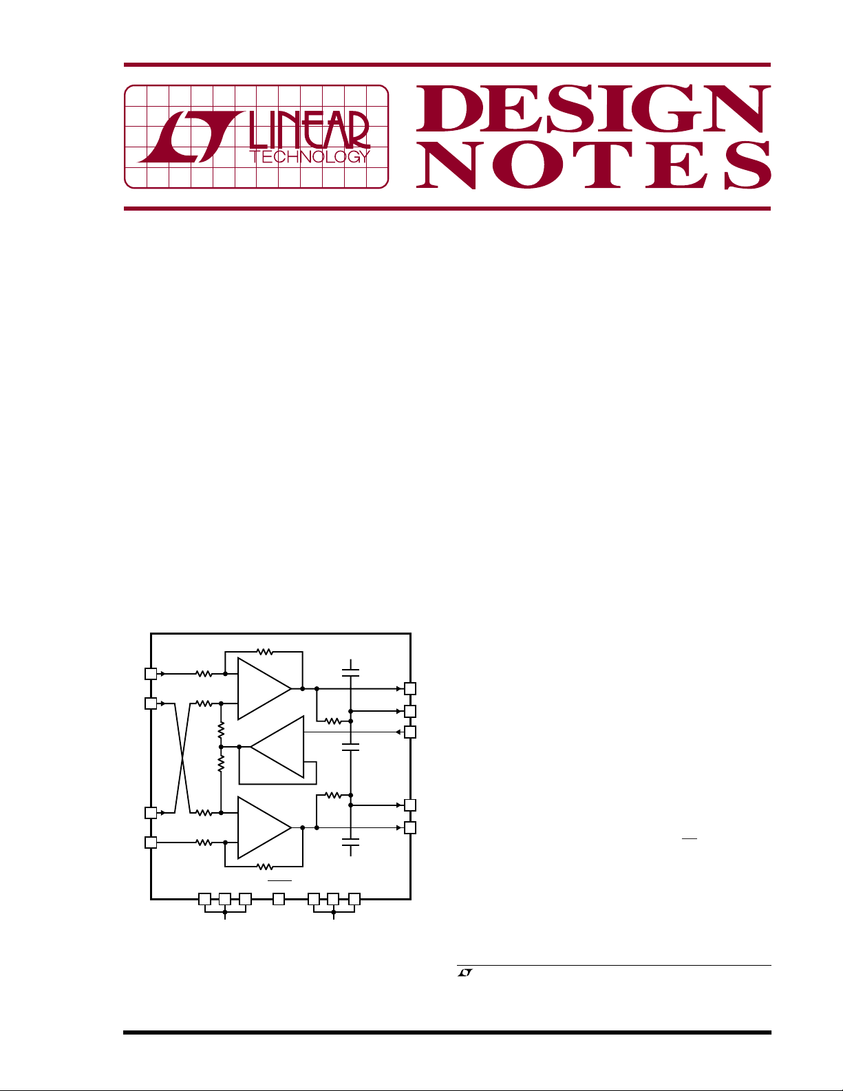
Figure 1. Block Diagram of the LT1993-x and the Differences Between the Gain Options. Input Impedance Is 200Ω
for the 6dB Version and 100Ω for the Other Two Versions
12pF
25Ω
12pF
25Ω
12pF
V
EE
1993-10: R
V
EE
+OUTFILTERED
–OUTFILTERED
V
EE
= 500Ω
F
= 100Ω
R
G
BW = 700MHz
+OUT
V
OCM
–OUT
5
6
2
7
8
DN366 F01
LT1993-x Features
The LT1993-x is a fully differential input and output amplifier with up to 7GHz of gain-bandwidth product and an
impressive feature set. There are three fixed-gain options
with internal matched resistors: gain of 2 (6dB), gain of 4
(12dB) and gain of 10 (20dB). The LT1993-x is DC-coupled,
precluding the need for DC blocking capacitors on the
inputs and outputs. The output common mode voltage is
independently controlled with an external pin, allowing
optimal bias conditions for the ADC inputs. The LT1993-x
features two sets of differential outputs: a normal output
and a filtered output. The output filter eliminates additional
filtering in many applications, but if necessary, additional
filtering can be achieved with a few external components.
Figure 1 shows a block diagram of the LT1993-x.
High Speed ADC Driving
One of the more challenging tasks in a modern communications transceiver is driving the analog-to-digital converter (ADC). Today’s converters sample data at tens to
hundreds of Megahertz with up to 16 bits of resolution. With
each sample cycle, the switching of the internal ADC sample
and hold injects charge into the output of the driver which
must absorb the charge and settle its output before the next
sample is taken. This charge injection is inherent in nearly
all high speed, high resolution ADC topologies and must
be considered when choosing a suitable driver.
The LT1993-x was designed specifically to drive high speed
ADCs to their full potential. With a 3.8nV/√Hz voltage noise
specification and –70dBc of harmonic distortion at 70MHz
(2V
differential output), the LT1993-x meets and
P-P
exceeds the requirements for driving high resolution high
speed ADCs. Figure 2 shows an FFT of sampled data taken
on a 70MHz input signal with the LT1993-2 driving an
®
LTC
2249 sampling at 80Msps.
, LTC and LT are registered trademarks of Linear Technology Corporation.
All other trademarks are the property of their respective owners.
06/05/366
0
–10
–20
–30
–40
–50
–60
–70
–80
AMPLITUDE (dBFS)
–90
–100
–110
–120
5
0
10
8192 POINT FFT
= 70MHz
f
IN
= 2V
V
IN
DIFFERENTIAL
HD2 = –74dBc
HD3 = –70dBc
20
25
15
FREQUENCY (MHz)
P-P
40
30
35
DN366 F02
Figure 2. FFT Data Taken Using the LT1993-2 and the
LTC2249 ADC Sampling at 80Msps. The Second Harmonic
Is at –74dBc and the Third Harmonic Is at –70dBc
0
32768 POINT FFT
–10
TONE CENTER FREQUENCIES AT
62.5MHz, 67.5MHz, 72.5MHz, 77.5MHz
–20
–30
–40
–50
–60
–70
–80
AMPLITUDE (dBFS)
–90
–100
–110
5MHz
63dB
60
FREQUENCY (MHz)
5MHz
63dB
80757065
DN366 F04
Figure 4. FFT Data Taken from the Output of the LTC2255
ADC. The Low IMD of the LT1993-2 Preserves the Signalto-Noise Ratio of the WCDMA Channels
WCDMA Amplifier and ADC Driver
Wideband CDMA transceivers often use direct IF sampling,
meaning that the ADC samples signals with a 70MHz center frequency and 5MHz of bandwidth per channel. Up to
4 WCDMA channels are transmitted simultaneously,
spaced closely in frequency. This places difficult
intermodulation distortion (IMD) and noise requirements
on the components in the transceiver, since both raise the
noise floor in the closely spaced adjacent channels. The
LT1993-2 boasts an exceptional –70dBc IMD and low
noise, allowing 63dBc of adjacent channel leakage ratio
(ACLR) for WCDMA signals. This figure exceeds most
WCDMA manufacturers’ ACLR specifications.
Figure 3 shows the LT1993-2 driving a LTC2255 14-bit ADC
with a 70MHz, 4-channel WCDMA signal. On the output of
the LT1993-2 is a simple LC bandpass filter that adds
additional out-of-band filtering. Figure 4 shows the FFT data
from the LTC2255, demonstrating the good ACLR possible
LT1993-2
V
V
OCM
+
–
5V
–OUT
–OUTFILT
+OUTFILT
+OUT
EE
SET V
ADC PERFORMANCE
70MHz
IF IN
1:4
Z-RATIO
•
•
MINI-CIRCUITS
TCM4-19
0.1mF
–INB
–INA
0.1mF
+INB
+INA
ENABLE
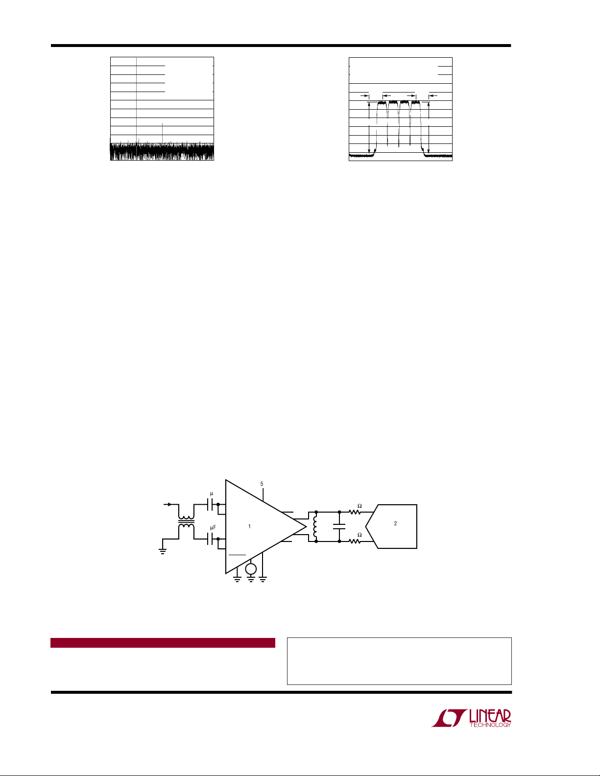
with the LT1993-2. The small aberrations on the sides of
the WCDMA signals are artifacts of a noisy signal generator, whose output was bandpass filtered prior to reaching
the LT1993-2.
Conclusion
The LT1993-x is a flexible, cost saving, and easy-to-use
differential amplifier and ADC driver that ensures the best
performance in high speed communications transceiver
applications. Besides the low noise, low distortion and high
speed, the LT1993-x also saves space with its 0.8mm tall
3mm × 3mm QFN package. Minimal support circuitry is
required to operate the LT1993-x under most conditions
and output lowpass filtering is included. Three different gain
options increase the flexibility of system design and help
reduce the gain requirements of noisier system components. The LT1993-x can simplify transceiver designs,
reduce component count and reduce product time-tomarket.
12.1
W
–
AIN
LTC2255
AIN
f
SAMPLE
ADC
+
= 96.12MHz
DN366 F03
W
FOR OPTIMAL
OCM
52.3pF82nH
12.1
Figure 3. The LT1993-2 Driving an LTC2255 ADC Sampling at 96.12Msps with a 70MHz,
4-Channel WCDMA Signal. The Simple LC Output Network Provides Out-of-Band Filtering
Data Sheet Download
http://www.linear.com
Linear Technology Corporation
1630 McCarthy Blvd., Milpitas, CA 95035-7417
(408) 432-1900 ● FAX: (408) 434-0507 ● www.linear.com
For applications help,
call (408) 432-1900, Ext. 2156
dn366f LT/TP 0605 409K • PRINTED IN THE USA
© LINEAR TECHNOLOGY CORPORATION 2005
 Loading...