

Page 1

LT1789-1/LT1789-10
Micropower,
Single Supply Rail-to-Rail
Output Instrumentation Amplifi ers
FEATURES
n
Micropower: 95μA Supply Current Max
n
Low Input Offset Voltage: 100μV Max
n
Low Input Offset Voltage Drift: 0.5μV/°C Max
n
Single Gain Set Resistor:
G = 1 to 1000 (LT1789-1)
G = 10 to 1000 (LT1789-10)
n
Inputs Common Mode to V
n
Wide Supply Range: 2.2V to 36V Total Supply
n
CMRR at G = 10: 96dB Min
n
Gain Error: G = 10, 0.25% Max
n
Gain Nonlinearity: G = 10, 40ppm Max
n
Input Bias Current: 40nA Max
n
PSRR at G = 10: 100dB Min
n
1kHz Voltage Noise: 48nV/√Hz
n
0.1Hz to 10Hz Noise: 1.5μV
–
P-P
APPLICATIONS
n
Portable Instrumentation
n
Bridge Amplifi ers
n
Strain Gauge Amplifi ers
n
Thermocouple Amplifi ers
n
Differential to Single-Ended Converters
n
Medical Instrumentation
DESCRIPTION
The LT®1789-1/LT1789-10 are micropower, precision
instrumentation amplifi ers that are optimized for single
supply operation from 2.2V to 36V. The quiescent current
is 95μA max, the inputs common mode to ground and the
output swings within 110mV of ground. The gain is set
with a single external resistor for a gain range of 1 to 1000
for the LT1789-1 and 10 to 1000 for the LT1789-10.
The high accuracy of the LT1789-1 (40ppm maximum nonlinearity and 0.25% max gain error) is unmatched by other
micropower instrumentation amplifi ers. The LT1789-10
maximizes both the input common mode range and dynamic
output range when an amplifi cation of 10 or greater is required,
allowing precise signal processing where other instrumentation amplifi ers fail to operate. The LT1789-1/LT1789-10 are
laser trimmed for very low input offset voltage, low input
offset voltage drift, high CMRR and high PSRR. The output
can handle capacitive loads up to 400pF (LT1789-1), 1000pF
(LT1789-10) in any gain confi guration while the inputs are
ESD protected up to 10kV (human body).
The LT1789-1/LT1789-10 are offered in the 8-pin SO
package, requiring signifi cantly less PC board area than
discrete multi op amp and resistor designs.
L, LT, LTC and LTM are registered trademarks of Linear Technology Corporation. All other
trademarks are the property of their respective owners.
TYPICAL APPLICATION
90.9k
V
IN
VS = 3.3V TO 32V
V
IN
=
I
LOAD
R
• 10
SENSE
= 1A PER VOLT AS SHOWN
RISE TIME ≈ 250μs, 10% TO 90%,
1A TO 2A OUTPUT STEP INTO 0.25Ω LOAD
0.5A to 4A Voltage Controlled Current Source
C1
4700pF
V
R1
R2
10k
S
–
7
2
4
R4
10k
C2
3300pF
6
5
LT1636
+
3
C3
0.1μF
R3
100Ω
V
S
7
6
LT1789-1
REF
5
4
120Ω
8k
3
+
8
1
–
2
V
S
TIP127*
* ENSURE ADEQUATE POWER
DISSIPATION CAPABILITY AT
HIGHER VOLTAGES,
3
CURRENTS AND DUTY CYCLES
1
R
*
SENSE
0.1Ω
I
LOAD
2
4
R
*
LOAD
1789 TA01
1789fb
1
Page 2

LT1789-1/LT1789-10
PIN CONFIGURATION ABSOLUTE MAXIMUM RATINGS
(Note 1)
Supply Voltage (V+ to V–)..........................................36V
Input Differential Voltage...........................................36V
Input Current (Note 3) ..........................................±20mA
Output Short-Circuit Duration .......................... Indefi nite
Operating Temperature Range.................. –40°C to 85°C
Specifi ed Temperature Range (Note 4)
LT1789C-1, LT1789C-10 ......................–40°C to 85°C
LT1789I-1, LT1789I-10 ....................... –40°C to 85°C
R
–IN
+IN
–V
TOP VIEW
1
G
2
3
4
S
S8 PACKAGE
8-LEAD PLASTIC SO
T
= 150°C, θJA = 190°C/W
JMAX
R
8
G
+V
7
S
OUT
6
REF
5
Storage Temperature Range ................... –65°C to 150°C
Lead Temperature (Soldering, 10 sec) ..................300°C
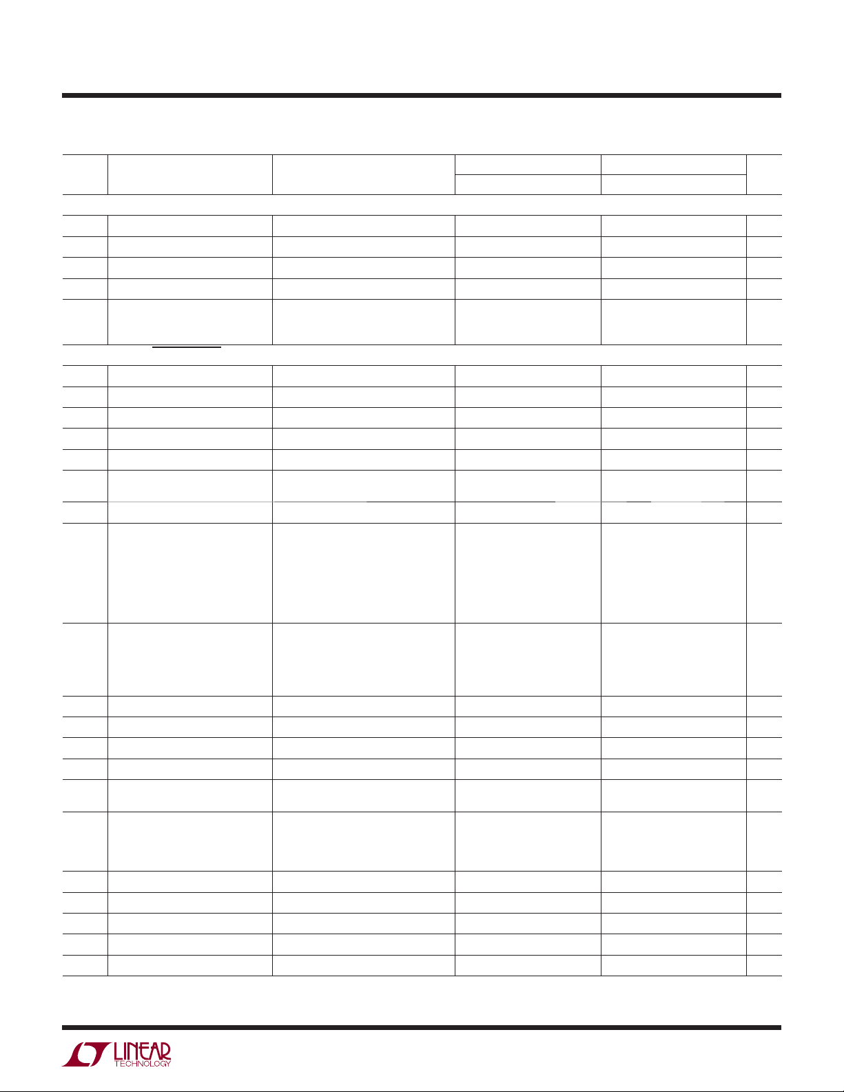
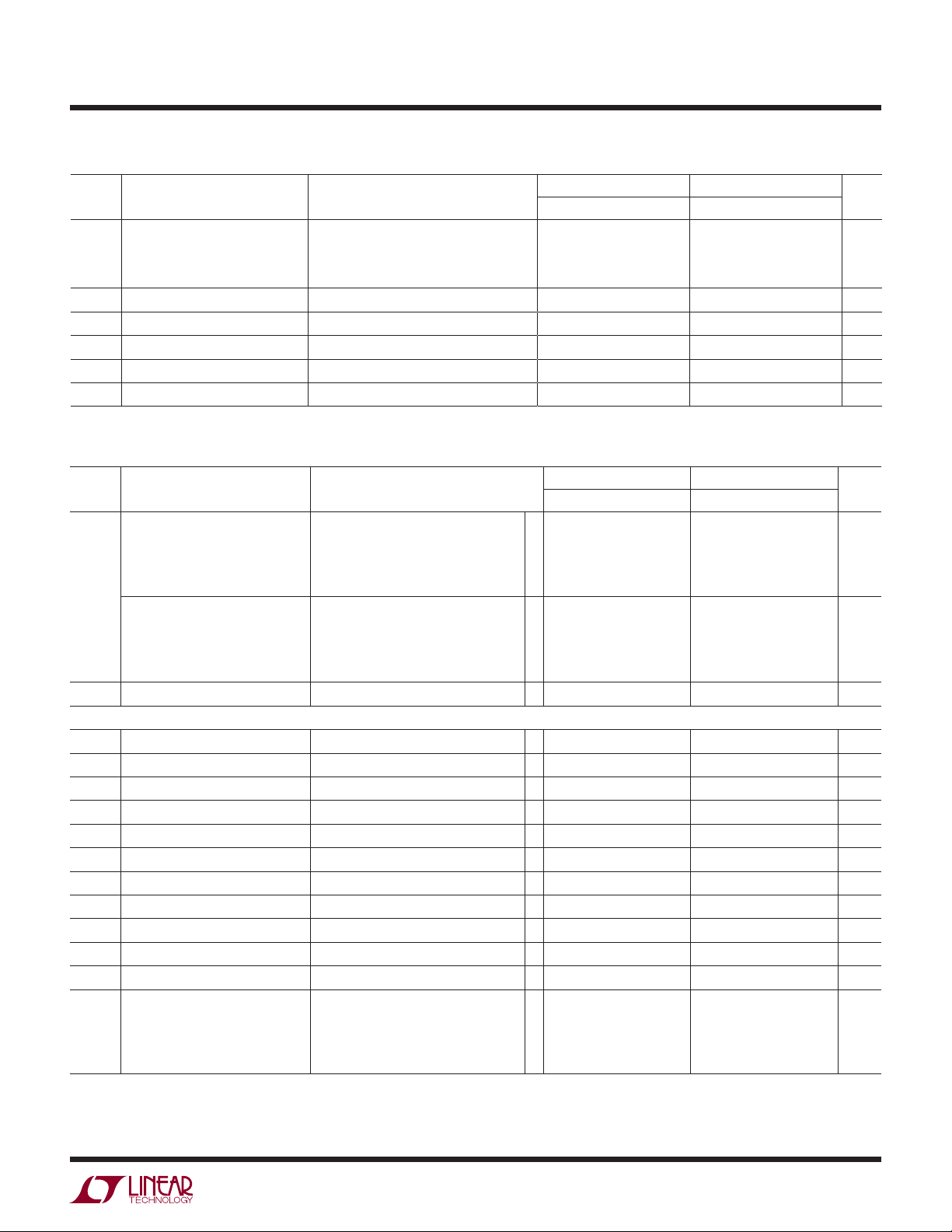
ORDER INFORMATION
LEAD FREE FINISH TAPE AND REEL PART MARKING PACKAGE DESCRIPTION TEMPERATURE RANGE
LT1789CS8-1#PBF LT1789CS8-1#TRPBF 17891 8-Lead Plastic SO –40°C to 85°C
LT1789IS8-1#PBF LT1789IS8-1#TRPBF 1789I1 8-Lead Plastic SO –40°C to 85°C
LT1789CS8-10#PBF LT1789CS8-10#TRPBF 178910 8-Lead Plastic SO –40°C to 85°C
LT1789IS8-10#PBF LT1789IS8-10#TRPBF 789I10 8-Lead Plastic SO –40°C to 85°C
LEAD BASED FINISH TAPE AND REEL PART MARKING PACKAGE DESCRIPTION TEMPERATURE RANGE
LT1789CS8-1 LT1789CS8-1#TR 17891 8-Lead Plastic SO –40°C to 85°C
LT1789IS8-1 LT1789IS8-1#TR 1789I1 8-Lead Plastic SO –40°C to 85°C
LT1789CS8-10 LT1789CS8-10#TR 178910 8-Lead Plastic SO –40°C to 85°C
LT1789IS8-10 LT1789IS8-10#TR 789I10 8-Lead Plastic SO –40°C to 85°C
Consult LTC Marketing for parts specifi ed with wider operating temperature ranges.
For more information on lead free part marking, go to: http://www.linear.com/leadfree/
For more information on tape and reel specifi cations, go to: http://www.linear.com/tapeandreel/
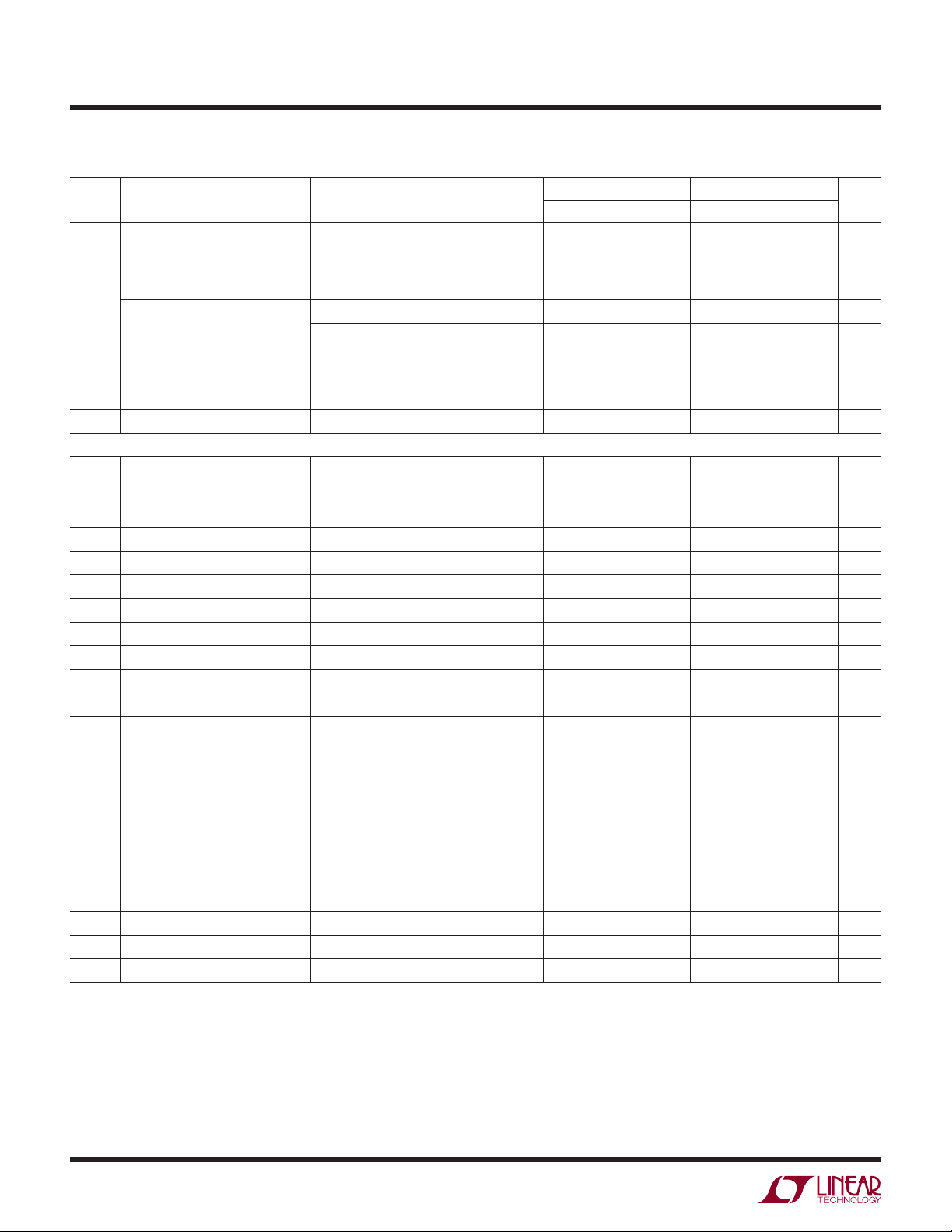
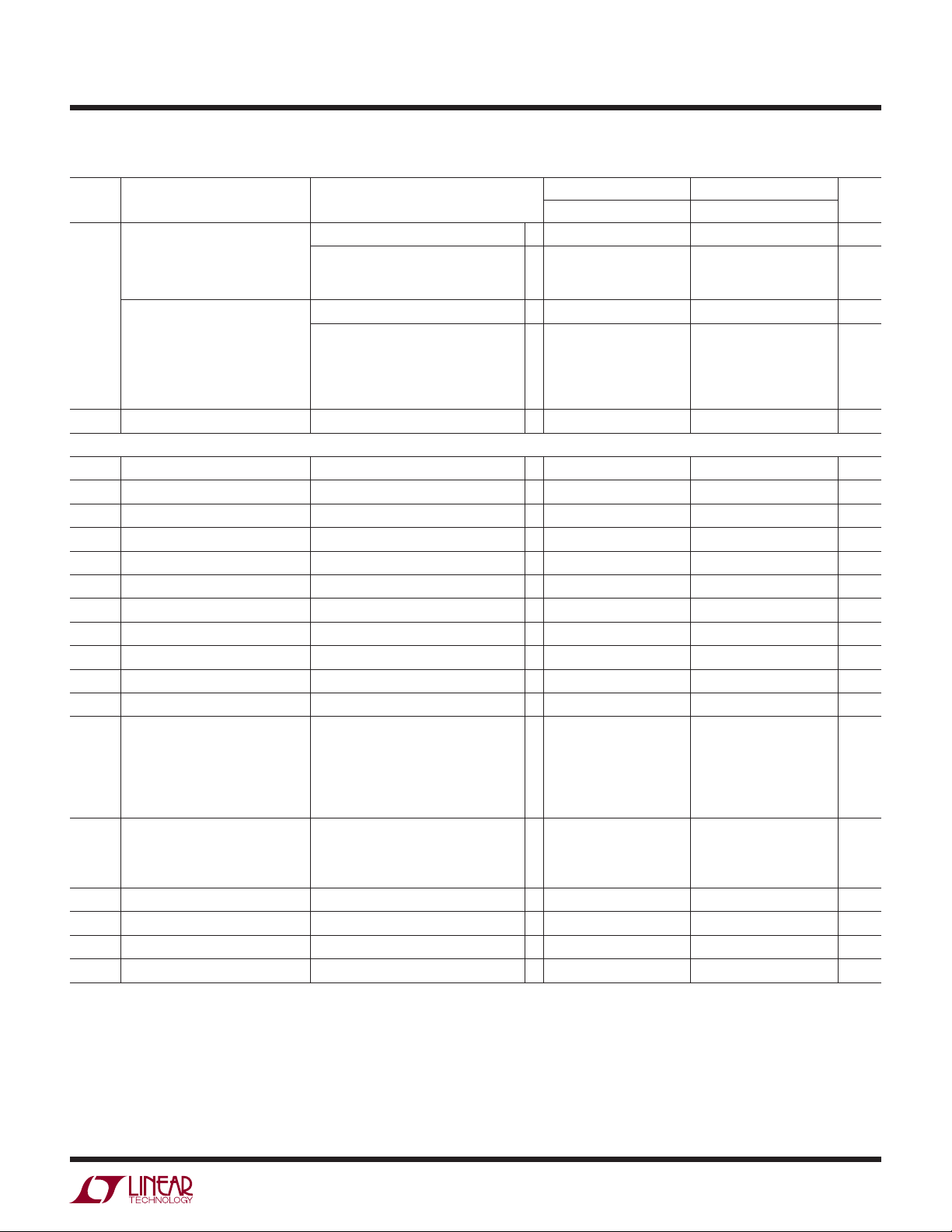
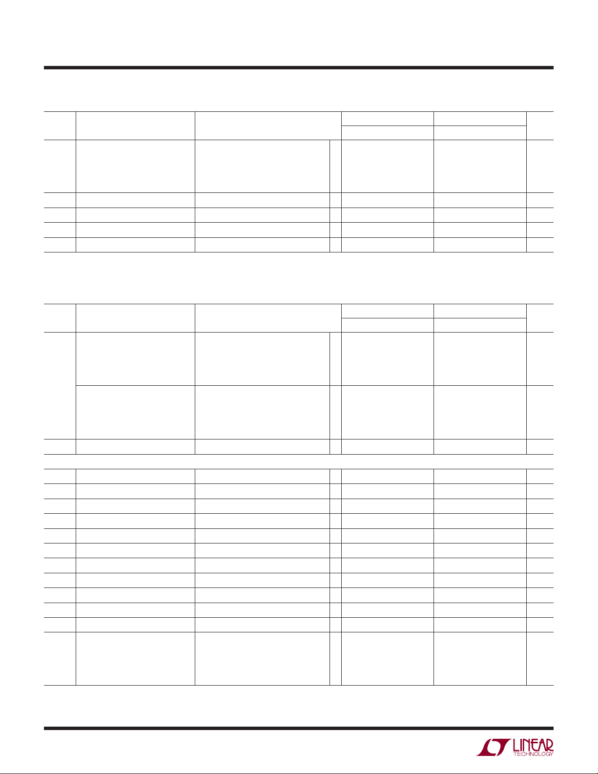
3V AND 5V ELECTRICAL CHARACTERISTICS
VS = 3V, 0V; VS = 5V, 0V; RL = 20k, VCM = V
supply, TA = 25°C, unless otherwise noted.
LT1789-1 LT1789-10
SYMBOL PARAMETER CONDITIONS
G Gain Range LT1789-1, G = 1 + (200k/R
Gain Error (Note 6) G = 1, V
Gain Nonlinearity (Note 6) G = 1, V
LT1789-10, G = 10 • [1+ (200k/R
= 0.1V to (+VS) – 1V 0.02 0.20 %
O
LT1789-1, V
LT1789-10, V
G = 10 (Note 2)
G = 100 (Note 2)
G = 1000 (Note 2)
LT1789-1, V
LT1789-10, V
(Note 8)
G = 10
G = 100
G = 1000
= 0.1V to (+VS) – 0.3V
O
= 0.2V to (+VS) – 0.3V
O
= 0.1V to (+VS) – 1V 35 100 ppm
O
= 0.1V to (+VS) – 0.3V
O
= 0.2V to 4.7V, VS = 5V
O
)
G
)]
G
1 1000
0.06
0.06
0.13
12
18
90
0.25
0.27
40
75
10 1000
0.01
0.09
0.16
15
20
100
2
REF
0.25
0.30
100
100
= half
UNITSMIN TYP MAX MIN TYP MAX
%
%
%
ppm
ppm
ppm
1789fb
Page 3
LT1789-1/LT1789-10
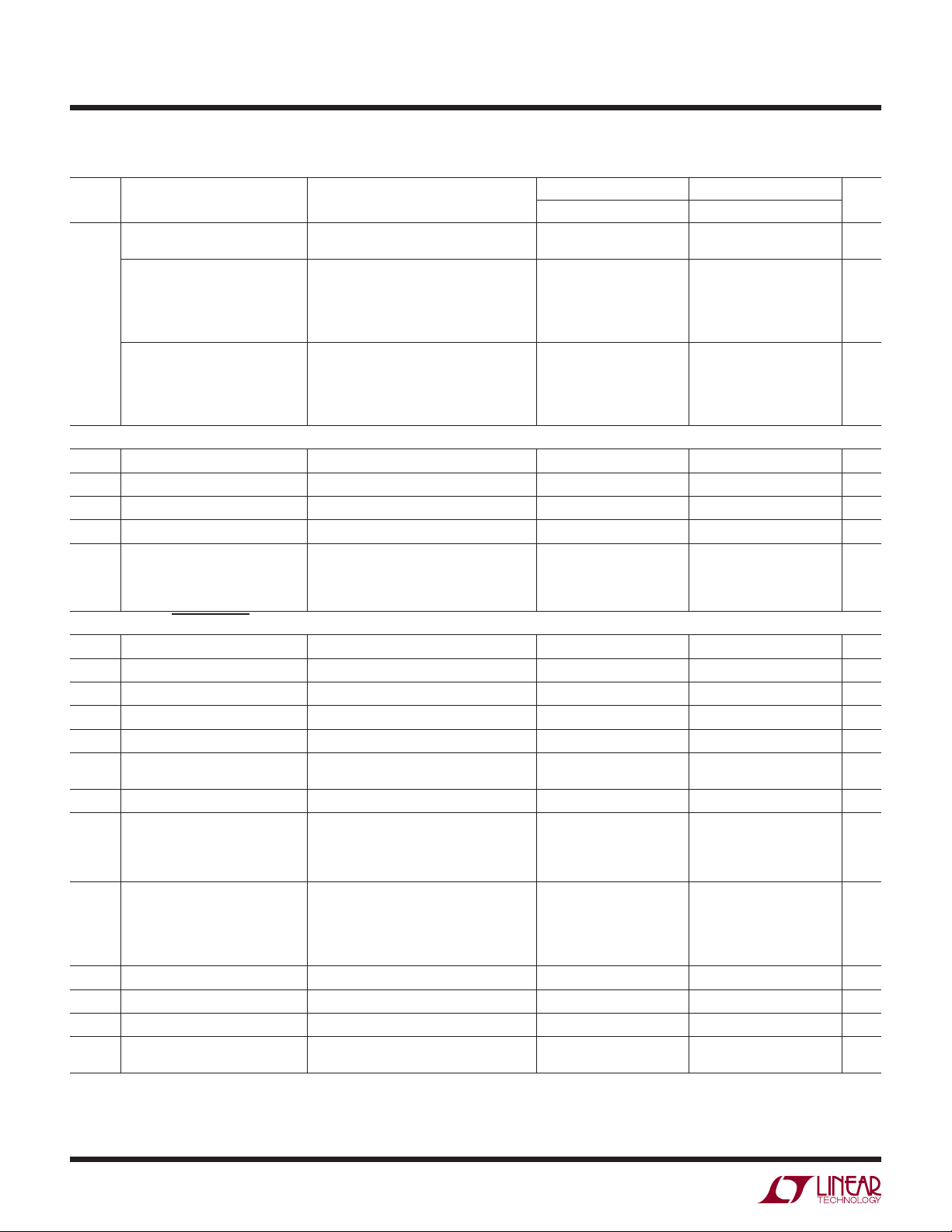
3V AND 5V ELECTRICAL CHARACTERISTICS
VS = 3V, 0V; VS = 5V, 0V; RL = 20k, VCM = V
supply, T
SYMBOL PARAMETER CONDITIONS
V
OST
V
OSI
V
OSO
I
OS
I
B
e
n
Total RTI Noise = √e
e
ni
e
no
i
n
R
IN
C
IN
V
CM
CMRR Common Mode Rejection Ratio 1k Source Imbalance (Note 6)
PSRR Power Supply Rejection Ratio V
I
S
V
OL
V
OH
I
SC
BW Bandwidth G = 1
SR Slew Rate G = 10, V
R
REFIN
I
REFIN
AV
= 25°C, unless otherwise noted.
A
LT1789-1 LT1789-10
Total Input Referred Offset Voltage V
OST
= V
OSI
+ V
OSO
/G
Input Offset Voltage G = 1000 15 100 20 160 μV
Output Offset Voltage G = 1 (LT1789-1), G =10 (LT1789-10) 150 750 650 3000 μV
Input Offset Current (Note 6) 0.2 4 0.2 4 nA
Input Bias Current (Note 6) 19 40 19 40 nA
Input Noise Voltage,
RTI (Referred to Input)
2
+ (eno/G)
ni
2
G = 1, fO = 0.1Hz to 10Hz
G = 10
G = 100, 1000
5.0
1.5
1.0
4.6
1.1
Input Noise Voltage Density, RTI fO = 1kHz (Note 7) 48 85 52 90 nV/√Hz
Output Noise Voltage Density, RTI fO = 1kHz (Note 3) 330 270 nV/√Hz
Input Noise Current fO = 0.1Hz to 10Hz 16 16 pA
Input Noise Current Density fO = 1kHz 62 62 fA/√Hz
Input Resistance VIN = 0V to (+VS) – 1V (Note 6) 0.75 1.6 0.75 1.6 GΩ
Input Capacitance Differential
Common Mode
1.6
1.6
1.6
1.6
Input Voltage Range 0 +VS – 1 0 +VS – 1.2 V
LT1789-1,VCM = 0V to (+VS) – 1V
LT1789-10, V
G = 1
G = 10
G = 100
G = 1000
= 2.5V to 12.5V, VCM = V
S
G = 1
G = 10
G = 100
G = 1000
= 0V to (+VS) – 1.2V
CM
REF
= 1V
79
96
100
100
90
100
102
102
88
106
114
114
100
113
116
116
88
98
98
94
102
102
105
113
113
109
120
120
Minimum Supply Voltage 2.2 2.5 2.2 2.5 V
Supply Current (Note 7) 67 95 67 95 μA
Output Voltage Swing LOW (Note 7) 54 100 62 110 mV
Output Voltage Swing HIGH (Note 7) +VS – 0.3 +VS – 0.19 +VS – 0.3 +VS – 0.19 V
Short-Circuit Current Short to GND
Short to +V
S
2.2
8.5
2.2
8.5
60
G = 10
G = 100
G = 1000
30
3
0.2
= 0.5V to 4.5V 0.023 0.062 V/μs
OUT
25
12
1.5
Settling Time to 0.01% 4V Step 240 190 μs
Reference Input Resistance 220 220 kΩ
Reference Input Current V
Reference Gain to Output 1 ±0.0001 1 ±0.0001
REF
= 0V 2.7 2.7 μA
REF
REF
= half
UNITSMIN TYP MAX MIN TYP MAX
μV
μV
μV
P-P
P-P
P-P
P-P
pF
pF
dB
dB
dB
dB
dB
dB
dB
dB
mA
mA
kHz
kHz
kHz
kHz
1789fb
3
Page 4
LT1789-1/LT1789-10
ELECTRICAL CHARACTERISTICS
The l denotes the specifi cations which apply over the temperature range of
0°C ≤ T
≤ 70°C. VS = 3V, 0V; VS = 5V, 0V; RL = 20k, V
A
SYMBOL PARAMETER CONDITIONS
Gain Error (Note 6) G = 1, V
O
= 0.3V to (+VS) – 0.5V
V
O
G = 10 (Note 2)
G = 100 (Note 2)
Gain Nonlinearity (Note 6) G = 1, V
O
LT1789-1, V
LT1789-10, V
(Note 8)
G = 10
G = 100
G/T Gain vs Temperature G < 1000 (Notes 2, 3)
V
V
V
V
V
V
V
I
OS
I
OS
I
B
I
B
V
OST
OSI
OSIH
OSO
OSOH
OSI
OSO
CM
Total Input Referred Offset Voltage V
Input Offset Voltage G = 1000
Input Offset Voltage Hysteresis (Notes 3, 5)
Output Offset Voltage G = 1 (LT1789-1), G = 10 (LT1789-10)
Output Offset Voltage Hysteresis (Notes 3, 5)
/T Input Offset Voltage Drift (RTI) (Note 3)
/T Output Offset Voltage Drift (Note 3)
Input Offset Current (Note 6)
/T Input Offset Current Drift
Input Bias Current (Note 6)
/T Input Bias Current Drift
Input Voltage Range
OST
= V
CMRR Common Mode Rejection Ratio 1k Source Imbalance (Note 6)
LT1789-1, VCM = 0.2V to (+VS) – 1V
LT1789-10, V
G = 1
G = 10
G = 100, 1000
V
PSRR Power Supply Rejection Ratio
= 2.5V to 12.5V, VCM = V
S
G = 1
G = 10
G = 100, 1000
Minimum Supply Voltage
I
S
V
OL
V
OH
Supply Current
Output Voltage Swing LOW (Note 7)
Output Voltage Swing HIGH (Note 7)
(Note 7)
= half supply, unless otherwise noted. (Note 4)
REF
LT1789-1 LT1789-10
= 0.3V to (+VS) – 1V
= 0.3V to (+VS) – 1V
= 0.3V to (+VS) – 0.5V
O
= 0.3V to 4.7V, VS = 5V
O
+ V
OSI
/G
OSO
= 0.2V to (+VS) – 1.5V
CM
REF
= 1V
l
l
l
l
l
l
l
l
l
l
l
l
l
l
l
l
l
l
0.2 (+VS) – 1 0.2 (+VS) – 1.5 V
l
77
l
94
l
98
l
88
l
98
l
100
l
l
l
l
+VS – 0.38 +VS – 0.38 V
UNITSMIN TYP MAX MIN TYP MAX
0.25 %
0.53
0.55
0.30
0.53
%
%
185 ppm
90
120
130
130
ppm
ppm
5 50 5 50 ppm/°C
150
190
µV
3 10 3 10 µV
950 3700 µV
50 100 300 900 µV
0.2 0.5 0.3 0.7 µV/°C
1.5
4 7 20 µV/°C
4.5 4.5 nA
3 3 pA/°C
45 45 nA
50 50
pA/°C
dB
85
96
dB
dB
dB
92
100
dB
dB
2.5 2.5 V
115 115 µA
110
120 mV
4
1789fb
Page 5
LT1789-1/LT1789-10
ELECTRICAL CHARACTERISTICS
The l denotes the specifi cations which apply over the temperature range of
–40°C ≤ T
≤ 85°C. VS = 3V, 0V; VS = 5V, 0V; RL = 20k, V
A
SYMBOL PARAMETER CONDITIONS
Gain Error (Note 6) G = 1, V
V
= 0.3V to (+VS) – 1V
O
= 0.3V to (+VS) – 0.5V
O
G = 10 (Note 2)
G = 100 (Note 2)
Gain Nonlinearity (Note 6) G = 1, V
= 0.3V to (+VS) – 1V
O
LT1789-1, V
LT1789-10, V
(Note 8)
G = 10
G = 100
G/T Gain vs Temperature G < 1000 (Notes 2, 3)
V
V
V
V
V
V
V
I
OS
I
OS
I
B
I
B
V
OST
OSI
OSIH
OSO
OSOH
OSI
OSO
CM
Total Input Referred Offset Voltage V
Input Offset Voltage G = 1000
Input Offset Voltage Hysteresis (Notes 3, 5)
Output Offset Voltage G = 1 (LT1789-1), G = 10 (LT1789-10)
Output Offset Voltage Hysteresis (Notes 3, 5)
/T Input Offset Voltage Drift (RTI) (Note 3)
/T Output Offset Voltage Drift (Note 3)
Input Offset Current (Note 6)
/T Input Offset Current Drift
Input Bias Current (Note 6)
/T Input Bias Current Drift
Input Voltage Range
OST
= V
OSI
CMRR Common Mode Rejection Ratio 1k Source Imbalance (Note 6)
LT1789-1, VCM = 0.2V to (+VS) – 1V
LT1789-10, V
G = 1
G = 10
G = 100, 1000
V
PSRR Power Supply Rejection Ratio
= 2.5V to 12.5V, VCM = V
S
G = 1
G = 10
G = 100, 1000
Minimum Supply Voltage
I
S
V
OL
V
OH
Supply Current
Output Voltage Swing LOW (Note 7)
Output Voltage Swing HIGH (Note 7)
(Note 7)
= half supply, unless otherwise noted. (Note 4)
REF
LT1789-1 LT1789-10
l
l
l
l
= 0.3V to (+VS) – 0.5V
O
= 0.3V to 4.7V, VS = 5V
O
l
l
l
+ V
/G
OSO
l
l
l
= 0.2V to (+VS) – 1.5V
CM
= 1V
REF
l
l
l
l
l
l
l
l
0.2 +VS – 1 0.2 +VS – 1.5 V
l
75
l
92
l
96
l
86
l
96
l
98
l
l
l
l
+VS – 0.40 +VS – 0.40 V
50 100 300 900 µV
0.2 0.5 0.3 0.7 µV/°C
1.5
50 50
UNITSMIN TYP MAX MIN TYP MAX
0.30 %
0.57
0.59
0.35
0.62
%
%
250 ppm
105
160
150
170
ppm
ppm
5 50 5 50 ppm/°C
175
205
µV
3 10 3 10 µV
1050 4000 µV
4 7 20 µV/°C
55nA
3 3 pA/°C
50 50 nA
pA/°C
dB
84
94
dB
dB
dB
90
98
dB
dB
2.5 2.5 V
125 125 µA
120
130 mV
1789fb
5
Page 6
LT1789-1/LT1789-10
ELECTRICAL CHARACTERISTICS
= ±15V, RL = 20k, VCM = V
V
S
SYMBOL PARAMETER CONDITIONS
G Gain Range LT1789-1, G = 1 + (200k/R
Gain Error V
Gain Nonlinearity V
V
OST
V
OSI
V
OSO
I
OS
I
B
e
n
Total RTI Noise = √e
e
ni
e
no
i
n
Total Input Referred Offset Voltage V
Input Offset Voltage G = 1000 30 235 30 295 μV
Output Offset Voltage G = 1 (LT1789-1), G =10 (LT1789-10) 0.2 1 0.6 3.3 mV
Input Offset Current 0.2 4 0.2 4 nA
Input Bias Current 17 40 17 40 nA
Input Noise Voltage, RTI fO = 0.1Hz to 10Hz
2
+ (eno/G)
ni
Input Noise Voltage Density, RTI fO = 1kHz 49 90 53 95 nV/√Hz
Output Noise Voltage Density, RTI fO = 1kHz 330 270 nV/√Hz
Input Noise Current fO = 0.1Hz to 10Hz 19 19 pA
Input Noise Current Density fO = 1kHz 100 62 pA/√Hz
R
IN
C
IN
V
CM
Input Resistance 2 4.7 2 4.7 GΩ
Input Capacitance Differential
Input Voltage Range –15 –14 –15 –14 V
CMRR Common Mode Rejection Ratio 1k Source Imbalance, V
PSRR Power Supply Rejection Ratio LT1789-1 V
Minimum Supply Voltage ±1.25 ±1.50 V
I
S
V
O
I
SC
Supply Current 85 130 85 130 μA
Output Voltage Swing ±14.5 ±14.7 ±14.5 ±14.7 V
Short-Circuit Current Short to –V
= 0V, TA = 25°C, unless otherwise noted.
OUT
LT1789-10, G = 10 • [1+ (200k/R
= ±10V
O
G = 1
G = 10 (Note 2)
G = 100 (Note 2)
G = 1000 (Note 2)
= ±10V
O
G = 1
G = 10
G = 100
G = 1000
= V
+ V
OST
OSI
OSO
/G
G = 1
G = 10
G = 100, 1000
2
Common Mode
G = 1
CM
G = 10
G = 100, 1000
= ±1.25V to ±16V
LT1789-10 V
S
= ±1.50V to ±16V
S
G = 1
G = 10
G = 100, 1000
Short to +V
S
S
)
G
)]
G
= –15V to 14V
LT1789-1 LT1789-10
1 1000
10 1000
0.01
0.04
0.04
0.07
20
0.10
0.15
0.15
0.20
8
1
6
20
10
20
100
5.0
1.5
1.0
20
17
80
98
102
94
104
102
89
108
117
107
118
121
93
102
100
106
2.2
8.5
0.01
0.03
0.03
5
5
25
4.6
1.1
20
17
108
123
115
123
2.2
8.5
0.15
0.20
0.25
40
40
160
UNITSMIN TYP MAX MIN TYP MAX
ppm
ppm
ppm
ppm
μV
μV
μV
%
%
%
%
P-P
P-P
P-P
P-P
pF
pF
dB
dB
dB
dB
dB
dB
mA
mA
6
1789fb
Page 7
ELECTRICAL CHARACTERISTICS
= ±15V, RL = 20k, VCM = V
V
S
= 0V, TA = 25°C, unless otherwise noted.
OUT
SYMBOL PARAMETER CONDITIONS
BW Bandwidth G = 1
G = 10
G = 100
G = 1000
SR Slew Rate V
= ±10V 0.012 0.026 0.028 0.066 V/μs
OUT
Settling Time to 0.01% 10V Step 460 270 μs
R
REFIN
I
REFIN
AV
Reference Input Resistance 220 220 kΩ
Reference Input Current V
Reference Gain to Output 1 ±0.0001 1 ±0.0001
REF
= 0V 2.7 2.7 μA
REF
LT1789-1/LT1789-10
LT1789-1 LT1789-10
60
30
3
0.2
25
12
1.5
UNITSMIN TYP MAX MIN TYP MAX
kHz
kHz
kHz
kHz
The l denotes the specifi cations which apply over the temperature range of 0°C ≤ TA ≤ 70°C. VS = ±15V, RL = 20k, VCM = V
unless otherwise noted. (Note 4)
LT1789-1 LT1789-10
SYMBOL PARAMETER CONDITIONS
Gain Error V
Gain Nonlinearity V
G/T Gain vs Temperature G < 1000 (Notes 2, 3)
V
V
V
V
V
V
V
I
OS
I
OS
I
B
I
B
V
OST
OSI
OSIH
OSO
OSOH
OSI
OSO
CM
Total Input Referred Offset Voltage V
Input Offset Voltage G = 1000
Input Offset Voltage Hysteresis (Notes 3, 5)
Output Offset Voltage G = 1
Output Offset Voltage Hysteresis (Notes 3, 5)
/T Input Offset Voltage Drift (RTI) (Note 3)
/T Output Offset Voltage Drift (Note 3)
Input Offset Current
/T Input Offset Current Drift
Input Bias Current
/T Input Bias Current Drift
Input Voltage Range G = 1, Other Input Grounded
CMRR Common Mode Rejection Ratio
= ±10V
O
G = 1
G = 10 (Note 2)
G = 100 (Note 2)
G = 1000 (Note 2)
= ±10V
O
G = 1
G = 10
G = 100
G = 1000
= V
+ V
OST
OSI
OSO
/G
1k Source Imbalance,
V
= –14.8V to 14V
CM
G = 1
G = 10
G = 100, 1000
l
l
l
l
l
l
l
l
l
l
l
l
l
l
l
l
l
l
l
l
–14.8 14 –14.8 14 V
78
l
96
l
100
l
0.15
0.38
0.38
0.43
25
15
25
120
5 50 5 50 ppm/°C
285
8 30 8 30 µV
1.2 4 mV
50 120 400 1000 µV
0.2 0.7 0.3 0.8 µV/°C
1.5
5 8 22 µV/°C
4.5 4.5 nA
2 2 pA/°C
45 45 nA
35 35
91
100
REF
0.20
0.43
0.48
45
45
180
325
= 0V,
UNITSMIN TYP MAX MIN TYP MAX
%
%
%
%
ppm
ppm
ppm
ppm
µV
pA/°C
dB
dB
dB
1789fb
7
Page 8
LT1789-1/LT1789-10
ELECTRICAL CHARACTERISTICS
The l denotes the specifi cations which apply over the temperature range of
0°C ≤ T
≤ 70°C. VS = ±15V, RL = 20k, VCM = V
A
SYMBOL PARAMETER CONDITIONS
PSRR Power Supply Rejection Ratio
Minimum Supply Voltage
I
S
V
O
Supply Current
Output Voltage Swing
SR Slew Rate V
= 0V, unless otherwise noted. (Note 4)
REF
LT1789-1, V
LT1789-10, V
= ±1.25V to ±16V
S
= ±1.50V to ±16V
S
G = 1
G = 10
G = 100, 1000
= ±10V
OUT
LT1789-1 LT1789-10
92
l
102
l
104
l
l
l
l
±14.25 ±14.25 V
l
0.010 0.026 V/µs
±1.25 ±1.50 V
150 150 µA
98
104
UNITSMIN TYP MAX MIN TYP MAX
dB
dB
dB
The l denotes the specifi cations which apply over the temperature range of –40°C ≤ TA ≤ 85°C. VS = ±15V, RL = 20k, VCM = V
unless otherwise noted. (Note 4)
LT1789-1 LT1789-10
SYMBOL PARAMETER CONDITIONS
Gain Error V
Gain Nonlinearity V
G/T Gain vs Temperature G < 1000 (Notes 2, 3)
V
V
V
V
V
V
V
I
OS
OST
OSI
OSIH
OSO
OSOH
OSI
OSO
Total Input Referred Offset Voltage V
Input Offset Voltage G = 1000
Input Offset Voltage Hysteresis (Notes 3, 5)
Output Offset Voltage G = 1
Output Offset Voltage Hysteresis (Notes 3, 5)
/T Input Offset Voltage Drift (RTI) (Note 3)
/T Output Offset Voltage Drift (Note 3)
Input Offset Current
IOS/T Input Offset Current Drift
I
B
I
B
V
CM
Input Bias Current
/T Input Bias Current Drift
Input Voltage Range G = 1, Other Input Grounded
CMRR Common Mode Rejection Ratio
= ±10V
O
G = 1
G = 10 (Note 2)
G = 100 (Note 2)
G = 1000 (Note 2)
= ±10V
O
G = 1
G = 10
G = 100
G = 1000
= V
+ V
OST
OSI
OSO
/G
1k Source Imbalance,
V
= –14.8V to 14V
CM
G = 1
G = 10
G = 100, 1000
l
l
l
l
l
l
l
l
l
l
l
l
l
l
l
l
l
l
l
l
–14.8 14 –14.8 14 V
76
l
94
l
98
l
0.20
0.57
0.57
0.62
0.25
0.62
0.67
30
20
30
130
50
50
200
5 50 5 50 ppm/°C
305
340
8 30 8 30 µV
1.3 4.2 mV
50 120 400 1000 µV
0.2 0.7 0.3 0.8 µV/°C
1.5
5 8 22 µV/°C
55nA
2 2 pA/°C
50 50 nA
35 35
89
98
REF
= 0V,
UNITSMIN TYP MAX MIN TYP MAX
%
%
%
%
ppm
ppm
ppm
ppm
µV
pA/°C
dB
dB
dB
8
1789fb
Page 9

LT1789-1/LT1789-10
ELECTRICAL CHARACTERISTICS
The l denotes the specifi cations which apply over the temperature range of
–40°C ≤ T
≤ 85°C. VS = ±15V, RL = 20k, VCM = V
A
SYMBOL PARAMETER CONDITIONS
PSRR Power Supply Rejection Ratio
LT1789-1, V
LT1789-10, V
G = 1
G = 10
G = 100, 1000
Minimum Supply Voltage
I
S
V
O
SR Slew Rate V
Supply Current
Output Voltage Swing
OUT
= 0V, unless otherwise noted. (Note 4)
REF
= ±1.25V to ±16V
S
= ±1.50V to ±16V
S
= ±10V
l
l
l
l
l
l
l
LT1789-1 LT1789-10
UNITSMIN TYP MAX MIN TYP MAX
90
100
102
96
102
dB
dB
dB
±1.25 ±1.50 V
160 160 µA
±14.15 ±14.15 V
0.008 0.024 V/µs
Note 1: Stresses beyond those listed under Absolute Maximum Ratings
may cause permanent damage to the device. Exposure to any Absolute
Maximum Rating condition for extended periods may affect device
reliability and lifetime.
Note 2: Does not include the effect of the external gain resistor R
.
G
Note 3: This parameter is not 100% tested.
Note 4: The LT1789C-1/ LT1789C-10 is guaranteed to meet specifi ed
performance from 0°C to 70°C and is designed, characterized and
expected to meet these extended temperature limits, but is not tested at
–40°C and 85°C. The LT1789I-1/ LT1789I-10 is guaranteed to meet the
extended temperature limits.
Note 5: Hysteresis in offset voltage is created by package stress that
differs depending on whether the IC was previously at a higher or lower
temperature. Offset voltage hysteresis is always measured at 25°C, but
the IC is cycled to 85°C I-grade (or 70°C C-grade) or –40°C I-grade
(0°C C-grade) before successive measurement. 60% of the parts will
pass the typical limit on the data sheet.
Note 6: V
V
Note 7: V
V
S
= ±15V tests.
S
S
= ±15V tests.
S
Note 8: This parameter is not tested at V
to an increase in sensitivity to test system noise. Actual performance is
expected to be similar to performance at V
TYPICAL PERFORMANCE CHARACTERISTICS
Input Bias Current
Supply Current vs Supply Voltage
120
110
100
125°C
90
80
25°C
70
60
–55°C
50
SUPPLY CURRENT (μA)
40
30
20
0
515
10
TOTAL SUPPLY VOLTAGE (V)
20
25
35
30
40
1789 G01
vs Temperature
0
VS = 5V, 0V
= 2.5V
V
CM
–5
–10
–15
INPUT BIAS CURRENT (nA)
–20
–25
–50 –25
0
TEMPERATURE (°C)
50
25
75
= 5V limits are guaranteed by correlation to VS = 3V and
= 3V limits are guaranteed by correlation to VS = 5V and
= 3V on the LT1789-10 due
S
= 5V.
S
(LT1789-1, LT1789-10)
Input Bias Current
vs Common Mode Input Voltage
100
1789 G02
125
–10
–12
–14
–16
–18
–20
–22
–24
INPUT BIAS CURRENT (nA)
–26
–28
–30
0
COMMON MODE INPUT VOLTAGE (V)
–55°C
125°C
25°C
85°C
VS = 5V, 0V
= 2.5V
V
REF
1.5
2
10.5–0.5
2.5
3.5
4
3
4.5
1789 G03
5
1789fb
9
Page 10

LT1789-1/LT1789-10
TYPICAL PERFORMANCE CHARACTERISTICS
(LT1789-1)
Output Voltage Swing
vs Load Current Gain vs Frequency Slew Rate vs Temperature
5.0
4.8
4.6
4.4
4.2
VS = 5V, 0V
4.0
OUTPUT VOLTAGE SWING—SOURCING (V)
= 2.5V
V
REF
0.001 0.1 1 10
125°C
SOURCE
25°C
SINK
0.01
OUTPUT CURRENT (mA)
25°C
125°C
Common Mode Rejection Ratio
vs Frequency
120
110
G = 10
100
90
G = 1
80
70
60
50
COMMON MODE REJECTION RATIO (dB)
40
10010
FREQUENCY (Hz)
VS = 5V, 0V
V
G = 100, 1000
1k 20k10k
REF
–55°C
–55°C
1789 G04
= 2.5V
1879 G07
80
OUTPUT VOLTAGE SWING—SINKING (V)
70
1.6
1.4
1.2
1.0
0.8
0.6
0.4
0.2
0
60
50
40
30
GAIN (dB)
20
10
0
–10
–20
100
G = 1000
G = 100
G = 10
G = 1
1k 10k 100k
FREQUENCY (Hz)
Negative Power Supply Rejection
Ratio vs Frequency
140
120
100
NEGATIVE POWER SUPPLY REJECTION RATIO (dB)
G = 10
80
G = 1
60
40
20
0
10
G = 1000
G = 100
100 1k 20k10k
FREQUENCY (Hz)
VS = 5V, 0V
= 2.5V
V
REF
VS = 5V, 0V
= 2.5V
V
REF
INPUT REFERRED
1789 G08
1789 G05
0.050
VS = 5V, 0V
= 2.5V
V
REF
0.045
G = 1
= 20k
R
L
0.040
0.035
0.030
0.025
SLEW RATE (V/μs)
0.020
0.015
0.010
–25 0 50
–50
TEMPERATURE (°C)
Positive Power Supply Rejection
Ratio vs Frequency
140
G = 100, 1000
120
G = 10
100
G = 1
80
60
40
20
0
POSITIVE POWER SUPPLY REJECTION RATIO (dB)
10
100 1k 20k10k
FREQUENCY (Hz)
25
RISING
FALLING
75 100 125
VS = 5V, 0V
= 2.5V
V
REF
INPUT REFERRED
1789 G06
1789 G09
Output Impedance vs Frequency Overshoot vs Capacitive Load
10k
VS = 5V, 0V
= 2.5V
V
REF
1k
100
10
OUTPUT IMPEDANCE (Ω)
1
100
1k 10k 100k
FREQUENCY (Hz)
1789 G10
100
VS = 5V, 0V
90
= 2.5V
V
REF
= 100mV
V
OUT
80
70
60
50
40
OVERSHOOT (%)
30
20
10
0
1
P-P
AV = 1
AV ≥ 100
10 100 1000
CAPACITIVE LOAD (pF)
10
AV = 10
1789 G11
Settling Time to 0.01% vs
Output Step
10
VS = ±15V
= 20k
R
8
L
G = 1
6
4
2
0
–2
OUTPUT STEP (V)
–4
–6
–8
–10
100
0
200
SETTLING TIME (μs)
300
400
500
1789 G12
1789fb
Page 11

LT1789-1/LT1789-10
√Hz
TYPICAL PERFORMANCE CHARACTERISTICS
Voltage Noise Density vs
Frequency
1000
)
G = 1
100
VOLTAGE NOISE DENSITY (nV/
10
1
G = 10
G = 100, 1000
10 100 1k
FREQUENCY (Hz)
0.1Hz to 10Hz Noise Voltage,
G = 1
VS = 5V, 0V
= 2.5V
V
REF
VS = 5V, 0V
= 2.5V
V
REF
INPUT REFERRED
1789 G13
1000
100
CURRENT NOISE DENSITY (fA/√Hz)
10
(LT1789-1)
Current Noise Density vs
Frequency
VS = 5V, 0V
V
REF
R
S
LT1789-1
1
10 100 1k
FREQUENCY (Hz)
0.1Hz to 10Hz Noise Voltage,
RTI, G = 1000
VS = 5V, 0V
= 2.5V
V
REF
= 2.5V
1789 G14
NOISE VOLTAGE (2μV/DIV)
1
3
0
4
2
TIME (SEC)
1098765
1789 G15
NOISE VOLTAGE (0.5μV/DIV)
1
3
0
4
2
TIME (SEC)
1098765
1789 G16
0.1Hz to 10Hz Noise Current Turn-On Characteristics
VS = 5V, 0V
= 2.5V
V
REF
NOISE CURRENT (5pA/DIV)
1
0
3
4
2
TIME (SEC)
1098765
1789 G17
1.5
0.5
–0.5
CHANGE IN OUTPUT VOLTAGE (V)
–1.5
0
10
20
TIME (ms)
VS = 5V, 0V
= 2.5V
V
REF
= 2.5V
V
CM
G = 1000
= 25°C
T
A
30
1789 G18
40
1789fb
11
Page 12

LT1789-1/LT1789-10
k
TYPICAL PERFORMANCE CHARACTERISTICS
(LT1789-10)
Output Voltage Swing
vs Load Current Gain vs Frequency Slew Rate vs Temperature
5.0
4.8
4.6
4.4
4.2
VS = 5V, 0V
4.0
OUTPUT VOLTAGE SWING—SOURCING (V)
= 2.5V
V
REF
0.001 0.1 1 10
125°C
SOURCE
25°C
SINK
0.01
OUTPUT CURRENT (mA)
25°C
125°C
Common Mode Rejection Ratio
vs Frequency
120
110
100
90
80
70
60
50
COMMON MODE REJECTION RATIO (dB)
40
10
G = 100, 1000
G = 10
100 1k 10k 20k
FREQUENCY (Hz)
VS = 5V, 0V
V
REF
–55°C
–55°C
1789 G21
= 2.5V
1789 G24
1.6
1.4
1.2
1.0
0.8
0.6
0.4
0.2
0
80
OUTPUT VOLTAGE SWING—SINKING (V)
70
G = 1000
60
50
G = 100
40
30
GAIN (dB)
–10
–20
G = 10
20
10
0
100
1k 10k 100k
FREQUENCY (Hz)
Negative Power Supply Rejection
Ratio vs Frequency
140
120
100
80
60
40
20
0
NEGATIVE POWER SUPPLY REJECTION RATIO (dB)
G = 1000
G = 100
G = 10
10
100 1k 10k 20
FREQUENCY (Hz)
VS = 5V, 0V
= 2.5V
V
REF
INPUT REFERRED
VS = 5V, 0V
= 2.5V
V
REF
1789 G22
1789 G25
0.12
0.11
0.10
0.09
0.08
0.07
SLEW RATE (V/μs)
0.06
0.05
0.04
–50
050
–25 25 75 125
TEMPERATURE (°C)
Positive Power Supply Rejection
Ratio vs Frequency
140
G = 100, 1000
120
100
80
60
40
20
0
POSITIVE POWER SUPPLY REJECTION RATIO (dB)
10
G = 10
100 1k 10k 20k
FREQUENCY (Hz)
RISING
FALLING
VS = 5V, 0V
V
REF
INPUT REFERRED
100
1789 G23
= 2.5V
1789 G26
Output Impedance vs Frequency Overshoot vs Capacitive Load
10k
VS = 5V, 0V
= 2.5V
V
REF
1k
100
10
OUTPUT IMPEDANCE (Ω)
1
100
12
1k 10k 100k
FREQUENCY (Hz)
1789 G27
100
VS = 5V, 0V
90
= 2.5V
V
REF
= 100mV
V
OUT
80
70
60
50
40
OVERSHOOT (%)
30
20
10
0
10 100 1000
P-P
CAPACITIVE LOAD (pF)
G = 10
G = 1000
G = 100
1789 G28
Settling Time to 0.01% vs
Output Step
10
VS = ±15V
= 20k
R
8
L
G = 10
6
4
2
0
–2
OUTPUT STEP (V)
–4
–6
–8
–10
100
0
200
SETTLING TIME (μs)
300
400
500
1789 G29
1789fb
Page 13

LT1789-1/LT1789-10
√Hz
TYPICAL PERFORMANCE CHARACTERISTICS
Voltage Noise Density vs
Frequency
1000
)
100
VOLTAGE NOISE DENSITY (nV/
10
1
G = 100
G = 1000
10 100 1k
FREQUENCY (Hz)
0.1Hz to 10Hz Noise Voltage,
RTI, G = 10
VS = 5V, 0V
= 2.5V
V
REF
VS = 5V, 0V
= 2.5V
V
REF
INPUT REFERRED
G = 10
1789 G30
1000
100
CURRENT NOISE DENSITY (fA/√Hz)
10
(LT1789-10)
Current Noise Density vs
Frequency
VS = 5V, 0V
V
REF
R
S
LT1789-10
1
10 100 1k
FREQUENCY (Hz)
0.1Hz to 10Hz Noise Voltage,
RTI, G = 1000
VS = 5V, 0V
= 2.5V
V
REF
= 2.5V
1789 G31
NOISE VOLTAGE (2μV/DIV)
1
3
0
4
2
TIME (SEC)
1098765
1789 G32
NOISE VOLTAGE (0.5μV/DIV)
1
3
0
4
2
TIME (SEC)
1098765
1789 G33
0.1Hz to 10Hz Noise Current Turn-On Characteristics
VS = 5V, 0V
= 2.5V
V
REF
NOISE CURRENT (5pA/DIV)
1
0
3
4
2
TIME (SEC)
1098765
1789 G34
1.5
0.5
–0.5
CHANGE IN OUTPUT VOLTAGE (V)
–1.5
0
10
20
TIME (ms)
VS = 5V, 0V
= 2.5V
V
REF
= 2.5V
V
CM
G = 1000
= 25°C
T
A
30
1789 G59
40
1789fb
13
Page 14

LT1789-1/LT1789-10
TYPICAL PERFORMANCE CHARACTERISTICS
Large-Signal Transient Response
G = 1, 10, 100
5V/DIV
VS = ±15V
= 20k
R
L
= 50pF
C
L
500μs/DIV
Small-Signal Transient Response
G = 1
1789 G38
5V/DIV
(LT1789-1)
Large-Signal Transient Response
G = 1000
VS = ±15V
= 20k
R
L
= 50pF
C
L
2ms/DIV
1789 G39
Small-Signal Transient Response
G = 10
20mV/DIV
20mV/DIV
VS = 5V, 0V
= 2.5V
V
REF
= 20k
R
L
= 50pF
C
L
100μs/DIV
1789 G40
Small-Signal Transient Response
G = 100
VS = 5V, 0V
= 2.5V
V
REF
= 20k
R
L
= 50pF
C
L
200μs/DIV
1789 G42
20mV/DIV
20mV/DIV
VS = 5V, 0V
= 2.5V
V
REF
= 20k
R
L
= 50pF
C
L
100μs/DIV
1789 G41
Small-Signal Transient Response
G = 1000
VS = 5V, 0V
= 2.5V
V
REF
= 20k
R
L
= 50pF
C
L
2ms/DIV
1789 G43
14
1789fb
Page 15

LT1789-1/LT1789-10
TYPICAL PERFORMANCE CHARACTERISTICS
Large-Signal Transient Response
G = 10, 100
5V/DIV
VS = ±15V
= 20k
R
L
= 50pF
C
L
500μs/DIV
Small-Signal Transient Response
G = 100
1789 G44
Large-Signal Transient Response
G = 1000
5V/DIV
VS = ±15V
= 20k
R
L
= 50pF
C
L
500μs/DIV
(LT1789-10)
Small-Signal Transient Response
G = 10
20mV/DIV
1789 G45
VS = 5V, 0V
= 2.5V
V
REF
= 20k
R
L
= 50pF
C
L
Small-Signal Transient Response
G = 1000
100μs/DIV
1789 G46
20mV/DIV
VS = 5V, 0V
= 2.5V
V
REF
= 20k
R
L
= 50pF
C
L
200μs/DIV
1789 G47
20mV/DIV
VS = 5V, 0V
= 2.5V
V
REF
= 20k
R
L
= 50pF
C
L
2ms/DIV
1789 G48
1789fb
15
Page 16

LT1789-1/LT1789-10
TYPICAL PERFORMANCE CHARACTERISTICS
Valid Output Voltage vs Input
Common Mode Voltage
VS = ±15V
15
G ≥ 2
10
5
0
–5
VALID OUTPUT VOLTAGE (V)
–10
–15
–15
G = 1
–5 0 5
–10
INPUT COMMON MODE VOLTAGE (V)
15V
+
VD/2
V
/2
D
V
CM
LT1789-1
–
–
V
–15V
TA = 25°C
10 15
+
V
V
REF
OUT
20K
1789 G49
Valid Output Voltage vs Input
Common Mode Voltage
VS = ±2.5V
3.0
AV = 10
2.5
2.0
1.5
1.0
0.5
0
–0.5
–1.0
VALID OUTPUT VOLTAGE (V)
–1.5
–2.0
–2.5
–2.5 2.5
V
CM
AV = 1
AV = 2
–1.5 1.5
/2
–0.5 0.5
2.5V
+
V
LT1789-1
–
–
V
–2.5V
+
REF
INPUT COMMON MODE VOLTAGE (V)
VD/2
V
D
(LT1789-1)
TA = 25°C
V
OUT
20K
1789 G50
Valid Output Voltage vs Input
Common Mode Voltage
VS = ±1.5V
1.5
1.0
0.5
0
–0.5
VALID OUTPUT VOLTAGE (V)
–1.0
–1.5
–1.5
AV = 1
AV = 2
AV = 10
–0.5 0 0.5 1.0 1.5
–1.0
INPUT COMMON MODE VOLTAGE (V)
1.5V
+
VD/2
V
/2
D
V
CM
LT1789-1
–
V
–1.5V
–
TA = 25°C
+
V
V
REF
OUT
20K
1789 G51
Valid Output Voltage vs Input
Common Mode Voltage
VS = 5V
5
4
3
2
VALID OUTPUT VOLTAGE (V)
1
0
0
G = 1
G = 2
G = 10
1
INPUT COMMON MODE VOLTAGE (V)
2
5V
+
VD/2
/2
V
D
V
CM
LT1789-1
–
V
–
Valid Output Voltage vs Input
Common Mode Voltage
VS = 3V
TA = 25°C
3
4
5
+
V
V
REF
OUT
20K
1789 G52
3
2
G = 1
1
VALID OUTPUT VOLTAGE (V)
0
0 0.5 1.5 2.5
G = 2
G = 10
1.0
INPUT COMMON MODE VOLTAGE (V)
3V
+
VD/2
/2
V
D
V
CM
LT1789-1
–
–
V
TA = 25°C
2.0
+
V
REF
20K
V
OUT
1789 G53
3.0
16
1789fb
Page 17

LT1789-1/LT1789-10
TYPICAL PERFORMANCE CHARACTERISTICS
Valid Output Voltage vs Input
Common Mode Voltage
VS = ±15V
15
G = 10
G = 100
10
5
0
–5
VALID OUTPUT VOLTAGE (V)
–10
–15
–15
–5 0 05
–10
INPUT COMMON MODE VOLTAGE (V)
+
VD/2
V
/2
D
V
CM
LT1789-10
–
V
–15V
15V
–
+
V
TA = 25°C
10 15
REF
20K
V
OUT
1789 G54
Valid Output Voltage vs Input
Common Mode Voltage
VS = ±2.5V
2.5
AV = 10
2.0
AV = 100
1.5
1.0
0.5
0
–0.5
–1.0
VALID OUTPUT VOLTAGE (V)
–1.5
–2.0
–2.5
V
–1.5 1.5
–2.5 2.5
INPUT COMMON MODE VOLTAGE (V)
VD/2
V
CM
D
/2
–0.5 0.5
2.5V
+
LT1789-10
–
–
V
–2.5V
+
V
REF
(LT1789-10)
Valid Output Voltage vs Input
Common Mode Voltage
VS = ±1.5V
TA = 25°C TA = 25°C
V
OUT
20K
1789 G55
1.5
AV = 10
1.0
AV = 100
0.5
0
–0.5
VALID OUTPUT VOLTAGE (V)
–1.0
–1.5
V
–1.5
CM
–0.5 0 0.5 1.0 1.5
–1.0
INPUT COMMON MODE VOLTAGE (V)
VD/2
V
/2
D
1.5V
+
LT1789-10
–
–
V
–1.5V
+
V
V
REF
20K
1789 G56
OUT
Valid Output Voltage vs Input
Common Mode Voltage
VS = 5V
5
G = 10
4
3
2
VALID OUTPUT VOLTAGE (V)
1
0
1
0
INPUT COMMON MODE VOLTAGE (V)
2
+
VD/2
V
/2
D
V
CM
LT1789-10
–
–
V
Valid Output Voltage vs Input
Common Mode Voltage
VS = 3V
TA = 25°C
G = 100
3
4
5
5V
+
V
V
REF
OUT
20K
1789 G57 1789 G58
3
G = 10
2
1
VALID OUTPUT VOLTAGE (V)
0
0 0.5 1.5 2.5
1.0
INPUT COMMON MODE VOLTAGE (V)
+
VD/2
V
/2
D
V
CM
LT1789-10
–
V
3V
–
G = 100
2.0
+
V
REF
TA = 25°C
20K
3.0
V
OUT
1789fb
17
Page 18

LT1789-1/LT1789-10
BLOCK DIAGRAM
+IN
–IN
+
V
3
2
5.7k
R
G
–
V
+
V
R
G
5.7k
–
V
+
V
100k
1
–
V
+
V
8
–
A1
+
V
B
100k
R1
110k/10k*
R2
110k/100k*
+
A3
–
–
A2
–
V
+
V
B
R3
110k/10k*
*LT1789-1/LT1789-10
R4
110k/100k*
+
V
REF
5
–
V
+
V
OUT
6
+
V
7
–
V
4
1789 F01
–
V
Figure 1. Block Diagram
18
1789fb
Page 19

APPLICATIONS INFORMATION
LT1789-1/LT1789-10
Setting the Gain
The gain of the LT1789-1 and LT1789-10 is set by the
value of resistor R
, applied across pins 1 and 8. For the
G
LT1789-1, the gain G will be:
G = 1+ 200k/R
G
and RG can be calculated from the desired gain by
= 200k/(G – 1)
R
G
For the LT1789-10, the gain G will be
G =10 • (1 + 200k/R
and R
R
can be calculated from the desired gain by
G
= 200k/(0.1 • G – 1)
G
For the lowest achievable gain, R
)
G
may be set to infi nity
G
by leaving Pins 1 and 8 open.
Input and Output Offset Voltage
The offset voltage of the LT1789-1/LT1789-10 has two
components: the output offset and the input offset. The
total offset voltage referred to the input (RTI) is found by
dividing the output offset by the programmed gain (G) and
adding it to the input offset. At high gains the input offset
voltage dominates, whereas at low gains the output offset
voltage dominates. The total offset voltage is:
Total input offset voltage (RTI)
= input offset + (output offset/G)
Total output offset voltage (RTO)
= (input offset • G) + output offset
Reference Terminal
The output voltage of the LT1789-1/LT1789-10 (Pin 6) is
referenced to the voltage on the reference terminal (Pin
5). Resistance in series with the REF pin must be minimized for best common mode rejection. For example, a
22Ω resistance from the REF pin to ground will not only
increase the gain error by 0.02% but will lower the CMRR
to 80dB.
Output Offset Trimming
The LT1789-1/LT1789-10 is laser trimmed for low offset
voltage so that no external offset trimming is required for
most applications. In the event that the offset needs to be
adjusted, the circuit in Figure 2 is an example of an optional
offset adjust circuit. The op amp buffer provides a low
impedance to the REF pin where resistance must be kept
to a minimum for best CMRR and lowest gain error.
–
2
–IN
1
R
G
LT1789-1/-10
8
+
3
+IN
Figure 2. Optional Trimming of Output Offset Voltage
OUTPUT
REF
5
ADJUSTMENT RANGE
6
±10mV
–
2
1
LT1880
3
+
100Ω
10k
100Ω
+
V
–
V
10mV
–10mV
1789 F02
1789fb
19
Page 20

LT1789-1/LT1789-10
APPLICATIONS INFORMATION
Input Bias Current Return Path
The low input bias current of the LT1789-1/LT1789-10
(19nA) and the high input impedance (1.6GΩ) allow the
use of high impedance sources without introducing signifi cant offset voltage errors, even when the full common
mode range is required. However, a path must be provided
for the input bias currents of both inputs when a purely
differential signal is being amplifi ed. Without this path the
inputs will fl oat high and exceed the input common mode
range of the LT1789-1/LT1789-10, resulting in a saturated
input stage. Figure 3 shows three examples of an input bias
current path. The fi rst example is of a purely differential
signal source with a 10kΩ input current path to ground.
Since the impedance of the signal source is low, only one
resistor is needed. Two matching resistors are needed for
higher impedance signal sources as shown in the second
example. Balancing the input impedance improves both
common mode rejection and DC offset. The need for input
resistors is eliminated if a center tap is present as shown
in the third example.
Output Voltage vs Input Common Mode Voltage
All instrumentation amplifi ers have limiting factors that
can cause an output to be invalid (the output is not equal
to the input differential voltage multiplied by the gain)
even though the output appears to be operating in a linear
region. Limiting factors such as input voltage range and
output swing can be easily measured, however, there are
also internal nodes that can limit. These internal nodes
cannot be measured externally and can lead to erroneous
output readings.
To ensure a valid output for a given input common mode
voltage and input differential voltage, the following four
limiting factors must be taken into consideration (refer to
the block diagram):
1) The input voltage ranges of the input amplifi ers A1
and A2.
2) The output swings of the input amplifi ers A1 and A2
(internal nodes).
THERMOCOUPLE
10k
–
R
G
LT1789-1/
LT1789-10
+
Figure 3. Providing an Input Common Mode Current Path
MICROPHONE,
HYDROPHONE,
ETC
200k
R
200k
–
LT1789-1/
G
LT1789-10
+
CENTER-TAP PROVIDES
BIAS CURRENT RETURN
–
LT1789-1/
R
G
LT1789-10
+
1789 F03
20
1789fb
Page 21

APPLICATIONS INFORMATION
LT1789-1/LT1789-10
3) The input voltage range of the output amplifi er A3
(internal node).
4) The output swing of the output amplifi er A3.
These limits can be determined using the relationships
below.
1) The input voltage range limits can be found in the
electrical tables.
2) The output voltages of the input amplifi ers A1 and A2
can be found by the following formulas:
V
V
Where V
input common mode voltage.
The typical output swing limits for A1 and A2 can be found
in the Output Swing vs Load Current typical performance
curve, using R1 + R2 as the load resistance.
This limitation usually becomes dominant when gain is
taken in the input stage and the common mode input
voltage is close to either supply rail.
The LT1789-10 is less susceptible to this limiting factor
because the gain is taken in the output stage.
3) The voltage on the inputs to the output amplifi er A3
V
The input voltage range of A3 has the same input limits as
the LT1789-1. This limiting factor is more prevalent with
A1 = (VD/2)(G)(R1/R2) + VCM + 0.6V
OUT
A2 = (–VD/2)(G)(R1/R2) + VCM + 0.6V
OUT
is the input differential voltage and VCM is the
D
can be determined by the following formula:
A3 = (V
IN
OUT
A1 – V
)(R2/(R1 + R2))
REF
single supplies, where both the reference voltage and input
common mode voltage are near V
a concern with the LT1789-10 because the ratio of R1:R2
is 1:10 instead of 1:1.
4) The output voltage swing limits are also found in the
electrical tables.
The Output Voltage vs Input Common Mode Voltage typical
performance curves show the regions of operation for the
three supply voltages specifi ed.
Single Supply Operation
There are usually two types of input signals that need
to be processed; differential signals, like the output of a
bridge or single ended signals, such as the output from
a thermistor. Both signals require special consideration
when operating with a single supply.
When processing differential signals , REF (Pin 5) must
be brought above the negative supply (Pin 4) to allow the
output to process both the positive and negative going input
signal. The maximum output operating range is obtained
by setting the voltage on the REF pin to half supply. This
must be done with a low impedance source to minimize
CMRR and gain errors.
For single ended input signals, the REF pin can be at the
same potential as the negative supply provided the output
of the instrumentation amplifi er remains inside the specifi ed
operating range. This maximizes the output range, however
the smallest input signal that can be processed is limited
by the output swing to the negative supply.
+
. This is also more of
1789fb
21
Page 22

LT1789-1/LT1789-10
TYPICAL APPLICATIONS
3
V
+
IN
8
1
2
–
Avalanche Photo Diode Module Bias Current Monitor
1k*
HIGH VOLTAGE
APD
BIAS INPUT
1μF
100V
100k*
1%
Q1
V
LT1789-1
REF
4
100k*
Single Supply Positive Integrator
S
7
R1
10k
6
5
VS = 2.7V TO 32V
TIME CONSTANT = (R1)(C1) = 1 SECOND AS SHOWN
+
C1
100μFR210Ω
RESET
FOR OPTIONAL “ZERO CURRENT” FEEDBACK TO
APD BIAS REGULATOR, SEE APPENDIX A, APPLICATION NOTE 92
V
= 20V TO 90V
OUT
TO APD
1μF
100V
3
2
1789 TA02
+
–
V
LT1636
S
1
V
OUT
4
1N4690
5.6V
10k
30k
Q2
20k
13 14
= 0.1% METAL FILM RESISTOR
*
= TECATE CMC100105MX1825
1μF 100V
CIRCLED NUMBERS
#
†
FOR MORE INFORMATION REFER TO APPLICATION NOTE 92
= LTC1043 PIN NUMBER
= 1N4148
= TP0610L
MPSA42
12
S1
5V
0.2μF
0.2μF
1M*
1M*
5V
–
A1
LT1789-1
+
–3.5V
1μF
20k
5V
6
2
S2
5
+
1μF
A2
LT1006
–
–3.5V
200k*
18
5V
S3
15
22μF
3
+
16 17 4
0.056μF
20k*
AMPLIFIERS
OUTPUT
0V TO 1V =
0mA TO 1mA
–3.5V TO
22μF
+
5V
1789 TA05
22
1789fb
Page 23

PACKAGE DESCRIPTION
.050 BSC
LT1789-1/LT1789-10
S8 Package
8-Lead Plastic Small Outline (Narrow .150 Inch)
(Reference LTC DWG # 05-08-1610)
.189 – .197
.045 ±.005
(4.801 – 5.004)
8
NOTE 3
7
6
5
.245
MIN
.030 ±.005
TYP
RECOMMENDED SOLDER PAD LAYOUT
.010 – .020
(0.254 – 0.508)
.008 – .010
(0.203 – 0.254)
NOTE:
1. DIMENSIONS IN
2. DRAWING NOT TO SCALE
3. THESE DIMENSIONS DO NOT INCLUDE MOLD FLASH OR PROTRUSIONS.
MOLD FLASH OR PROTRUSIONS SHALL NOT EXCEED .006" (0.15mm)
×
°
45
.016 – .050
(0.406 – 1.270)
INCHES
(MILLIMETERS)
.160
±.005
.228 – .244
(5.791 – 6.197)
0°– 8° TYP
.053 – .069
(1.346 – 1.752)
.014 – .019
(0.355 – 0.483)
TYP
.150 – .157
(3.810 – 3.988)
NOTE 3
1
3
2
4
.004 – .010
(0.101 – 0.254)
.050
(1.270)
BSC
SO8 0303
Information furnished by Linear Technology Corporation is believed to be accurate and reliable.
However, no responsibility is assumed for its use. Linear Technology Corporation makes no representation that the interconnection of its circuits as described herein will not infringe on existing patent rights.
1789fb
23
Page 24

LT1789-1/LT1789-10
TYPICAL APPLICATION
Voltage Controlled Current Source
3V TO 32V
V
IN
3
+
8
R
G
1
2
7
LT1789-1
REF
–
4
IL = AV • VIN/R1
200k
A
= 1 +
V
R
6
5
G
R1
1k
I
L
10°C to 40°C Thermometer
LOAD
1789 TA03
46
+
LT1790
V
S
THERMISTOR
THERMOMETRICS
DC95G104V
–1.25
1
2
100k
@ 25°C
29.4k
1%
36.5k
0.5%
866k
1%
56.2k
1%
3
8
1
2
+
LT1789-10
–
+
V
S
7
6
= 2.5V AT 25°C + 50mV/°C
V
5
4
OUT
OVER 10°C TO 40°C
LINEARITY = 0.3°C
ACCURACY = 1°C WORST CASE
TOLERANCE STACK-UP
+
= 4V TO 18V
V
S
1789 TA04
RELATED PARTS
PART NUMBER DESCRIPTION COMMENTS
LTC1100 Precision Chopper-Stabilized Instrumentation Amplifi er Best DC Accuracy
LT1101 Precision, Micropower, Single Supply Instrumentation Amplifi er Fixed Gain of 10 or 100, I
LT1102 High Speed, JFET Instrumentation Amplifi er Fixed Gain of 10 or 100, 30V/μs Slew Rate
LT1167 Single Resistor Gain Programmable, Precision Instrumentation Amplifi er Gain Error: 0.08% Max, Gain Nonlinearity: 10ppm Max,
60μV Max Input Offset Voltage, 90dB Min CMRR
LT1168 Low Power, Single Resistor Programmable Instrumentation Amplifi er I
®
1418 14-Bit, Low Power, 200ksps ADC with Serial and Parallel I/O Single Supply 5V or ± 5V Operation, ±1.5LSB INL and
LT C
SUPPLY
= 530μA Max
±1LSB DNL Max
LT1460 Precision Series Reference Micropower; 2.5V, 5V, 10V Versions; High Precision
LT1468 16-Bit Accurate Op Amp, Low Noise Fast Settling 16-Bit Accuracy at Low and High Frequencies, 90MHz GBW,
22V/μs, 900ns Settling
LTC1562 Active RC Filter Lowpass, Bandpass, Highpass Responses; Low Noise, Low
Distortion, Four 2nd Order Filter Sections
LTC1605 16-Bit, 100ksps, Sampling ADC Single 5V Supply, Bipolar Input Range: ±10V,
Power Dissipation: 55mW Typ
<105μA
S
24
Linear Technology Corporation
1630 McCarthy Blvd., Milpitas, CA 95035-7417
(408) 432-1900 ● FAX: (408) 434-0507
●
www.linear.com
1789fb
LT 1207 REV B • PRINTED IN USA
© LINEAR TECHNOLOGY CORPORATION 2002
 Loading...